EP2546525A1 - Pompe centrifuge dotée d'un boîtier à spirales - Google Patents
Pompe centrifuge dotée d'un boîtier à spirales Download PDFInfo
- Publication number
- EP2546525A1 EP2546525A1 EP11005738A EP11005738A EP2546525A1 EP 2546525 A1 EP2546525 A1 EP 2546525A1 EP 11005738 A EP11005738 A EP 11005738A EP 11005738 A EP11005738 A EP 11005738A EP 2546525 A1 EP2546525 A1 EP 2546525A1
- Authority
- EP
- European Patent Office
- Prior art keywords
- housing
- pump
- pump housing
- centrifugal pump
- expansion body
- Prior art date
- Legal status (The legal status is an assumption and is not a legal conclusion. Google has not performed a legal analysis and makes no representation as to the accuracy of the status listed.)
- Granted
Links
- 238000000465 moulding Methods 0.000 claims description 7
- 230000002093 peripheral effect Effects 0.000 claims description 2
- 239000012530 fluid Substances 0.000 claims 1
- XLYOFNOQVPJJNP-UHFFFAOYSA-N water Substances O XLYOFNOQVPJJNP-UHFFFAOYSA-N 0.000 description 29
- 238000009434 installation Methods 0.000 description 7
- 230000008859 change Effects 0.000 description 4
- 239000007788 liquid Substances 0.000 description 4
- 230000008014 freezing Effects 0.000 description 3
- 238000007710 freezing Methods 0.000 description 3
- 238000004519 manufacturing process Methods 0.000 description 3
- 230000007423 decrease Effects 0.000 description 2
- 238000005452 bending Methods 0.000 description 1
- 230000002542 deteriorative effect Effects 0.000 description 1
- 239000013013 elastic material Substances 0.000 description 1
- 238000005516 engineering process Methods 0.000 description 1
- 230000001771 impaired effect Effects 0.000 description 1
- 230000006872 improvement Effects 0.000 description 1
- 238000002347 injection Methods 0.000 description 1
- 239000007924 injection Substances 0.000 description 1
- 239000000463 material Substances 0.000 description 1
- 238000000034 method Methods 0.000 description 1
- 238000012986 modification Methods 0.000 description 1
- 230000004048 modification Effects 0.000 description 1
- 239000002991 molded plastic Substances 0.000 description 1
- 230000000149 penetrating effect Effects 0.000 description 1
- 230000008439 repair process Effects 0.000 description 1
- 239000000243 solution Substances 0.000 description 1
Images


Classifications
-
- F—MECHANICAL ENGINEERING; LIGHTING; HEATING; WEAPONS; BLASTING
- F04—POSITIVE - DISPLACEMENT MACHINES FOR LIQUIDS; PUMPS FOR LIQUIDS OR ELASTIC FLUIDS
- F04D—NON-POSITIVE-DISPLACEMENT PUMPS
- F04D15/00—Control, e.g. regulation, of pumps, pumping installations or systems
- F04D15/0077—Safety measures
-
- F—MECHANICAL ENGINEERING; LIGHTING; HEATING; WEAPONS; BLASTING
- F04—POSITIVE - DISPLACEMENT MACHINES FOR LIQUIDS; PUMPS FOR LIQUIDS OR ELASTIC FLUIDS
- F04D—NON-POSITIVE-DISPLACEMENT PUMPS
- F04D29/00—Details, component parts, or accessories
- F04D29/40—Casings; Connections of working fluid
- F04D29/42—Casings; Connections of working fluid for radial or helico-centrifugal pumps
- F04D29/426—Casings; Connections of working fluid for radial or helico-centrifugal pumps especially adapted for liquid pumps
Definitions
- the present invention relates to a centrifugal pump having a pump housing having a suction opening and an outlet, which are interconnected by a arranged in the pump housing flow space, a arranged in the flow space rotationally driven impeller, a surrounding the outer periphery of the impeller spiral housing and one with the Flow space in fluidly connected expansion body.
- a centrifugal pump is a turbomachine that uses centrifugal force to convey liquids by means of a rotating impeller. Liquid that enters the centrifugal pump via the intake manifold is entrained by the rotating impeller and forced outward on a circular path. As a result, the liquid in the impeller and entrained by the impeller starts moving and new liquid is sucked into the effective range of the impeller. If the flow of water through the centrifugal pump is disturbed by built-in components, the efficiency of the centrifugal pump will deteriorate.
- the object is achieved for a generic centrifugal pump by the centrifugal pump has a surrounding the outer periphery of the impeller spiral housing and the spiral housing is formed as a separate from the pump housing one or more parts ausgestaltetes molding.
- a spiral running in the circumferential direction of the impeller wall can improve the efficiency of the impeller used in the pump.
- the free cross-section of the flow channel between the outer periphery of the impeller and the inwardly facing surface of the spiral housing in the conveying direction of the pumped water to the outlet opening increases, improved efficiencies can be achieved with the centrifugal pump.
- this can be designed freely in shape. This is particularly advantageous in terms of an optimal match to the shape of the impeller. It is easier, for example, an injection molded plastic part optimized in shape from the start to design, as in a running mass production, a pump housing subsequently nachzubes so that adjusts an optimized design for the impeller design.
- the separate molded part can be designed so that the expansion body can be installed in the pump housing, without affecting the flow of water through the wheels in the installed position.
- volute is designed as a one- or multi-part molded part.
- a multipart molding can be configured easily plugged together, so that sets no significantly increased installation costs. The easiest way to assemble, however, is when the molding is designed in one piece.
- the spiral housing in its installed position in the pump housing with the pump housing non-positively and / or positively connected.
- a non-positive connection for example, clamping - the installation is possible without tools and correspondingly simple.
- the spiral housing In a positive connection, the spiral housing is held by its shape in its installed position.
- the spiral housing can be prevented from changing its mounting position in the direction of rotation of the impeller over the service life of the centrifugal pump. Height movements along the axis of rotation of the impeller can be avoided if the overall height of the volute is exactly adapted to the dimensions of the flow space and the volute is supported in the installation position on the inner wall of the pump housing.
- connection Even with this connection, the assembly is tool - free and thus correspondingly fast and efficiently possible by the spiral housing during assembly of the Centrifugal pump is only inserted into the pump housing before it is connected to the motor housing.
- the non-positive and positive connection technology can also be combined with each other to fix a spiral housing in a pump housing in the installed position.
- the proposed connection techniques are also easily removable in case of repair.
- the expansion body is arranged in a space adjacent to the flow space in the pump housing and the expansion body separated from the flow space by a wall of the spiral housing.
- the arrangement of the expansion body outside the flow space an unhindered water flow through the flow space is ensured.
- the flow space can be optimally designed fluidically, without having to take account of the expansion body. Since the volute surrounds the flow space, can be dispensed with an additional wall when a wall of the volute at the same time forms the boundary to the space for the expansion body.
- the expansion body is held by the wall in its installed position. This design simplifies the installation of the pump. To mount the centrifugal pump, the expansion body need only be inserted into the pump housing to then place the sprial housing thereon and connect the pump housing to the motor housing.
- the single-part or multi-part molded part of the spiral housing in its installed position limits flow openings which fluidly connect the expansion body to the flow space.
- the through-flow openings can be formed exclusively in a wall of the molded part, for example as holes or slits, whereby, however, disturbances in the flow behavior of the water through the flow space can be caused.
- the gap between a component edge of the spiral housing and the adjacent surface of the pump housing is widened in this embodiment so that, taking into account the possible tolerances always results in a sufficiently sized flow opening , by which a pressure equalization between the flow space and the expansion body is possible to avoid damage to components of the pump by freezing water.
- a particularly flow-favorable position of a passage gap is located in the abutting region of the volute casing on the intake manifold or the intake, since there the flow conditions of the water are only slightly impaired.
- the spiral housing on its side facing away from the impeller has one or more projections, with which the volute casing is self-aligning in its installed position on the pump housing.
- the volute must be installed in the pump housing so that the impeller does not collide with or rub against the surfaces of the volute when rotating. It must also comply with the intended dimensions of the limited by the outer circumference of the impeller and the inner surface of the volute casing free cross section of the flow channel in order to achieve optimum efficiency of the pump. Accordingly, an aligned on the axis of rotation of the impeller centering of the spiral housing in its installed position is required.
- This centering can be effected by means of projections which are arranged on opposite sides of the spiral housing in relation to the axis of rotation of the impeller.
- the projections When the projections are supported in their installed position on the pump housing, in particular with a force component transverse to the axis of rotation of the impeller, the projections on the support forces a balance of power, in which the volute casing is held in its Solleinbauposition in a suitably centered to the axis of rotation of the impeller.
- the suction opening is connected to the flow space via an intake and the expansion body is as annular Component designed, which includes the intake manifold on the outer circumference.
- the intake manifold bridges a conveying path for the inflowing water from the intake opening to the impeller.
- the intake manifold is an integral part of the pump housing or a separate component that is inserted into the pump housing.
- the intake manifold can be used with its length to improve the Einströmungs of the water in the centrifugal pump. By the distance that flows through the sucked by the pump water through the intake, the flow is rectified in this area.
- Turbulent currents which could disturb the undisturbed flow of the water, are thus reduced or completely avoided. Due to the flow of the impeller from the intake and not directly from the intake, the water flows more uniformly in the impeller, thereby reducing the efficiency losses. Due to the annular design of the expansion body, the intake manifold can be centrally guided through the expansion body and also centered on the impeller. The expansion body can be fully adapted in its shape and position to the shape and position of the impeller, so that a compensation option for phase change pressure differences regardless of the location and the progress of the freezing of the water located in the pump housing results.
- an inflow funnel is used as a one-piece or multi-part ausgestaltetes molding in an intake, which is positively and / or positively connected in its installed position in the intake manifold with the pump housing.
- a separate inflow funnel By a separate inflow funnel, the flow behavior of the water in the region of the intake can be further improved and adapted to the flow characteristics of the respective impeller.
- the funnel shape makes it possible, in particular, to improve the inflow behavior of the water into the intake opening and to reduce or completely avoid flow vortices that occur in the vicinity of or in the region of the intake opening. Due to the non-positive and / or positive connection, the molded part can be easily mounted.
- the inflow funnel has on its outer peripheral surface contact surfaces over which the inflow funnel is self-aligning supported in its installed position on the pump housing.
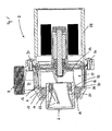
- a centrifugal pump 2 with a pump housing 4 is shown.
- the pump housing 4 has a suction opening 6 and an outlet opening 8.
- the suction opening 6 and the outlet opening 8 are fluidly connected to one another by a flow space 10, in which the impeller 12 is arranged.
- water flows through the suction opening 6 into the flow space 10, where it is accelerated by the rotating impeller 12 and pushed out of the centrifugal pump 2 via the outlet opening 8.
- an expansion body 14 which is separated in the embodiment of the impeller 12 by the volute casing 16.
- the spiral housing 16 has a wall 18, through which the expansion body 14 is held in its installed position. At the same time, the wall 18 limits the flow space 10 and the impeller 12.
- the spiral housing 16 has a projection 20 which is clamped on the inner surface of the pump housing 4 and thereby centers the volute 16 in its installation position.
- the projection 20 is configured in the embodiment as a circumferential ring.
- an intake manifold 22 is formed in the embodiment, which connects the suction port 6 with the flow space 10 as a flow channel. Inserted into the intake manifold 22 is an inflow funnel 24, whose flow cross-section decreases in the direction of flow. The inflow funnel 24 abuts against the inner surface of the pump housing 4 via contact surfaces 26.
- the volute 16 is designed as a one-piece molded body.
- the dimensions of the spiral housing 16 are selected so that the spiral housing 16 is positioned without play in the flow chamber 10 when the pump housing 4 is mounted on the motor housing 28.
- the volute casing is held by its dimensional adjustment to the internal dimensions of the pump housing 4 in its installed position.
- the position fixation of the spiral housing 16 results in the embodiment, in particular from the spiral housing 16 formed on top surfaces 30th
- a passage 32 surrounding the intake manifold 22 is formed in the exemplary embodiment, which circulates around the intake manifold 22.
- the passage gap 32 forms a flow opening through which water from the flow space 10 can penetrate into the installation space in which the expansion body 14 is located when water in the flow space 10 expands in volume by a phase change. Due to its flexible design, the expansion body 14 is compressed by the penetrating water and partially displaced. When the water that has turned to ice thaws again and the volume of the water located in the flow space 10 decreases again, the water located in the region of the expansion body 14 can again flow back into the flow space 10 through the passage gap 32. In this way, the centrifugal pump 2 is preserved from possible frost damage.
- Fig. 2 is a frontal view of the open pump housing 4 is shown.
- the spiral housing 16 is inserted.
- the wall 18 of the volute casing 16 forms an annular passage gap 32 in the abutting region on the intake manifold 22 by the corresponding dimensional design.
- the impeller-side end face of the inflow funnel 24 can be seen, through which the free flow cross-section of the intake manifold 22 is reduced.
- a pressure port 34 is formed, via which the water from the flow space 10 to the outlet port 8 is conveyed.
- Fig. 3 is an exploded view of the individual components used in the pump housing 4 to see.
- the expansion body 14 and the spiral housing 16 can be inserted into the pump housing 4.
- the suction opening 6 of the inflow funnel 24 is shown, which is insertable into the intake manifold 22.
- components for the spiral housing 16 and the inflow funnel 24 can be used in the pump housing 4, other shaped components that are adapted to a different shape of an impeller 12. Due to the possibility of being able to use differently shaped components in the pump housing 4 as spiral housing 16 and / or an inflow funnel 24, the pump housing 4 can be easily adapted to different wheels 12 and their particular performance characteristics.
Landscapes
- Engineering & Computer Science (AREA)
- Mechanical Engineering (AREA)
- General Engineering & Computer Science (AREA)
- Structures Of Non-Positive Displacement Pumps (AREA)
Priority Applications (3)
| Application Number | Priority Date | Filing Date | Title |
|---|---|---|---|
| EP11005738.7A EP2546525B1 (fr) | 2011-07-13 | 2011-07-13 | Pompe centrifuge dotée d'un boîtier à spirales |
| US13/543,842 US9222476B2 (en) | 2011-07-13 | 2012-07-08 | Rotary pump with spiral casing |
| CN201210467996.8A CN102954040B (zh) | 2011-07-13 | 2012-07-13 | 具有螺旋壳的叶轮泵 |
Applications Claiming Priority (1)
| Application Number | Priority Date | Filing Date | Title |
|---|---|---|---|
| EP11005738.7A EP2546525B1 (fr) | 2011-07-13 | 2011-07-13 | Pompe centrifuge dotée d'un boîtier à spirales |
Publications (2)
| Publication Number | Publication Date |
|---|---|
| EP2546525A1 true EP2546525A1 (fr) | 2013-01-16 |
| EP2546525B1 EP2546525B1 (fr) | 2017-03-29 |
Family
ID=44581929
Family Applications (1)
| Application Number | Title | Priority Date | Filing Date |
|---|---|---|---|
| EP11005738.7A Active EP2546525B1 (fr) | 2011-07-13 | 2011-07-13 | Pompe centrifuge dotée d'un boîtier à spirales |
Country Status (3)
| Country | Link |
|---|---|
| US (1) | US9222476B2 (fr) |
| EP (1) | EP2546525B1 (fr) |
| CN (1) | CN102954040B (fr) |
Cited By (2)
| Publication number | Priority date | Publication date | Assignee | Title |
|---|---|---|---|---|
| DE102018217179A1 (de) * | 2018-10-08 | 2020-04-09 | Continental Automotive Gmbh | Fluidpumpe, Wasserfördereinheit, Wassereinspritzsystem, Verbrennungsmotor und Fahrzeug |
| DE102018217176A1 (de) * | 2018-10-08 | 2020-04-09 | Continental Automotive Gmbh | Fluidpumpe, Wasserfördereinheit, Wassereinspritzsystem, Verbrennungsmotor und Fahrzeug |
Families Citing this family (3)
| Publication number | Priority date | Publication date | Assignee | Title |
|---|---|---|---|---|
| CN104235070A (zh) * | 2013-06-13 | 2014-12-24 | 德昌电机(深圳)有限公司 | 泵壳及具有该泵壳的泵 |
| US10890179B2 (en) * | 2015-12-24 | 2021-01-12 | Fluid-O-Tech Group S.R.L. | Container assembly for a pump |
| JP2021036134A (ja) * | 2019-08-30 | 2021-03-04 | 日本電産サンキョー株式会社 | ポンプ装置 |
Citations (3)
| Publication number | Priority date | Publication date | Assignee | Title |
|---|---|---|---|---|
| JPS5918297A (ja) * | 1982-07-20 | 1984-01-30 | Mitsubishi Electric Corp | うず巻ポンプ |
| JPH11294366A (ja) * | 1998-04-16 | 1999-10-26 | Nikkiso Co Ltd | 凍結防止機構付き極低温用ポンプ |
| WO2004020835A1 (fr) * | 2002-08-31 | 2004-03-11 | Oase Gmbh | Pompe a moteur submersible equipee d'un systeme antigel |
Family Cites Families (9)
| Publication number | Priority date | Publication date | Assignee | Title |
|---|---|---|---|---|
| US3776664A (en) * | 1972-08-18 | 1973-12-04 | A Kimmel | Small diameter irrigation pump |
| DE4005640A1 (de) * | 1990-02-22 | 1991-08-29 | Klein Schanzlin & Becker Ag | Spiralgehaeuse in blechbauweise |
| US6056506A (en) * | 1998-09-23 | 2000-05-02 | Emerson Electric Co. | Pump assembly for jetted tub |
| JP2002155883A (ja) * | 2000-11-22 | 2002-05-31 | Ebara Corp | マグネットポンプ及びモータ |
| KR100438083B1 (ko) * | 2002-02-23 | 2004-07-03 | 이상영 | 폐타이어를 이용한 펌프 |
| DE10331602B4 (de) * | 2002-08-31 | 2005-08-25 | Oase Gmbh | Tauchmotorpumpe mit Frostschutzeinrichtung |
| US8419358B2 (en) * | 2009-06-17 | 2013-04-16 | Sundyne, Llc | Flow output nozzle for centrifugal pump |
| CN101846102B (zh) * | 2010-06-03 | 2012-07-25 | 浙江利欧股份有限公司 | 防冻裂水泵 |
| CN102192157B (zh) * | 2011-05-16 | 2013-04-10 | 广州市白云泵业集团有限公司 | 一种立式内外混无轴封自吸泵 |
-
2011
- 2011-07-13 EP EP11005738.7A patent/EP2546525B1/fr active Active
-
2012
- 2012-07-08 US US13/543,842 patent/US9222476B2/en active Active
- 2012-07-13 CN CN201210467996.8A patent/CN102954040B/zh active Active
Patent Citations (3)
| Publication number | Priority date | Publication date | Assignee | Title |
|---|---|---|---|---|
| JPS5918297A (ja) * | 1982-07-20 | 1984-01-30 | Mitsubishi Electric Corp | うず巻ポンプ |
| JPH11294366A (ja) * | 1998-04-16 | 1999-10-26 | Nikkiso Co Ltd | 凍結防止機構付き極低温用ポンプ |
| WO2004020835A1 (fr) * | 2002-08-31 | 2004-03-11 | Oase Gmbh | Pompe a moteur submersible equipee d'un systeme antigel |
Cited By (5)
| Publication number | Priority date | Publication date | Assignee | Title |
|---|---|---|---|---|
| DE102018217179A1 (de) * | 2018-10-08 | 2020-04-09 | Continental Automotive Gmbh | Fluidpumpe, Wasserfördereinheit, Wassereinspritzsystem, Verbrennungsmotor und Fahrzeug |
| DE102018217176A1 (de) * | 2018-10-08 | 2020-04-09 | Continental Automotive Gmbh | Fluidpumpe, Wasserfördereinheit, Wassereinspritzsystem, Verbrennungsmotor und Fahrzeug |
| WO2020074286A1 (fr) * | 2018-10-08 | 2020-04-16 | Vitesco Technologies GmbH | Pompe à fluide, unité de refoulement d'eau, système d'injection d'eau, moteur à combustion interne et véhicule |
| DE102018217176B4 (de) | 2018-10-08 | 2020-06-10 | Continental Automotive Gmbh | Fluidpumpe, Wasserfördereinheit, Wassereinspritzsystem, Verbrennungsmotor und Fahrzeug |
| DE102018217179B4 (de) | 2018-10-08 | 2023-06-29 | Vitesco Technologies GmbH | Fluidpumpe, Wasserfördereinheit, Wassereinspritzsystem, Verbrennungsmotor und Fahrzeug |
Also Published As
| Publication number | Publication date |
|---|---|
| EP2546525B1 (fr) | 2017-03-29 |
| CN102954040B (zh) | 2017-03-01 |
| US9222476B2 (en) | 2015-12-29 |
| US20130017077A1 (en) | 2013-01-17 |
| CN102954040A (zh) | 2013-03-06 |
Similar Documents
| Publication | Publication Date | Title |
|---|---|---|
| DE112009000185B4 (de) | Blutpumpe und Pumpeinheit | |
| EP2546525B1 (fr) | Pompe centrifuge dotée d'un boîtier à spirales | |
| EP3008346B1 (fr) | Pompe | |
| EP3374642B1 (fr) | Pompe à liquide axiale électrique pour véhicule automobile | |
| EP2206924A2 (fr) | Pompe à palettes à débit variable dotée d'un anneau de commande pivotant | |
| WO2013092902A1 (fr) | Pompe centrifuge à rotor mouillé | |
| DE102011055599A1 (de) | Pumpe für einen Temperaturkreislauf in einem Fahrzeug | |
| DE102015100215B4 (de) | Seitenkanalgebläse für eine Verbrennungskraftmaschine | |
| EP1192359A1 (fr) | Pompe d'alimentation | |
| DE102006035408B4 (de) | Laufrad und Fluidpumpe, die das Laufrad aufweist | |
| EP2002123B1 (fr) | Pompe a fluide | |
| EP1945955B1 (fr) | Pompe a fluide | |
| EP2322803B1 (fr) | Pompe dotée d un embrayage magnétique | |
| DE10006983A1 (de) | Pumpenlaufrad für eine Kreiselpumpe, insbesondere für eine in Geschirrspülmaschinen oder Waschmaschinen einsetzbare Umwälzpumpe | |
| DE4221184A1 (de) | Aggregat zum Fördern von Kraftstoff aus einem Vorratstank zur Brennkraftmaschine eines Kraftfahrzeuges | |
| DE102011077777B3 (de) | Tauchpumpe und Verfahren zum Zusammenbau einer Tauchpumpe | |
| EP3299627B1 (fr) | Pompe d'alimentation | |
| EP3156663B1 (fr) | Groupe pompe centrifuge | |
| EP1148248A2 (fr) | Carter de pompe | |
| EP2786021B1 (fr) | Motopompe de compteur hydraulique | |
| DE4340011B4 (de) | Peripheralpumpe, insbesondere zum Fördern von Kraftstoff aus einem Vorratstank zur Brennkraftmaschine eines Kraftfahrzeuges | |
| DE102016209311A1 (de) | Elektrische kreiselpumpe | |
| EP2205850A1 (fr) | Pompe à carburant destinée à transporter du carburant d'un réservoir vers un moteur à combustion interne | |
| DE10019820C2 (de) | Pumpe, insbesondere Umwälzpumpe für Haushaltsmaschinen wie Geschirrspülmaschinen | |
| EP3864294B1 (fr) | Pompe à fluide, unité de refoulement d'eau, système d'injection d'eau, moteur à combustion interne et véhicule |
Legal Events
| Date | Code | Title | Description |
|---|---|---|---|
| PUAI | Public reference made under article 153(3) epc to a published international application that has entered the european phase |
Free format text: ORIGINAL CODE: 0009012 |
|
| 17P | Request for examination filed |
Effective date: 20120430 |
|
| AK | Designated contracting states |
Kind code of ref document: A1 Designated state(s): AL AT BE BG CH CY CZ DE DK EE ES FI FR GB GR HR HU IE IS IT LI LT LU LV MC MK MT NL NO PL PT RO RS SE SI SK SM TR |
|
| AX | Request for extension of the european patent |
Extension state: BA ME |
|
| GRAP | Despatch of communication of intention to grant a patent |
Free format text: ORIGINAL CODE: EPIDOSNIGR1 |
|
| INTG | Intention to grant announced |
Effective date: 20161102 |
|
| GRAS | Grant fee paid |
Free format text: ORIGINAL CODE: EPIDOSNIGR3 |
|
| GRAA | (expected) grant |
Free format text: ORIGINAL CODE: 0009210 |
|
| AK | Designated contracting states |
Kind code of ref document: B1 Designated state(s): AL AT BE BG CH CY CZ DE DK EE ES FI FR GB GR HR HU IE IS IT LI LT LU LV MC MK MT NL NO PL PT RO RS SE SI SK SM TR |
|
| REG | Reference to a national code |
Ref country code: GB Ref legal event code: FG4D Free format text: NOT ENGLISH |
|
| REG | Reference to a national code |
Ref country code: CH Ref legal event code: EP |
|
| REG | Reference to a national code |
Ref country code: AT Ref legal event code: REF Ref document number: 880054 Country of ref document: AT Kind code of ref document: T Effective date: 20170415 |
|
| REG | Reference to a national code |
Ref country code: IE Ref legal event code: FG4D Free format text: LANGUAGE OF EP DOCUMENT: GERMAN |
|
| REG | Reference to a national code |
Ref country code: DE Ref legal event code: R096 Ref document number: 502011011919 Country of ref document: DE |
|
| REG | Reference to a national code |
Ref country code: NL Ref legal event code: FP |
|
| REG | Reference to a national code |
Ref country code: FR Ref legal event code: PLFP Year of fee payment: 7 |
|
| PG25 | Lapsed in a contracting state [announced via postgrant information from national office to epo] |
Ref country code: HR Free format text: LAPSE BECAUSE OF FAILURE TO SUBMIT A TRANSLATION OF THE DESCRIPTION OR TO PAY THE FEE WITHIN THE PRESCRIBED TIME-LIMIT Effective date: 20170329 Ref country code: FI Free format text: LAPSE BECAUSE OF FAILURE TO SUBMIT A TRANSLATION OF THE DESCRIPTION OR TO PAY THE FEE WITHIN THE PRESCRIBED TIME-LIMIT Effective date: 20170329 Ref country code: NO Free format text: LAPSE BECAUSE OF FAILURE TO SUBMIT A TRANSLATION OF THE DESCRIPTION OR TO PAY THE FEE WITHIN THE PRESCRIBED TIME-LIMIT Effective date: 20170629 Ref country code: GR Free format text: LAPSE BECAUSE OF FAILURE TO SUBMIT A TRANSLATION OF THE DESCRIPTION OR TO PAY THE FEE WITHIN THE PRESCRIBED TIME-LIMIT Effective date: 20170630 Ref country code: LT Free format text: LAPSE BECAUSE OF FAILURE TO SUBMIT A TRANSLATION OF THE DESCRIPTION OR TO PAY THE FEE WITHIN THE PRESCRIBED TIME-LIMIT Effective date: 20170329 |
|
| PG25 | Lapsed in a contracting state [announced via postgrant information from national office to epo] |
Ref country code: LV Free format text: LAPSE BECAUSE OF FAILURE TO SUBMIT A TRANSLATION OF THE DESCRIPTION OR TO PAY THE FEE WITHIN THE PRESCRIBED TIME-LIMIT Effective date: 20170329 Ref country code: BG Free format text: LAPSE BECAUSE OF FAILURE TO SUBMIT A TRANSLATION OF THE DESCRIPTION OR TO PAY THE FEE WITHIN THE PRESCRIBED TIME-LIMIT Effective date: 20170629 Ref country code: RS Free format text: LAPSE BECAUSE OF FAILURE TO SUBMIT A TRANSLATION OF THE DESCRIPTION OR TO PAY THE FEE WITHIN THE PRESCRIBED TIME-LIMIT Effective date: 20170329 Ref country code: SE Free format text: LAPSE BECAUSE OF FAILURE TO SUBMIT A TRANSLATION OF THE DESCRIPTION OR TO PAY THE FEE WITHIN THE PRESCRIBED TIME-LIMIT Effective date: 20170329 |
|
| PG25 | Lapsed in a contracting state [announced via postgrant information from national office to epo] |
Ref country code: EE Free format text: LAPSE BECAUSE OF FAILURE TO SUBMIT A TRANSLATION OF THE DESCRIPTION OR TO PAY THE FEE WITHIN THE PRESCRIBED TIME-LIMIT Effective date: 20170329 Ref country code: RO Free format text: LAPSE BECAUSE OF FAILURE TO SUBMIT A TRANSLATION OF THE DESCRIPTION OR TO PAY THE FEE WITHIN THE PRESCRIBED TIME-LIMIT Effective date: 20170329 Ref country code: CZ Free format text: LAPSE BECAUSE OF FAILURE TO SUBMIT A TRANSLATION OF THE DESCRIPTION OR TO PAY THE FEE WITHIN THE PRESCRIBED TIME-LIMIT Effective date: 20170329 Ref country code: ES Free format text: LAPSE BECAUSE OF FAILURE TO SUBMIT A TRANSLATION OF THE DESCRIPTION OR TO PAY THE FEE WITHIN THE PRESCRIBED TIME-LIMIT Effective date: 20170329 Ref country code: SK Free format text: LAPSE BECAUSE OF FAILURE TO SUBMIT A TRANSLATION OF THE DESCRIPTION OR TO PAY THE FEE WITHIN THE PRESCRIBED TIME-LIMIT Effective date: 20170329 Ref country code: IT Free format text: LAPSE BECAUSE OF FAILURE TO SUBMIT A TRANSLATION OF THE DESCRIPTION OR TO PAY THE FEE WITHIN THE PRESCRIBED TIME-LIMIT Effective date: 20170329 |
|
| PG25 | Lapsed in a contracting state [announced via postgrant information from national office to epo] |
Ref country code: IS Free format text: LAPSE BECAUSE OF FAILURE TO SUBMIT A TRANSLATION OF THE DESCRIPTION OR TO PAY THE FEE WITHIN THE PRESCRIBED TIME-LIMIT Effective date: 20170729 Ref country code: SM Free format text: LAPSE BECAUSE OF FAILURE TO SUBMIT A TRANSLATION OF THE DESCRIPTION OR TO PAY THE FEE WITHIN THE PRESCRIBED TIME-LIMIT Effective date: 20170329 Ref country code: PT Free format text: LAPSE BECAUSE OF FAILURE TO SUBMIT A TRANSLATION OF THE DESCRIPTION OR TO PAY THE FEE WITHIN THE PRESCRIBED TIME-LIMIT Effective date: 20170731 Ref country code: PL Free format text: LAPSE BECAUSE OF FAILURE TO SUBMIT A TRANSLATION OF THE DESCRIPTION OR TO PAY THE FEE WITHIN THE PRESCRIBED TIME-LIMIT Effective date: 20170329 |
|
| REG | Reference to a national code |
Ref country code: DE Ref legal event code: R097 Ref document number: 502011011919 Country of ref document: DE |
|
| PG25 | Lapsed in a contracting state [announced via postgrant information from national office to epo] |
Ref country code: DK Free format text: LAPSE BECAUSE OF FAILURE TO SUBMIT A TRANSLATION OF THE DESCRIPTION OR TO PAY THE FEE WITHIN THE PRESCRIBED TIME-LIMIT Effective date: 20170329 |
|
| PLBE | No opposition filed within time limit |
Free format text: ORIGINAL CODE: 0009261 |
|
| STAA | Information on the status of an ep patent application or granted ep patent |
Free format text: STATUS: NO OPPOSITION FILED WITHIN TIME LIMIT |
|
| REG | Reference to a national code |
Ref country code: CH Ref legal event code: PL |
|
| 26N | No opposition filed |
Effective date: 20180103 |
|
| REG | Reference to a national code |
Ref country code: IE Ref legal event code: MM4A |
|
| PG25 | Lapsed in a contracting state [announced via postgrant information from national office to epo] |
Ref country code: IE Free format text: LAPSE BECAUSE OF NON-PAYMENT OF DUE FEES Effective date: 20170713 Ref country code: CH Free format text: LAPSE BECAUSE OF NON-PAYMENT OF DUE FEES Effective date: 20170731 Ref country code: LI Free format text: LAPSE BECAUSE OF NON-PAYMENT OF DUE FEES Effective date: 20170731 |
|
| PG25 | Lapsed in a contracting state [announced via postgrant information from national office to epo] |
Ref country code: SI Free format text: LAPSE BECAUSE OF FAILURE TO SUBMIT A TRANSLATION OF THE DESCRIPTION OR TO PAY THE FEE WITHIN THE PRESCRIBED TIME-LIMIT Effective date: 20170329 |
|
| PG25 | Lapsed in a contracting state [announced via postgrant information from national office to epo] |
Ref country code: LU Free format text: LAPSE BECAUSE OF NON-PAYMENT OF DUE FEES Effective date: 20170713 |
|
| REG | Reference to a national code |
Ref country code: FR Ref legal event code: PLFP Year of fee payment: 8 |
|
| REG | Reference to a national code |
Ref country code: AT Ref legal event code: MM01 Ref document number: 880054 Country of ref document: AT Kind code of ref document: T Effective date: 20170713 |
|
| PG25 | Lapsed in a contracting state [announced via postgrant information from national office to epo] |
Ref country code: MT Free format text: LAPSE BECAUSE OF FAILURE TO SUBMIT A TRANSLATION OF THE DESCRIPTION OR TO PAY THE FEE WITHIN THE PRESCRIBED TIME-LIMIT Effective date: 20170329 |
|
| PG25 | Lapsed in a contracting state [announced via postgrant information from national office to epo] |
Ref country code: AT Free format text: LAPSE BECAUSE OF NON-PAYMENT OF DUE FEES Effective date: 20170713 |
|
| PG25 | Lapsed in a contracting state [announced via postgrant information from national office to epo] |
Ref country code: MC Free format text: LAPSE BECAUSE OF FAILURE TO SUBMIT A TRANSLATION OF THE DESCRIPTION OR TO PAY THE FEE WITHIN THE PRESCRIBED TIME-LIMIT Effective date: 20170329 Ref country code: HU Free format text: LAPSE BECAUSE OF FAILURE TO SUBMIT A TRANSLATION OF THE DESCRIPTION OR TO PAY THE FEE WITHIN THE PRESCRIBED TIME-LIMIT; INVALID AB INITIO Effective date: 20110713 |
|
| PG25 | Lapsed in a contracting state [announced via postgrant information from national office to epo] |
Ref country code: CY Free format text: LAPSE BECAUSE OF NON-PAYMENT OF DUE FEES Effective date: 20170329 |
|
| PG25 | Lapsed in a contracting state [announced via postgrant information from national office to epo] |
Ref country code: MK Free format text: LAPSE BECAUSE OF FAILURE TO SUBMIT A TRANSLATION OF THE DESCRIPTION OR TO PAY THE FEE WITHIN THE PRESCRIBED TIME-LIMIT Effective date: 20170329 |
|
| PG25 | Lapsed in a contracting state [announced via postgrant information from national office to epo] |
Ref country code: TR Free format text: LAPSE BECAUSE OF FAILURE TO SUBMIT A TRANSLATION OF THE DESCRIPTION OR TO PAY THE FEE WITHIN THE PRESCRIBED TIME-LIMIT Effective date: 20170329 |
|
| PG25 | Lapsed in a contracting state [announced via postgrant information from national office to epo] |
Ref country code: AL Free format text: LAPSE BECAUSE OF FAILURE TO SUBMIT A TRANSLATION OF THE DESCRIPTION OR TO PAY THE FEE WITHIN THE PRESCRIBED TIME-LIMIT Effective date: 20170329 |
|
| PGFP | Annual fee paid to national office [announced via postgrant information from national office to epo] |
Ref country code: NL Payment date: 20230720 Year of fee payment: 13 |
|
| PGFP | Annual fee paid to national office [announced via postgrant information from national office to epo] |
Ref country code: GB Payment date: 20230724 Year of fee payment: 13 |
|
| PGFP | Annual fee paid to national office [announced via postgrant information from national office to epo] |
Ref country code: FR Payment date: 20230724 Year of fee payment: 13 Ref country code: DE Payment date: 20230720 Year of fee payment: 13 Ref country code: BE Payment date: 20230719 Year of fee payment: 13 |