EP2546292B1 - Mousse de résine et matériau d'étanchéité en mousse - Google Patents
Mousse de résine et matériau d'étanchéité en mousse Download PDFInfo
- Publication number
- EP2546292B1 EP2546292B1 EP12175904.7A EP12175904A EP2546292B1 EP 2546292 B1 EP2546292 B1 EP 2546292B1 EP 12175904 A EP12175904 A EP 12175904A EP 2546292 B1 EP2546292 B1 EP 2546292B1
- Authority
- EP
- European Patent Office
- Prior art keywords
- foam
- resin
- resin foam
- pressure
- sealing material
- Prior art date
- Legal status (The legal status is an assumption and is not a legal conclusion. Google has not performed a legal analysis and makes no representation as to the accuracy of the status listed.)
- Active
Links
Images

Classifications
-
- C—CHEMISTRY; METALLURGY
- C08—ORGANIC MACROMOLECULAR COMPOUNDS; THEIR PREPARATION OR CHEMICAL WORKING-UP; COMPOSITIONS BASED THEREON
- C08J—WORKING-UP; GENERAL PROCESSES OF COMPOUNDING; AFTER-TREATMENT NOT COVERED BY SUBCLASSES C08B, C08C, C08F, C08G or C08H
- C08J9/00—Working-up of macromolecular substances to porous or cellular articles or materials; After-treatment thereof
- C08J9/0004—Use of compounding ingredients, the chemical constitution of which is unknown, broadly defined, or irrelevant
-
- C—CHEMISTRY; METALLURGY
- C08—ORGANIC MACROMOLECULAR COMPOUNDS; THEIR PREPARATION OR CHEMICAL WORKING-UP; COMPOSITIONS BASED THEREON
- C08J—WORKING-UP; GENERAL PROCESSES OF COMPOUNDING; AFTER-TREATMENT NOT COVERED BY SUBCLASSES C08B, C08C, C08F, C08G or C08H
- C08J9/00—Working-up of macromolecular substances to porous or cellular articles or materials; After-treatment thereof
- C08J9/0061—Working-up of macromolecular substances to porous or cellular articles or materials; After-treatment thereof characterized by the use of several polymeric components
-
- C—CHEMISTRY; METALLURGY
- C08—ORGANIC MACROMOLECULAR COMPOUNDS; THEIR PREPARATION OR CHEMICAL WORKING-UP; COMPOSITIONS BASED THEREON
- C08J—WORKING-UP; GENERAL PROCESSES OF COMPOUNDING; AFTER-TREATMENT NOT COVERED BY SUBCLASSES C08B, C08C, C08F, C08G or C08H
- C08J9/00—Working-up of macromolecular substances to porous or cellular articles or materials; After-treatment thereof
- C08J9/04—Working-up of macromolecular substances to porous or cellular articles or materials; After-treatment thereof using blowing gases generated by a previously added blowing agent
- C08J9/06—Working-up of macromolecular substances to porous or cellular articles or materials; After-treatment thereof using blowing gases generated by a previously added blowing agent by a chemical blowing agent
- C08J9/08—Working-up of macromolecular substances to porous or cellular articles or materials; After-treatment thereof using blowing gases generated by a previously added blowing agent by a chemical blowing agent developing carbon dioxide
-
- C—CHEMISTRY; METALLURGY
- C08—ORGANIC MACROMOLECULAR COMPOUNDS; THEIR PREPARATION OR CHEMICAL WORKING-UP; COMPOSITIONS BASED THEREON
- C08J—WORKING-UP; GENERAL PROCESSES OF COMPOUNDING; AFTER-TREATMENT NOT COVERED BY SUBCLASSES C08B, C08C, C08F, C08G or C08H
- C08J9/00—Working-up of macromolecular substances to porous or cellular articles or materials; After-treatment thereof
- C08J9/04—Working-up of macromolecular substances to porous or cellular articles or materials; After-treatment thereof using blowing gases generated by a previously added blowing agent
- C08J9/12—Working-up of macromolecular substances to porous or cellular articles or materials; After-treatment thereof using blowing gases generated by a previously added blowing agent by a physical blowing agent
- C08J9/122—Hydrogen, oxygen, CO2, nitrogen or noble gases
-
- C—CHEMISTRY; METALLURGY
- C09—DYES; PAINTS; POLISHES; NATURAL RESINS; ADHESIVES; COMPOSITIONS NOT OTHERWISE PROVIDED FOR; APPLICATIONS OF MATERIALS NOT OTHERWISE PROVIDED FOR
- C09J—ADHESIVES; NON-MECHANICAL ASPECTS OF ADHESIVE PROCESSES IN GENERAL; ADHESIVE PROCESSES NOT PROVIDED FOR ELSEWHERE; USE OF MATERIALS AS ADHESIVES
- C09J7/00—Adhesives in the form of films or foils
- C09J7/20—Adhesives in the form of films or foils characterised by their carriers
- C09J7/22—Plastics; Metallised plastics
- C09J7/26—Porous or cellular plastics
-
- C—CHEMISTRY; METALLURGY
- C09—DYES; PAINTS; POLISHES; NATURAL RESINS; ADHESIVES; COMPOSITIONS NOT OTHERWISE PROVIDED FOR; APPLICATIONS OF MATERIALS NOT OTHERWISE PROVIDED FOR
- C09J—ADHESIVES; NON-MECHANICAL ASPECTS OF ADHESIVE PROCESSES IN GENERAL; ADHESIVE PROCESSES NOT PROVIDED FOR ELSEWHERE; USE OF MATERIALS AS ADHESIVES
- C09J7/00—Adhesives in the form of films or foils
- C09J7/30—Adhesives in the form of films or foils characterised by the adhesive composition
- C09J7/38—Pressure-sensitive adhesives [PSA]
- C09J7/381—Pressure-sensitive adhesives [PSA] based on macromolecular compounds obtained by reactions involving only carbon-to-carbon unsaturated bonds
- C09J7/385—Acrylic polymers
-
- C—CHEMISTRY; METALLURGY
- C09—DYES; PAINTS; POLISHES; NATURAL RESINS; ADHESIVES; COMPOSITIONS NOT OTHERWISE PROVIDED FOR; APPLICATIONS OF MATERIALS NOT OTHERWISE PROVIDED FOR
- C09K—MATERIALS FOR MISCELLANEOUS APPLICATIONS, NOT PROVIDED FOR ELSEWHERE
- C09K3/00—Materials not provided for elsewhere
- C09K3/10—Materials in mouldable or extrudable form for sealing or packing joints or covers
-
- C—CHEMISTRY; METALLURGY
- C08—ORGANIC MACROMOLECULAR COMPOUNDS; THEIR PREPARATION OR CHEMICAL WORKING-UP; COMPOSITIONS BASED THEREON
- C08J—WORKING-UP; GENERAL PROCESSES OF COMPOUNDING; AFTER-TREATMENT NOT COVERED BY SUBCLASSES C08B, C08C, C08F, C08G or C08H
- C08J2201/00—Foams characterised by the foaming process
- C08J2201/02—Foams characterised by the foaming process characterised by mechanical pre- or post-treatments
- C08J2201/032—Impregnation of a formed object with a gas
-
- C—CHEMISTRY; METALLURGY
- C08—ORGANIC MACROMOLECULAR COMPOUNDS; THEIR PREPARATION OR CHEMICAL WORKING-UP; COMPOSITIONS BASED THEREON
- C08J—WORKING-UP; GENERAL PROCESSES OF COMPOUNDING; AFTER-TREATMENT NOT COVERED BY SUBCLASSES C08B, C08C, C08F, C08G or C08H
- C08J2203/00—Foams characterized by the expanding agent
- C08J2203/06—CO2, N2 or noble gases
-
- C—CHEMISTRY; METALLURGY
- C08—ORGANIC MACROMOLECULAR COMPOUNDS; THEIR PREPARATION OR CHEMICAL WORKING-UP; COMPOSITIONS BASED THEREON
- C08J—WORKING-UP; GENERAL PROCESSES OF COMPOUNDING; AFTER-TREATMENT NOT COVERED BY SUBCLASSES C08B, C08C, C08F, C08G or C08H
- C08J2203/00—Foams characterized by the expanding agent
- C08J2203/08—Supercritical fluid
-
- C—CHEMISTRY; METALLURGY
- C08—ORGANIC MACROMOLECULAR COMPOUNDS; THEIR PREPARATION OR CHEMICAL WORKING-UP; COMPOSITIONS BASED THEREON
- C08J—WORKING-UP; GENERAL PROCESSES OF COMPOUNDING; AFTER-TREATMENT NOT COVERED BY SUBCLASSES C08B, C08C, C08F, C08G or C08H
- C08J2205/00—Foams characterised by their properties
- C08J2205/04—Foams characterised by their properties characterised by the foam pores
- C08J2205/044—Micropores, i.e. average diameter being between 0,1 micrometer and 0,1 millimeter
-
- C—CHEMISTRY; METALLURGY
- C08—ORGANIC MACROMOLECULAR COMPOUNDS; THEIR PREPARATION OR CHEMICAL WORKING-UP; COMPOSITIONS BASED THEREON
- C08J—WORKING-UP; GENERAL PROCESSES OF COMPOUNDING; AFTER-TREATMENT NOT COVERED BY SUBCLASSES C08B, C08C, C08F, C08G or C08H
- C08J2207/00—Foams characterised by their intended use
- C08J2207/02—Adhesive
-
- C—CHEMISTRY; METALLURGY
- C08—ORGANIC MACROMOLECULAR COMPOUNDS; THEIR PREPARATION OR CHEMICAL WORKING-UP; COMPOSITIONS BASED THEREON
- C08J—WORKING-UP; GENERAL PROCESSES OF COMPOUNDING; AFTER-TREATMENT NOT COVERED BY SUBCLASSES C08B, C08C, C08F, C08G or C08H
- C08J2323/00—Characterised by the use of homopolymers or copolymers of unsaturated aliphatic hydrocarbons having only one carbon-to-carbon double bond; Derivatives of such polymers
- C08J2323/26—Characterised by the use of homopolymers or copolymers of unsaturated aliphatic hydrocarbons having only one carbon-to-carbon double bond; Derivatives of such polymers modified by chemical after-treatment
-
- C—CHEMISTRY; METALLURGY
- C08—ORGANIC MACROMOLECULAR COMPOUNDS; THEIR PREPARATION OR CHEMICAL WORKING-UP; COMPOSITIONS BASED THEREON
- C08J—WORKING-UP; GENERAL PROCESSES OF COMPOUNDING; AFTER-TREATMENT NOT COVERED BY SUBCLASSES C08B, C08C, C08F, C08G or C08H
- C08J2423/00—Characterised by the use of homopolymers or copolymers of unsaturated aliphatic hydrocarbons having only one carbon-to-carbon double bond; Derivatives of such polymers
- C08J2423/02—Characterised by the use of homopolymers or copolymers of unsaturated aliphatic hydrocarbons having only one carbon-to-carbon double bond; Derivatives of such polymers not modified by chemical after treatment
- C08J2423/10—Homopolymers or copolymers of propene
- C08J2423/12—Polypropene
-
- C—CHEMISTRY; METALLURGY
- C09—DYES; PAINTS; POLISHES; NATURAL RESINS; ADHESIVES; COMPOSITIONS NOT OTHERWISE PROVIDED FOR; APPLICATIONS OF MATERIALS NOT OTHERWISE PROVIDED FOR
- C09J—ADHESIVES; NON-MECHANICAL ASPECTS OF ADHESIVE PROCESSES IN GENERAL; ADHESIVE PROCESSES NOT PROVIDED FOR ELSEWHERE; USE OF MATERIALS AS ADHESIVES
- C09J2423/00—Presence of polyolefin
- C09J2423/006—Presence of polyolefin in the substrate
-
- C—CHEMISTRY; METALLURGY
- C09—DYES; PAINTS; POLISHES; NATURAL RESINS; ADHESIVES; COMPOSITIONS NOT OTHERWISE PROVIDED FOR; APPLICATIONS OF MATERIALS NOT OTHERWISE PROVIDED FOR
- C09J—ADHESIVES; NON-MECHANICAL ASPECTS OF ADHESIVE PROCESSES IN GENERAL; ADHESIVE PROCESSES NOT PROVIDED FOR ELSEWHERE; USE OF MATERIALS AS ADHESIVES
- C09J2433/00—Presence of (meth)acrylic polymer
-
- Y—GENERAL TAGGING OF NEW TECHNOLOGICAL DEVELOPMENTS; GENERAL TAGGING OF CROSS-SECTIONAL TECHNOLOGIES SPANNING OVER SEVERAL SECTIONS OF THE IPC; TECHNICAL SUBJECTS COVERED BY FORMER USPC CROSS-REFERENCE ART COLLECTIONS [XRACs] AND DIGESTS
- Y10—TECHNICAL SUBJECTS COVERED BY FORMER USPC
- Y10T—TECHNICAL SUBJECTS COVERED BY FORMER US CLASSIFICATION
- Y10T428/00—Stock material or miscellaneous articles
- Y10T428/249921—Web or sheet containing structurally defined element or component
- Y10T428/249953—Composite having voids in a component [e.g., porous, cellular, etc.]
- Y10T428/249982—With component specified as adhesive or bonding agent
- Y10T428/249983—As outermost component
Definitions
- the present invention relates to a resin foam and a foam sealing material comprising the resin foam. More specifically, the present invention relates to a resin foam having excellent flexibility and dustproofness, a low spreadability, a small elongation at break, and good assemblability, and to a sealing material comprising the resin foam.
- Foams have been used for fixing optical members such as image display members (such as image display members which are fixed to image display devices such as liquid crystal displays, electroluminescence displays, and plasma displays) and cameras and lenses (such as cameras and lenses which are fixed to so-called "cellular phones” and “personal digital assistants" to a predetermined site (such as a fixing part). Flexibility is required in a foam used in this site, and examples of such a foam include a urethane foam. Among the urethane foam, one having a relatively high expansion ratio is preferred, and specifically, a polyurethane foam having a density of 0.1 to 0.15 g/cm 3 is known (refer to Patent Literature 1).
- the above polyurethane foam still has insufficient flexibility and may have a problem in terms of step followability or cushioning characteristics.
- a foam excellent in step followability there is known a foam (resin foam) which has not only excellent dustproofness but also excellent flexibility that can follow even a fine clearance (refer to Patent Literature 2).
- the above foam has such a problem that since it has excellent flexibility but has a low tensile modulus of elasticity, it is stretched when it is pulled, that is, it is plastically deformed when it is pulled, and a predetermined size cannot be obtained.
- a housing such as a housing of a large-sized liquid crystal television
- a conventional foam sealing material for example, a foam sealing material comprising the above resin foam of Patent Literature 2 which satisfies flexibility required as a sealing material has such a problem that when it is pulled, it is stretched to a length exceeding a desired size, thus preventing it from being assembled.
- Patent Literature 3 and 4 For further examples of conventional foam sealing materials, reference is made to Patent Literature 3 and 4.
- an object of the present invention is to provide a resin foam excellent in dustproofness and assemblability.
- the present invention provides a resin foam having a repulsive stress at 80% compression of 1.0 to 9.0 N/cm 2 and a tensile modulus of elasticity of 5.0 to 14.0 MPa, wherein the repulsive stress at 80% compression is defined as a repulsive stress when a resin foam is compressed by 80% of the initial thickness, the tensile modulus of elasticity and the repulsive stress at 80% compression being determined in accordance with JIS K6767, wherein the resin foam has an average cell diameter of 15 to 100 ⁇ m and an apparent density of 0.01 to 0.10 g/cm 3 , the average cell diameter being determined by capturing an enlarged image of a cellular portion of a resin-foam cross section using a microscope, measuring the area of all the cells appeared in a definite area (1 mm 2 ) of the cut surface, converting the area to the equivalent circle diameter, and then averaging it with the number of cells; and wherein the resin foam comprises a polypropylene and
- the resin foam is preferably formed through the steps of impregnating a resin composition with an inert gas and subjecting the impregnated resin composition to decompression.
- the inert gas is preferably carbon dioxide. Further, the inert gas is preferably in a supercritical state.
- the present invention provides a foam sealing material comprising the resin foam.
- the foam sealing material preferably has an adhesive layer formed on the resin foam.
- the adhesive layer is preferably formed through a film layer. Further, the adhesive layer is preferably an acrylic pressure-sensitive adhesive layer.
- the resin foam of the present invention has a repulsive stress at 80% compression and a tensile modulus of elasticity within a predetermined range, it is excellent in dustproofness and assemblability (ease of arranging or fixing to a predetermined place).
- the resin foam of the present invention is a foam comprising a resin, and is obtained by subjecting a resin composition to foam molding.
- the resin composition is a composition used for forming the resin foam of the present invention, and contains at least a polypropylene and an olefinic thermoplastic vulcanizate (TPV).
- TPV thermoplastic vulcanizate
- the shape of the resin foam of the present invention is preferably a sheet form (including a film form) and a tape form, but is not particularly limited thereto.
- the resin foam of the present invention preferably has a closed cell structure or semi-open/semi-closed cell structure as a cell structure in terms of the coexistence of dustproofness and flexibility, but is not particularly limited thereto.
- the semi-open/semi-closed cell structure is a cell structure containing both a closed cell moiety and an open cell moiety, and the ratio between these moieties is not particularly limited.
- the resin foam of the present invention preferably has a semi-open/semi-closed cell structure as a cell structure, and the resin foam preferably has a cell structure in which a closed cell moiety occupies 40% or less, more preferably 30% or less.
- the average cell diameter of the cell structure of the resin foam of the present invention is 15 to 100 ⁇ m, preferably 20 to 80 ⁇ m.
- the upper limit of the average cell diameter is set to 100 ⁇ m or less, dustproofness can be increased, and light blocking effect can be improved.
- the lower limit of the average cell diameter is set to 15 ⁇ m or more, flexibility and cushioning properties (impact absorbing properties) can be improved.
- the cell structure and the average cell diameter of the resin foam can be determined, for example, by cutting the resin foam, capturing an image of the cell structure of the cross section with a digital microscope, and analyzing the image.
- the apparent density of the resin foam of the present invention is 0.01 to 0.10 g/cm 3 , preferably 0.02 to 0.08 g/cm 3 . If the apparent density is less than 0.01 g/cm 3 , a problem in strength may occur, thereby preventing good processability (particularly punchability) from being obtained. On the other hand, if the apparent density exceeds 0.10 g/cm 3 , flexibility may be reduced to reduce followability to fine clearance.
- the repulsive stress at 80% compression of the resin foam of the present invention is 1.0 to 9.0 N/cm 2 , preferably 1.5 to 8.0 N/cm 2 , more preferably 2.0 to 7.0 N/cm 2 in terms of dustproofness and flexibility. Note that the repulsive stress at 80% compression is a repulsive stress when a resin foam is compressed by 80% of the initial thickness.
- the repulsive stress at 50% compression of the resin foam of the present invention is preferably 0.1 to 4.0 N/cm 2 , more preferably 0.5 to 3.0 N/cm 2 , in terms of dustproofness and flexibility, but is not particularly limited thereto.
- the repulsive stress at 50% compression is a repulsive stress when a resin foam is compressed by 50% of the initial thickness.
- the resin foam of the present invention has such a repulsive stress at compression, particularly the repulsive stress at 80% compression as described above, it is excellent in dustproofness and flexibility. It is also excellent in followability to fine clearance, particularly followability to fine clearance having fine steps.
- the fine clearance include a clearance having a size of 0.05 to 2.5 mm. Further, the size of the fine step in the above fine clearance having fine steps is, for example, 10 to 500 ⁇ m.
- the tensile modulus of elasticity of the resin foam of the present invention is 5.0 to 14.0 MPa, preferably 5.5 to 13.5 MPa, more preferably 6.0 to 13.0 MPa. Since the resin foam of the present invention has such a tensile modulus of elasticity, it has low spreadability and is excellent in assemblability. Note that if the tensile modulus of elasticity is less than 5.0 MPa, the resin foam may be plastically deformed to an extent that a desired size is exceeded when it is pulled, which may lead to a problem that the resin foam cannot be applied to the clearance.
- the tensile modulus of elasticity is determined by the tensile test according to JIS K 6767.
- the breaking strength (tensile strength) of the resin foam of the present invention is preferably 0.60 to 1.10 MPa, more preferably 0.70 to 1.05 MPa, in terms of assemblability, particularly workability in assembling operation, but is not particularly limited thereto. Note that the breaking strength is determined based on JIS K 6767.
- the elongation at break (elongation) of the resin foam of the present invention is preferably 50 to 200%, more preferably 80 to 150%, in terms of assemblability, particularly workability in assembling operation, but is not particularly limited thereto. Note that the elongation at break is determined based on JIS K 6767.
- the resin foam of the present invention comprises a polypropylene resin.
- the thermoplastic resin also includes an olefinic elastomer. This is because an olefinic elastomer has good compatibility with a polypropylene resin.
- the olefinic elastomer is of a type in which the resin component A and the rubber component B are dynamically heat-treated in the presence of a crosslinking agent (thermoplastic vulcanizate, TPV).
- TPV thermoplastic vulcanizate
- an olefinic thermoplastic vulcanizate is used as the olefinic elastomer, in terms of improving dustproofness, flexibility, and step followability by reducing the repulsive stress at compression (repulsive stress at 50% compression and repulsive stress at 80% compression) and in terms of improving assemblability by reducing elongation at break by controlling tensile modulus of elasticity.
- the resin foam of the present invention comprises an olefinic thermoplastic vulcanizate (TPV).
- TPV olefinic thermoplastic vulcanizate
- TPO uncrosslinked thermoplastic olefinic elastomer
- the resin foam of the present invention comprises an olefinic thermoplastic vulcanizate (TPV)
- the recovery properties after the foam is released from a compression state will be improved, thereby capable of further improving dustproofness; and the elasticity will also be improved, thereby capable of further improving assemblability.
- the resin foam of the present invention comprises an olefinic thermoplastic vulcanizate (TPV)
- an end will not collapse at punching, thereby capable of improving processability.
- the olefinic thermoplastic vulcanizate is obtained by dynamically heat-treating a mixture containing a resin component A (olefinic resin component A) forming a matrix and a rubber component B forming a domain in the presence of a crosslinking agent, and is a multiphase polymer having a sea island structure in which crosslinked rubber particles are finely dispersed as a domain (island phase) in the resin component A which is a matrix (sea phase).
- thermoplastic vulcanizate when incorporated into the resin foam of the present invention, a composition comprising the olefinic thermoplastic vulcanizate and additives (such as a colorant such as carbon black and a softener) may be used.
- additives such as a colorant such as carbon black and a softener
- the resin foam of the present invention preferably comprises a material excellent in so-called rubber elasticity in terms of achieving good dustproofness and good assemblability.
- the resin foam of the present invention comprises a polypropylene resin and the olefinic thermoplastic vulcanizate (TPV).
- the proportion of these components is not particularly limited. However, if the proportion of the olefinic thermoplastic vulcanizate (TPV)is too low, the resulting resin foam may have a reduced flexibility or the resin foam may be easily stretched to reduce assemblability. On the other hand, if the proportion of the olefinic thermoplastic vulcanizate (TPV)is too high, outgassing may easily occur during the formation of the foam, thereby preventing a highly expanded foam from being obtained.
- the proportion of the former:the latter is preferably 80:20 to 30:70, more preferably 60:40 to 30:70, further preferably 50:50 to 30:70, but is not particularly limited thereto.
- the proportion in terms of the former:the latter (on the basis of weight) is preferably 80:20 to 30:70, more preferably 70:30 to 30:70, further preferably 60:40 to 30:70.
- a resin composition for forming the resin foam of the present invention may contain additives.
- the resin composition preferably contains a nucleating agent.
- the nucleating agent is contained, the cell diameter of the cellular structure of the resin foam can be easily controlled, and a resin foam having proper flexibility and excellent in cutting processability can be obtained.
- nucleating agent examples include oxides, composite oxides, metal carbonates, metal sulfates, metal hydroxides such as talc, silica, alumina, zeolite, calcium carbonate, magnesium carbonate, barium sulfate, zinc oxide, titanium oxide, aluminum hydroxide, magnesium hydroxide, mica, and montmorillonite; carbon particles, glass fiber, and carbon tubes. Note that the nucleating agent may be used alone or in combination.
- the average particle size of the nucleating agent is preferably 0.3 to 1.5 ⁇ m, more preferably 0.4 to 1.2 ⁇ m, but is not particularly limited thereto. If the average particle size is too small, it may not sufficiently function as a nucleating agent, and on the other hand, if the average particle size is too large, the nucleating agent may break through the wall of a cell, which may prevent a high expansion ratio from being obtained.
- the average particle size can be measured by a laser diffraction particle size distribution measuring method. For example, the average particle size can be measured (AUTO measuring mode) from a diluted dispersion of a sample by "MICROTRAC MT-3000" supplied by Leeds & Northrup Instruments, Inc.
- the content of the nucleating agent in the resin composition is preferably 0.5 to 150 parts by weight, more preferably 2 to 140 parts by weight, further preferably 3 to 130 parts by weight, relative to 100 parts by weight of the resin, but is not particularly limited thereto. If the content is less than 0.5 parts by weight, the effect of the incorporation of a nucleating agent as described above may not be obtained, and on the other hand, if the content exceeds 150 parts by weight, foaming may be prevented when the resin composition is expanded.
- the resin composition preferably contains a flame retardant as an additive. Since the resin foam of the present invention comprises a resin, it burns easily. For this reason, when the resin foam of the present invention is used for applications in which it is indispensable to impart flame retardancy such as electric appliance or electronic appliance application, a flame retardant is preferably contained in the resin composition.
- the flame retardant is not particularly limited.
- chlorine-based and brominated flame retardants have a problem of generating harmful gas when they burn, and phosphorus and antimony flame retardants have problems such as harmfulness and explosibility. Therefore, non-halogen non-antimony inorganic flame retardants are preferred.
- the inorganic flame retardants include hydrates of metal hydroxides and metal compounds. More specific examples include aluminum hydroxide, magnesium hydroxide, magnesium oxide, a hydrate of nickel oxide, and hydrates of magnesium oxide and zinc oxide. Especially, magnesium hydroxide is preferred. Note that the hydrated metal compounds may be surface-treated. Further, the flame retardant may be used alone or in combination.
- the content of the flame retardant in the resin composition is preferably 5 to 70 parts by weight, more preferably 25 to 65 parts by weight, relative to 100 parts by weight of the resin, but is not particularly limited thereto. If the content is less than 5 parts by weight, sufficient flame retardancy may not be obtained in the resin foam, and on the other hand, if the content exceeds 70 parts by weight, a highly expanded resin foam may not be obtained.
- the resin composition may contain, as an additive, at least one aliphatic compound having a polar functional group and a melting point of 50 to 150°C, which is selected from among fatty acid, fatty amide, and fatty acid metallic soap. Note that in the present application, such an aliphatic compound may be simply referred to as an "aliphatic compound.”
- the resin foam formed from the resin composition containing the aliphatic compound has a cell structure which is not easily collapsed when it is processed (particularly, when it is punched), is excellent in shape recovery properties, and is excellent in processability (particularly, punchability). Note that it is estimated that processability is improved because such an aliphatic compound has high crystallinity and forms a strong film on a resin surface, and the film serves to prevent the walls of cells which form a cell structure from being blocked to each other.
- the aliphatic compound having a highly polar functional group is not easily dissolved particularly in polyolefin resins, and therefore it is easily precipitated on the surface of the resin foam, thus easily exhibiting the effect as described above.
- the melting point of the aliphatic compound is preferably 50 to 150°C, more preferably 70 to 100°C, in terms of reducing the molding temperature for foam molding the resin composition, suppressing the degradation of resins (particularly, polyolefin resins), and imparting sublimation resistance.
- Fatty acids and fatty amides are particularly preferred as the aliphatic compound.
- fatty acids those having 18 to 38 (preferably 18 to 22) carbon atoms are preferred, and specific examples thereof include stearic acid, behenic acid, and 12-hydroxy stearic acid. Especially, behenic acid is particularly preferred.
- fatty amides those having 18 to 38 (preferably 18 to 22) carbon atoms are preferred, which may be any of monoamide and bisamide. Specific examples thereof include stearamide, oleamide, erucamide, methylene bis-stearamide, and ethylene bis-stearamide. Especially, erucamide is particularly preferred.
- examples of the fatty acid metallic soap include fatty acid salt of aluminum, calcium, magnesium, lithium, barium, zinc, and lead.
- the content of the aliphatic compound in the resin composition is preferably 1 to 5 parts by weight, more preferably 1.5 to 3.5 parts by weight, further preferably 2 to 3 parts by weight, relative to 100 parts by weight of the resin, but is not particularly limited thereto. If the content is less than 1 part by weight, sufficient amount of the aliphatic compound will not be precipitated on the surface of the resin, making it difficult to obtain the effect of improvement of processability. On the other hand, if the content exceeds 5 parts by weight, the resin composition will be plasticized and cannot maintain sufficient pressure during the foam molding. This causes the reduction in the content of a foaming agent (for example, an inert gas such as carbon dioxide), making it difficult to obtain a high expansion ratio. Therefore, a resin foam having a desired density may not be obtained.
- a foaming agent for example, an inert gas such as carbon dioxide
- the resin composition may contain a lubricant as an additive.
- a lubricant as an additive.
- the lubricant include, but are not limited to, hydrocarbon lubricants such as liquid paraffin, paraffin wax, microcrystalline wax, and polyethylene wax; and ester lubricants such as butyl stearate, stearic acid monoglyceride, pentaerythritol tetrastearate, hydrogenated castor oil, and stearyl stearate.
- the lubricant is used alone or in combination.
- the content of the lubricant in the resin composition is suitably selected in the range that does not impair the effect of the present invention.
- additives other than the above include shrink resistant agents, age inhibitors, heat stabilizers, light resistant agents such as HALS, weathering agents, metal deactivators, ultraviolet absorbers, light stabilizers, stabilizers such as copper inhibitors, antimicrobial agents, antifungal agents, dispersing agents, tackifiers, colorants such as carbon black and organic pigments, and fillers.
- shrink resistant agents age inhibitors, heat stabilizers, light resistant agents such as HALS, weathering agents, metal deactivators, ultraviolet absorbers, light stabilizers, stabilizers such as copper inhibitors, antimicrobial agents, antifungal agents, dispersing agents, tackifiers, colorants such as carbon black and organic pigments, and fillers.
- the resin composition forming the resin foam of the present invention is obtained by mixing and kneading the above resin and other components.
- the resin composition containing the thermoplastic resin, the rubber component and/or thermoplastic elastomer component, and additives are obtained by mixing and kneading these components.
- the mixing and kneading of the resin and other components may be performed in a high temperature atmosphere, for example, in a temperature atmosphere of 180 to 250°C.
- examples of the foaming process employed in the foam molding of the resin composition include, but are not limited to, generally used techniques such as a physical technique and a chemical technique.
- a common physical technique is a technique of forming cells by dispersing a low-boiling-point liquid (foaming agent) such as chlorofluorocarbon or hydrocarbon in a resin followed by heating to volatilize the foaming agent.
- a common chemical technique is a technique of forming cells by a gas produced by thermal decomposition of a compound (foaming agent) added to a resin.
- a preferred foaming process in the present invention includes a technique of using a high-pressure gas as a foaming agent, particularly a technique of using a high-pressure inert gas as a foaming agent, in that a resin foam having a small cell diameter and a high cell density can be easily obtained.
- inert gas means a gas inert to a resin in a resin composition.
- the cell structure (foaming structure) of the resin foam of the present invention is preferably formed by a technique of using a high-pressure inert gas as a foaming agent.
- the resin foam of the present invention is preferably formed through the steps of impregnating a resin composition with a high-pressure gas and subjecting the impregnated resin composition to decompression.
- the inert gas is not particularly limited as long as it is inert to the resin contained in the resin foam and the resin can be impregnated therewith, and examples thereof include carbon dioxide, nitrogen gas, and air.
- the inert gas may be a mixed gas comprising two or more gases.
- the inert gas is preferably carbon dioxide, in that the resin can be impregnated with it in a large amount and at a high rate.
- the high-pressure gas (particularly inert gas, such as carbon dioxide) is preferably in a supercritical state.
- a gas in a supercritical state shows increased solubility in the resin and can be incorporated therein in a higher concentration.
- the supercritical gas because of its high concentration, the supercritical gas generates a larger number of cell nuclei upon an abrupt pressure drop after impregnation. These cell nuclei grow to give cells, which are present in a higher density than in a foam having the same porosity but produced with the gas in another state. Consequently, use of a supercritical gas can give micro cells.
- the critical temperature and critical pressure of carbon dioxide are 31°C and 7.4 MPa, respectively.
- the process of subjecting the resin composition to foam molding by a technique using a high-pressure gas as a foaming agent may include a batch system and a continuous system.
- the resin composition is previously molded into an unfoamed resin molded article (unfoamed resin molded product) in an adequate form such as a sheet form, and then the unfoamed resin molded article is impregnated with a high-pressure gas, and the unfoamed resin molded article is then released from the pressure to allow the molded article to expand.
- the resin composition is kneaded under a pressure together with a high-pressure gas, and the kneaded mixture is molded into a molded article and, simultaneously, is released from the pressure.
- molding and foaming are performed simultaneously in the continuous system.
- Examples of the process for forming the unfoamed resin molded article used for foaming, when the resin composition is subjected to foam molding by a batch system include a process in which the resin composition is extruded with an extruder such as a single-screw extruder or twin-screw extruder; a process in which the resin composition is uniformly kneaded beforehand with a kneading machine equipped with one or more blades typically of a roller, cam, kneader, or Banbury type, and the resulting mixture is press-molded typically with a hot-plate press to thereby produce an unfoamed resin molded article having a predetermined thickness; and a process in which the resin composition is molded with an injection molding machine.
- an extruder such as a single-screw extruder or twin-screw extruder
- a process in which the resin composition is uniformly kneaded beforehand with a kneading machine equipped with one or more blades
- the unfoamed resin molded article is also formed by other forming processes in addition to extrusion, press molding, and injection molding.
- the shape of the unfoamed resin molded article is not particularly limited, and various shapes can be selected depending on applications. Examples of the shape include a sheet form, roll form, and plate form.
- the resin composition is formed by a suitable process to give an unfoamed resin molded article having a desired shape and thickness.
- cells are formed in the resin through a gas impregnation step of putting the unfoamed resin molded article obtained as described above in a pressure-tight vessel (high pressure vessel) and injecting (introducing) a high-pressure gas (particularly an inert gas, such as carbon dioxide) to impregnate the unfoamed resin molded article with the high-pressure gas; a decompression step of releasing the pressure (typically, to atmospheric pressure) when the unfoamed resin molded article is sufficiently impregnated with the high-pressure gas to allow cell nuclei to be generated in the resin; and optionally (where necessary) a heating step of heating the resin to allow the cell nuclei to grow.
- a gas impregnation step of putting the unfoamed resin molded article obtained as described above in a pressure-tight vessel (high pressure vessel) and injecting (introducing) a high-pressure gas (particularly an inert gas, such as carbon dioxide) to impregnate the unfoamed resin
- the cell nuclei may be allowed to grow at room temperature without providing the heating step. After the cells are allowed to grow in this way, the resin may be rapidly cooled with cold water as needed to fix its shape. Further, the introduction of the high-pressure gas may be performed continuously or discontinuously.
- the heating for the growth of cell nuclei can be performed according to a known or common procedure such as heating with a water bath, oil bath, hot roll, hot-air oven, far-infrared rays, near-infrared rays, or microwaves.
- the foam molding of the resin composition by the above continuous system more specifically includes foam molding by a kneading/impregnation step of kneading the resin composition with an extruder such as a single-screw extruder or twin-screw extruder and, during this kneading, injecting (introducing) a high-pressure gas (particularly inert gas, such as carbon dioxide) to impregnate the resin composition with the sufficiently high-pressure gas; and a subsequent molding/decompression step of extruding the resin composition through a die arranged at a distal end of the extruder to thereby release the pressure (typically, to atmospheric pressure) to perform molding and foaming simultaneously.
- a high-pressure gas particularly inert gas, such as carbon dioxide
- a heating step may be further provided to enhance cell growth by heating where necessary. After the cells are allowed to grow in this way, the resin may be rapidly cooled with cold water as needed to fix its shape. Further, the introduction of the high-pressure gas may be performed continuously or discontinuously. Further, in the kneading/impregnation step and molding/decompression step, an injection molding machine or the like may be used in addition to an extruder. Note that the heating for the growth of cell nuclei can be performed according to a known or common procedure such as heating with a water bath, oil bath, hot roll, hot-air oven, far-infrared rays, near-infrared rays, or microwaves.
- the mixed amount of the gas in the foam molding of the resin composition is, for example, preferably 2 to 10% by weight, more preferably 2.5 to 8% by weight, further preferably 3 to 6% by weight, relative to the total amount of the resin composition (total weight, 100% by weight), but is not particularly limited thereto. If the mixed amount of the gas is less than 2%, it may be unable to obtain a highly expanded resin foam, and on the other hand, if it exceeds 10%, the gas may be separated in a molding machine, preventing a highly expanded resin foam from being obtained.
- the pressure at which the unfoamed resin molded article or the resin composition is impregnated with a gas is suitably selected in consideration of the type of gas and the operability.
- the pressure is preferably 6 MPa or more (for example, 6 to 100 MPa), more preferably 8 MPa or more (for example, 8 to 100 MPa). If the pressure of the gas is lower than 6 MPa, considerable cell growth may occur during foaming, and this may tend to result in too large cell diameters and hence in disadvantages such as insufficient dustproofing effect. The reasons for this are as follows.
- the temperature at which the unfoamed resin molded article or the resin composition is impregnated with a high-pressure gas varies depending on the type of gas and resin used, and can be selected within a wide range.
- the temperature at which the unfoamed resin molded article or the resin composition is impregnated with a gas is preferably 10 to 350°C.
- the impregnation temperature is preferably 10 to 250°C, more preferably 40 to 240°C, further preferably 60 to 230°C.
- the impregnation temperature is preferably 60 to 350°C, more preferably 100 to 320°C, further preferably 150 to 300°C.
- carbon dioxide is used as a high-pressure gas, it is preferred to impregnate the gas at a temperature (impregnation temperature) of 32°C or higher (particularly 40°C or higher), in order to maintain its supercritical state.
- the decompression rate in the decompressing step in the foam molding of the resin composition by the batch system or continuous system is preferably 5 to 300 MPa/s in order to obtain uniform micro cells, but is not particularly limited thereto.
- the heating temperature in the heating step is, for example, 40 to 250°C (preferably 60 to 250°C).
- the resin foam of the present invention use of the above processes in the foam molding of the resin composition has an advantage that a highly expanded resin foam can be produced and a thick resin foam can be produced.
- the resin composition is subjected to foam molding by the continuous system, it is necessary to regulate the gap in the die at the tip of the extruder so as to be as narrow as possible (generally about 0.1 to 1.0 mm) for maintaining the pressure in the extruder in the kneading/impregnation step.
- the resin composition which has been extruded through such narrow gap should be foamed at a high expansion ratio.
- the cell structure, average cell diameter, apparent density, repulsive stress at compression (repulsive stress at 80% compression, repulsive stress at 50% compression), tensile modulus of elasticity, breaking strength, elongation at break, and the like of the resin foam of the present invention are controlled by suitably selecting and setting the type and amount of the gas used in the foam molding, operating conditions such as temperature, pressure, and time in the gas impregnation step or kneading/impregnation step, operating conditions such as a decompression rate, temperature, and pressure in the decompression step or molding/decompression step, heating temperature in the heating step after decompression or molding/decompression, and the like.
- the shape of the resin foam of the present invention is preferably a sheet form or tape form, but is not particularly limited thereto. Further, the resin foam of the present invention may be subjected to processing such as punching and cutting so as to have a desired shape, thickness, and the like. For example, it may be processed to various shapes according to the apparatus, equipment, housing, member, and the like to which it is assembled.
- the thickness of the resin foam of the present invention is preferably 0.1 to 2.0 mm, more preferably 0.3 to 1.5 mm, but is not particularly limited thereto.
- the resin foam of the present invention has a repulsive stress at a predetermined compression (particularly, repulsive stress at 80% compression), it is excellent in dustproofness. It is also excellent in flexibility and excellent in step followability. Further, since the resin foam of the present invention has a predetermined tensile modulus of elasticity, it can suppress spreadability to a low level and is excellent in assemblability.
- the resin foam of the present invention has good workability. In particular, it is excellent in the workability at the time of assembly. For example, when the resin foam of the present invention is assembled to a housing or the like, it can be bonded to size.
- the resin foam of the present invention has the above characteristics, it is suitably used as a foam sealing material, particularly as a foam sealing material for electric or electronic appliances.
- the foam sealing material of the present invention is a material comprising the above resin foam. Further, the foam sealing material of the present invention may have a structure consisting only of the resin foam, or may have a structure in which the resin foam is laminated with other layers (particularly, an adhesive layer (pressure-sensitive adhesive layer), a base material layer, and the like). Note that the shape of the foam sealing material of the present invention is preferably a sheet form (film form) or a tape form, but is not particularly limited thereto.
- the foam sealing material of the present invention preferably has a structure in which the resin foam is laminated with other layers, particularly a structure in which the resin foam is laminated with an adhesive layer.
- the foam sealing material of the present invention when it is a material in a sheet form or in a tape form, it may have an adhesive layer on one side or both sides thereof.
- the foam sealing material of the present invention has an adhesive layer, it will be advantageous to fixing or tentative fixing to an adherend, and advantageous in terms of assemblability. Further, a mount for processing can be provided on the resin foam through the adhesive layer.
- the pressure-sensitive adhesives for forming the adhesive layer include, but are not limited to, acrylic pressure-sensitive adhesives, rubber pressure-sensitive adhesives (such as natural rubber pressure-sensitive adhesives and synthetic rubber pressure-sensitive adhesives), silicone pressure-sensitive adhesives, polyester pressure-sensitive adhesives, urethane pressure-sensitive adhesives, polyamide pressure-sensitive adhesives, epoxy pressure-sensitive adhesives, vinyl alkyl ether pressure-sensitive adhesives, and fluorine pressure-sensitive adhesives. These pressure sensitive adhesives may be used alone or in combination. Note that the pressure-sensitive adhesives may be pressure-sensitive adhesives of any form including emulsion pressure-sensitive adhesives, solvent pressure-sensitive adhesives, hot melt type adhesives, oligomer pressure-sensitive adhesives, and solid pressure-sensitive adhesives.
- the foam sealing material of the present invention preferably has an adhesive layer formed on the resin foam, particularly an acrylic pressure-sensitive adhesive layer.
- the thickness of the adhesive layer is preferably 2 to 100 ⁇ m, more preferably 10 to 100 ⁇ m, but is not particularly limited thereto.
- the adhesive layer is preferably as thin as possible because a thinner layer has a higher effect of preventing adhesion of soil and dust at an end. Note that the adhesive layer may have any form of a single layer and a laminate.
- the adhesive layer may be provided through other layers (lower layers).
- lower layers include other adhesive layers, an intermediate layer, an undercoat layer, and a base material layer.
- a base material layer is preferred, and a film layer such as a plastic film layer, a nonwoven fabric layer, or the like is particularly preferred in terms of improvement in the breaking strength of the foam.
- the foam sealing material of the present invention is used for attaching (mounting) various members or parts to a predetermined site.
- the foam sealing material of the present invention is suitably used for attaching (mounting) parts constituting electric or electronic appliances to a predetermined site. That is, the foam sealing material of the present invention is preferably a foam sealing material for electric or electronic appliances.
- Examples of the various members or parts which can be attached (mounted) utilizing the foam sealing material of the present invention preferably include, but are not particularly limited to, various members or parts in electric or electronic appliances.
- Examples of such members or parts for electric or electronic appliances include optical members or optical components such as image display members (displays) (particularly small-sized image display members) which are mounted on image display devices such as liquid crystal displays, electroluminescence displays, and plasma displays, and cameras and lenses (particularly small-sized cameras and lenses) which are mounted on mobile communication devices such as so-called "cellular phones” and "personal digital assistants".
- foam sealing material of the present invention examples include using it around a display such as LCD (liquid crystal display) and using by inserting it between a display such as LCD (liquid crystal display) and a housing (window part) for the purpose of dustproofing, shading, cushioning, or the like.
- a display such as LCD (liquid crystal display)
- a housing windshield part
- thermoplastic elastomer composition A there was used a composition containing a dynamically crosslinked product (thermoplastic vulcanizate, TPV) of polypropylene (PP) and an ethylene/propylene/5-ethylidene-2-norbornene terpolymer (EPT), and carbon black.
- TPV thermoplastic vulcanizate
- PP polypropylene
- EPT ethylene/propylene/5-ethylidene-2-norbornene terpolymer
- the ratio (former:latter) of polypropylene to the ethylene/propylene/5-ethylidene-2-norbornene terpolymer is 25:75 based on weight. Further, the content of carbon black in the composition is 15.0% by weight.
- thermoplastic elastomer composition B there was used a composition containing a blend (TPO) (EPT part is uncrosslinked; melt flow rate (MFR): 6 g/10 min, JIS A hardness: 79°) of polypropylene (PP) and an ethylene/propylene/5-ethylidene-2-norbornene terpolymer (EPT), and carbon black. Note that the content of carbon black in the composition is 16.7% by weight.
- lubricant composition A As a lubricant A (lubricant composition A), there was used a masterbatch in which 10 parts by weight of polyethylene was blended with 1 part by weight of stearic acid monoglyceride.
- magnesium hydroxide having an average particle size of 0.8 ⁇ m was used as a nucleating agent A.
- a twin-screw kneader were kneaded, at a temperature of 200°C, 35 parts by weight of polypropylene [melt flow rate (MFR): 0.35 g/10 min], 60 parts by weight of the thermoplastic elastomer composition A, 5 parts by weight of the lubricant A, and 10 parts by weight of the nucleating agent A. After kneading, the kneaded material was extruded into strands, cooled with water, and cut into pellets, thus obtaining pellets.
- MFR polypropylene
- the pellets were charged into a tandem single-screw extruder supplied by Japan Steel Works, Ltd., and 3.8% by weight of carbon dioxide gas relative to the total weight (100% by weight) of the pellets was injected at an atmospheric temperature of 220°C and at a pressure of 14 MPa, where the pressure became 18 MPa after injection.
- the pellets were sufficiently saturated with the carbon dioxide gas, cooled to a temperature suitable for foaming, and extruded through a die, yielding a resin foam (in a sheet form).
- a twin-screw kneader were kneaded, at a temperature of 200°C, 35 parts by weight of polypropylene [melt flow rate (MFR): 0.50 g/10 min], 60 parts by weight of the thermoplastic elastomer composition A, 5 parts by weight of the lubricant A, and 10 parts by weight of the nucleating agent A. After kneading, the kneaded material was extruded into strands, cooled with water, and cut into pellets, thus obtaining pellets.
- MFR polypropylene
- the pellets were charged into a tandem single-screw extruder supplied by Japan Steel Works, Ltd., and 4.6% by weight of carbon dioxide gas was injected at an atmospheric temperature of 220°C and at a pressure of 14 MPa, where the pressure became 18 MPa after injection.
- the pellets were sufficiently saturated with the carbon dioxide gas, cooled to a temperature suitable for foaming, and extruded through a die, yielding a resin foam (in a sheet form).
- Pellets were produced in the same manner as in Example 1. Next, a resin foam (in a sheet form) was obtained from the pellets in the same manner as in Example 1 except that 4.8% by weight of carbon dioxide gas was injected.
- Pellets were produced in the same manner as in Example 1. Next, a resin foam (in a sheet form) was obtained from the pellets in the same manner as in Example 1 except that 5.0% by weight of carbon dioxide gas was injected.
- Pellets were produced in the same manner as in Example 1. Next, a resin foam (in a sheet form) was obtained from the pellets in the same manner as in Example 1 except that 3.5% by weight of carbon dioxide gas was injected.
- a twin-screw kneader were kneaded, at a temperature of 200°C, 45 parts by weight of polypropylene [melt flow rate (MFR): 0.35 g/10 min], 55 parts by weight of the thermoplastic elastomer composition B, 10 parts by weight of the lubricant A, and 10 parts by weight of the nucleating agent A. After kneading, the kneaded material was extruded into strands, cooled with water, and cut into pellets, thus obtaining pellets.
- MFR polypropylene
- the pellets were charged into a single-screw extruder supplied by Japan Steel Works, Ltd., and 5.0% by weight of carbon dioxide gas relative to the total weight (100% by weight) of the pellets was injected at an atmospheric temperature of 220°C and at a pressure of 13 MPa, where the pressure became 12 MPa after injection.
- the pellets were sufficiently saturated with the carbon dioxide gas, cooled to a temperature suitable for foaming, and extruded through a die, yielding a resin foam (in a sheet form).
- the apparent density of a resin foam was determined as follows.
- a resin foam was punched with a punch die having a size of 30 mm ⁇ 30 mm to give a punched sample, and the size (length, width) of the punched sample was measured.
- the thickness of the sample was measured with a 1/100 dial gauge having a measuring terminal of 20 mm in diameter ( ⁇ ).
- the volume of the sample was calculated from the size (length, width) of the sample and the thickness of the sample.
- the weight of the sample was measured with an even balance. From the volume of the sample and the weight of the sample, the apparent density (g/cm 3 ) of the foam was calculated.
- the average cell diameter of a resin foam was determined as follows.
- the average cell diameter of a resin foam was determined by capturing an enlarged image of a cellular portion of a resin-foam cross section using a digital microscope (trade name "VHX-600” supplied by Keyence Corporation), measuring the area of all the cells appeared in a definite area (1 mm 2 ) of the cut surface, converting the area to the equivalent circle diameter, and then averaging it with the number of cells.
- image analysis software (trade name "WIN ROOF” supplied by Mitani Corporation) was used for image analysis.
- the repulsive stress at 80% compression of a resin foam was determined as follows.
- the repulsive stress at 80% compression was measured according to the method for measuring a compressive hardness prescribed in JIS K 6767.
- a 30 mm square test piece in a sheet form having a thickness of 0.5 mm was obtained from a resin foam, and the test piece was compressed by 80% of the initial thickness at a rate of compression of 10 mm/min in a 23°C atmosphere, wherein the resulting stress (N) was converted into a value per unit area (1 cm 2 ), thus obtaining a repulsive stress at 80% compression.
- the repulsive stress at 50% compression of a resin foam was obtained in the same manner as in the case of the above repulsive stress at 80% compression except that the test piece was compressed by 50% of the initial thickness.
- the breaking strength and the elongation at break of a resin foam were determined based on the paragraph of the tensile strength and elongation in JIS K 6767.
- the tensile test was performed according to JIS K 6767 to obtain a stress strain curve, and the tensile modulus of elasticity was calculated based on the following formula from the inclination in the elastic region of the stress strain curve obtained. Specifically, the tensile modulus of elasticity was determined from the ratio of stress to the strain corresponding to the stress in the elastic region of the stress strain curve.
- Tensile modulus of elasticity MPa stress / strain
- the resin foam was subjected to punching to obtain a frame-shaped test piece.
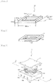
- the test piece is a square-shaped frame having a thickness of 0.5 mm, a width of 1.0 mm, and an edge length of 54 mm, and the opening of the frame is a square having an edge length of 52 mm. Note that a schematic outline view of the test piece is shown in Figure 1 .
- the ratio of the particles passed when the test piece is compressed by 50% of the initial thickness was measured by the following method for measuring the dustproofness index using the following dustproofness testing instrument. Measurement was performed for the case where particles having a diameter of 0.5 mm (0.5 mm particles) were used and the case where particles having a diameter of 1.0 mm (1.0 mm particles) were used. Further, in the measurement of the dustproofness index, a spacer for forming a step was inserted in each edge of the test piece to form steps as shown in Figure 2 . Note that in Figure 2 , reference numeral 14 denotes a test piece; and reference numeral 122 denotes a spacer for forming a step.
- the spacer 122 for forming a step has a rectangular parallelepiped shape and has a thickness of 0.1 mm, a length of 10 mm, and a width of 1 mm.
- FIG. 3 is a schematic diagram of the dustproofness testing instrument
- Figure 4 is an end view of the sectioned part of the A-A' line of the dustproofness testing instrument.
- reference numeral 1 denotes a dustproofness testing instrument
- reference numeral 11 denotes a ceiling panel
- reference numeral 121 denotes a spacer
- reference numeral 122 denotes a spacer for forming a step
- reference numeral 13 denotes a double-coated pressure-sensitive adhesive tape
- reference numeral 14 denotes a test piece
- reference numeral 15 denotes a testing box
- reference character 16a denotes a through hole
- reference numeral 16b denotes a through hole
- reference numeral 16c denotes a through hole
- reference numeral 17 denotes an opening
- reference numeral 18 denotes a space.
- the ceiling panel 11 has a substantially rectangular tabular form and has cuts which constitute openings, whose plan views are rectangular (trapezoid).
- the spacer 121 is larger than the opening 17 and has a rectangular tabular form, and it is used for compressing the test piece 14 into a desired thickness.
- the double-coated pressure-sensitive adhesive tape 13 is a frame-shaped double-coated pressure-sensitive adhesive tape which is of a substrate-less type and has a thickness of 80 ⁇ m, and it is used for fixing the spacer 121 to the test piece 14.
- the through hole 16a is connected to a metering pump via a pipe joint.
- the through hole 16b is connected to a differential pressure gauge via a pipe joint.
- the through hole 16c is connected to a needle valve via a pipe joint.
- the space 18 is formed inside the instrument by screwing the ceiling panel 11 with the testing box 15.
- the resulting space 18 is in a substantially rectangular parallelepiped form and may be hermetically sealed.
- the opening 17 is an opening of the space 18.
- the ceiling panel 11 has cuts which constitute openings, whose plan views are rectangular (trapezoid).
- the test piece 14 was attached to the dustproofness testing instrument as follows.
- the spacer 121 was attached below the bottom of the ceiling panel 11 facing the opening 17 so that the spacer 121 faces the entire surface of the opening 17.
- the spacer 121 is larger than the opening 17 and has a rectangular tabular form.
- the test piece 14 was attached via the double-coated pressure-sensitive adhesive tape 13 at a position of the bottom of the spacer 121 facing the opening 17.
- the test piece 14 has a window having a size substantially the same as that of the opening 17.
- the spacer 122 for forming a step was inserted into the lower part of each edge of the test piece 14, and then the ceiling panel 11 was screwed to the testing box 15.
- the test piece 14 was attached to the dustproofness testing instrument.
- the test piece 14 is compressed in a thickness direction by the spacer 121 and the periphery of the opening 17.
- the compression ratio of the test piece 14 was regulated to 50% compression (a state compressed by 50% of the initial thickness) by regulating the thickness of the spacer 121. Note that when the ceiling panel 11 and the testing box 15 are screwed with each other, the space 18 in the testing box is hermetically sealed by the test piece 14, the spacer 122, the double-coated pressure-sensitive adhesive tape 13, and the spacer 121.
- the dustproofness testing instrument to which the test piece had been attached was arranged in a dust box, which was then hermetically sealed.
- the dust box is connected to a dust supply unit and a particle counter.
- the through hole 16b of the dustproofness testing instrument is connected to the particle counter via a pipe joint.
- particles having a predetermined diameter were supplied to the dust box so that the count (number) of particles was allowed to be substantially constant at around 100000 using the dust supply unit and the particle counter both connected to the dust box.
- the count of particles at this time was defined as the number P0 of particles in the atmosphere.
- aspiration was performed at an aspiration rate of 0.5 L/min for 30 minutes using a metering pump connected to the through hole 16a in a state where the needle valve connected to the through hole 16c of the dustproofness testing instrument is closed.
- the number of particles in the space 18 of the dustproofness testing instrument was measured with the particle counter, and the count of particles at this time was defined as the number Pf of particles passing through the foam.
- Dustproofness Index % P 0 ⁇ Pf / P 0 ⁇ 100
- the assemblability was evaluated by measuring “spreadability (0.5 N)” and “spreadability (1.0 N)”.
- a foam was cut in the MD direction to obtain a test piece in a sheet form having a thickness of 0.5 mm, a width of 3 mm, and a length of 30 mm.
- test piece was drawn in the length direction under a load of 0.5 N in a state where an end of the test piece in the length direction was fixed, and the length of the test piece after drawing was measured.
- the "spreadability (0.5 N)" (spreadability under 0.5 N) can be determined to be good when it is 5.0% or less.
- the spreadability (%) was determined in the same manner as in the spreadability (0.5 N) as described above except that the load was set to 1.0 N.
- the "spreadability (1.0 N)" (spreadability under 1.0 N) can be determined to be good when it is 10.0% or less.
- the resin foams of examples are resin foams having a small repulsive stress at 50% compression and a small repulsive stress at 80% compression, and the resin foams have good followability and exhibit excellent dustproofness, particularly exhibit excellent dustproofness even when the resin foams have steps.
- the resin foams of examples are not easily stretched from the evaluation of spreadability in which actual assembling of the resin foams has been assumed. Therefore, the resin foams of examples can be bonded together to size at the time of assembly.
- the foam of comparative example 1 has a low tensile modulus of elasticity, and it is easily stretched from the evaluation of spreadability. Therefore, the foam of comparative example 1 was difficult to bond together to size at the time of assembly.
- the foams of comparative examples 2 and 3 have a large repulsive stress at 50% compression and a large repulsive stress at 80% compression, and they are hard. Therefore, these foams are poor in followability, and it was impossible to obtain sufficient dustproofness (particularly, dustproofness in the case of having steps).
Landscapes
- Chemical & Material Sciences (AREA)
- Organic Chemistry (AREA)
- Engineering & Computer Science (AREA)
- Materials Engineering (AREA)
- Chemical Kinetics & Catalysis (AREA)
- Health & Medical Sciences (AREA)
- Medicinal Chemistry (AREA)
- Polymers & Plastics (AREA)
- General Chemical & Material Sciences (AREA)
- Manufacture Of Porous Articles, And Recovery And Treatment Of Waste Products (AREA)
- Sealing Material Composition (AREA)
- Laminated Bodies (AREA)
Claims (11)
- Mousse de résine ayant une contrainte répulsive, sous une compression de 80 %, de 1,0 à 9,0 N/cm2 et un module de traction d'élasticité de 5,0 à 14,0 MPa, la contrainte répulsive sous une compression de 80 % étant définie comme une contrainte répulsive lorsqu'une mousse de résine est comprimée à 80 % de l'épaisseur initiale, et le module de traction d'élasticité et la contrainte répulsive sous une compression de 80 % étant déterminés conformément au document JIS K6767,
la mousse de résine ayant un diamètre moyen d'alvéole de 15 à 100 µm et une densité apparente de 0,01 à 0,10 g/cm3, le diamètre moyen d'alvéole étant déterminé en capturant une image agrandie d'une partie alvéolaire d'une coupe transversale de la mousse de résine à l'aide d'un microscope, en mesurant la surface de tous les alvéoles visibles sur une surface donnée (1 mm2) de la surface de coupe, en convertissant la surface en diamètre de cercle équivalent, puis en en calculant la moyenne pour le nombre d'alvéoles ; et
la mousse de résine comprenant un polypropylène et un vulcanisat thermoplastique oléfinique (TPV). - Mousse de résine selon la revendication 1, la mousse de résine étant formée par les étapes consistant à imprégner une composition de résine avec un gaz inerte et soumettre la composition de résine imprégnée à une décompression.
- Mousse de résine selon la revendication 2, dans laquelle le gaz inerte est le dioxyde de carbone.
- Mousse de résine selon la revendication 2 ou 3, dans laquelle le gaz inerte est dans un état supercritique.
- Mousse de résine selon l'une quelconque des revendications 1 à 4, la mousse de résine ayant une résistance à la rupture de 0,60 à 1,10 MPa, la résistance à la rupture étant déterminée d'après le document JIS K6767.
- Mousse de résine selon l'une quelconque des revendications 1 à 5, la mousse de résine ayant un allongement à la rupture de 50 à 200 %, l'allongement à la rupture étant déterminé d'après le document JIS K6767.
- Mousse de résine selon l'une quelconque des revendications 1 à 6, dans laquelle l'épaisseur de la mousse de résine va de 0,1 à 2,0 mm.
- Matériau d'étanchéité en mousse comprenant une mousse de résine selon l'une quelconque des revendications 1 à 7.
- Matériau d'étanchéité en mousse selon la revendication 8, dans lequel une couche d'adhésif est formée sur la mousse de résine.
- Matériau d'étanchéité en mousse selon la revendication 9, dans lequel la couche d'adhésif est formée par le biais d'une couche pelliculaire.
- Matériau d'étanchéité en mousse selon la revendication 8 ou 9, dans lequel la couche d'adhésif est une couche d'adhésif sensible à la pression.
Applications Claiming Priority (2)
| Application Number | Priority Date | Filing Date | Title |
|---|---|---|---|
| JP2011155357 | 2011-07-14 | ||
| JP2012106973A JP5969260B2 (ja) | 2011-07-14 | 2012-05-08 | 樹脂発泡体、その製造方法、及び発泡シール材 |
Publications (3)
| Publication Number | Publication Date |
|---|---|
| EP2546292A2 EP2546292A2 (fr) | 2013-01-16 |
| EP2546292A3 EP2546292A3 (fr) | 2014-03-26 |
| EP2546292B1 true EP2546292B1 (fr) | 2019-12-04 |
Family
ID=46506247
Family Applications (1)
| Application Number | Title | Priority Date | Filing Date |
|---|---|---|---|
| EP12175904.7A Active EP2546292B1 (fr) | 2011-07-14 | 2012-07-11 | Mousse de résine et matériau d'étanchéité en mousse |
Country Status (6)
| Country | Link |
|---|---|
| US (1) | US20130017391A1 (fr) |
| EP (1) | EP2546292B1 (fr) |
| JP (1) | JP5969260B2 (fr) |
| KR (1) | KR20130009662A (fr) |
| CN (1) | CN102875832A (fr) |
| TW (1) | TWI598275B (fr) |
Families Citing this family (31)
| Publication number | Priority date | Publication date | Assignee | Title |
|---|---|---|---|---|
| JP6039501B2 (ja) * | 2012-05-28 | 2016-12-07 | 日東電工株式会社 | 樹脂発泡体及び発泡部材 |
| JP6039505B2 (ja) * | 2012-05-31 | 2016-12-07 | 日東電工株式会社 | 熱可塑性樹脂発泡体及びその製造方法並びに発泡シール材 |
| US20140259753A1 (en) * | 2013-03-15 | 2014-09-18 | Nike, Inc. | Modified thermoplastic elastomers for increased compatibility with supercritical fluids |
| US9375866B2 (en) | 2013-03-15 | 2016-06-28 | Nike, Inc. | Process for foaming thermoplastic elastomers |
| JP6358825B2 (ja) * | 2013-04-10 | 2018-07-18 | 日東電工株式会社 | 樹脂発泡複合体 |
| JP6533608B2 (ja) * | 2013-04-10 | 2019-06-19 | 日東電工株式会社 | 樹脂発泡複合体 |
| JP2015042708A (ja) * | 2013-08-26 | 2015-03-05 | 日東電工株式会社 | 発泡シート |
| CN103571364A (zh) * | 2013-10-08 | 2014-02-12 | 东莞市雄林新材料科技有限公司 | 一种热熔胶加贴tpu发泡薄膜 |
| CN103881629B (zh) * | 2014-03-19 | 2015-12-09 | 京东方科技集团股份有限公司 | 封框胶、显示面板及显示装置 |
| JP6689026B2 (ja) * | 2014-03-26 | 2020-04-28 | 日東電工株式会社 | 樹脂発泡体、発泡部材、及び、タッチパネル搭載機器 |
| US10600076B2 (en) * | 2014-08-14 | 2020-03-24 | Google Llc | Systems and methods for obfuscated audience measurement |
| JP6431546B2 (ja) | 2014-09-30 | 2018-11-28 | 積水化成品工業株式会社 | 樹脂複合体 |
| RU2017144275A (ru) * | 2015-05-19 | 2019-06-19 | Басф Се | Изделие, содержащее трубчатые частицы |
| US10357904B2 (en) | 2015-10-30 | 2019-07-23 | Nike, Inc. | Method of foaming an injection molded precursor |
| US10308779B2 (en) | 2015-10-30 | 2019-06-04 | Nike, Inc. | Method of foaming a milled precursor |
| CN105694430B (zh) * | 2016-03-04 | 2019-02-15 | 安徽天安新材料有限公司 | Tpu发泡材料及其制备方法 |
| US11194426B2 (en) | 2016-10-27 | 2021-12-07 | Lg Chem, Ltd. | Polymer foam adhesive tape and pressure-sensitive type touch panel comprising the same |
| CN109923187B (zh) * | 2016-10-27 | 2021-12-07 | 株式会社Lg化学 | 聚合物泡沫粘合带和包括其的压敏型触摸面板 |
| TWI761525B (zh) | 2017-06-01 | 2022-04-21 | 荷蘭商耐克創新有限合夥公司 | 使用發泡粒子製備物件的方法 |
| JP6907764B2 (ja) * | 2017-06-30 | 2021-07-21 | 三菱ケミカル株式会社 | 積層発泡断熱シート、成形体及び積層発泡断熱シートの製造方法 |
| JP6955947B2 (ja) * | 2017-09-29 | 2021-10-27 | 積水化学工業株式会社 | 積層体 |
| JP6974096B2 (ja) * | 2017-09-29 | 2021-12-01 | 積水化学工業株式会社 | 積層体 |
| CN108034373B (zh) * | 2017-12-15 | 2020-05-26 | 京东方科技集团股份有限公司 | 封框胶及其制备方法、显示面板及其制备方法 |
| US11976185B2 (en) * | 2018-03-28 | 2024-05-07 | Nok Corporation | Rubber composition |
| CN109649839A (zh) * | 2018-11-13 | 2019-04-19 | 惠州市华星光电技术有限公司 | 用于显示面板的垫片和包装盒 |
| CN115956737B (zh) | 2018-12-06 | 2025-12-02 | 耐克创新有限合伙公司 | 利用泡沫颗粒制造物品的方法 |
| WO2020208946A1 (fr) * | 2019-04-10 | 2020-10-15 | 日東電工株式会社 | Objet en mousse ignifuge et élément en mousse |
| WO2020230907A1 (fr) | 2019-05-14 | 2020-11-19 | ニチアス株式会社 | Matériau poreux |
| CN114945458A (zh) | 2019-11-19 | 2022-08-26 | 耐克创新有限合伙公司 | 制造具有泡沫颗粒的物品的方法 |
| JP7552108B2 (ja) * | 2020-07-08 | 2024-09-18 | Mccアドバンスドモールディングス株式会社 | 防食用ラミネートフィルムおよび防食テープ |
| CN112662060B (zh) * | 2020-12-18 | 2022-11-04 | 广东盛路通信有限公司 | 一种龙伯透镜天线介质材料及其制备方法和应用 |
Family Cites Families (8)
| Publication number | Priority date | Publication date | Assignee | Title |
|---|---|---|---|---|
| US20050053779A1 (en) * | 2003-08-22 | 2005-03-10 | Nitto Denko Corporation | Foamed dustproof material and dustproof structure using foamed dustproof material |
| JP4563109B2 (ja) | 2003-08-22 | 2010-10-13 | 日東電工株式会社 | 発泡防塵材の製造方法、および発泡防塵材が用いられた防塵構造の製造方法 |
| JP4378624B2 (ja) | 2004-02-10 | 2009-12-09 | 株式会社イノアックコーポレーション | シール部材の製造方法 |
| JP5121243B2 (ja) * | 2006-03-30 | 2013-01-16 | Jsr株式会社 | ポリオレフィン系樹脂発泡体とその製造方法 |
| JP5153110B2 (ja) * | 2006-10-02 | 2013-02-27 | 日東電工株式会社 | ポリオレフィン系樹脂発泡体とその製造方法 |
| JP5289871B2 (ja) * | 2007-09-21 | 2013-09-11 | 日東電工株式会社 | 微細セル構造を有する発泡防塵材 |
| JP5123021B2 (ja) * | 2008-03-28 | 2013-01-16 | 積水化成品工業株式会社 | ポリプロピレン系樹脂発泡体の製造方法及びポリプロピレン系樹脂発泡体 |
| JP5856448B2 (ja) * | 2010-12-14 | 2016-02-09 | 日東電工株式会社 | 樹脂発泡体及び発泡シール材 |
-
2012
- 2012-05-08 JP JP2012106973A patent/JP5969260B2/ja active Active
- 2012-07-11 TW TW101124998A patent/TWI598275B/zh not_active IP Right Cessation
- 2012-07-11 EP EP12175904.7A patent/EP2546292B1/fr active Active
- 2012-07-12 KR KR20120076025A patent/KR20130009662A/ko not_active Ceased
- 2012-07-13 CN CN2012102440558A patent/CN102875832A/zh active Pending
- 2012-07-13 US US13/548,619 patent/US20130017391A1/en not_active Abandoned
Non-Patent Citations (1)
| Title |
|---|
| None * |
Also Published As
| Publication number | Publication date |
|---|---|
| TW201313574A (zh) | 2013-04-01 |
| EP2546292A3 (fr) | 2014-03-26 |
| CN102875832A (zh) | 2013-01-16 |
| KR20130009662A (ko) | 2013-01-23 |
| EP2546292A2 (fr) | 2013-01-16 |
| JP2013036026A (ja) | 2013-02-21 |
| TWI598275B (zh) | 2017-09-11 |
| US20130017391A1 (en) | 2013-01-17 |
| JP5969260B2 (ja) | 2016-08-17 |
Similar Documents
| Publication | Publication Date | Title |
|---|---|---|
| EP2546292B1 (fr) | Mousse de résine et matériau d'étanchéité en mousse | |
| US9150716B2 (en) | Resin foam and foam sealing material | |
| EP2543698B1 (fr) | Mousse d'élastomère de polyester et matériau en mousse | |
| US8846774B2 (en) | Resin composition for polyolefin resin foam, polyolefin resin foam and foamed sealing material | |
| KR101695042B1 (ko) | 도전성을 갖는 수지 발포체 | |
| KR102121184B1 (ko) | 수지 발포체 시트 및 수지 발포 복합체 | |
| KR102130182B1 (ko) | 수지 발포체 및 발포재 | |
| US20150099112A1 (en) | Resin foam and foam sealing material | |
| US20150218422A1 (en) | Resin foam and foam material | |
| WO2013168798A1 (fr) | Mousse de résine et matériau d'étanchéité en mousse | |
| JP6110213B2 (ja) | 熱可塑性樹脂発泡体、発泡シール材及び熱可塑性樹脂発泡体の製造方法 | |
| JP2014015605A (ja) | 樹脂発泡体及び発泡シール材 | |
| KR20150027031A (ko) | 열가소성 수지 발포체 및 발포 시일재 | |
| JP6181248B2 (ja) | 樹脂発泡体、その製造方法、及び発泡シール材 | |
| JP6006350B2 (ja) | 導電性を有する樹脂発泡体 |
Legal Events
| Date | Code | Title | Description |
|---|---|---|---|
| PUAI | Public reference made under article 153(3) epc to a published international application that has entered the european phase |
Free format text: ORIGINAL CODE: 0009012 |
|
| AK | Designated contracting states |
Kind code of ref document: A2 Designated state(s): AL AT BE BG CH CY CZ DE DK EE ES FI FR GB GR HR HU IE IS IT LI LT LU LV MC MK MT NL NO PL PT RO RS SE SI SK SM TR |
|
| AX | Request for extension of the european patent |
Extension state: BA ME |
|
| PUAL | Search report despatched |
Free format text: ORIGINAL CODE: 0009013 |
|
| AK | Designated contracting states |
Kind code of ref document: A3 Designated state(s): AL AT BE BG CH CY CZ DE DK EE ES FI FR GB GR HR HU IE IS IT LI LT LU LV MC MK MT NL NO PL PT RO RS SE SI SK SM TR |
|
| AX | Request for extension of the european patent |
Extension state: BA ME |
|
| RIC1 | Information provided on ipc code assigned before grant |
Ipc: C08J 9/12 20060101AFI20140219BHEP Ipc: C09J 7/02 20060101ALI20140219BHEP |
|
| 17P | Request for examination filed |
Effective date: 20140918 |
|
| RBV | Designated contracting states (corrected) |
Designated state(s): AL AT BE BG CH CY CZ DE DK EE ES FI FR GB GR HR HU IE IS IT LI LT LU LV MC MK MT NL NO PL PT RO RS SE SI SK SM TR |
|
| STAA | Information on the status of an ep patent application or granted ep patent |
Free format text: STATUS: EXAMINATION IS IN PROGRESS |
|
| 17Q | First examination report despatched |
Effective date: 20180815 |
|
| REG | Reference to a national code |
Ref country code: DE Ref legal event code: R079 Ref document number: 602012066138 Country of ref document: DE Free format text: PREVIOUS MAIN CLASS: C08J0009120000 Ipc: C08J0009000000 |
|
| RIC1 | Information provided on ipc code assigned before grant |
Ipc: C08J 9/00 20060101AFI20190619BHEP |
|
| GRAP | Despatch of communication of intention to grant a patent |
Free format text: ORIGINAL CODE: EPIDOSNIGR1 |
|
| STAA | Information on the status of an ep patent application or granted ep patent |
Free format text: STATUS: GRANT OF PATENT IS INTENDED |
|
| INTG | Intention to grant announced |
Effective date: 20190726 |
|
| GRAS | Grant fee paid |
Free format text: ORIGINAL CODE: EPIDOSNIGR3 |
|
| GRAA | (expected) grant |
Free format text: ORIGINAL CODE: 0009210 |
|
| STAA | Information on the status of an ep patent application or granted ep patent |
Free format text: STATUS: THE PATENT HAS BEEN GRANTED |
|
| AK | Designated contracting states |
Kind code of ref document: B1 Designated state(s): AL AT BE BG CH CY CZ DE DK EE ES FI FR GB GR HR HU IE IS IT LI LT LU LV MC MK MT NL NO PL PT RO RS SE SI SK SM TR |
|
| REG | Reference to a national code |
Ref country code: GB Ref legal event code: FG4D |
|
| REG | Reference to a national code |
Ref country code: CH Ref legal event code: EP |
|
| REG | Reference to a national code |
Ref country code: AT Ref legal event code: REF Ref document number: 1209349 Country of ref document: AT Kind code of ref document: T Effective date: 20191215 |
|
| REG | Reference to a national code |
Ref country code: IE Ref legal event code: FG4D |
|
| REG | Reference to a national code |
Ref country code: DE Ref legal event code: R096 Ref document number: 602012066138 Country of ref document: DE |
|
| REG | Reference to a national code |
Ref country code: NL Ref legal event code: MP Effective date: 20191204 |
|
| REG | Reference to a national code |
Ref country code: LT Ref legal event code: MG4D |
|
| PG25 | Lapsed in a contracting state [announced via postgrant information from national office to epo] |
Ref country code: LT Free format text: LAPSE BECAUSE OF FAILURE TO SUBMIT A TRANSLATION OF THE DESCRIPTION OR TO PAY THE FEE WITHIN THE PRESCRIBED TIME-LIMIT Effective date: 20191204 Ref country code: NO Free format text: LAPSE BECAUSE OF FAILURE TO SUBMIT A TRANSLATION OF THE DESCRIPTION OR TO PAY THE FEE WITHIN THE PRESCRIBED TIME-LIMIT Effective date: 20200304 Ref country code: GR Free format text: LAPSE BECAUSE OF FAILURE TO SUBMIT A TRANSLATION OF THE DESCRIPTION OR TO PAY THE FEE WITHIN THE PRESCRIBED TIME-LIMIT Effective date: 20200305 Ref country code: BG Free format text: LAPSE BECAUSE OF FAILURE TO SUBMIT A TRANSLATION OF THE DESCRIPTION OR TO PAY THE FEE WITHIN THE PRESCRIBED TIME-LIMIT Effective date: 20200304 Ref country code: FI Free format text: LAPSE BECAUSE OF FAILURE TO SUBMIT A TRANSLATION OF THE DESCRIPTION OR TO PAY THE FEE WITHIN THE PRESCRIBED TIME-LIMIT Effective date: 20191204 Ref country code: LV Free format text: LAPSE BECAUSE OF FAILURE TO SUBMIT A TRANSLATION OF THE DESCRIPTION OR TO PAY THE FEE WITHIN THE PRESCRIBED TIME-LIMIT Effective date: 20191204 Ref country code: SE Free format text: LAPSE BECAUSE OF FAILURE TO SUBMIT A TRANSLATION OF THE DESCRIPTION OR TO PAY THE FEE WITHIN THE PRESCRIBED TIME-LIMIT Effective date: 20191204 Ref country code: ES Free format text: LAPSE BECAUSE OF FAILURE TO SUBMIT A TRANSLATION OF THE DESCRIPTION OR TO PAY THE FEE WITHIN THE PRESCRIBED TIME-LIMIT Effective date: 20191204 |
|
| PG25 | Lapsed in a contracting state [announced via postgrant information from national office to epo] |
Ref country code: HR Free format text: LAPSE BECAUSE OF FAILURE TO SUBMIT A TRANSLATION OF THE DESCRIPTION OR TO PAY THE FEE WITHIN THE PRESCRIBED TIME-LIMIT Effective date: 20191204 Ref country code: RS Free format text: LAPSE BECAUSE OF FAILURE TO SUBMIT A TRANSLATION OF THE DESCRIPTION OR TO PAY THE FEE WITHIN THE PRESCRIBED TIME-LIMIT Effective date: 20191204 |
|
| PG25 | Lapsed in a contracting state [announced via postgrant information from national office to epo] |
Ref country code: AL Free format text: LAPSE BECAUSE OF FAILURE TO SUBMIT A TRANSLATION OF THE DESCRIPTION OR TO PAY THE FEE WITHIN THE PRESCRIBED TIME-LIMIT Effective date: 20191204 |
|
| PG25 | Lapsed in a contracting state [announced via postgrant information from national office to epo] |
Ref country code: PT Free format text: LAPSE BECAUSE OF FAILURE TO SUBMIT A TRANSLATION OF THE DESCRIPTION OR TO PAY THE FEE WITHIN THE PRESCRIBED TIME-LIMIT Effective date: 20200429 Ref country code: CZ Free format text: LAPSE BECAUSE OF FAILURE TO SUBMIT A TRANSLATION OF THE DESCRIPTION OR TO PAY THE FEE WITHIN THE PRESCRIBED TIME-LIMIT Effective date: 20191204 Ref country code: RO Free format text: LAPSE BECAUSE OF FAILURE TO SUBMIT A TRANSLATION OF THE DESCRIPTION OR TO PAY THE FEE WITHIN THE PRESCRIBED TIME-LIMIT Effective date: 20191204 Ref country code: EE Free format text: LAPSE BECAUSE OF FAILURE TO SUBMIT A TRANSLATION OF THE DESCRIPTION OR TO PAY THE FEE WITHIN THE PRESCRIBED TIME-LIMIT Effective date: 20191204 Ref country code: NL Free format text: LAPSE BECAUSE OF FAILURE TO SUBMIT A TRANSLATION OF THE DESCRIPTION OR TO PAY THE FEE WITHIN THE PRESCRIBED TIME-LIMIT Effective date: 20191204 |
|
| PG25 | Lapsed in a contracting state [announced via postgrant information from national office to epo] |
Ref country code: SM Free format text: LAPSE BECAUSE OF FAILURE TO SUBMIT A TRANSLATION OF THE DESCRIPTION OR TO PAY THE FEE WITHIN THE PRESCRIBED TIME-LIMIT Effective date: 20191204 Ref country code: SK Free format text: LAPSE BECAUSE OF FAILURE TO SUBMIT A TRANSLATION OF THE DESCRIPTION OR TO PAY THE FEE WITHIN THE PRESCRIBED TIME-LIMIT Effective date: 20191204 Ref country code: IS Free format text: LAPSE BECAUSE OF FAILURE TO SUBMIT A TRANSLATION OF THE DESCRIPTION OR TO PAY THE FEE WITHIN THE PRESCRIBED TIME-LIMIT Effective date: 20200404 |
|
| REG | Reference to a national code |
Ref country code: DE Ref legal event code: R097 Ref document number: 602012066138 Country of ref document: DE |
|
| REG | Reference to a national code |
Ref country code: AT Ref legal event code: MK05 Ref document number: 1209349 Country of ref document: AT Kind code of ref document: T Effective date: 20191204 |
|
| PLBE | No opposition filed within time limit |
Free format text: ORIGINAL CODE: 0009261 |
|
| STAA | Information on the status of an ep patent application or granted ep patent |
Free format text: STATUS: NO OPPOSITION FILED WITHIN TIME LIMIT |
|
| PG25 | Lapsed in a contracting state [announced via postgrant information from national office to epo] |
Ref country code: DK Free format text: LAPSE BECAUSE OF FAILURE TO SUBMIT A TRANSLATION OF THE DESCRIPTION OR TO PAY THE FEE WITHIN THE PRESCRIBED TIME-LIMIT Effective date: 20191204 |
|
| 26N | No opposition filed |
Effective date: 20200907 |
|
| PG25 | Lapsed in a contracting state [announced via postgrant information from national office to epo] |
Ref country code: AT Free format text: LAPSE BECAUSE OF FAILURE TO SUBMIT A TRANSLATION OF THE DESCRIPTION OR TO PAY THE FEE WITHIN THE PRESCRIBED TIME-LIMIT Effective date: 20191204 Ref country code: PL Free format text: LAPSE BECAUSE OF FAILURE TO SUBMIT A TRANSLATION OF THE DESCRIPTION OR TO PAY THE FEE WITHIN THE PRESCRIBED TIME-LIMIT Effective date: 20191204 Ref country code: SI Free format text: LAPSE BECAUSE OF FAILURE TO SUBMIT A TRANSLATION OF THE DESCRIPTION OR TO PAY THE FEE WITHIN THE PRESCRIBED TIME-LIMIT Effective date: 20191204 |
|
| PG25 | Lapsed in a contracting state [announced via postgrant information from national office to epo] |
Ref country code: IT Free format text: LAPSE BECAUSE OF FAILURE TO SUBMIT A TRANSLATION OF THE DESCRIPTION OR TO PAY THE FEE WITHIN THE PRESCRIBED TIME-LIMIT Effective date: 20191204 |
|
| PG25 | Lapsed in a contracting state [announced via postgrant information from national office to epo] |
Ref country code: MC Free format text: LAPSE BECAUSE OF FAILURE TO SUBMIT A TRANSLATION OF THE DESCRIPTION OR TO PAY THE FEE WITHIN THE PRESCRIBED TIME-LIMIT Effective date: 20191204 |
|
| REG | Reference to a national code |
Ref country code: CH Ref legal event code: PL |
|
| GBPC | Gb: european patent ceased through non-payment of renewal fee |
Effective date: 20200711 |
|
| REG | Reference to a national code |
Ref country code: BE Ref legal event code: MM Effective date: 20200731 |
|
| PG25 | Lapsed in a contracting state [announced via postgrant information from national office to epo] |
Ref country code: CH Free format text: LAPSE BECAUSE OF NON-PAYMENT OF DUE FEES Effective date: 20200731 Ref country code: LI Free format text: LAPSE BECAUSE OF NON-PAYMENT OF DUE FEES Effective date: 20200731 Ref country code: LU Free format text: LAPSE BECAUSE OF NON-PAYMENT OF DUE FEES Effective date: 20200711 Ref country code: GB Free format text: LAPSE BECAUSE OF NON-PAYMENT OF DUE FEES Effective date: 20200711 Ref country code: FR Free format text: LAPSE BECAUSE OF NON-PAYMENT OF DUE FEES Effective date: 20200731 |
|
| PG25 | Lapsed in a contracting state [announced via postgrant information from national office to epo] |
Ref country code: BE Free format text: LAPSE BECAUSE OF NON-PAYMENT OF DUE FEES Effective date: 20200731 |
|
| PG25 | Lapsed in a contracting state [announced via postgrant information from national office to epo] |
Ref country code: IE Free format text: LAPSE BECAUSE OF NON-PAYMENT OF DUE FEES Effective date: 20200711 |
|
| PG25 | Lapsed in a contracting state [announced via postgrant information from national office to epo] |
Ref country code: TR Free format text: LAPSE BECAUSE OF FAILURE TO SUBMIT A TRANSLATION OF THE DESCRIPTION OR TO PAY THE FEE WITHIN THE PRESCRIBED TIME-LIMIT Effective date: 20191204 Ref country code: MT Free format text: LAPSE BECAUSE OF FAILURE TO SUBMIT A TRANSLATION OF THE DESCRIPTION OR TO PAY THE FEE WITHIN THE PRESCRIBED TIME-LIMIT Effective date: 20191204 Ref country code: CY Free format text: LAPSE BECAUSE OF FAILURE TO SUBMIT A TRANSLATION OF THE DESCRIPTION OR TO PAY THE FEE WITHIN THE PRESCRIBED TIME-LIMIT Effective date: 20191204 |
|
| PG25 | Lapsed in a contracting state [announced via postgrant information from national office to epo] |
Ref country code: MK Free format text: LAPSE BECAUSE OF FAILURE TO SUBMIT A TRANSLATION OF THE DESCRIPTION OR TO PAY THE FEE WITHIN THE PRESCRIBED TIME-LIMIT Effective date: 20191204 |
|
| PGFP | Annual fee paid to national office [announced via postgrant information from national office to epo] |
Ref country code: DE Payment date: 20230531 Year of fee payment: 12 |
|
| REG | Reference to a national code |
Ref country code: DE Ref legal event code: R119 Ref document number: 602012066138 Country of ref document: DE |
|
| PG25 | Lapsed in a contracting state [announced via postgrant information from national office to epo] |
Ref country code: DE Free format text: LAPSE BECAUSE OF NON-PAYMENT OF DUE FEES Effective date: 20250201 |