EP2546024A1 - Drehmomentabgestütztes Bearbeitungswerkzeug für eine mehrspindlige Werkzeugmaschine - Google Patents
Drehmomentabgestütztes Bearbeitungswerkzeug für eine mehrspindlige Werkzeugmaschine Download PDFInfo
- Publication number
- EP2546024A1 EP2546024A1 EP11173399A EP11173399A EP2546024A1 EP 2546024 A1 EP2546024 A1 EP 2546024A1 EP 11173399 A EP11173399 A EP 11173399A EP 11173399 A EP11173399 A EP 11173399A EP 2546024 A1 EP2546024 A1 EP 2546024A1
- Authority
- EP
- European Patent Office
- Prior art keywords
- heads
- machining
- head
- machining tool
- tool according
- Prior art date
- Legal status (The legal status is an assumption and is not a legal conclusion. Google has not performed a legal analysis and makes no representation as to the accuracy of the status listed.)
- Granted
Links
Images


Classifications
-
- B—PERFORMING OPERATIONS; TRANSPORTING
- B23—MACHINE TOOLS; METAL-WORKING NOT OTHERWISE PROVIDED FOR
- B23Q—DETAILS, COMPONENTS, OR ACCESSORIES FOR MACHINE TOOLS, e.g. ARRANGEMENTS FOR COPYING OR CONTROLLING; MACHINE TOOLS IN GENERAL CHARACTERISED BY THE CONSTRUCTION OF PARTICULAR DETAILS OR COMPONENTS; COMBINATIONS OR ASSOCIATIONS OF METAL-WORKING MACHINES, NOT DIRECTED TO A PARTICULAR RESULT
- B23Q5/00—Driving or feeding mechanisms; Control arrangements therefor
- B23Q5/02—Driving main working members
- B23Q5/04—Driving main working members rotary shafts, e.g. working-spindles
- B23Q5/043—Accessories for spindle drives
-
- B—PERFORMING OPERATIONS; TRANSPORTING
- B23—MACHINE TOOLS; METAL-WORKING NOT OTHERWISE PROVIDED FOR
- B23Q—DETAILS, COMPONENTS, OR ACCESSORIES FOR MACHINE TOOLS, e.g. ARRANGEMENTS FOR COPYING OR CONTROLLING; MACHINE TOOLS IN GENERAL CHARACTERISED BY THE CONSTRUCTION OF PARTICULAR DETAILS OR COMPONENTS; COMBINATIONS OR ASSOCIATIONS OF METAL-WORKING MACHINES, NOT DIRECTED TO A PARTICULAR RESULT
- B23Q3/00—Devices holding, supporting, or positioning work or tools, of a kind normally removable from the machine
- B23Q3/155—Arrangements for automatic insertion or removal of tools, e.g. combined with manual handling
- B23Q3/157—Arrangements for automatic insertion or removal of tools, e.g. combined with manual handling of rotary tools
- B23Q3/15786—Arrangements for automatic insertion or removal of tools, e.g. combined with manual handling of rotary tools a plurality of tools being inserted simultaneously in a plurality of spindles directly from a storage device, i.e. without using transfer devices
-
- B—PERFORMING OPERATIONS; TRANSPORTING
- B23—MACHINE TOOLS; METAL-WORKING NOT OTHERWISE PROVIDED FOR
- B23Q—DETAILS, COMPONENTS, OR ACCESSORIES FOR MACHINE TOOLS, e.g. ARRANGEMENTS FOR COPYING OR CONTROLLING; MACHINE TOOLS IN GENERAL CHARACTERISED BY THE CONSTRUCTION OF PARTICULAR DETAILS OR COMPONENTS; COMBINATIONS OR ASSOCIATIONS OF METAL-WORKING MACHINES, NOT DIRECTED TO A PARTICULAR RESULT
- B23Q39/00—Metal-working machines incorporating a plurality of sub-assemblies, each capable of performing a metal-working operation
- B23Q39/02—Metal-working machines incorporating a plurality of sub-assemblies, each capable of performing a metal-working operation the sub-assemblies being capable of being brought to act at a single operating station
-
- B—PERFORMING OPERATIONS; TRANSPORTING
- B23—MACHINE TOOLS; METAL-WORKING NOT OTHERWISE PROVIDED FOR
- B23Q—DETAILS, COMPONENTS, OR ACCESSORIES FOR MACHINE TOOLS, e.g. ARRANGEMENTS FOR COPYING OR CONTROLLING; MACHINE TOOLS IN GENERAL CHARACTERISED BY THE CONSTRUCTION OF PARTICULAR DETAILS OR COMPONENTS; COMBINATIONS OR ASSOCIATIONS OF METAL-WORKING MACHINES, NOT DIRECTED TO A PARTICULAR RESULT
- B23Q39/00—Metal-working machines incorporating a plurality of sub-assemblies, each capable of performing a metal-working operation
- B23Q2039/002—Machines with twin spindles
Definitions
- the invention relates to a torque-based machining tool, in particular a Winkelbohrkopf- or milling head tool, for a multi-spindle machine tool.
- the problem with the current systems is the lack of changeover accuracy of the drill head finding, which results in a misalignment of the angle drill head.
- the rigidity of the torque support of the angle drill or Fräskopfkopfs on the work spindle box is very low.
- the entire radial load relative to the machine spindle must be absorbed by the machine spindle. This is often problematic with higher machining forces, as due to the large length of the angle drilling or milling heads high bending moments act on the machine spindle, resulting in corresponding compliances and displacements, which in turn adversely affect the processing performance and quality.
- the torque support ("indexing") of the drill heads characterized in that the housings of the processing heads are non-rotatably connected.
- this solid connection for example in the form of a rigid connection arm, the machining forces occurring now absorbed by the two widely spaced work spindles, so that relative to the machine spindles, the bending moments are significantly reduced.
- This causes a drastic improvement in processing performance and processing quality.
- This combination of machining heads causes a very precise indexing or alignment of the machining heads, because - compared to the previous torque support - now the lever of the Bohrkopfindex ist is many times longer and because the spindle interface is many times more accurate.
- the currently usual machine-side device for Bohrkopfindex ist can be completely eliminated, since only the work spindles via the connecting arm cause the alignment of the drill head.
- the machining heads may each be connected in pairs to achieve the desired indexing and support effect.
- the two processing heads can either be at a fixed distance, so rigid, be connected to each other or be freely slidably mounted to each other in the direction of spacing, thereby allowing a length compensation between the two processing heads.
- This length compensation is required to store the two machining heads in two adjacent tool storage locations in the normal chain magazine, without having to make a change to it.
- the distance of the tool axes in the tool magazine is not constant, but changes according to the curves of the tool magazine.
- the invention is not limited to a torque-based double tool with at least two machining heads, but also relates to a torque-based simple tool with only a single machining head and another head having an idle gear for the other work spindle, wherein the housing of the machining head for torque support of the machining head and the other head are connected to each other non-rotatably.
- processing tool 1 comprises two angle drill heads 2 for torque-based attachment to parallel spindles 11 (FIG. Fig. 2 ) a here only schematically indicated multi-spindle machine tool 10 for machining of workpieces.
- the output spindles of the angle drill heads 2 are designated 3 .
- the angle drill heads 2 each have an angle gear (not shown), which is accommodated in a housing 4 .
- the angle drill heads 2 are driven and held by the normal work spindle side Tool change interface of the machine tool 10.
- the housing 4 of the two angle drill heads 2 are interconnected by a bow-shaped connecting arm 5 .
- the connecting arm 5 is designed as a telescopic extension with two arm parts 5a, 5b respectively fastened to a housing 4, which are guided freely displaceable in the longitudinal direction (double arrow 6) .
- Fig. 2 is the machining tool 1 with its two angle heads 2 attached to the two work spindles 11, whereby the two housing 4 of the angle drilling heads 2 are mutually torque-supported by the rigid connection arm 5.
- the torque support ("indexing") of the two angle heads 2 is not locally in the region of the respective spindle interface, but by means of the connecting arm 5 via the other work spindle. The occurring machining forces are absorbed by the two widely spaced work spindles 11, so that based on the work spindles 11, the bending moments are substantially reduced.
- the free longitudinal displacement of the two arm parts 5a, 5b allows a length compensation in the connecting arm 5.
- a length compensation is required to the machining tool 1 with its two angle heads 2 in two tool storage spaces 41 of a normal tool chain magazine 40 (FIGS. Fig. 4 ), without having to make a change to it.
- FIGS. 4a to 4c the axial spacing of the tool depositing places 41 in the tool magazine 40 is not constant, but changes according to the curves of the tool magazine 40.
- machining tool 1 the housing 4 of the right angle drill head 2, as indicated by the double arrow 6, on a connecting arm 50 of the housing 4 of the left angle drill head 2 linearly displaceable, but mounted non-rotatably.
- the housing 4 of the two angle drilling heads 2 are each mounted linearly displaceable on a connecting member 60 , but non-rotatably, as indicated by the two double arrows 6.
- machining tool 1 the housing 4 of the two angle drilling heads 2 via a Parallelogrammauszug 70 linearly displaceable, but mounted non-rotatably, as indicated by the double arrow 6.
- machining tool 1 the housing 4 of the two angle drill heads 2 via a scissors extension 80 linearly displaceable, but mounted non-rotatably, as indicated by the double arrow 6.
- the two scissor arms 81a, 81b are pivotally connected to each other at 82 , wherein the one scissor arm 81a is fixedly connected to both housings 4 and the other scissor arm 81 b is articulated respectively on slides 83 , which are guided in the double arrow direction 84 respectively on the housings 4 transversely ,
- Fig. 9 shows a machining tool 1 with two milling heads 2, in whose bearing or gears (not shown) a cutter shaft 90 is rotatably mounted.
- the housing 4 of the two milling heads 2 are connected to each other non-rotatably and thereby mutually supported torque.
- the two milling heads 2 are driven and held on two work spindles 11 of the machine tool 10.
- the milling shaft 90 can optionally be driven on one side via only one of the two milling heads 2 or on both sides via both milling heads 2. In the former case, the milling shaft 90 can be mounted axially displaceable in the non-driven milling head 2 for a length compensation.
Landscapes
- Engineering & Computer Science (AREA)
- Mechanical Engineering (AREA)
- Drilling And Boring (AREA)
Abstract
Description
- Die Erfindung betrifft ein drehmomentabgestütztes Bearbeitungswerkzeug, insbesondere ein Winkelbohrkopf- oder Fräskopf-Werkzeug, für eine mehrspindlige Werkzeugmaschine.
- An mehrspindligen Werkzeugmaschinen, wie z.B. Fräsmaschinen und Bearbeitungszentren, werden zur Herstellung von Bohrungen oder Flächen, die bezogen auf die Maschinenachsen rechtwinklig oder schräg liegen, vielfach Winkelbohr- oder Fräsköpfe eingesetzt. Diese bestehen aus einem Winkelgetriebe, das in einem Gehäuse aufgenommen ist, welches stationär am Arbeitsspindelkasten der Werkzeugmaschine drehmomentabgestützt ("indexiert") wird. Damit wird die Winkellage der Abtriebsspindel des Winkelbohr- oder Fräskopfes bestimmt. Angetrieben und gehalten wird der Winkelbohr- oder Fräskopf über die normale Arbeitsspindelschnittstelle der Werkzeugmaschine. Bei Werkzeugmaschinen mit automatischem Werkzeugwechsel erfolgt auch der Wechsel des Winkelbohr- oder Fräskopfkopfs ebenfalls automatisch, wobei der komplette Winkelbohr- oder Fräskopfkopf im Magazin abgelegt wird. Dazu wird über die Drehmomentstütze ("Indexierung") des Winkelbohr- oder Fräskopfs eine Verdrehsicherung aktiviert, damit sich der Winkelbohr- bzw. Fräskopf im Magazin nicht verdreht.
- Problematisch bei den derzeitigen Systemen ist zum einen die mangelnde Einwechselgenauigkeit der Bohrkopfindexierung, die sich in einer Fehlstellung des Winkelbohrkopfs auswirkt. Zum anderen ist die Steifigkeit der Drehmomentabstützung des Winkelbohr- oder Fräskopfkopfs am Arbeitsspindelkasten sehr gering. Die komplette radiale Belastung bezogen auf die Maschinenarbeitsspindel muss durch die Maschinenarbeitsspindel aufgenommen werden. Dies ist bei höheren Bearbeitungskräften oft problematisch, da aufgrund der großen Baulänge der Winkelbohr- oder Fräsköpfe hohe Biegemomente auf die Maschinenarbeitsspindel wirken, was sich in entsprechenden Nachgiebigkeiten und Verlagerungen auswirkt, die wiederum die Bearbeitungsleistung und -qualität negativ beeinflussen.
- Es ist demgegenüber die Aufgabe der Erfindung, ein drehmomentabgestütztes Bearbeitungswerkzeug bereitzustellen, das eine höhere Steifigkeit der Drehmomentabstützung aufweist.
- Diese Aufgabe wird erfindungsgemäß durch ein drehmomentabgestütztes Bearbeitungswerkzeug mit den Merkmalen von Anspruch 1 gelöst.
- Erfindungsgemäß erfolgt bei mehrspindligen Werkzeugmaschinen die Drehmomentabstützung ("Indexierung") der Bohrköpfe dadurch, dass die Gehäuse der Bearbeitungsköpfe unverdrehbar miteinander verbunden sind. Durch diese feste Verbindung, z.B. in Form eines biegesteifen Verbindungsarms, werden die auftretenden Bearbeitungskräfte nun durch die beiden weit auseinander liegenden Arbeitsspindeln aufgenommen, so dass bezogen auf die Maschinenarbeitsspindeln die Biegemomente wesentlich reduziert werden. Dies bewirkt eine drastische Verbesserung der Bearbeitungsleistung und Bearbeitungsqualität. Diese Verbindung von Bearbeitungsköpfen bewirkt eine sehr exakte Indexierung bzw. Ausrichtung der Bearbeitungsköpfe, weil― im Vergleich zur bisherigen Drehmomentabstützung ― nunmehr der Hebel der Bohrkopfindexierung um ein Vielfaches länger ist und weil die Spindelschnittstelle um ein Vielfaches genauer ist. Die derzeit übliche maschinenseitige Einrichtung zur Bohrkopfindexierung kann komplett entfallen, da lediglich die Arbeitsspindeln über den Verbindungsarm die Ausrichtung des Bohrkopfs bewirken.
- Bei 4- oder höherspindligen Maschinen können vorzugsweise jeweils die Bearbeitungsköpfe paarweise miteinander verbunden werden, um den gewünschten Indexierungs- und Abstützungseffekt zu erzielen.
- Die beiden Bearbeitungsköpfe können entweder in einem festen Abstand, also starr, miteinander verbunden sein oder aber zueinander in Abstandsrichtung frei verschiebbar gelagert sein, um dadurch einen Längenausgleich zwischen den beiden Bearbeitungsköpfe zu ermöglichen. Dieser Längenausgleich ist erforderlich, um die beiden Bearbeitungsköpfe in zwei benachbarten Werkzeugablageplätzen im normalen Kettenmagazin ablegen zu können, ohne eine Veränderung daran vornehmen zu müssen. Der Abstand der Werkzeugachsen im Werkzeugmagazin ist nicht konstant, sondern verändert sich entsprechend der Kurven des Werkzeugmagazins.
- Die Erfindung ist dabei nicht auf ein drehmomentabgestütztes Doppelwerkzeug mit mindestens zwei Bearbeitungsköpfen beschränkt, sondern betrifft auch ein drehmomentabgestütztes Einfachwerkzeug mit nur einem einzigen Bearbeitungskopf und mit einem weiteren Kopf, der ein Leerlaufgetriebe für die andere Arbeitsspindel aufweist, wobei zur Drehmomentabstützung des Bearbeitungskopfes die Gehäuse des Bearbeitungskopfes und des weiteren Kopfes miteinander unverdrehbar verbunden sind.
- Weitere Vorteile der Erfindung ergeben sich aus der Beschreibung und der Zeichnung. Ebenso können die vorstehend genannten und die noch weiter aufgeführten Merkmale erfindungsgemäß jeweils einzeln für sich oder zu mehreren in beliebigen Kombinationen Verwendung finden. Die gezeigten und beschriebenen Ausführungsformen sind nicht als abschließende Aufzählung zu verstehen, sondern haben vielmehr beispielhaften Charakter für die Schilderung der Erfindung. Die Erfindung ist in den Figuren schematisch dargestellt, so dass die wesentlichen Merkmale der Erfindung gut zu erkennen ist. Die Darstellungen sind nicht notwendigerweise maßstäblich zu verstehen.
- Es zeigt:
- Fig. 1
- das erfindungsgemäße Bearbeitungswerkzeug mit zwei gehäuseseitig verschiebbar, aber unverdrehbar miteinander verbundenen Winkel-bohrköpfen;
- Fig. 2
- schematisch eine Werkzeugmaschine mit zwei Arbeitsspindeln, an de-nen das erfindungsgemäße Bearbeitungswerkzeug drehmomentabge-stützt befestigt ist;
- Fig. 3
- schematisch eine Werkzeugmaschine mit vier Arbeitsspindeln, an de-nen zwei erfindungsgemäße Bearbeitungswerkzeuge jeweils drehmo-mentabgestützt befestigt sind;
- Fign. 4a-4c
- ein Werkzeugkettenmagazin zur Aufnahme des erfindungsgemäßen Bearbeitungswerkzeugs in verschiedenen Kurvenabschnitten;
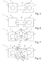
- Fign. 5-8
- schematisch weitere Ausführungsformen von zwei gehäuseseitig ver-schiebbar, aber unverdrehbar miteinander verbundenen Winkelbohr-köpfen; und
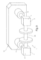
- Fig. 9
- eine noch weitere Ausführungsform eines erfindungsgemäßen Bearbei-tungswerkzeugs mit einer Fräswelle.
- Das in
Fig. 1 gezeigte Bearbeitungswerkzeug 1 umfasst zwei Winkelbohrköpfe 2 zur drehmomentabgestützten Befestigung an parallelen Arbeitsspindeln 11 (Fig. 2 ) einer hier lediglich schematisch angedeuteten mehrspindligen Werkzeugmaschine 10 zur spanenden Bearbeitung von Werkstücken. Die Abtriebsspindeln der Winkelbohrköpfe 2 sind mit 3 bezeichnet. Die Winkelbohrköpfe 2 weisen jeweils ein Winkelgetriebe (nicht gezeigt) auf, das in einem Gehäuse 4 aufgenommen ist. Angetrieben und gehalten werden die Winkelbohrköpfe 2 über die normale arbeitsspindelseitige Werkzeugwechselschnittstelle der Werkzeugmaschine 10. Die Gehäuse 4 der beiden Winkelbohrköpfe 2 sind durch einen bügelförmigen Verbindungsarm 5 miteinander verbunden. Der Verbindungsarm 5 ist als Teleskopauszug mit zwei jeweils an einem Gehäuse 4 befestigten Armteilen 5a, 5b ausgebildet, die in Längsrichtung gegeneinander frei verschiebbar (Doppelpfeil 6) geführt sind. - In
Fig. 2 ist das Bearbeitungswerkzeug 1 mit seinen beiden Winkelbohrköpfen 2 an den beiden Arbeitsspindeln 11 befestigt, wodurch die beiden Gehäuse 4 der Winkelbohrköpfe 2 durch den biegesteifen Verbindungsarm 5 gegenseitig drehmomentabgestützt sind. Mit anderen Worten erfolgt die Drehmomentabstützung ("Indexierung") der beiden Winkelbohrköpfen 2 nicht lokal im Bereich der jeweiligen Spindelschnittstelle, sondern mithilfe des Verbindungsarms 5 über die jeweils andere Arbeitsspindel. Die auftretenden Bearbeitungskräfte werden durch die beiden weit auseinander liegenden Arbeitsspindeln 11 aufgenommen, so dass bezogen auf die Arbeitsspindeln 11 die Biegemomente wesentlich reduziert werden. Dies bewirkt eine drastische Verbesserung der Bearbeitungsleistung und Bearbeitungsqualität sowie auch eine sehr exakte Indexierung bzw. Ausrichtung der Winkelbohrköpfe 2, weil ― im Vergleich zur bisherigen Drehmomentabstützung ― nunmehr der Hebel der Bohrkopfindexierung um ein Vielfaches länger ist und weil die Spindelschnittstelle um ein Vielfaches genauer ist. - Die freie Längsverschiebung der beiden Armteile 5a, 5b ermöglicht einen Längenausgleich im Verbindungsarm 5. Ein solcher Längenausgleich ist erforderlich, um das Bearbeitungswerkzeug 1 mit seinen beiden Winkelbohrköpfen 2 in zwei Werkzeugablageplätzen 41 eines normalen Werkzeugkettenmagazins 40 (
Fig. 4 ) ablegen zu können, ohne eine Veränderung daran vornehmen zu müssen. Wie inFign. 4a bis 4c gezeigt, ist der Achsabstand der Werkzeugablageplätze 41 im Werkzeugmagazin 40 nämlich nicht konstant, sondern verändert sich entsprechend der Kurven des Werkzeugmagazins 40. - Bei dem in
Fig. 5 gezeigten Bearbeitungswerkzeug 1 ist das Gehäuse 4 des rechten Winkelbohrkopfes 2, wie durch den Doppelpfeil 6 angedeutet, an einem Verbindungsarm 50 des Gehäuses 4 des linken Winkelbohrkopfes 2 linear verschiebbar, aber unverdrehbar gelagert. - Bei dem in
Fig. 6 gezeigten Bearbeitungswerkzeug 1 sind die Gehäuse 4 der beiden Winkelbohrköpfe 2 an einem Verbindungsträger 60 jeweils linear verschiebbar, aber unverdrehbar gelagert, wie durch die beiden Doppelpfeile 6 angedeutet ist. - Bei dem in
Fig. 7 gezeigten Bearbeitungswerkzeug 1 sind die Gehäuse 4 der beiden Winkelbohrköpfe 2 über einen Parallelogrammauszug 70 linear verschiebbar, aber unverdrehbar gelagert, wie durch den Doppelpfeil 6 angedeutet ist. - Bei dem in
Fig. 8 gezeigten Bearbeitungswerkzeug 1 sind die Gehäuse 4 der beiden Winkelbohrköpfe 2 über einen Scherenauszug 80 linear verschiebbar, aber unverdrehbar gelagert, wie durch den Doppelpfeil 6 angedeutet ist. Die beiden Scherenarme 81a, 81b sind miteinander bei 82 gelenkig verbunden, wobei der eine Scherenarm 81a an beiden Gehäusen 4 fest angelenkt ist und der andere Scherenarm 81 b jeweils an Schlitten 83 angelenkt ist, die in Doppelpfeilrichtung 84 jeweils an den Gehäusen 4 querbeweglich geführt sind. -
Fig. 9 zeigt ein Bearbeitungswerkzeug 1 mit zwei Fräsköpfen 2, in deren Lager bzw. Getrieben (nicht gezeigt) eine Fräswelle 90 drehbar gelagert ist. Durch die Fräswelle 90 sind die Gehäuse 4 der beiden Fräsköpfe 2 miteinander unverdrehbar verbunden und dadurch gegenseitig drehmomentabgestützt. Die beiden Fräsköpfe 2 sind an zwei Arbeitsspindeln 11 der Werkzeugmaschine 10 angetrieben und gehalten. Die Fräswelle 90 kann wahlweise einseitig über nur einen der beiden Fräsköpfe 2 oder beidseitig über beide Fräsköpfe 2 angetrieben werden. Im ersteren Fall kann für einen Längenausgleich die Fräswelle 90 im nicht angetriebenen Fräskopf 2 axial verschiebbar gelagert sein.
Claims (14)
- Drehmomentabgestütztes Bearbeitungswerkzeug (1) für eine mehrspindlige Werkzeugmaschine (10),
mit mindestens einem, ein Gehäuse (4) aufweisenden Bearbeitungskopf (2) zur Befestigung an einer ersten Arbeitsspindel (11) der mehrspindligen Werkzeugmaschine (10) und
mit mindestens einem, ein Gehäuse (4) aufweisenden weiteren Kopf (2) zur Befestigung an einer parallelen zweiten Arbeitsspindel (11) der mehrspindligen Werkzeugmaschine (10),
wobei zur Drehmomentabstützung das Gehäuse (4) des Bearbeitungskopfes (2) mit dem Gehäuse (4) des weiteren Kopfes (2) unverdrehbar verbunden ist. - Bearbeitungswerkzeug nach Anspruch 1, dadurch gekennzeichnet, dass der weitere Kopf (2) nicht als Bearbeitungskopf ausgebildet ist.
- Bearbeitungswerkzeug nach Anspruch 1, dadurch gekennzeichnet, dass auch der weitere Kopf (2) als Bearbeitungskopf ausgebildet ist.
- Bearbeitungswerkzeug nach Anspruch 3, dadurch gekennzeichnet, dass die Bearbeitungsköpfe (2) jeweils als Winkelbohrköpfe oder als Fräsköpfe ausgebildet sind.
- Bearbeitungswerkzeug nach einem der vorhergehenden Ansprüche, dadurch gekennzeichnet, dass die beiden Köpfe (2) in einem festen Abstand miteinander verbunden sind.
- Bearbeitungswerkzeug nach einem der Ansprüche 1 bis 4, dadurch gekennzeichnet, dass die beiden Köpfe (2) zueinander in ihrer Abstandsrichtung frei verschiebbar (6), aber zueinander unverdrehbar gelagert sind.
- Bearbeitungswerkzeug nach Anspruch 6, dadurch gekennzeichnet, dass der eine Kopf (2) an einem Verbindungsarm (50) des anderen Kopfes (2) verschiebbar gelagert ist.
- Bearbeitungswerkzeug nach Anspruch 6, dadurch gekennzeichnet, dass die beiden Köpfe (2) an einem Verbindungsträger (60) jeweils verschiebbar gelagert sind.
- Bearbeitungswerkzeug nach Anspruch 6, dadurch gekennzeichnet, dass die beiden Köpfe (2) über einen Teleskopauszug (5), einen Parallelogrammauszug (70) oder einen Scherenauszug (80) miteinander verbunden sind.
- Bearbeitungswerkzeug nach einem der vorhergehenden Ansprüche, dadurch gekennzeichnet, dass die beiden Köpfe (2) durch eine in ihnen drehbar gelagerte Welle (90) miteinander verbunden sind.
- Bearbeitungswerkzeug nach Anspruch 10, dadurch gekennzeichnet, dass die Welle (90) einseitig über nur einen oder beidseitig über zwei Köpfe (2) angetrieben ist.
- Bearbeitungswerkzeug nach Anspruch 10 oder 11, dadurch gekennzeichnet, dass die Welle (90) als Fräswelle ausgebildet ist.
- Mehrspindlige Werkzeugmaschine (10) zur spanenden Bearbeitung von Werkstücken, mit mindestens zwei parallelen Arbeitsspindeln (11) und mit mindestens einem Bearbeitungswerkzeug (1) nach einem der vorhergehenden Ansprüche, dessen Köpfe (2) an den Arbeitsspindeln (11) befestigt sind.
- Mehrspindlige Werkzeugmaschine nach Anspruch 13, dadurch gekennzeichnet, dass das Bearbeitungswerkzeug (1) in benachbarten Werkzeugablageplätzen (41) eines Werkzeugmagazins (40) ablegbar ist.
Priority Applications (2)
| Application Number | Priority Date | Filing Date | Title |
|---|---|---|---|
| EP20110173399 EP2546024B1 (de) | 2011-07-11 | 2011-07-11 | Drehmomentabgestütztes Bearbeitungswerkzeug für eine mehrspindlige Werkzeugmaschine |
| ES11173399.4T ES2469215T3 (es) | 2011-07-11 | 2011-07-11 | Herramienta de mecanizado con soporte de par de torsión para una máquina herramienta de múltiples husillos |
Applications Claiming Priority (1)
| Application Number | Priority Date | Filing Date | Title |
|---|---|---|---|
| EP20110173399 EP2546024B1 (de) | 2011-07-11 | 2011-07-11 | Drehmomentabgestütztes Bearbeitungswerkzeug für eine mehrspindlige Werkzeugmaschine |
Publications (2)
| Publication Number | Publication Date |
|---|---|
| EP2546024A1 true EP2546024A1 (de) | 2013-01-16 |
| EP2546024B1 EP2546024B1 (de) | 2014-03-26 |
Family
ID=44785174
Family Applications (1)
| Application Number | Title | Priority Date | Filing Date |
|---|---|---|---|
| EP20110173399 Active EP2546024B1 (de) | 2011-07-11 | 2011-07-11 | Drehmomentabgestütztes Bearbeitungswerkzeug für eine mehrspindlige Werkzeugmaschine |
Country Status (2)
| Country | Link |
|---|---|
| EP (1) | EP2546024B1 (de) |
| ES (1) | ES2469215T3 (de) |
Cited By (1)
| Publication number | Priority date | Publication date | Assignee | Title |
|---|---|---|---|---|
| EP3181276A1 (de) * | 2015-12-18 | 2017-06-21 | Anger Machining GmbH | Werkezugmaschine und verfahren zur feinbearbeitung |
Citations (3)
| Publication number | Priority date | Publication date | Assignee | Title |
|---|---|---|---|---|
| US6099449A (en) * | 1996-03-05 | 2000-08-08 | Huller Hille Gmbh | Process and machine tool for machining workpieces with two work spindles |
| DE102008033530A1 (de) * | 2007-07-20 | 2009-02-05 | Biesse S.P.A. | Vorrichtung für elektrische Spannfutter |
| WO2009121343A1 (de) * | 2008-04-02 | 2009-10-08 | Zimmer Guenther | Werkzeugschwenkaggregat mit mindestens einer fremdverstellten achse |
-
2011
- 2011-07-11 EP EP20110173399 patent/EP2546024B1/de active Active
- 2011-07-11 ES ES11173399.4T patent/ES2469215T3/es active Active
Patent Citations (3)
| Publication number | Priority date | Publication date | Assignee | Title |
|---|---|---|---|---|
| US6099449A (en) * | 1996-03-05 | 2000-08-08 | Huller Hille Gmbh | Process and machine tool for machining workpieces with two work spindles |
| DE102008033530A1 (de) * | 2007-07-20 | 2009-02-05 | Biesse S.P.A. | Vorrichtung für elektrische Spannfutter |
| WO2009121343A1 (de) * | 2008-04-02 | 2009-10-08 | Zimmer Guenther | Werkzeugschwenkaggregat mit mindestens einer fremdverstellten achse |
Cited By (2)
| Publication number | Priority date | Publication date | Assignee | Title |
|---|---|---|---|---|
| EP3181276A1 (de) * | 2015-12-18 | 2017-06-21 | Anger Machining GmbH | Werkezugmaschine und verfahren zur feinbearbeitung |
| WO2017103289A1 (de) * | 2015-12-18 | 2017-06-22 | Anger Machining Gmbh | Werkezugmaschine und verfahren zur feinbearbeitung von lagerbohrungen einer lagergasse |
Also Published As
| Publication number | Publication date |
|---|---|
| EP2546024B1 (de) | 2014-03-26 |
| ES2469215T3 (es) | 2014-06-17 |
Similar Documents
| Publication | Publication Date | Title |
|---|---|---|
| DE4237422C2 (de) | Werkstückhaltevorrichtung für auf Werkzeugmaschinen mehrseitig zu bearbeitende Werkstücke | |
| EP2762254B1 (de) | Kurbelwellendreh- und Fräsmaschine | |
| EP2191933A1 (de) | Werkzeugwechsler für Werkzeugmaschinen | |
| DE102013010359B4 (de) | Fräsgruppe zur Bearbeitung von Platten aus Holz oder ähnlichem | |
| EP2835203B1 (de) | Werkzeugmaschine und Verfahren zur spanenden Bearbeitung von Werkstücken mit mindestens zwei separaten Bearbeitungseinheiten | |
| DE102019132255A1 (de) | Werkzeugeinheit | |
| EP1642673B1 (de) | Werkzeugmaschine | |
| DE102018007186B4 (de) | Spannbackensystem | |
| EP2537628B1 (de) | Bearbeitungsmaschine | |
| EP2546024B1 (de) | Drehmomentabgestütztes Bearbeitungswerkzeug für eine mehrspindlige Werkzeugmaschine | |
| DE202004004636U1 (de) | Zentrierspannvorrichtung | |
| DE102021121245A1 (de) | Verzahnungsmaschine, insbesondere Wälzschälmaschine mit Werkzeugwechselsystem | |
| EP2460622A2 (de) | Vorrichtung zum automatischen Werkzeugwechsel | |
| DE2025700A1 (de) | Nutenfräsmaschine· | |
| DE102010033814A1 (de) | Mehrachsenrundtischantrieb, insbesondere für eine Multispindel-Holzfräsmaschine | |
| DE2349700B2 (de) | Einspindelstangenlangdrehautomat | |
| DE10147649C2 (de) | Fräsaggregat | |
| DE19500515B4 (de) | Werkzeugkopf für Rohrgewindeschneidmaschinen | |
| WO1998040189A1 (de) | Vorrichtung zur werkstückzuführung für eine werkzeugmaschine | |
| EP2295177A1 (de) | Werkzeugaggregat und Nutenziehmaschine zum Herstellen von Nuten oder Vertiefungen | |
| DE102016119957A1 (de) | Werkzeug zur Bearbeitung von Bohrungen | |
| EP3072634B1 (de) | Werkzeugrevolver | |
| DE102013003771A1 (de) | Verzahnmaschine zum Bearbeiten eines Werkstücks und Vefahren zum Bearbeiten einer Kurbelwelle | |
| DE69321818T2 (de) | Vorschubschlitten und mit solch einem Schlitten ausgerüstete Räummaschine | |
| DE102018119477B4 (de) | Spindelanordnung für eine Werkzeugmaschine |
Legal Events
| Date | Code | Title | Description |
|---|---|---|---|
| PUAI | Public reference made under article 153(3) epc to a published international application that has entered the european phase |
Free format text: ORIGINAL CODE: 0009012 |
|
| AK | Designated contracting states |
Kind code of ref document: A1 Designated state(s): AL AT BE BG CH CY CZ DE DK EE ES FI FR GB GR HR HU IE IS IT LI LT LU LV MC MK MT NL NO PL PT RO RS SE SI SK SM TR |
|
| AX | Request for extension of the european patent |
Extension state: BA ME |
|
| 17P | Request for examination filed |
Effective date: 20130125 |
|
| GRAP | Despatch of communication of intention to grant a patent |
Free format text: ORIGINAL CODE: EPIDOSNIGR1 |
|
| RIC1 | Information provided on ipc code assigned before grant |
Ipc: B23Q 5/04 20060101ALI20131202BHEP Ipc: B23Q 39/02 20060101ALI20131202BHEP Ipc: B23Q 3/157 20060101AFI20131202BHEP |
|
| INTG | Intention to grant announced |
Effective date: 20131216 |
|
| GRAS | Grant fee paid |
Free format text: ORIGINAL CODE: EPIDOSNIGR3 |
|
| GRAA | (expected) grant |
Free format text: ORIGINAL CODE: 0009210 |
|
| AK | Designated contracting states |
Kind code of ref document: B1 Designated state(s): AL AT BE BG CH CY CZ DE DK EE ES FI FR GB GR HR HU IE IS IT LI LT LU LV MC MK MT NL NO PL PT RO RS SE SI SK SM TR |
|
| REG | Reference to a national code |
Ref country code: GB Ref legal event code: FG4D Free format text: NOT ENGLISH |
|
| REG | Reference to a national code |
Ref country code: CH Ref legal event code: EP |
|
| REG | Reference to a national code |
Ref country code: AT Ref legal event code: REF Ref document number: 658691 Country of ref document: AT Kind code of ref document: T Effective date: 20140415 |
|
| REG | Reference to a national code |
Ref country code: IE Ref legal event code: FG4D Free format text: LANGUAGE OF EP DOCUMENT: GERMAN |
|
| REG | Reference to a national code |
Ref country code: DE Ref legal event code: R096 Ref document number: 502011002520 Country of ref document: DE Effective date: 20140508 |
|
| REG | Reference to a national code |
Ref country code: ES Ref legal event code: FG2A Ref document number: 2469215 Country of ref document: ES Kind code of ref document: T3 Effective date: 20140617 |
|
| PG25 | Lapsed in a contracting state [announced via postgrant information from national office to epo] |
Ref country code: LT Free format text: LAPSE BECAUSE OF FAILURE TO SUBMIT A TRANSLATION OF THE DESCRIPTION OR TO PAY THE FEE WITHIN THE PRESCRIBED TIME-LIMIT Effective date: 20140326 Ref country code: NO Free format text: LAPSE BECAUSE OF FAILURE TO SUBMIT A TRANSLATION OF THE DESCRIPTION OR TO PAY THE FEE WITHIN THE PRESCRIBED TIME-LIMIT Effective date: 20140626 |
|
| REG | Reference to a national code |
Ref country code: NL Ref legal event code: VDEP Effective date: 20140326 |
|
| REG | Reference to a national code |
Ref country code: LT Ref legal event code: MG4D |
|
| PG25 | Lapsed in a contracting state [announced via postgrant information from national office to epo] |
Ref country code: FI Free format text: LAPSE BECAUSE OF FAILURE TO SUBMIT A TRANSLATION OF THE DESCRIPTION OR TO PAY THE FEE WITHIN THE PRESCRIBED TIME-LIMIT Effective date: 20140326 Ref country code: SE Free format text: LAPSE BECAUSE OF FAILURE TO SUBMIT A TRANSLATION OF THE DESCRIPTION OR TO PAY THE FEE WITHIN THE PRESCRIBED TIME-LIMIT Effective date: 20140326 |
|
| PG25 | Lapsed in a contracting state [announced via postgrant information from national office to epo] |
Ref country code: HR Free format text: LAPSE BECAUSE OF FAILURE TO SUBMIT A TRANSLATION OF THE DESCRIPTION OR TO PAY THE FEE WITHIN THE PRESCRIBED TIME-LIMIT Effective date: 20140326 Ref country code: LV Free format text: LAPSE BECAUSE OF FAILURE TO SUBMIT A TRANSLATION OF THE DESCRIPTION OR TO PAY THE FEE WITHIN THE PRESCRIBED TIME-LIMIT Effective date: 20140326 Ref country code: RS Free format text: LAPSE BECAUSE OF FAILURE TO SUBMIT A TRANSLATION OF THE DESCRIPTION OR TO PAY THE FEE WITHIN THE PRESCRIBED TIME-LIMIT Effective date: 20140326 |
|
| PG25 | Lapsed in a contracting state [announced via postgrant information from national office to epo] |
Ref country code: EE Free format text: LAPSE BECAUSE OF FAILURE TO SUBMIT A TRANSLATION OF THE DESCRIPTION OR TO PAY THE FEE WITHIN THE PRESCRIBED TIME-LIMIT Effective date: 20140326 Ref country code: NL Free format text: LAPSE BECAUSE OF FAILURE TO SUBMIT A TRANSLATION OF THE DESCRIPTION OR TO PAY THE FEE WITHIN THE PRESCRIBED TIME-LIMIT Effective date: 20140326 Ref country code: RO Free format text: LAPSE BECAUSE OF FAILURE TO SUBMIT A TRANSLATION OF THE DESCRIPTION OR TO PAY THE FEE WITHIN THE PRESCRIBED TIME-LIMIT Effective date: 20140326 Ref country code: IS Free format text: LAPSE BECAUSE OF FAILURE TO SUBMIT A TRANSLATION OF THE DESCRIPTION OR TO PAY THE FEE WITHIN THE PRESCRIBED TIME-LIMIT Effective date: 20140726 Ref country code: CY Free format text: LAPSE BECAUSE OF FAILURE TO SUBMIT A TRANSLATION OF THE DESCRIPTION OR TO PAY THE FEE WITHIN THE PRESCRIBED TIME-LIMIT Effective date: 20140326 Ref country code: BG Free format text: LAPSE BECAUSE OF FAILURE TO SUBMIT A TRANSLATION OF THE DESCRIPTION OR TO PAY THE FEE WITHIN THE PRESCRIBED TIME-LIMIT Effective date: 20140626 Ref country code: CZ Free format text: LAPSE BECAUSE OF FAILURE TO SUBMIT A TRANSLATION OF THE DESCRIPTION OR TO PAY THE FEE WITHIN THE PRESCRIBED TIME-LIMIT Effective date: 20140326 |
|
| PG25 | Lapsed in a contracting state [announced via postgrant information from national office to epo] |
Ref country code: PL Free format text: LAPSE BECAUSE OF FAILURE TO SUBMIT A TRANSLATION OF THE DESCRIPTION OR TO PAY THE FEE WITHIN THE PRESCRIBED TIME-LIMIT Effective date: 20140326 Ref country code: SK Free format text: LAPSE BECAUSE OF FAILURE TO SUBMIT A TRANSLATION OF THE DESCRIPTION OR TO PAY THE FEE WITHIN THE PRESCRIBED TIME-LIMIT Effective date: 20140326 |
|
| PG25 | Lapsed in a contracting state [announced via postgrant information from national office to epo] |
Ref country code: PT Free format text: LAPSE BECAUSE OF FAILURE TO SUBMIT A TRANSLATION OF THE DESCRIPTION OR TO PAY THE FEE WITHIN THE PRESCRIBED TIME-LIMIT Effective date: 20140728 |
|
| REG | Reference to a national code |
Ref country code: DE Ref legal event code: R097 Ref document number: 502011002520 Country of ref document: DE |
|
| PG25 | Lapsed in a contracting state [announced via postgrant information from national office to epo] |
Ref country code: DK Free format text: LAPSE BECAUSE OF FAILURE TO SUBMIT A TRANSLATION OF THE DESCRIPTION OR TO PAY THE FEE WITHIN THE PRESCRIBED TIME-LIMIT Effective date: 20140326 |
|
| PLBE | No opposition filed within time limit |
Free format text: ORIGINAL CODE: 0009261 |
|
| STAA | Information on the status of an ep patent application or granted ep patent |
Free format text: STATUS: NO OPPOSITION FILED WITHIN TIME LIMIT |
|
| PG25 | Lapsed in a contracting state [announced via postgrant information from national office to epo] |
Ref country code: LU Free format text: LAPSE BECAUSE OF FAILURE TO SUBMIT A TRANSLATION OF THE DESCRIPTION OR TO PAY THE FEE WITHIN THE PRESCRIBED TIME-LIMIT Effective date: 20140711 |
|
| REG | Reference to a national code |
Ref country code: CH Ref legal event code: PL |
|
| 26N | No opposition filed |
Effective date: 20150106 |
|
| REG | Reference to a national code |
Ref country code: DE Ref legal event code: R097 Ref document number: 502011002520 Country of ref document: DE Effective date: 20150106 |
|
| REG | Reference to a national code |
Ref country code: IE Ref legal event code: MM4A |
|
| PG25 | Lapsed in a contracting state [announced via postgrant information from national office to epo] |
Ref country code: LI Free format text: LAPSE BECAUSE OF NON-PAYMENT OF DUE FEES Effective date: 20140731 Ref country code: CH Free format text: LAPSE BECAUSE OF NON-PAYMENT OF DUE FEES Effective date: 20140731 |
|
| PG25 | Lapsed in a contracting state [announced via postgrant information from national office to epo] |
Ref country code: SI Free format text: LAPSE BECAUSE OF FAILURE TO SUBMIT A TRANSLATION OF THE DESCRIPTION OR TO PAY THE FEE WITHIN THE PRESCRIBED TIME-LIMIT Effective date: 20140326 |
|
| PG25 | Lapsed in a contracting state [announced via postgrant information from national office to epo] |
Ref country code: IE Free format text: LAPSE BECAUSE OF NON-PAYMENT OF DUE FEES Effective date: 20140711 |
|
| GBPC | Gb: european patent ceased through non-payment of renewal fee |
Effective date: 20150711 |
|
| PG25 | Lapsed in a contracting state [announced via postgrant information from national office to epo] |
Ref country code: GB Free format text: LAPSE BECAUSE OF NON-PAYMENT OF DUE FEES Effective date: 20150711 Ref country code: MC Free format text: LAPSE BECAUSE OF FAILURE TO SUBMIT A TRANSLATION OF THE DESCRIPTION OR TO PAY THE FEE WITHIN THE PRESCRIBED TIME-LIMIT Effective date: 20140326 Ref country code: SM Free format text: LAPSE BECAUSE OF FAILURE TO SUBMIT A TRANSLATION OF THE DESCRIPTION OR TO PAY THE FEE WITHIN THE PRESCRIBED TIME-LIMIT Effective date: 20140326 |
|
| PG25 | Lapsed in a contracting state [announced via postgrant information from national office to epo] |
Ref country code: MT Free format text: LAPSE BECAUSE OF FAILURE TO SUBMIT A TRANSLATION OF THE DESCRIPTION OR TO PAY THE FEE WITHIN THE PRESCRIBED TIME-LIMIT Effective date: 20140326 Ref country code: GR Free format text: LAPSE BECAUSE OF FAILURE TO SUBMIT A TRANSLATION OF THE DESCRIPTION OR TO PAY THE FEE WITHIN THE PRESCRIBED TIME-LIMIT Effective date: 20140627 |
|
| REG | Reference to a national code |
Ref country code: FR Ref legal event code: PLFP Year of fee payment: 6 |
|
| PG25 | Lapsed in a contracting state [announced via postgrant information from national office to epo] |
Ref country code: TR Free format text: LAPSE BECAUSE OF FAILURE TO SUBMIT A TRANSLATION OF THE DESCRIPTION OR TO PAY THE FEE WITHIN THE PRESCRIBED TIME-LIMIT Effective date: 20140326 Ref country code: BE Free format text: LAPSE BECAUSE OF FAILURE TO SUBMIT A TRANSLATION OF THE DESCRIPTION OR TO PAY THE FEE WITHIN THE PRESCRIBED TIME-LIMIT Effective date: 20140731 Ref country code: HU Free format text: LAPSE BECAUSE OF FAILURE TO SUBMIT A TRANSLATION OF THE DESCRIPTION OR TO PAY THE FEE WITHIN THE PRESCRIBED TIME-LIMIT; INVALID AB INITIO Effective date: 20110711 |
|
| REG | Reference to a national code |
Ref country code: FR Ref legal event code: PLFP Year of fee payment: 7 |
|
| REG | Reference to a national code |
Ref country code: AT Ref legal event code: MM01 Ref document number: 658691 Country of ref document: AT Kind code of ref document: T Effective date: 20160711 |
|
| PG25 | Lapsed in a contracting state [announced via postgrant information from national office to epo] |
Ref country code: AT Free format text: LAPSE BECAUSE OF NON-PAYMENT OF DUE FEES Effective date: 20160711 |
|
| PG25 | Lapsed in a contracting state [announced via postgrant information from national office to epo] |
Ref country code: MK Free format text: LAPSE BECAUSE OF FAILURE TO SUBMIT A TRANSLATION OF THE DESCRIPTION OR TO PAY THE FEE WITHIN THE PRESCRIBED TIME-LIMIT Effective date: 20140326 |
|
| REG | Reference to a national code |
Ref country code: FR Ref legal event code: PLFP Year of fee payment: 8 |
|
| PG25 | Lapsed in a contracting state [announced via postgrant information from national office to epo] |
Ref country code: AL Free format text: LAPSE BECAUSE OF FAILURE TO SUBMIT A TRANSLATION OF THE DESCRIPTION OR TO PAY THE FEE WITHIN THE PRESCRIBED TIME-LIMIT Effective date: 20140326 |
|
| PGFP | Annual fee paid to national office [announced via postgrant information from national office to epo] |
Ref country code: ES Payment date: 20250819 Year of fee payment: 15 |
|
| PGFP | Annual fee paid to national office [announced via postgrant information from national office to epo] |
Ref country code: DE Payment date: 20250728 Year of fee payment: 15 |
|
| PGFP | Annual fee paid to national office [announced via postgrant information from national office to epo] |
Ref country code: IT Payment date: 20250731 Year of fee payment: 15 |
|
| PGFP | Annual fee paid to national office [announced via postgrant information from national office to epo] |
Ref country code: FR Payment date: 20250723 Year of fee payment: 15 |