EP2545866A2 - Medizinisches Schneidinstrument zum Schneiden von Muskeln und Sehnen - Google Patents
Medizinisches Schneidinstrument zum Schneiden von Muskeln und Sehnen Download PDFInfo
- Publication number
- EP2545866A2 EP2545866A2 EP12005051A EP12005051A EP2545866A2 EP 2545866 A2 EP2545866 A2 EP 2545866A2 EP 12005051 A EP12005051 A EP 12005051A EP 12005051 A EP12005051 A EP 12005051A EP 2545866 A2 EP2545866 A2 EP 2545866A2
- Authority
- EP
- European Patent Office
- Prior art keywords
- jaw part
- handle
- cutting
- instrument according
- cutting instrument
- Prior art date
- Legal status (The legal status is an assumption and is not a legal conclusion. Google has not performed a legal analysis and makes no representation as to the accuracy of the status listed.)
- Granted
Links
Images

Classifications
-
- A—HUMAN NECESSITIES
- A61—MEDICAL OR VETERINARY SCIENCE; HYGIENE
- A61B—DIAGNOSIS; SURGERY; IDENTIFICATION
- A61B17/00—Surgical instruments, devices or methods
- A61B17/32—Surgical cutting instruments
- A61B17/320016—Endoscopic cutting instruments, e.g. arthroscopes, resectoscopes
-
- A—HUMAN NECESSITIES
- A61—MEDICAL OR VETERINARY SCIENCE; HYGIENE
- A61B—DIAGNOSIS; SURGERY; IDENTIFICATION
- A61B17/00—Surgical instruments, devices or methods
- A61B17/00008—Vein tendon strippers
-
- A—HUMAN NECESSITIES
- A61—MEDICAL OR VETERINARY SCIENCE; HYGIENE
- A61B—DIAGNOSIS; SURGERY; IDENTIFICATION
- A61B17/00—Surgical instruments, devices or methods
- A61B17/32—Surgical cutting instruments
- A61B17/3205—Excision instruments
-
- A—HUMAN NECESSITIES
- A61—MEDICAL OR VETERINARY SCIENCE; HYGIENE
- A61B—DIAGNOSIS; SURGERY; IDENTIFICATION
- A61B17/00—Surgical instruments, devices or methods
- A61B17/28—Surgical forceps
- A61B17/29—Forceps for use in minimally invasive surgery
- A61B17/295—Forceps for use in minimally invasive surgery combined with cutting implements
-
- A—HUMAN NECESSITIES
- A61—MEDICAL OR VETERINARY SCIENCE; HYGIENE
- A61B—DIAGNOSIS; SURGERY; IDENTIFICATION
- A61B17/00—Surgical instruments, devices or methods
- A61B2017/00969—Surgical instruments, devices or methods used for transplantation
-
- A—HUMAN NECESSITIES
- A61—MEDICAL OR VETERINARY SCIENCE; HYGIENE
- A61B—DIAGNOSIS; SURGERY; IDENTIFICATION
- A61B17/00—Surgical instruments, devices or methods
- A61B17/32—Surgical cutting instruments
- A61B17/320016—Endoscopic cutting instruments, e.g. arthroscopes, resectoscopes
- A61B2017/32004—Endoscopic cutting instruments, e.g. arthroscopes, resectoscopes having a laterally movable cutting member at its most distal end which remains within the contours of said end
Definitions
- the invention relates to a medical cutting instrument for cutting muscles and tendons, comprising a shaft, at the distal end of which a tool consisting of two jaw parts is arranged, one jaw part being designed as a jaw part which is adjustable relative to the other jaw part, and a handle at its proximal end is arranged, wherein the adjustable jaw part and the handle via a shaft mounted in the actuating element in operative connection with each other, that the adjustable jaw part is adjustable by operating the handle between a closed position and an open position of the tool.
- Generic medical cutting instruments are used, for example, for harvesting tendons to use as a graft to replace other damaged tendons.
- a medical cutting instrument for cutting muscles and tendons is known, for example, from the US patent US 253,359 A known. With this known instrument, it is possible to create an incision that exposes a tendon to retrieve this tendon and to separate a piece from the tendon tissue.
- the invention is based on the object to provide a medical cutting instrument of the aforementioned kind that allows a controlled severing of the muscle / tendon tissue if administered subcutaneously with simple handling.
- the solution according to the invention is characterized in that the other jaw part in the plan view is U-shaped so that the two parallel legs of the U are arranged transversely to the instrument longitudinal axis and the opening of the U facing one side of the other jaw part, so that the another jaw part can be pushed from the side onto the muscle / tendon tissue to be severed.
- the inventive design of the open to one side of the other jaw part it is possible to push the rigid jaw part subcutaneously from the side of the muscle / tendon tissue to be cut in order to sever the muscle / tendon tissue terminal.
- a cutting edge is formed, which is preferably arranged to the other jaw part aligned at the distal end of the adjustable jaw part, so that the muscle / tendon tissue arranged between the two jaw parts when closing the adjustable jaw part is automatically cut.
- V-shaped cutting edges are arranged on both jaw parts.
- the V-shaped configuration of the cutting edges causes the tendon to be cut to be first fixed on its outer surface, before finally being in the central area is cut off.
- the cutting edge is formed like a toothed comb, so that the adjustable Mauteil controlled on the previously split muscle / tendon tissue can be placed and this leader holds until the muscle / tendon tissue is cut when closing the jaw parts.
- a lever mechanism is provided which forms a variable stop for closing the two jaws against each other and thus causes the adjustment of the cutting depth.
- a scaling is arranged on the handle in order to be able to cut through the muscle / tendon tissue at a specific depth in a targeted manner.
- the handle is arranged at an angle to the instrument longitudinal axis on the shaft.
- the handle is angled at an angle of 20 ° to the instrument longitudinal axis relative to the shaft.
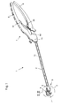
- the illustration Fig. 1 shows a perspective view of a medical cutting instrument 1 for cutting muscles and tendons.
- This formed for example as a punch for removing the Quadrizepssehne cutting instrument 1 has a shaft 2, at the distal end of a two jaw parts 3 and 4 existing tool 5 is arranged, wherein a jaw part 3 is rigid and the other jaw part 4 than about a pivot axis 6 opposite the rigid jaw part 3 pivotable jaw part 4 is formed.
- a handle 7 is arranged, which consists in the illustrated embodiment of two handle parts 8 and 9, wherein a handle part 8 is rigid and the other handle part 9 as about a pivot axis 10 relative to the rigid handle part 8 pivotable handle part. 9 is trained.
- the handle 7 is not arranged in a straight line in extension of the shaft 2 at the proximal end of the shaft 2, but preferably angled at an angle of 20 °.
- this angling the Handle 7 relative to the shaft 2 is better at handling or cutting the Quadrizepssehne better handling and operation of the cutting mechanism possible, since in a linearly elongated arrangement of the handle 7 in extension of the shaft 2 of the patient's body can hinder the operation of the cutting instrument.
- the pivotable jaw part 4 of the tool 5 and the pivotable handle part 9 of the handle 7 are in operative connection with one another via an actuating element 11 mounted in the shaft 2 in such a way that the pivotable jaw part 4 is actuated by actuating the pivotable grip part 9 between a closed position (FIG. Fig. 1 . 3 and 4 ) and a relative to the rigid jaw part 3 pivoted open position ( Fig. 2 ) is adjustable.
- a particularly advantageous guidance and thus positioning of the tendon can be achieved when cutting, resulting in the subcutaneous application of the cutting instrument 1 to a much better cutting result.
- the illustrated pivoting of the jaw part 4 relative to the other jaw part 3 is only one embodiment for mutual adjustment of the jaw parts 3 and 4 to each other.
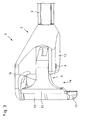
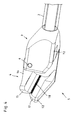
- the construction of the distal-side tool 5 consisting of the parts 3 and 4 is particularly the enlarged detail views of the figures Fig. 2 to 4 refer to.
- the rigid jaw part 3 in plan view is U-shaped so that the two parallel Legs 12 of the U are arranged transversely to the instrument longitudinal axis 13 and the opening 14 of the U to one side of the rigid jaw part 3 has.
- the pivotable jaw part 4 is formed from the top view T-shaped so that the transverse web 15 of the T is arranged parallel to the distal side leg 12 of the U-shaped rigid Mauteils 3 and the longitudinal web 16 is arranged in extension of the actuating element 11.
- the rigid jaw part 3 as open to one side jaw part 3 and the T-shaped design of the pivotable jaw part 4, it is possible to postpone the tool 5 from the side to be cut through the muscle / tendon tissue, so as a controlled terminal To cut through the muscle / tendon tissue to allow.
- a run-on slope 17 is formed at the free end of the distal-side leg 12 of the U-shaped rigid jaw part 3, as shown Fig. 4 can be seen.
- a cutting edge 18 is arranged on the pivotable jaw part 4, which is oriented downwardly toward the rigid jaw part 3 on the distal transverse web 15 of the pivotable jaw part 4 such that the muscle / tendon tissue arranged between the jaw parts 3 and 4 is severed as soon as the pivotable jaw part 4 of the tool 5 is completely closed.
- the cutting edge 18 is formed combed toothed, so that the pivotable Mauteil 4 can be placed on the previously split muscle / tendon tissue and keeps this leader until the muscle / tendon tissue is cut when closing the jaws 3 and 4.
- a lever mechanism 19 is provided for adjusting and adjusting the cutting depth of the handle 7, which forms a variable stop for closing the two jaws 3 and 4 against each other and thus causes the adjustment of the cutting depth.
- an externally readable scale 20 is provided on the handle 7, so that the muscle / tendon tissue can be cut through the operation of the lever mechanism 19 targeted at a certain depth.
- This lever mechanism 19 with the scale 20 together with the comb-like toothed cutting edge 18 allows a very precise adjustment of the depth of cut with simultaneous exact placement of the cut to be performed.
- the rigid jaw part 3 can be subcutaneously pushed onto the muscle / tendon tissue to be severed subcutaneously from the side in order to sever the muscle / tendon tissue terminally can.
Landscapes
- Health & Medical Sciences (AREA)
- Life Sciences & Earth Sciences (AREA)
- Surgery (AREA)
- Molecular Biology (AREA)
- Engineering & Computer Science (AREA)
- Biomedical Technology (AREA)
- Heart & Thoracic Surgery (AREA)
- Medical Informatics (AREA)
- Nuclear Medicine, Radiotherapy & Molecular Imaging (AREA)
- Animal Behavior & Ethology (AREA)
- General Health & Medical Sciences (AREA)
- Public Health (AREA)
- Veterinary Medicine (AREA)
- Orthopedic Medicine & Surgery (AREA)
- Rheumatology (AREA)
- Surgical Instruments (AREA)
Abstract
Description
- Die Erfindung betrifft ein medizinisches Schneidinstrument zum Schneiden von Muskeln und Sehnen, mit einem Schaft, an dessen distalem Ende ein aus zwei Maulteilen bestehendes Werkzeug angeordnet ist, wobei ein Maulteil als gegenüber dem anderen Maulteil verstellbares Maulteil ausgebildet ist, und an dessen proximalem Ende eine Handhabe angeordnet ist, wobei das verstellbare Maulteil und die Handhabe über ein im Schaft gelagertes Betätigungselement derart in Wirkverbindung miteinander stehen, dass das verstellbare Maulteil durch Betätigen der Handhabe zwischen einer geschlossenen Position und einer geöffneten Position des Werkzeugs verstellbar ist.
- Gattungsgemäße medizinisches Schneidinstrumente werden beispielsweise zur Entnahme von Sehnen verwendet, um diese als Transplantat zum Ersatz anderer zerstörter Sehnen zu verwenden.
- Ein medizinisches Schneidinstrument zum Schneiden von Muskeln und Sehnen ist beispielsweise aus dem US-Patent
US 253,359 A bekannt. Mit diesem bekannten Instrument ist es möglich, eine Inzision zu schaffen, die eine Sehne freilegt, diese Sehne zu bergen sowie ein Stück aus dem Sehnengewebe herauszutrennen. - Als Transplantat zum Ersatz des vorderen Kreuzbandes hat sich in der operativen Praxis die Verwendung der Quadrizepssehne bewährt. Bei den bekannten operativen Verfahren zur Entnahme des Quadrizepssehnen-Transplantats wird die Sehne mit einem Skalpell vom Knochen abgetrennt. Nachteilig an diesem bekannten Operationsverfahren zur Entnahme des Quadrizepssehnen-Transplantats ist, dass kein kontrolliertes Durchtrennen der Sehne möglich ist.
- Davon ausgehend liegt der Erfindung die Aufgabe zugrunde, ein medizinisches Schneidinstrument der eingangs genannten Art zu schaffen, das bei einfacher Handhabung ein kontrolliertes Durchtrennen des Muskel-/Sehnengewebes bei subkutaner Anwendung ermöglicht.
- Die Lösung dieser Aufgabenstellung ist erfindungsgemäß gekennzeichnet durch die Merkmale des Anspruchs 1. Vorteilhafte Weiterbildungen der Erfindung sind Gegenstand der Unteransprüche.
- Die erfindungsgemäße Lösung zeichnet sich dadurch aus, dass das andere Maulteil in der Draufsicht U-förmig so ausgebildet ist, dass die beiden parallelen Schenkel des U quer zur Instrumentenlängsachse angeordnet sind und die Öffnung des U zur einer Seite des anderen Maulteils weist, so dass das andere Maulteil von seitlich auf das zu durchtrennende Muskel-/Sehnengewebe aufschiebbar ist.
- Durch die erfindungsgemäße Ausbildung des zu einer Seite hin offenen anderen Maulteils ist es möglich, das starre Maulteil kontrolliert subcutan von der Seite auf das zu durchtrennende Muskel-/Sehnengewebe aufzuschieben, um das Muskel-/Sehnegewebe endständig durchtrennen zu können.
- Gemäß einer praktischen Ausführungsform der Erfindung wird vorgeschlagen, dass zumindest am verstellbaren Maulteil eine Schneidkante ausgebildet ist, die vorzugsweise zum anderen Maulteil hin ausgerichtet am distalen Ende des verstellbaren Maulteils angeordnet ist, so dass das zwischen den beiden Maulteilen angeordnete Muskel-/Sehnengewebe beim Schließen des verstellbaren Maulteils automatisch durchtrennt wird.
- Mit einer bevorzugten Ausführungsform der Erfindung wird vorgeschlagen, dass an beiden Maulteilen V-förmig ausgebildete Schneidkanten angeordnet sind. Die V-förmige Ausgestaltung der Schneidkanten bewirkt, dass die zu schneidende Sehne zuerst an ihrer Außenseite fixiert wird, bevor sie dann endgültig im zentralen Bereich abgeschnitten wird. Durch diese äußere Fixierung wird ein deutlich besseres Schneidergebnis erreicht und ein unerwünschtes Quetschen und dadurch mögliches Verschieben der Sehne beim Schneidvorgang verhindert.
- Weiterhin wird mit der Erfindung vorgeschlagen, dass die Schneidkante kammartig gezahnt ausgebildet ist, so dass das verstellbare Mauteil kontrolliert auf das zuvor gesplittete Muskel-/Sehnengewebe aufgesetzt werden kann und dieses führend hält, bis das Muskel-/Sehnengewebe beim Schließen der Maulteile durchtrennt wird.
- Um das seitliche Aufschieben des starren Maulteils auf das zu durchtrennende Muskel-/Sehnengewebe zu erleichtern, wird erfindungsgemäß vorgeschlagen, dass am freien Ende des distalseitigen Schenkels des U-förmigen anderen Maulteils ein Anlaufschräge ausgebildet ist
- Zur Einstellung und Verstellung der Schneidtiefe wird mit der Erfindung vorgeschlagen, dass im Bereich der Handhabe ein Hebelmechanismus vorgesehen ist, der einen variablen Anschlag für das Schließen der beiden Maulteile gegeneinander ausbildet und so die Verstellung der Schneidtiefe bewirkt.
- Schließlich wird mit der Erfindung vorgeschlagen, dass an der Handhabe eine Skalierung angeordnet ist, um das Muskel-/Sehnengewebe gezielt in einer bestimmten Tiefe durchtrennen zu können.
- Um die Handhabung des erfindungsgemäßen Schneidinstruments zu verbessern und eine sichere Schneidwirkung bzw. Dosierung der Schneidwirkung zu schaffen, wird mit der Erfindung weiterhin vorgeschlagen, dass die Handhabe winklig zur Instrumentenlängsachse am Schaft angeordnet ist. Vorteilhafterweise ist die Handhabe unter einem Winkel von 20° zur Instrumentenlängsachse gegenüber dem Schaft abgewinkelt.
- Durch diese Abwinklung ist bei der Entnahme bzw. beim Abschneiden der Quadrizepssehne eine bessere Handhabung und Betätigung des Schneidmechanismus gegeben, da bei einer linear gestreckten Anordnung der Handhabe in Verlängerung des Schaftes der Körper des Patienten die Betätigung des Schneidinstruments behindern kann.
- Weitere Merkmale und Vorteile der Erfindung ergeben sich anhand der zugehörigen Zeichnungen, in denen ein Ausführungsbeispiel eines erfindungsgemäßen medizinischen Schneidinstruments zum Schneiden von Muskeln und Sehnen nur beispielhaft dargestellt ist, ohne die Erfindung auf dieses Ausführungsbeispiel zu beschränken. In den Zeichnungen zeigt:
- Fig. 1
- eine schematische Seitenansicht eines erfindungsgemäßen medizinischen Schneidinstruments zum Schneiden von Muskeln und Sehnen;
- Fig. 2
- eine vergrößerte Ansicht des Details II gemäß
Fig. 1 , jedoch das Werkzeug im geöffneten Zustand darstellend; - Fig. 3
- eine vergrößerte Draufsicht auf das Detail III gemäß
Fig. 1 und - Fig. 4
- eine Ansicht von hinten-unten der Darstellung gemäß
Fig. 3 . - Die Abbildung
Fig. 1 zeigt eine perspektivische Ansicht eines medizinisches Schneidinstruments 1 zum Schneiden von Muskeln und Sehnen. - Dieses beispielsweise als Stanze zur Entnahme der Quadrizepssehne ausgebildete Schneidinstrument 1 weist einen Schaft 2 auf, an dessen distalem Ende ein aus zwei Maulteilen 3 und 4 bestehendes Werkzeug 5 angeordnet ist, wobei ein Maulteil 3 starr ausgebildet ist und das andere Maulteil 4 als um eine Schwenkachse 6 gegenüber dem starren Maulteil 3 verschwenkbares Maulteil 4 ausgebildet ist. Am proximalem Ende des Schaftes 2 ist eine Handhabe 7 angeordnet, die bei der dargestellten Ausführungsform aus zwei Griffteilen 8 und 9 besteht, wobei ein Griffteil 8 starr ausgebildet ist und das andere Griffteil 9 als um eine Schwenkachse 10 gegenüber dem starren Griffteil 8 verschwenkbares Griffteil 9 ausgebildet ist.
- Wie weiterhin aus
Fig. 1 ersichtlich, ist die Handhabe 7 nicht geradlinig in Verlängerung des Schaftes 2 am proximalen Ende des Schaftes 2 angeordnet, sondern vorzugsweise um einen Winkel von 20° abgewinkelt. Durch diese Abwinklung der Handhabe 7 gegenüber dem Schaft 2 ist bei der Entnahme bzw. beim Abschneiden der Quadrizepssehne eine bessere Handhabung und Betätigung des Schneidmechanismus möglich, da bei einer linear gestreckten Anordnung der Handhabe 7 in Verlängerung des Schaftes 2 der Körper des Patienten die Betätigung des Schneidinstruments behindern kann. - Das verschwenkbare Maulteil 4 des Werkzeugs 5 und das verschwenkbare Griffteil 9 der Handhabe 7 stehen über ein im Schaft 2 gelagertes Betätigungselement 11 derart in Wirkverbindung miteinander, dass das verschwenkbare Maulteil 4 durch Betätigen des verschwenkbaren Griffteils 9 zwischen einer am starren Maulteil 3 anliegenden geschlossenen Position (
Fig. 1 ,3 und4 ) und einer gegenüber dem starren Maulteil 3 verschwenkten offenen Position (Fig. 2 ) verstellbar ist. Durch das starre Maulteil 3 kann eine besonders vorteilhafte Führung und damit Positionierung der Sehne beim Schnitt erreicht werden, was bei der subkutanen Anwendung des Schneidinstrumentes 1 zu einem wesentlich besseren Schneidergebnis führt. - Alternativ zu der dargestellten Ausführungsform des Schneidinstruments 1 mit einem starren Maulteil 3 und einem verschwenkbaren Maulteil 4 ist es selbstverständlich auch möglich, beide Maulteile verschwenkbar auszugestalten. Gerade für freischwebende, freipräparierbare Sehnen erweist sich eine Variante mit zwei verschwenkbaren Maulteilen als besonders sinnvoll.
- Weiterhin ist das dargestellte Verschwenken des Maulteils 4 gegenüber dem anderen Maulteil 3 nur eine Ausführungsform zum gegenseitigen Verstellen der Maulteile 3 und 4 zueinander. Neben dem Verschwenken um die Schwenkachse 6 ist es beispielsweise auch möglich, die Maulteile 3 und 4 alternativ oder zusätzlich axial gegeneinander zu verschieben.
- Der Aufbau des aus den Mauteilen 3 und 4 bestehenden distalseitigen Werkzeugs 5 ist insbesondere den vergrößerten Detailansichten der Abbildungen
Fig. 2 bis 4 zu entnehmen. - Wie insbesondere aus den Abbildungen
Fig. 2 und3 ersichtlich, ist das starre Maulteil 3 in der Draufsicht U-förmig so ausgebildet ist, dass die beiden parallelen Schenkel 12 des U quer zur Instrumentenlängsachse 13 angeordnet sind und die Öffnung 14 des U zur einer Seite des starren Maulteils 3 weist. - Das verschwenkbare Maulteil 4 ist aus der Draufsicht T-förmig so ausgebildet, dass der Quersteg 15 des T parallel zum distalseitigen Schenkel 12 des U-förmigen starren Mauteils 3 angeordnet ist und der Längssteg 16 in Verlängerung des Betätigungselements 11 angeordnet ist.
- Durch die Ausbildung des starren Maulteils 3 als zu einer Seite hin offenes Maulteil 3 und durch die T-förmige Ausbildung des verschwenkbaren Maulteils 4 ist es möglich, das Werkzeug 5 von seitlich auf das zu durchtrennende Muskel-/Sehnengewebe aufzuschieben, um so ein kontrolliertes endständiges Durchtrennen des Muskel-/Sehnengewebes zu ermöglichen.
- Um das seitliche Aufschieben des starren Maulteils 3 auf das zu durchtrennende Muskel-/Sehnengewebe zu erleichtern, ist am freien Ende des distalseitigen Schenkels 12 des U-förmigen starren Maulteils 3 ein Anlaufschräge 17 ausgebildet, wie dies der Abbildung
Fig. 4 zu entnehmen ist. - Zum Durchtrennen des Muskel-/Sehnengewebes ist am verschwenkbaren Maulteil 4 eine Schneidkante 18 angeordnet, die nach unten zum starren Maulteil 3 hin ausgerichtet so am distalseitigen Quersteg 15 des verschwenkbaren Maulteils 4 angeordnet, dass das zwischen den Maulteilen 3 und 4 angeordnete Muskel-/Sehnengewebe durchtrennt wird, sobald das verschwenkbare Maulteil 4 des Werkzeugs 5 vollständig geschlossen wird.
- Alternativ zur Ausbildung der Schneidkante 18 nur am verschwenkbaren Maulteil 4 ist es selbstverständlich auch möglich, sowohl am verschwenkbaren Maulteil 4 als auch am starren Maulteil 3 Schneidkanten 18, vorzugsweise V-förmige Schneidkanten 18, vorzusehen.
- Wie aus
Fig. 4 ersichtlich, ist die Schneidkante 18 kammartig gezahnt ausgebildet, so dass das verschwenkbare Mauteil 4 kontrolliert auf das zuvor gesplittete Muskel-/Sehnengewebe aufgesetzt werden kann und dieses führend hält, bis das Muskel-/Sehnengewebe beim Schließen der Maulteile 3 und 4 durchtrennt wird. - Wie aus
Fig. 1 ersichtlich, ist zur Einstellung und Verstellung der Schneidtiefe an der Handhabe 7 ein Hebelmechanismus 19 vorgesehen, der einen variablen Anschlag für das Schließen der beiden Maulteile 3 und 4 gegeneinander ausbildet und so die Verstellung der Schneidtiefe bewirkt. - Weiterhin ist an der Handhabe 7 eine von außen ablesbare Skalierung 20 vorgesehen, damit das Muskel-/Sehnengewebe durch die Betätigung des Hebelmechanismus 19 gezielt in einer bestimmten Tiefe durchtrennt werden kann. Dieser Hebelmechanismus 19 mit der Skalierung 20 zusammen mit der kammartig gezahnten Schneidkante 18 erlaubt eine äußerst präzise Einstellung der Schnitttiefe bei gleichzeitiger exakter Platzierung des durchzuführenden Schnitts.
- Durch die voranstehend beschriebene Ausbildung der Maulteile 3 und 4 des medizinischen Schneidwerkzeugs 1 als seitlich offenes Werkzeug 5 ermöglicht es, das starre Maulteil 3 kontrolliert subcutan von der Seite auf das zu durchtrennende Muskel-/Sehnengewebe aufzuschieben, um das Muskel-/Sehnegewebe endständig durchtrennen zu können.
-
- 1
- medizinisches Schneidinstrument
- 2
- Schaft
- 3
- anderes / starres Maulteil
- 4
- verstellbares / verschwenkbares Maulteil
- 5
- Werkzeug
- 6
- Schwenkachse
- 7
- Handhabe
- 8
- starres Griffteil
- 9
- verschwenkbares Griffteil
- 10
- Schwenkachse
- 11
- Betätigungselement
- 12
- Schenkel
- 13
- Instrumentenlängsachse
- 14
- Öffnung
- 15
- Quersteg
- 16
- Längssteg
- 17
- Anlaufschräge
- 18
- Schneidkante
- 19
- Hebelmechanismus
- 20
- Skalierung
Claims (10)
- Medizinisches Schneidinstrument zum Schneiden von Muskeln und Sehnen, mit einem Schaft (2), an dessen distalem Ende ein aus zwei Maulteilen (3, 4) bestehendes Werkzeug (5) angeordnet ist, wobei ein Maulteil (4) als gegenüber dem anderen Maulteil (3) verstellbares Maulteil (4) ausgebildet ist, und an dessen proximalem Ende eine Handhabe (7) angeordnet ist, wobei das verstellbare Maulteil (4) und die Handhabe (7) über ein im Schaft (2) gelagertes Betätigungselement (11) derart in Wirkverbindung miteinander stehen, dass das verstellbare Maulteil (4) durch Betätigen der Handhabe (7) zwischen einer geschlossenen Position und einer geöffneten Position des Werkzeugs (5) verstellbar ist,
dadurch gekennzeichnet,
dass das andere Maulteil (3) in der Draufsicht U-förmig so ausgebildet ist, dass die beiden parallelen Schenkel (12) des U quer zur Instrumentenlängsachse (13) angeordnet sind und die Öffnung (14) des U zur einer Seite des starren Maulteils (3) weist, so dass das andere Maulteil (3) von seitlich auf das zu durchtrennende Muskel-/Sehnengewebe aufschiebbar ist. - Medizinisches Schneidinstrument nach Anspruch 1, dadurch gekennzeichnet, dass zumindest am verstellbaren Maulteil (4) eine Schneidkante (18) ausgebildet ist.
- Medizinisches Schneidinstrument nach Anspruch 2, dadurch gekennzeichnet, dass die Schneidkante (18) zum anderen Maulteil (3) hin ausgerichtet am distalen Ende des verstellbaren Maulteils (4) angeordnet ist.
- Medizinisches Schneidinstrument nach Anspruch 1, dadurch gekennzeichnet, dass an beiden Maulteilen (3 und 4) V-förmig ausgebildete Schneidkanten (18) angeordnet sind.
- Medizinisches Schneidinstrument nach einem der Ansprüche 2 bis 4, dadurch gekennzeichnet, dass die Schneidkante (18) kammartig gezahnt ausgebildet ist.
- Medizinisches Schneidinstrument nach einem der Ansprüche 1 bis 5, dadurch gekennzeichnet, dass am freien Ende des distalseitigen Schenkels (12) des U-förmigen anderen Maulteils (3) ein Anlaufschräge (17) ausgebildet ist.
- Medizinisches Schneidinstrument nach einem der Ansprüche 1 bis 6, dadurch gekennzeichnet, dass im Bereich der Handhabe (7) ein Hebelmechanismus (19) angeordnet ist, der einen variablen Anschlag für das Schließen der Maulteile (3 und 4) gegeneinander bildet und so eine Verstellung der Schneidtiefe bewirkt.
- Medizinisches Schneidinstrument nach Anspruch 7, dadurch gekennzeichnet, dass an der Handhabe (7) eine Skalierung (20) zur Bestimmung der Schnitttiefe angeordnet ist.
- Medizinisches Schneidinstrument nach einem der Ansprüche 1 bis 8, dadurch gekennzeichnet, dass die Handhabe (7) winklig zur Instrumentenlängsachse (13) am Schaft (2) angeordnet ist.
- Medizinisches Schneidinstrument nach Anspruch 9, dadurch gekennzeichnet, dass die Handhabe (7) unter einem Winkel von insbesondere 20° zur Instrumentenlängsachse (13) am Schaft (2) angeordnet ist.
Applications Claiming Priority (1)
| Application Number | Priority Date | Filing Date | Title |
|---|---|---|---|
| DE102011107176A DE102011107176A1 (de) | 2011-07-13 | 2011-07-13 | Medizinisches Schneidinstrument zum Schneiden von Muskeln und Sehnen |
Publications (3)
| Publication Number | Publication Date |
|---|---|
| EP2545866A2 true EP2545866A2 (de) | 2013-01-16 |
| EP2545866A3 EP2545866A3 (de) | 2017-03-29 |
| EP2545866B1 EP2545866B1 (de) | 2017-10-18 |
Family
ID=46578796
Family Applications (1)
| Application Number | Title | Priority Date | Filing Date |
|---|---|---|---|
| EP12005051.3A Active EP2545866B1 (de) | 2011-07-13 | 2012-07-07 | Medizinisches Schneidinstrument zum Schneiden von Muskeln und Sehnen |
Country Status (3)
| Country | Link |
|---|---|
| US (1) | US9888935B2 (de) |
| EP (1) | EP2545866B1 (de) |
| DE (1) | DE102011107176A1 (de) |
Families Citing this family (1)
| Publication number | Priority date | Publication date | Assignee | Title |
|---|---|---|---|---|
| DE102011107178A1 (de) * | 2011-07-13 | 2013-01-17 | Karl Storz Gmbh & Co. Kg | Medizinisches Schneidinstrument zum Schneiden von Muskeln und Sehnen |
Citations (1)
| Publication number | Priority date | Publication date | Assignee | Title |
|---|---|---|---|---|
| US253359A (en) | 1882-02-07 | Hog-tendon cutter |
Family Cites Families (14)
| Publication number | Priority date | Publication date | Assignee | Title |
|---|---|---|---|---|
| DE8421587U1 (de) * | 1984-11-22 | Schöttle, Harald, Dr. med., 2000 Hamburg | Tenotom | |
| US4522206A (en) * | 1983-01-26 | 1985-06-11 | Dyonics, Inc. | Surgical instrument |
| SU1456113A1 (ru) * | 1987-06-02 | 1989-02-07 | Горьковский государственный медицинский институт им.С.М.Кирова | Инструмент дл отсечени сухожильного трансплантата |
| DE9001262U1 (de) * | 1990-02-05 | 1990-08-09 | Martin, Werner, 7207 Rietheim-Weilheim | Chirurgischer Nadelhalter für eine Endo-Naht, Endo-Ligatur od.dgl. |
| US5282816A (en) * | 1991-09-20 | 1994-02-01 | Milres Corporation | Apparatus for subligamentous endoscopic transverse carpal ligament release surgery |
| USRE38335E1 (en) * | 1994-05-24 | 2003-11-25 | Endius Incorporated | Surgical instrument |
| JP3708356B2 (ja) * | 1998-11-20 | 2005-10-19 | 株式会社モリタ製作所 | 組織採取切除器及びこれに使用する切除用鉗子 |
| DE10003020C2 (de) * | 2000-01-25 | 2001-12-06 | Aesculap Ag & Co Kg | Bipolares Faßinstrument |
| US6551315B2 (en) * | 2000-12-06 | 2003-04-22 | Syntheon, Llc | Methods and apparatus for the treatment of gastric ulcers |
| US20030139812A1 (en) * | 2001-11-09 | 2003-07-24 | Javier Garcia | Spinal implant |
| US20070066985A1 (en) * | 2005-09-16 | 2007-03-22 | Boston Scientific Scimed, Inc. | Tissue cutting devices having hemostasis capability and related methods |
| US8562629B2 (en) * | 2006-10-24 | 2013-10-22 | Arthrocare Corporation | Suture device having selective needle actuation and related method |
| US8591537B2 (en) * | 2007-07-17 | 2013-11-26 | Medical College Of Georgia Research Institute, Inc. | Surgical appratus for cutting tissue |
| CA2665017A1 (en) * | 2008-05-05 | 2009-11-05 | Tyco Healthcare Group Lp | Surgical instrument with sequential clamping and cutting |
-
2011
- 2011-07-13 DE DE102011107176A patent/DE102011107176A1/de not_active Withdrawn
-
2012
- 2012-07-07 EP EP12005051.3A patent/EP2545866B1/de active Active
- 2012-07-12 US US13/547,809 patent/US9888935B2/en active Active
Patent Citations (1)
| Publication number | Priority date | Publication date | Assignee | Title |
|---|---|---|---|---|
| US253359A (en) | 1882-02-07 | Hog-tendon cutter |
Also Published As
| Publication number | Publication date |
|---|---|
| US20130018403A1 (en) | 2013-01-17 |
| US9888935B2 (en) | 2018-02-13 |
| DE102011107176A1 (de) | 2013-01-17 |
| EP2545866A3 (de) | 2017-03-29 |
| EP2545866B1 (de) | 2017-10-18 |
Similar Documents
| Publication | Publication Date | Title |
|---|---|---|
| DE69530130T2 (de) | Biopsieinstrument zur endoskopischen entnahme von mehrfachproben | |
| DE602005004637T2 (de) | Zange mit federbelastetem Greiforgan | |
| EP1336384B1 (de) | Medizinisches bipolares Instrument zum Schneiden von Gewebe | |
| DE69331811T2 (de) | Chirurgisches Instrument | |
| EP2522291B1 (de) | Elektrochirurgisches Instrument | |
| EP2957233B1 (de) | Gelenk-biopsienadel zur entnahme von gewebeproben | |
| EP2859855B1 (de) | Repositionszange mit zweifacher 90°-Verformung zur Verteilung auf zwei Ebenen | |
| WO2006018087A1 (de) | Elektrochirurgisches instrument | |
| WO2008040483A1 (de) | Rohrschaftinstrument | |
| EP0594946A1 (de) | Greif- und/oder Schneidinstrument für endoskopische Zwecke | |
| DE4400409A1 (de) | Mikrochirurgisches Instrument | |
| EP2040629A2 (de) | Vorrichtung zur minimal-invasiven faszienentnahme | |
| EP2545857B1 (de) | Medizinisches Schneidinstrument zum Schneiden von Muskeln und Sehnen | |
| EP1203565B1 (de) | Endoskopischer Probenehmer für insbesondere Knorpelmaterial | |
| WO1989007913A1 (fr) | Dispositif de tenotomie | |
| EP2725988B1 (de) | Trokarsystem | |
| DE102014101658B4 (de) | Skalpellhalter | |
| DE29610638U1 (de) | Fixateur | |
| DE102009030254B4 (de) | Chirurgisches Messer | |
| EP2545866B1 (de) | Medizinisches Schneidinstrument zum Schneiden von Muskeln und Sehnen | |
| EP4079240A1 (de) | Klingenkartusche für ein chirurgisches instrument | |
| AT516604A4 (de) | Instrument zum Entfernen von Körpergewebe aus einem Fistelgang | |
| EP0942684B1 (de) | Medizinische zange | |
| DE4445674A1 (de) | Chirurgisches Instrument | |
| DE102014111840A1 (de) | Augenloser Instrumentenhandgriff für ein chirurgisches Rohrschaftinstrument |
Legal Events
| Date | Code | Title | Description |
|---|---|---|---|
| PUAI | Public reference made under article 153(3) epc to a published international application that has entered the european phase |
Free format text: ORIGINAL CODE: 0009012 |
|
| AK | Designated contracting states |
Kind code of ref document: A2 Designated state(s): AL AT BE BG CH CY CZ DE DK EE ES FI FR GB GR HR HU IE IS IT LI LT LU LV MC MK MT NL NO PL PT RO RS SE SI SK SM TR |
|
| AX | Request for extension of the european patent |
Extension state: BA ME |
|
| PUAL | Search report despatched |
Free format text: ORIGINAL CODE: 0009013 |
|
| AK | Designated contracting states |
Kind code of ref document: A3 Designated state(s): AL AT BE BG CH CY CZ DE DK EE ES FI FR GB GR HR HU IE IS IT LI LT LU LV MC MK MT NL NO PL PT RO RS SE SI SK SM TR |
|
| AX | Request for extension of the european patent |
Extension state: BA ME |
|
| RIC1 | Information provided on ipc code assigned before grant |
Ipc: A61B 17/3211 20060101AFI20170223BHEP Ipc: A61B 17/00 20060101ALI20170223BHEP |
|
| STAA | Information on the status of an ep patent application or granted ep patent |
Free format text: STATUS: REQUEST FOR EXAMINATION WAS MADE |
|
| REG | Reference to a national code |
Ref country code: DE Ref legal event code: R079 Ref document number: 502012011458 Country of ref document: DE Free format text: PREVIOUS MAIN CLASS: A61B0017321100 Ipc: A61B0017320000 |
|
| 17P | Request for examination filed |
Effective date: 20170428 |
|
| RBV | Designated contracting states (corrected) |
Designated state(s): AL AT BE BG CH CY CZ DE DK EE ES FI FR GB GR HR HU IE IS IT LI LT LU LV MC MK MT NL NO PL PT RO RS SE SI SK SM TR |
|
| GRAP | Despatch of communication of intention to grant a patent |
Free format text: ORIGINAL CODE: EPIDOSNIGR1 |
|
| STAA | Information on the status of an ep patent application or granted ep patent |
Free format text: STATUS: GRANT OF PATENT IS INTENDED |
|
| RIC1 | Information provided on ipc code assigned before grant |
Ipc: A61B 17/32 20060101AFI20170606BHEP Ipc: A61B 17/00 20060101ALI20170606BHEP Ipc: A61B 17/3211 20060101ALI20170606BHEP |
|
| INTG | Intention to grant announced |
Effective date: 20170704 |
|
| GRAS | Grant fee paid |
Free format text: ORIGINAL CODE: EPIDOSNIGR3 |
|
| GRAA | (expected) grant |
Free format text: ORIGINAL CODE: 0009210 |
|
| STAA | Information on the status of an ep patent application or granted ep patent |
Free format text: STATUS: THE PATENT HAS BEEN GRANTED |
|
| AK | Designated contracting states |
Kind code of ref document: B1 Designated state(s): AL AT BE BG CH CY CZ DE DK EE ES FI FR GB GR HR HU IE IS IT LI LT LU LV MC MK MT NL NO PL PT RO RS SE SI SK SM TR |
|
| REG | Reference to a national code |
Ref country code: GB Ref legal event code: FG4D Free format text: NOT ENGLISH |
|
| REG | Reference to a national code |
Ref country code: CH Ref legal event code: EP |
|
| REG | Reference to a national code |
Ref country code: AT Ref legal event code: REF Ref document number: 937256 Country of ref document: AT Kind code of ref document: T Effective date: 20171115 Ref country code: IE Ref legal event code: FG4D Free format text: LANGUAGE OF EP DOCUMENT: GERMAN |
|
| REG | Reference to a national code |
Ref country code: DE Ref legal event code: R096 Ref document number: 502012011458 Country of ref document: DE |
|
| RAP2 | Party data changed (patent owner data changed or rights of a patent transferred) |
Owner name: KARL STORZ SE & CO. KG |
|
| REG | Reference to a national code |
Ref country code: DE Ref legal event code: R081 Ref document number: 502012011458 Country of ref document: DE Owner name: KARL STORZ SE & CO. KG INTELLECTUAL PROPERTY, DE Free format text: FORMER OWNER: KARL STORZ GMBH & CO. KG, 78532 TUTTLINGEN, DE Ref country code: DE Ref legal event code: R082 Ref document number: 502012011458 Country of ref document: DE Representative=s name: HOFMEISTER, FRANK, DIPL.-ING., DE Ref country code: DE Ref legal event code: R081 Ref document number: 502012011458 Country of ref document: DE Owner name: KARL STORZ SE & CO. KG, DE Free format text: FORMER OWNER: KARL STORZ GMBH & CO. KG, 78532 TUTTLINGEN, DE |
|
| REG | Reference to a national code |
Ref country code: NL Ref legal event code: MP Effective date: 20171018 |
|
| REG | Reference to a national code |
Ref country code: LT Ref legal event code: MG4D |
|
| PG25 | Lapsed in a contracting state [announced via postgrant information from national office to epo] |
Ref country code: NL Free format text: LAPSE BECAUSE OF FAILURE TO SUBMIT A TRANSLATION OF THE DESCRIPTION OR TO PAY THE FEE WITHIN THE PRESCRIBED TIME-LIMIT Effective date: 20171018 |
|
| PG25 | Lapsed in a contracting state [announced via postgrant information from national office to epo] |
Ref country code: ES Free format text: LAPSE BECAUSE OF FAILURE TO SUBMIT A TRANSLATION OF THE DESCRIPTION OR TO PAY THE FEE WITHIN THE PRESCRIBED TIME-LIMIT Effective date: 20171018 Ref country code: NO Free format text: LAPSE BECAUSE OF FAILURE TO SUBMIT A TRANSLATION OF THE DESCRIPTION OR TO PAY THE FEE WITHIN THE PRESCRIBED TIME-LIMIT Effective date: 20180118 Ref country code: FI Free format text: LAPSE BECAUSE OF FAILURE TO SUBMIT A TRANSLATION OF THE DESCRIPTION OR TO PAY THE FEE WITHIN THE PRESCRIBED TIME-LIMIT Effective date: 20171018 Ref country code: SE Free format text: LAPSE BECAUSE OF FAILURE TO SUBMIT A TRANSLATION OF THE DESCRIPTION OR TO PAY THE FEE WITHIN THE PRESCRIBED TIME-LIMIT Effective date: 20171018 Ref country code: LT Free format text: LAPSE BECAUSE OF FAILURE TO SUBMIT A TRANSLATION OF THE DESCRIPTION OR TO PAY THE FEE WITHIN THE PRESCRIBED TIME-LIMIT Effective date: 20171018 |
|
| PG25 | Lapsed in a contracting state [announced via postgrant information from national office to epo] |
Ref country code: IS Free format text: LAPSE BECAUSE OF FAILURE TO SUBMIT A TRANSLATION OF THE DESCRIPTION OR TO PAY THE FEE WITHIN THE PRESCRIBED TIME-LIMIT Effective date: 20180218 Ref country code: RS Free format text: LAPSE BECAUSE OF FAILURE TO SUBMIT A TRANSLATION OF THE DESCRIPTION OR TO PAY THE FEE WITHIN THE PRESCRIBED TIME-LIMIT Effective date: 20171018 Ref country code: GR Free format text: LAPSE BECAUSE OF FAILURE TO SUBMIT A TRANSLATION OF THE DESCRIPTION OR TO PAY THE FEE WITHIN THE PRESCRIBED TIME-LIMIT Effective date: 20180119 Ref country code: HR Free format text: LAPSE BECAUSE OF FAILURE TO SUBMIT A TRANSLATION OF THE DESCRIPTION OR TO PAY THE FEE WITHIN THE PRESCRIBED TIME-LIMIT Effective date: 20171018 Ref country code: BG Free format text: LAPSE BECAUSE OF FAILURE TO SUBMIT A TRANSLATION OF THE DESCRIPTION OR TO PAY THE FEE WITHIN THE PRESCRIBED TIME-LIMIT Effective date: 20180118 Ref country code: LV Free format text: LAPSE BECAUSE OF FAILURE TO SUBMIT A TRANSLATION OF THE DESCRIPTION OR TO PAY THE FEE WITHIN THE PRESCRIBED TIME-LIMIT Effective date: 20171018 |
|
| REG | Reference to a national code |
Ref country code: FR Ref legal event code: PLFP Year of fee payment: 7 |
|
| REG | Reference to a national code |
Ref country code: DE Ref legal event code: R097 Ref document number: 502012011458 Country of ref document: DE |
|
| PG25 | Lapsed in a contracting state [announced via postgrant information from national office to epo] |
Ref country code: SK Free format text: LAPSE BECAUSE OF FAILURE TO SUBMIT A TRANSLATION OF THE DESCRIPTION OR TO PAY THE FEE WITHIN THE PRESCRIBED TIME-LIMIT Effective date: 20171018 Ref country code: CZ Free format text: LAPSE BECAUSE OF FAILURE TO SUBMIT A TRANSLATION OF THE DESCRIPTION OR TO PAY THE FEE WITHIN THE PRESCRIBED TIME-LIMIT Effective date: 20171018 Ref country code: EE Free format text: LAPSE BECAUSE OF FAILURE TO SUBMIT A TRANSLATION OF THE DESCRIPTION OR TO PAY THE FEE WITHIN THE PRESCRIBED TIME-LIMIT Effective date: 20171018 Ref country code: DK Free format text: LAPSE BECAUSE OF FAILURE TO SUBMIT A TRANSLATION OF THE DESCRIPTION OR TO PAY THE FEE WITHIN THE PRESCRIBED TIME-LIMIT Effective date: 20171018 |
|
| PLBE | No opposition filed within time limit |
Free format text: ORIGINAL CODE: 0009261 |
|
| STAA | Information on the status of an ep patent application or granted ep patent |
Free format text: STATUS: NO OPPOSITION FILED WITHIN TIME LIMIT |
|
| PG25 | Lapsed in a contracting state [announced via postgrant information from national office to epo] |
Ref country code: RO Free format text: LAPSE BECAUSE OF FAILURE TO SUBMIT A TRANSLATION OF THE DESCRIPTION OR TO PAY THE FEE WITHIN THE PRESCRIBED TIME-LIMIT Effective date: 20171018 Ref country code: SM Free format text: LAPSE BECAUSE OF FAILURE TO SUBMIT A TRANSLATION OF THE DESCRIPTION OR TO PAY THE FEE WITHIN THE PRESCRIBED TIME-LIMIT Effective date: 20171018 Ref country code: PL Free format text: LAPSE BECAUSE OF FAILURE TO SUBMIT A TRANSLATION OF THE DESCRIPTION OR TO PAY THE FEE WITHIN THE PRESCRIBED TIME-LIMIT Effective date: 20171018 |
|
| 26N | No opposition filed |
Effective date: 20180719 |
|
| PG25 | Lapsed in a contracting state [announced via postgrant information from national office to epo] |
Ref country code: MT Free format text: LAPSE BECAUSE OF FAILURE TO SUBMIT A TRANSLATION OF THE DESCRIPTION OR TO PAY THE FEE WITHIN THE PRESCRIBED TIME-LIMIT Effective date: 20171018 |
|
| PG25 | Lapsed in a contracting state [announced via postgrant information from national office to epo] |
Ref country code: SI Free format text: LAPSE BECAUSE OF FAILURE TO SUBMIT A TRANSLATION OF THE DESCRIPTION OR TO PAY THE FEE WITHIN THE PRESCRIBED TIME-LIMIT Effective date: 20171018 |
|
| REG | Reference to a national code |
Ref country code: CH Ref legal event code: PL |
|
| PG25 | Lapsed in a contracting state [announced via postgrant information from national office to epo] |
Ref country code: LU Free format text: LAPSE BECAUSE OF NON-PAYMENT OF DUE FEES Effective date: 20180707 Ref country code: MC Free format text: LAPSE BECAUSE OF FAILURE TO SUBMIT A TRANSLATION OF THE DESCRIPTION OR TO PAY THE FEE WITHIN THE PRESCRIBED TIME-LIMIT Effective date: 20171018 |
|
| REG | Reference to a national code |
Ref country code: BE Ref legal event code: MM Effective date: 20180731 |
|
| REG | Reference to a national code |
Ref country code: IE Ref legal event code: MM4A |
|
| PG25 | Lapsed in a contracting state [announced via postgrant information from national office to epo] |
Ref country code: IE Free format text: LAPSE BECAUSE OF NON-PAYMENT OF DUE FEES Effective date: 20180707 Ref country code: CH Free format text: LAPSE BECAUSE OF NON-PAYMENT OF DUE FEES Effective date: 20180731 Ref country code: LI Free format text: LAPSE BECAUSE OF NON-PAYMENT OF DUE FEES Effective date: 20180731 |
|
| PG25 | Lapsed in a contracting state [announced via postgrant information from national office to epo] |
Ref country code: BE Free format text: LAPSE BECAUSE OF NON-PAYMENT OF DUE FEES Effective date: 20180731 |
|
| REG | Reference to a national code |
Ref country code: AT Ref legal event code: MM01 Ref document number: 937256 Country of ref document: AT Kind code of ref document: T Effective date: 20180707 |
|
| PG25 | Lapsed in a contracting state [announced via postgrant information from national office to epo] |
Ref country code: AT Free format text: LAPSE BECAUSE OF NON-PAYMENT OF DUE FEES Effective date: 20180707 |
|
| PG25 | Lapsed in a contracting state [announced via postgrant information from national office to epo] |
Ref country code: TR Free format text: LAPSE BECAUSE OF FAILURE TO SUBMIT A TRANSLATION OF THE DESCRIPTION OR TO PAY THE FEE WITHIN THE PRESCRIBED TIME-LIMIT Effective date: 20171018 |
|
| PG25 | Lapsed in a contracting state [announced via postgrant information from national office to epo] |
Ref country code: HU Free format text: LAPSE BECAUSE OF FAILURE TO SUBMIT A TRANSLATION OF THE DESCRIPTION OR TO PAY THE FEE WITHIN THE PRESCRIBED TIME-LIMIT; INVALID AB INITIO Effective date: 20120707 Ref country code: PT Free format text: LAPSE BECAUSE OF FAILURE TO SUBMIT A TRANSLATION OF THE DESCRIPTION OR TO PAY THE FEE WITHIN THE PRESCRIBED TIME-LIMIT Effective date: 20171018 |
|
| PG25 | Lapsed in a contracting state [announced via postgrant information from national office to epo] |
Ref country code: CY Free format text: LAPSE BECAUSE OF FAILURE TO SUBMIT A TRANSLATION OF THE DESCRIPTION OR TO PAY THE FEE WITHIN THE PRESCRIBED TIME-LIMIT Effective date: 20171018 Ref country code: MK Free format text: LAPSE BECAUSE OF NON-PAYMENT OF DUE FEES Effective date: 20171018 |
|
| PG25 | Lapsed in a contracting state [announced via postgrant information from national office to epo] |
Ref country code: AL Free format text: LAPSE BECAUSE OF FAILURE TO SUBMIT A TRANSLATION OF THE DESCRIPTION OR TO PAY THE FEE WITHIN THE PRESCRIBED TIME-LIMIT Effective date: 20171018 |
|
| P01 | Opt-out of the competence of the unified patent court (upc) registered |
Effective date: 20230527 |
|
| PGFP | Annual fee paid to national office [announced via postgrant information from national office to epo] |
Ref country code: DE Payment date: 20250728 Year of fee payment: 14 |
|
| PGFP | Annual fee paid to national office [announced via postgrant information from national office to epo] |
Ref country code: IT Payment date: 20250721 Year of fee payment: 14 |
|
| PGFP | Annual fee paid to national office [announced via postgrant information from national office to epo] |
Ref country code: GB Payment date: 20250722 Year of fee payment: 14 |
|
| PGFP | Annual fee paid to national office [announced via postgrant information from national office to epo] |
Ref country code: FR Payment date: 20250725 Year of fee payment: 14 |