EP2545307B1 - Low torque shaft seal with improved seal element bond joint - Google Patents
Low torque shaft seal with improved seal element bond joint Download PDFInfo
- Publication number
- EP2545307B1 EP2545307B1 EP11702331.7A EP11702331A EP2545307B1 EP 2545307 B1 EP2545307 B1 EP 2545307B1 EP 11702331 A EP11702331 A EP 11702331A EP 2545307 B1 EP2545307 B1 EP 2545307B1
- Authority
- EP
- European Patent Office
- Prior art keywords
- leg
- bond joint
- shaft seal
- seal assembly
- wall
- Prior art date
- Legal status (The legal status is an assumption and is not a legal conclusion. Google has not performed a legal analysis and makes no representation as to the accuracy of the status listed.)
- Not-in-force
Links
Images
Classifications
-
- F—MECHANICAL ENGINEERING; LIGHTING; HEATING; WEAPONS; BLASTING
- F16—ENGINEERING ELEMENTS AND UNITS; GENERAL MEASURES FOR PRODUCING AND MAINTAINING EFFECTIVE FUNCTIONING OF MACHINES OR INSTALLATIONS; THERMAL INSULATION IN GENERAL
- F16J—PISTONS; CYLINDERS; SEALINGS
- F16J15/00—Sealings
- F16J15/02—Sealings between relatively-stationary surfaces
- F16J15/021—Sealings between relatively-stationary surfaces with elastic packing
- F16J15/022—Sealings between relatively-stationary surfaces with elastic packing characterised by structure or material
- F16J15/024—Sealings between relatively-stationary surfaces with elastic packing characterised by structure or material the packing being locally weakened in order to increase elasticity
- F16J15/025—Sealings between relatively-stationary surfaces with elastic packing characterised by structure or material the packing being locally weakened in order to increase elasticity and with at least one flexible lip
Definitions
- This invention relates generally to seal assemblies, and more particularly to rotary shaft seal assemblies having a PTFE seal lip.
- Shaft seals are commonly used throughout numerous types of vehicle applications. Aside from the shaft seal establishing a reliable seal against a running surface of a rotating shaft or wear sleeve, both to prevent the ingress of contamination and the egress of desirable lubrication, it is desirable that the seal provide a minimal running torque against the shaft.
- a reduced running torque of the seal helps to enhance the overall fuel economy of the vehicle, as lower torque requires less parasitic horse power to turn the shaft, such as a crankshaft, for example, due to less drag produced by the shaft seal against the running surface of the shaft.
- One such known material is polytetrafluoroethylene (PTFE).
- Document FR-A-2 871 211 discloses a seal system consisting of a collar with equidistant outer and inner surfaces, the latter having lubricant-retaining spiral grooves and applied against a shaft.
- the collar of FR-A-2 871 211 is attached to a rigid outer support by a connector of an elastomer or thermoplastic material to give the assembly an S- or Z-shaped cross-section with the outer surface of the collar converging towards the shaft in a funnel shape.
- the invention is a rotary shaft seal assembly according to claim 1.
- the assembly includes a metal case having a wall extending cylindrically about a central axis with an annular leg extending radially inwardly from the wall toward the central axis.
- An elastomeric material is bonded to the leg, and a PTFE seal element is attached to the elastomeric material at a bond joint.
- the bond joint is spaced radially inwardly from the leg and in radial alignment with the leg.
- the bond joint provides the PTFE seal element with an ability to form and maintain a reliable seal against a running surface of a shaft or wear sleeve.
- the bond joint allows the PTFE seal element to flex as needed during use, while at the same time inhibiting the elastomeric material from flexing. Accordingly, the elastomeric material is isolated or substantially isolated from the flexing movement of the PTFE seal element, and thus, the elastomeric material does not detract from the performance of the PTFE seal element during use. Further, the loads transferred through the bond joint are minimized, thereby reducing the potential for failure in this region of the seal assembly. Further yet, in being able to provide attachment of the PTFE seal element to the metal carrier via a low cost elastomeric material, the seal assembly is economical in manufacture.
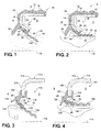
- Figure 1 illustrates a rotary shaft seal assembly, referred to hereafter as assembly, constructed in accordance with the invention generally at 10.
- the assembly 10 has an outer metal case 12, represented here, by way of example and without limitation, as being generally L-shaped, having an outer wall 14 that extends cylindrically or substantially cylindrically about a central axis 16 of the assembly 10 and a leg 18 that extends radially inwardly from the wall 14 toward the central axis 16.
- the assembly 10 further includes an elastomeric material 20, e.g.
- bond joint 24 sandwiched between the PTFE seal element 22 and the leg 18.
- the bond joint 24 is spaced radially inwardly from the leg 18 and in radial alignment with the leg 18. In use, the bond joint 24 is isolated or substantially isolated from flexing movement, thereby allowing an active sealing portion of the PTFE seal element 22 to flex as necessary to provide a reliable seal.
- the case leg 18 extends radially inwardly to a free end 26.
- the leg 18 has a first portion 28 that extends transversely or substantially transversely to the axis 16 and a second portion 30 that extends from the first portion 28 to the free end 26.
- the second portion 30 is generally frustroconical and extends from the first portion 28 radially beneath the outer wall 14 in radially spaced and radially aligned relation with at least a portion of the outer wall 14.
- the second portion 30 is formed in part by an inner surface 32 of the case 12 that is inclined to face generally toward the outer wall 14 and an outer surface 34 of the case 12 that is inclined to face generally toward the axis 16.
- the inner and outer surfaces 32, 34 extend obliquely, to the axis 16, wherein the inner surface 32 is inclined facing generally toward an oil side O of the assembly 10 and the outer surface 34 is inclined facing generally toward an air side A of the assembly 10.
- an enclosed annular pocket 36 is bounded between the outer surface 32, the first portion 28 and the outer wall 14, wherein the pocket 36 faces the oil side O of the assembly 10.
- a radially outermost portion 38 of the elastomeric material 20 can be molded about the outer surface 34 of the outer wall 14, wherein the outermost portion 38 is sized on diameter to be received in a bore of a housing (not shown), such as in a line-to-line or slight interference press fit.
- the elastomeric material 20 can be molded about the outer surface 34 of the leg first portion 28. Accordingly, the entire outer surface 34 of the leg 18 can be covered with the elastomeric material 20, thereby providing protection against to the case 12 against corrosion.
- the elastomeric material 20 can be molded to form an annular exclusion lip 39.
- the exclusion lip 39 is illustrated here, by way of example, as depending from the bond joint between the first and second portions 28, 30 of the leg 18 generally away from the PTFE seal element 22 toward the air side A of the assembly 10 to inhibit contaminants from reaching the PTFE seal element 22.
- the PTFE seal element 22 has a first bonded portion 40 and a second unsupported, non-bonded portion 42.
- the bonded portion 40 extends along the bond joint 24, which extends along the length or substantially along the length of the leg second portion 30.
- the non-bonded portion 42 extends radially inwardly generally toward the axis 16 beyond the bond joint 24 and beyond the free end 26 of the leg 18. As such, the non-bonded portion 42 forms an unsupported portion that extends in radial alignment with at least a portion of the outer wall 14.
- the unsupported portion 42 Upon being molded to the case 12, and while in an uninstalled state, the unsupported portion 42 extends radially inwardly beyond a shaft running surface, such that upon being installed about the shaft, the active sealing portion of the unsupported portion 42 is caused to sealingly engage the shaft with an amount of bias that is predetermined, based on the physical and material characteristics of the unsupported portion 42. While installed, the flexing of the PTFE seal element 22 against the shaft occurs entirely over the unsupported portion 42, and not within the bond joint 24. Accordingly, the amount of flex of the unsupported portion 42 and the magnitude of sealing force imparted by the unsupported portion 42 can be tightly controlled.
- the unsupported portion 42 can be formed having an undulating wall, such as in a coining process, for example.
- the undulating wall can be formed having a symmetrical, uniform wall thickness along its length, or it can be formed having a non-symmetrical wall thickness, thereby providing reduced thickness annular flex joints between thickened regions of the wall.
- a shaft seal assembly 110 constructed in accordance with another aspect of the invention is illustrated, wherein the same reference numerals, offset by a factor of 100, are used to indicated like features discussed above.
- the assembly 110 has a case 112 with a cylindrical outer wall 114 and a leg 118.
- the leg 118 extends transversely or substantially transversely inwardly from the outer wall 114 toward a central axis 116 to a free end 126.
- the case 112 is generally L-shaped in cross-section.
- An elastomeric material 120 is bonded to the free end 126, wherein the elastomeric material 120 forms a frustroconical annulus 46 that converges radially inwardly from an "as molded" reverse hinge region 49 toward an oil side O of the assembly 110 to provide a radially inwardly facing bonding surface 48 and a radially outwardly facing surface 50. Further, the elastomeric material 120 is formed having an exclusion lip 139 diverging toward an air side A of the assembly.
- the bonding surface 46 while in a free, unbiased and unassembled state, converges obliquely to the axis 116 and toward the oil side O of the assembly, while the surface 50 opposite the bonding surface 48 is spaced radially inwardly in radial alignment from the free end 126 of the leg 118 to provide an annular V-shaped pock 136 between the free end 126 and the surface 50.
- the seal assembly 110 has a PTFE seal element 122 with a first bonded portion 140 and a second unsupported, non-bonded portion 142, as discussed above.
- the bonded portion 140 is bonded to the bonding surface 48 of the elastomeric material 120 along a bond joint 124, wherein the bond joint 124 is spaced radially inwardly in radial alignment with the free end 126 of the leg 118.
- the non-bonded portion 142 extends radially inwardly generally toward the axis 116 beyond the bond joint 124 to form an unsupported portion 142 of the PTFE seal element 122 that extends in radial alignment with at least a portion of the outer wall 114, as discussed above.
- flexing of the PTFE seal element 122 against the shaft occurs substantially over the unsupported portion 142, and not within the bond joint 124, as discussed above, although a controlled amount of flex can occur in the hinge region 49 spaced from the bond joint 124. Accordingly, the amount of flex of the unsupported portion 142 and the magnitude of sealing force imparted by the unsupported portion 142 can be tightly controlled.
Landscapes
- Engineering & Computer Science (AREA)
- General Engineering & Computer Science (AREA)
- Mechanical Engineering (AREA)
- Sealing With Elastic Sealing Lips (AREA)
- Sealing Devices (AREA)
Applications Claiming Priority (2)
| Application Number | Priority Date | Filing Date | Title |
|---|---|---|---|
| US12/722,109 US8505926B2 (en) | 2010-03-11 | 2010-03-11 | Low torque shaft seal with improved seal element bond joint |
| PCT/US2011/021791 WO2011112280A1 (en) | 2010-03-11 | 2011-01-20 | Low torque shaft seal with improved seal element bond joint |
Publications (2)
| Publication Number | Publication Date |
|---|---|
| EP2545307A1 EP2545307A1 (en) | 2013-01-16 |
| EP2545307B1 true EP2545307B1 (en) | 2016-01-20 |
Family
ID=43736308
Family Applications (1)
| Application Number | Title | Priority Date | Filing Date |
|---|---|---|---|
| EP11702331.7A Not-in-force EP2545307B1 (en) | 2010-03-11 | 2011-01-20 | Low torque shaft seal with improved seal element bond joint |
Country Status (7)
| Country | Link |
|---|---|
| US (1) | US8505926B2 (ru) |
| EP (1) | EP2545307B1 (ru) |
| JP (1) | JP5894542B2 (ru) |
| KR (1) | KR101923426B1 (ru) |
| CN (1) | CN103109120B (ru) |
| BR (1) | BR112012022930A2 (ru) |
| WO (1) | WO2011112280A1 (ru) |
Families Citing this family (10)
| Publication number | Priority date | Publication date | Assignee | Title |
|---|---|---|---|---|
| US8313106B2 (en) * | 2010-04-06 | 2012-11-20 | Freudenberg-Nok General Partnership | Energy saving seal with main lip and dust lip hinge point |
| BR112013022021A2 (pt) | 2011-03-17 | 2016-11-29 | Federal Mogul Corp | montagem de vedação de eixo radial de baixo torque |
| DE102013108419A1 (de) * | 2013-08-05 | 2015-02-05 | Dr. Walter Hunger Beteiligungs GmbH & Co. Besitz KG | Dichtungssatz sowie Dichtungsanordnung mit zumindest einem Dichtungssatz |
| JP5988954B2 (ja) * | 2013-11-25 | 2016-09-07 | 大塚ポリテック株式会社 | パッキン及びバッテリモジュールのシール構造 |
| CN105782447B (zh) * | 2014-12-25 | 2019-06-14 | 斯凯孚公司 | 轴密封件 |
| CN109307077B (zh) * | 2017-07-27 | 2022-11-29 | 舍弗勒技术股份两合公司 | 密封组件 |
| US10527173B2 (en) | 2017-08-15 | 2020-01-07 | Aktiebolaget Skf | Resilient shaft seal |
| US20200300362A1 (en) * | 2017-11-23 | 2020-09-24 | Aktiebolaget Skf | Dirt scrapper assembly |
| KR102605672B1 (ko) * | 2018-02-23 | 2023-11-24 | 삼성전자주식회사 | 의류 건조기 |
| US20240295268A1 (en) * | 2023-03-03 | 2024-09-05 | Tenneco Inc. | Ptfe shaft seal and method of making |
Family Cites Families (33)
| Publication number | Priority date | Publication date | Assignee | Title |
|---|---|---|---|---|
| US2248761A (en) * | 1939-01-23 | 1941-07-08 | Victor Mfg & Gasket Co | Oil seal |
| US2804325A (en) * | 1954-07-16 | 1957-08-27 | Gen Motors Corp | Fluid seal |
| US3489420A (en) * | 1968-03-04 | 1970-01-13 | George V Woodling | Shaft seal assembly |
| DE2949839C2 (de) * | 1979-12-12 | 1983-05-26 | Fa. Carl Freudenberg, 6940 Weinheim | Dichtring |
| US4689190A (en) * | 1983-12-19 | 1987-08-25 | Chicago Rawhide Mfg. Co. | Method of and apparatus for molding a composite fluorocarbon helix seal |
| US4501431A (en) * | 1983-12-19 | 1985-02-26 | Chicago Rawhide Manufacturing Company | Composite teflon helix seal |
| US5244215A (en) * | 1985-05-10 | 1993-09-14 | Chicago Rawhide Manufacturing Company | Rotary shaft seal with retractable excluder lip |
| DE3524461A1 (de) * | 1985-07-09 | 1987-01-22 | Kaco Gmbh Co | Radialwellendichtring |
| DE3607662A1 (de) | 1986-03-08 | 1987-09-17 | Goetze Ag | Lippendichtungsring |
| DE3613220A1 (de) | 1986-04-18 | 1987-10-22 | Goetze Ag | Lippendichtungsring |
| US5039112A (en) * | 1988-11-25 | 1991-08-13 | John Crane Inc. | Multi-layer lip seal assembly |
| US5346662A (en) * | 1992-10-08 | 1994-09-13 | Skf Usa Inc. | Method of manufacturing a composite seal |
| JP3443423B2 (ja) * | 1993-06-04 | 2003-09-02 | Nok株式会社 | 密封装置およびその製造方法 |
| US5421741A (en) * | 1993-08-20 | 1995-06-06 | Berg Technology, Inc. | Electrical connection assembly |
| DE19501724C1 (de) * | 1995-01-20 | 1996-10-10 | Bruss Dichtungstechnik | Wellendichtring sowie Verfahren und Vorrichtung zu seiner Herstellung |
| US5577741A (en) * | 1995-07-17 | 1996-11-26 | Brenco Incorporated | Combination lip and sleeve seal and its method of manufacture |
| DE19836986C2 (de) * | 1998-08-14 | 2000-07-06 | Freudenberg Carl Fa | Radialwellendichtring |
| DE59910195D1 (de) * | 1999-02-06 | 2004-09-16 | Freudenberg Carl Kg | Dichtring |
| DE19914921C2 (de) * | 1999-04-01 | 2002-01-24 | Freudenberg Carl Fa | Dichtring |
| DE19915467A1 (de) * | 1999-04-06 | 2000-10-26 | Freudenberg Carl Fa | Radialwellendichtring |
| DE19951340C2 (de) * | 1999-10-25 | 2002-07-18 | Freudenberg Carl Kg | Dichtungsanordnung |
| US6354598B1 (en) * | 2000-02-15 | 2002-03-12 | Skf Usa Inc. | Oil seal including wear sleeve with hydrodynamic pattern |
| US6921082B2 (en) * | 2002-07-12 | 2005-07-26 | Carl Freudenberg Kg | Lip sealing ring |
| DE10117881A1 (de) * | 2001-04-10 | 2002-11-21 | Freudenberg Carl Kg | Radialwellendichtung |
| ITMI20010963A1 (it) * | 2001-05-10 | 2002-11-10 | Rft Spa | Complesso di tenuta per organi meccanici relativamente rotanti |
| DE10309907B4 (de) * | 2003-03-07 | 2007-02-01 | Carl Freudenberg Kg | Dichtring |
| CN1853063B (zh) * | 2003-09-19 | 2010-06-23 | Nok株式会社 | 密封装置 |
| US7100924B2 (en) * | 2004-01-15 | 2006-09-05 | Federal-Mogul Worldwide, Inc. | Elastomeric hinged seal |
| DE102004027539B4 (de) * | 2004-06-04 | 2020-08-27 | Ab Skf | Dichtungsanordnung |
| US20060091614A1 (en) * | 2004-11-03 | 2006-05-04 | Oricchio Lourenco A Jr | Reduction in the generation of heat under PTFE sealing element |
| US7464942B2 (en) * | 2005-06-15 | 2008-12-16 | Federal-Mogulk World Wide, Inc. | Shaft seal having independent sealing lips |
| WO2009152389A2 (en) | 2008-06-11 | 2009-12-17 | Katzenelson Omer Y | Systems and methods to perform inhibition diagnostic testing |
| US7959840B2 (en) * | 2008-06-13 | 2011-06-14 | Federal Mogul Corporation | Method of constructing a low torque shaft seal |
-
2010
- 2010-03-11 US US12/722,109 patent/US8505926B2/en not_active Expired - Fee Related
-
2011
- 2011-01-20 KR KR1020127026528A patent/KR101923426B1/ko active IP Right Grant
- 2011-01-20 WO PCT/US2011/021791 patent/WO2011112280A1/en active Application Filing
- 2011-01-20 JP JP2012557047A patent/JP5894542B2/ja not_active Expired - Fee Related
- 2011-01-20 BR BR112012022930A patent/BR112012022930A2/pt not_active IP Right Cessation
- 2011-01-20 CN CN201180020286.4A patent/CN103109120B/zh not_active Expired - Fee Related
- 2011-01-20 EP EP11702331.7A patent/EP2545307B1/en not_active Not-in-force
Also Published As
| Publication number | Publication date |
|---|---|
| JP2013522551A (ja) | 2013-06-13 |
| KR101923426B1 (ko) | 2018-11-29 |
| US8505926B2 (en) | 2013-08-13 |
| WO2011112280A1 (en) | 2011-09-15 |
| EP2545307A1 (en) | 2013-01-16 |
| BR112012022930A2 (pt) | 2016-08-02 |
| JP5894542B2 (ja) | 2016-03-30 |
| US20110221143A1 (en) | 2011-09-15 |
| CN103109120B (zh) | 2015-05-13 |
| KR20130038240A (ko) | 2013-04-17 |
| CN103109120A (zh) | 2013-05-15 |
Similar Documents
| Publication | Publication Date | Title |
|---|---|---|
| EP2545307B1 (en) | Low torque shaft seal with improved seal element bond joint | |
| CA2656664C (en) | Bearing assembly and resilient seal element | |
| US8313106B2 (en) | Energy saving seal with main lip and dust lip hinge point | |
| JP5216084B2 (ja) | リップタイプシール | |
| US6213476B1 (en) | Bi-modulus composite seal and its method of manufacture | |
| US20020149154A1 (en) | Retrofittable severe duty seal for a shaft | |
| US9394998B2 (en) | Radial shaft seal assembly with snap in auxiliary member | |
| EP1891358A2 (en) | Shaft seal having independent sealing lips | |
| US9869393B2 (en) | Shaft seal, especially radial shaft seal | |
| EP2748494B1 (en) | Radial shaft seal with dust exclusion and hydrodynamic sealing feature | |
| US20050173869A1 (en) | Spark plug tube seal | |
| WO2016076247A1 (ja) | 密封装置 | |
| US7100924B2 (en) | Elastomeric hinged seal | |
| EP2949972B1 (en) | Cassette seal | |
| US20060186603A1 (en) | Dynamic seal | |
| US20170045140A1 (en) | Dynamic seal | |
| JP2007247708A (ja) | 軸付きシール | |
| WO1990011463A1 (en) | Low friction radial lip seal | |
| US20090289424A1 (en) | Ball Joint Dust Seal With Lubricating Flutes | |
| JP3138507U (ja) | 密封装置 | |
| CN104870840A (zh) | 球窝接头用防尘罩 | |
| JP7224248B2 (ja) | 密封装置 | |
| US20190107204A1 (en) | Seal Assembly with Eccentricity Tracking | |
| CN113565961A (zh) | 密封装置 | |
| JP2005265079A (ja) | 密封装置 |
Legal Events
| Date | Code | Title | Description |
|---|---|---|---|
| PUAI | Public reference made under article 153(3) epc to a published international application that has entered the european phase |
Free format text: ORIGINAL CODE: 0009012 |
|
| 17P | Request for examination filed |
Effective date: 20120917 |
|
| AK | Designated contracting states |
Kind code of ref document: A1 Designated state(s): AL AT BE BG CH CY CZ DE DK EE ES FI FR GB GR HR HU IE IS IT LI LT LU LV MC MK MT NL NO PL PT RO RS SE SI SK SM TR |
|
| DAX | Request for extension of the european patent (deleted) | ||
| GRAP | Despatch of communication of intention to grant a patent |
Free format text: ORIGINAL CODE: EPIDOSNIGR1 |
|
| INTG | Intention to grant announced |
Effective date: 20151001 |
|
| GRAS | Grant fee paid |
Free format text: ORIGINAL CODE: EPIDOSNIGR3 |
|
| GRAA | (expected) grant |
Free format text: ORIGINAL CODE: 0009210 |
|
| AK | Designated contracting states |
Kind code of ref document: B1 Designated state(s): AL AT BE BG CH CY CZ DE DK EE ES FI FR GB GR HR HU IE IS IT LI LT LU LV MC MK MT NL NO PL PT RO RS SE SI SK SM TR |
|
| REG | Reference to a national code |
Ref country code: GB Ref legal event code: FG4D |
|
| REG | Reference to a national code |
Ref country code: CH Ref legal event code: EP |
|
| REG | Reference to a national code |
Ref country code: IE Ref legal event code: FG4D |
|
| REG | Reference to a national code |
Ref country code: AT Ref legal event code: REF Ref document number: 771889 Country of ref document: AT Kind code of ref document: T Effective date: 20160215 |
|
| REG | Reference to a national code |
Ref country code: DE Ref legal event code: R096 Ref document number: 602011022790 Country of ref document: DE Ref country code: FR Ref legal event code: PLFP Year of fee payment: 6 |
|
| REG | Reference to a national code |
Ref country code: LT Ref legal event code: MG4D Ref country code: NL Ref legal event code: MP Effective date: 20160120 |
|
| PG25 | Lapsed in a contracting state [announced via postgrant information from national office to epo] |
Ref country code: BE Free format text: LAPSE BECAUSE OF NON-PAYMENT OF DUE FEES Effective date: 20160131 |
|
| REG | Reference to a national code |
Ref country code: AT Ref legal event code: MK05 Ref document number: 771889 Country of ref document: AT Kind code of ref document: T Effective date: 20160120 |
|
| PG25 | Lapsed in a contracting state [announced via postgrant information from national office to epo] |
Ref country code: NL Free format text: LAPSE BECAUSE OF FAILURE TO SUBMIT A TRANSLATION OF THE DESCRIPTION OR TO PAY THE FEE WITHIN THE PRESCRIBED TIME-LIMIT Effective date: 20160120 |
|
| PG25 | Lapsed in a contracting state [announced via postgrant information from national office to epo] |
Ref country code: GR Free format text: LAPSE BECAUSE OF FAILURE TO SUBMIT A TRANSLATION OF THE DESCRIPTION OR TO PAY THE FEE WITHIN THE PRESCRIBED TIME-LIMIT Effective date: 20160421 Ref country code: NO Free format text: LAPSE BECAUSE OF FAILURE TO SUBMIT A TRANSLATION OF THE DESCRIPTION OR TO PAY THE FEE WITHIN THE PRESCRIBED TIME-LIMIT Effective date: 20160420 Ref country code: FI Free format text: LAPSE BECAUSE OF FAILURE TO SUBMIT A TRANSLATION OF THE DESCRIPTION OR TO PAY THE FEE WITHIN THE PRESCRIBED TIME-LIMIT Effective date: 20160120 Ref country code: HR Free format text: LAPSE BECAUSE OF FAILURE TO SUBMIT A TRANSLATION OF THE DESCRIPTION OR TO PAY THE FEE WITHIN THE PRESCRIBED TIME-LIMIT Effective date: 20160120 Ref country code: ES Free format text: LAPSE BECAUSE OF FAILURE TO SUBMIT A TRANSLATION OF THE DESCRIPTION OR TO PAY THE FEE WITHIN THE PRESCRIBED TIME-LIMIT Effective date: 20160120 |
|
| PG25 | Lapsed in a contracting state [announced via postgrant information from national office to epo] |
Ref country code: LT Free format text: LAPSE BECAUSE OF FAILURE TO SUBMIT A TRANSLATION OF THE DESCRIPTION OR TO PAY THE FEE WITHIN THE PRESCRIBED TIME-LIMIT Effective date: 20160120 Ref country code: PT Free format text: LAPSE BECAUSE OF FAILURE TO SUBMIT A TRANSLATION OF THE DESCRIPTION OR TO PAY THE FEE WITHIN THE PRESCRIBED TIME-LIMIT Effective date: 20160520 Ref country code: RS Free format text: LAPSE BECAUSE OF FAILURE TO SUBMIT A TRANSLATION OF THE DESCRIPTION OR TO PAY THE FEE WITHIN THE PRESCRIBED TIME-LIMIT Effective date: 20160120 Ref country code: IS Free format text: LAPSE BECAUSE OF FAILURE TO SUBMIT A TRANSLATION OF THE DESCRIPTION OR TO PAY THE FEE WITHIN THE PRESCRIBED TIME-LIMIT Effective date: 20160520 Ref country code: LV Free format text: LAPSE BECAUSE OF FAILURE TO SUBMIT A TRANSLATION OF THE DESCRIPTION OR TO PAY THE FEE WITHIN THE PRESCRIBED TIME-LIMIT Effective date: 20160120 Ref country code: SE Free format text: LAPSE BECAUSE OF FAILURE TO SUBMIT A TRANSLATION OF THE DESCRIPTION OR TO PAY THE FEE WITHIN THE PRESCRIBED TIME-LIMIT Effective date: 20160120 Ref country code: AT Free format text: LAPSE BECAUSE OF FAILURE TO SUBMIT A TRANSLATION OF THE DESCRIPTION OR TO PAY THE FEE WITHIN THE PRESCRIBED TIME-LIMIT Effective date: 20160120 Ref country code: PL Free format text: LAPSE BECAUSE OF FAILURE TO SUBMIT A TRANSLATION OF THE DESCRIPTION OR TO PAY THE FEE WITHIN THE PRESCRIBED TIME-LIMIT Effective date: 20160120 |
|
| PGFP | Annual fee paid to national office [announced via postgrant information from national office to epo] |
Ref country code: IT Payment date: 20160329 Year of fee payment: 6 |
|
| REG | Reference to a national code |
Ref country code: CH Ref legal event code: PL |
|
| REG | Reference to a national code |
Ref country code: DE Ref legal event code: R097 Ref document number: 602011022790 Country of ref document: DE |
|
| PG25 | Lapsed in a contracting state [announced via postgrant information from national office to epo] |
Ref country code: LI Free format text: LAPSE BECAUSE OF NON-PAYMENT OF DUE FEES Effective date: 20160131 Ref country code: DK Free format text: LAPSE BECAUSE OF FAILURE TO SUBMIT A TRANSLATION OF THE DESCRIPTION OR TO PAY THE FEE WITHIN THE PRESCRIBED TIME-LIMIT Effective date: 20160120 Ref country code: CH Free format text: LAPSE BECAUSE OF NON-PAYMENT OF DUE FEES Effective date: 20160131 Ref country code: EE Free format text: LAPSE BECAUSE OF FAILURE TO SUBMIT A TRANSLATION OF THE DESCRIPTION OR TO PAY THE FEE WITHIN THE PRESCRIBED TIME-LIMIT Effective date: 20160120 |
|
| REG | Reference to a national code |
Ref country code: IE Ref legal event code: MM4A |
|
| PLBE | No opposition filed within time limit |
Free format text: ORIGINAL CODE: 0009261 |
|
| STAA | Information on the status of an ep patent application or granted ep patent |
Free format text: STATUS: NO OPPOSITION FILED WITHIN TIME LIMIT |
|
| PG25 | Lapsed in a contracting state [announced via postgrant information from national office to epo] |
Ref country code: RO Free format text: LAPSE BECAUSE OF FAILURE TO SUBMIT A TRANSLATION OF THE DESCRIPTION OR TO PAY THE FEE WITHIN THE PRESCRIBED TIME-LIMIT Effective date: 20160120 Ref country code: SK Free format text: LAPSE BECAUSE OF FAILURE TO SUBMIT A TRANSLATION OF THE DESCRIPTION OR TO PAY THE FEE WITHIN THE PRESCRIBED TIME-LIMIT Effective date: 20160120 Ref country code: SM Free format text: LAPSE BECAUSE OF FAILURE TO SUBMIT A TRANSLATION OF THE DESCRIPTION OR TO PAY THE FEE WITHIN THE PRESCRIBED TIME-LIMIT Effective date: 20160120 Ref country code: CZ Free format text: LAPSE BECAUSE OF FAILURE TO SUBMIT A TRANSLATION OF THE DESCRIPTION OR TO PAY THE FEE WITHIN THE PRESCRIBED TIME-LIMIT Effective date: 20160120 |
|
| 26N | No opposition filed |
Effective date: 20161021 |
|
| GBPC | Gb: european patent ceased through non-payment of renewal fee |
Effective date: 20160420 |
|
| PG25 | Lapsed in a contracting state [announced via postgrant information from national office to epo] |
Ref country code: BE Free format text: LAPSE BECAUSE OF FAILURE TO SUBMIT A TRANSLATION OF THE DESCRIPTION OR TO PAY THE FEE WITHIN THE PRESCRIBED TIME-LIMIT Effective date: 20160120 |
|
| REG | Reference to a national code |
Ref country code: FR Ref legal event code: PLFP Year of fee payment: 7 |
|
| PG25 | Lapsed in a contracting state [announced via postgrant information from national office to epo] |
Ref country code: IE Free format text: LAPSE BECAUSE OF NON-PAYMENT OF DUE FEES Effective date: 20160120 Ref country code: GB Free format text: LAPSE BECAUSE OF NON-PAYMENT OF DUE FEES Effective date: 20160420 |
|
| PG25 | Lapsed in a contracting state [announced via postgrant information from national office to epo] |
Ref country code: BG Free format text: LAPSE BECAUSE OF FAILURE TO SUBMIT A TRANSLATION OF THE DESCRIPTION OR TO PAY THE FEE WITHIN THE PRESCRIBED TIME-LIMIT Effective date: 20160420 Ref country code: SI Free format text: LAPSE BECAUSE OF FAILURE TO SUBMIT A TRANSLATION OF THE DESCRIPTION OR TO PAY THE FEE WITHIN THE PRESCRIBED TIME-LIMIT Effective date: 20160120 |
|
| PG25 | Lapsed in a contracting state [announced via postgrant information from national office to epo] |
Ref country code: MT Free format text: LAPSE BECAUSE OF FAILURE TO SUBMIT A TRANSLATION OF THE DESCRIPTION OR TO PAY THE FEE WITHIN THE PRESCRIBED TIME-LIMIT Effective date: 20160120 |
|
| PG25 | Lapsed in a contracting state [announced via postgrant information from national office to epo] |
Ref country code: MC Free format text: LAPSE BECAUSE OF FAILURE TO SUBMIT A TRANSLATION OF THE DESCRIPTION OR TO PAY THE FEE WITHIN THE PRESCRIBED TIME-LIMIT Effective date: 20160120 |
|
| REG | Reference to a national code |
Ref country code: FR Ref legal event code: PLFP Year of fee payment: 8 |
|
| PGFP | Annual fee paid to national office [announced via postgrant information from national office to epo] |
Ref country code: FR Payment date: 20171220 Year of fee payment: 8 |
|
| PG25 | Lapsed in a contracting state [announced via postgrant information from national office to epo] |
Ref country code: IT Free format text: LAPSE BECAUSE OF NON-PAYMENT OF DUE FEES Effective date: 20170120 |
|
| PG25 | Lapsed in a contracting state [announced via postgrant information from national office to epo] |
Ref country code: HU Free format text: LAPSE BECAUSE OF FAILURE TO SUBMIT A TRANSLATION OF THE DESCRIPTION OR TO PAY THE FEE WITHIN THE PRESCRIBED TIME-LIMIT; INVALID AB INITIO Effective date: 20110120 Ref country code: CY Free format text: LAPSE BECAUSE OF FAILURE TO SUBMIT A TRANSLATION OF THE DESCRIPTION OR TO PAY THE FEE WITHIN THE PRESCRIBED TIME-LIMIT Effective date: 20160120 |
|
| PG25 | Lapsed in a contracting state [announced via postgrant information from national office to epo] |
Ref country code: LU Free format text: LAPSE BECAUSE OF NON-PAYMENT OF DUE FEES Effective date: 20160120 Ref country code: MK Free format text: LAPSE BECAUSE OF FAILURE TO SUBMIT A TRANSLATION OF THE DESCRIPTION OR TO PAY THE FEE WITHIN THE PRESCRIBED TIME-LIMIT Effective date: 20160120 Ref country code: TR Free format text: LAPSE BECAUSE OF FAILURE TO SUBMIT A TRANSLATION OF THE DESCRIPTION OR TO PAY THE FEE WITHIN THE PRESCRIBED TIME-LIMIT Effective date: 20160120 Ref country code: MT Free format text: LAPSE BECAUSE OF FAILURE TO SUBMIT A TRANSLATION OF THE DESCRIPTION OR TO PAY THE FEE WITHIN THE PRESCRIBED TIME-LIMIT Effective date: 20160131 |
|
| REG | Reference to a national code |
Ref country code: DE Ref legal event code: R082 Ref document number: 602011022790 Country of ref document: DE Representative=s name: BECKER-KURIG-STRAUS PATENTANWAELTE PARTNERSCHA, DE Ref country code: DE Ref legal event code: R082 Ref document number: 602011022790 Country of ref document: DE Representative=s name: BECKER & KURIG PARTNERSCHAFT PATENTANWAELTE MB, DE Ref country code: DE Ref legal event code: R082 Ref document number: 602011022790 Country of ref document: DE Representative=s name: BECKER & KURIG PARTNERSCHAFT PATENTANWAELTE PA, DE Ref country code: DE Ref legal event code: R082 Ref document number: 602011022790 Country of ref document: DE Representative=s name: BECKER, KURIG, STRAUS, DE Ref country code: DE Ref legal event code: R081 Ref document number: 602011022790 Country of ref document: DE Owner name: FEDERAL-MOGUL LLC (N. D. GES. D. STAATES DELAW, US Free format text: FORMER OWNER: FEDERAL-MOGUL CORPORATION, SOUTHFIELD, MICH., US |
|
| PG25 | Lapsed in a contracting state [announced via postgrant information from national office to epo] |
Ref country code: AL Free format text: LAPSE BECAUSE OF FAILURE TO SUBMIT A TRANSLATION OF THE DESCRIPTION OR TO PAY THE FEE WITHIN THE PRESCRIBED TIME-LIMIT Effective date: 20160120 |
|
| PGFP | Annual fee paid to national office [announced via postgrant information from national office to epo] |
Ref country code: DE Payment date: 20181219 Year of fee payment: 9 |
|
| PG25 | Lapsed in a contracting state [announced via postgrant information from national office to epo] |
Ref country code: FR Free format text: LAPSE BECAUSE OF NON-PAYMENT OF DUE FEES Effective date: 20190131 |
|
| REG | Reference to a national code |
Ref country code: DE Ref legal event code: R119 Ref document number: 602011022790 Country of ref document: DE |
|
| PG25 | Lapsed in a contracting state [announced via postgrant information from national office to epo] |
Ref country code: DE Free format text: LAPSE BECAUSE OF NON-PAYMENT OF DUE FEES Effective date: 20200801 |