EP2545207B1 - Dispositif d'electrolyse de l'eau a haute temperature a fonctionnement ameliore - Google Patents
Dispositif d'electrolyse de l'eau a haute temperature a fonctionnement ameliore Download PDFInfo
- Publication number
- EP2545207B1 EP2545207B1 EP11707435.1A EP11707435A EP2545207B1 EP 2545207 B1 EP2545207 B1 EP 2545207B1 EP 11707435 A EP11707435 A EP 11707435A EP 2545207 B1 EP2545207 B1 EP 2545207B1
- Authority
- EP
- European Patent Office
- Prior art keywords
- plane
- electrolysis
- chamber
- holes
- anode
- Prior art date
- Legal status (The legal status is an assumption and is not a legal conclusion. Google has not performed a legal analysis and makes no representation as to the accuracy of the status listed.)
- Not-in-force
Links
- 238000005868 electrolysis reaction Methods 0.000 title claims description 55
- XLYOFNOQVPJJNP-UHFFFAOYSA-N water Substances O XLYOFNOQVPJJNP-UHFFFAOYSA-N 0.000 title claims description 44
- 229910052739 hydrogen Inorganic materials 0.000 claims description 25
- UFHFLCQGNIYNRP-UHFFFAOYSA-N Hydrogen Chemical compound [H][H] UFHFLCQGNIYNRP-UHFFFAOYSA-N 0.000 claims description 22
- 239000001257 hydrogen Substances 0.000 claims description 22
- 239000002184 metal Substances 0.000 claims description 11
- 239000003792 electrolyte Substances 0.000 claims description 10
- 239000012530 fluid Substances 0.000 claims description 7
- 238000004519 manufacturing process Methods 0.000 claims description 5
- 239000004020 conductor Substances 0.000 claims description 2
- 210000004027 cell Anatomy 0.000 description 40
- QVGXLLKOCUKJST-UHFFFAOYSA-N atomic oxygen Chemical compound [O] QVGXLLKOCUKJST-UHFFFAOYSA-N 0.000 description 14
- 229910052760 oxygen Inorganic materials 0.000 description 14
- 239000001301 oxygen Substances 0.000 description 14
- 239000007789 gas Substances 0.000 description 13
- 229920000297 Rayon Polymers 0.000 description 5
- 239000002964 rayon Substances 0.000 description 5
- 230000007423 decrease Effects 0.000 description 4
- 239000000463 material Substances 0.000 description 4
- 230000035699 permeability Effects 0.000 description 3
- 238000005452 bending Methods 0.000 description 2
- 230000003750 conditioning effect Effects 0.000 description 2
- 238000002347 injection Methods 0.000 description 2
- 239000007924 injection Substances 0.000 description 2
- 239000000203 mixture Substances 0.000 description 2
- 238000011144 upstream manufacturing Methods 0.000 description 2
- 230000015556 catabolic process Effects 0.000 description 1
- 238000006243 chemical reaction Methods 0.000 description 1
- 230000007547 defect Effects 0.000 description 1
- 238000006731 degradation reaction Methods 0.000 description 1
- 238000007599 discharging Methods 0.000 description 1
- 230000000694 effects Effects 0.000 description 1
- 238000003487 electrochemical reaction Methods 0.000 description 1
- 230000005518 electrochemistry Effects 0.000 description 1
- 239000011532 electronic conductor Substances 0.000 description 1
- 238000005265 energy consumption Methods 0.000 description 1
- 239000002737 fuel gas Substances 0.000 description 1
- 239000012212 insulator Substances 0.000 description 1
- 239000010416 ion conductor Substances 0.000 description 1
- 150000002500 ions Chemical class 0.000 description 1
- 238000003754 machining Methods 0.000 description 1
- 239000011148 porous material Substances 0.000 description 1
- 230000000135 prohibitive effect Effects 0.000 description 1
- 238000011084 recovery Methods 0.000 description 1
- 230000009467 reduction Effects 0.000 description 1
- 238000007493 shaping process Methods 0.000 description 1
- 239000007787 solid Substances 0.000 description 1
- 239000000243 solution Substances 0.000 description 1
Images


Classifications
-
- C—CHEMISTRY; METALLURGY
- C25—ELECTROLYTIC OR ELECTROPHORETIC PROCESSES; APPARATUS THEREFOR
- C25B—ELECTROLYTIC OR ELECTROPHORETIC PROCESSES FOR THE PRODUCTION OF COMPOUNDS OR NON-METALS; APPARATUS THEREFOR
- C25B1/00—Electrolytic production of inorganic compounds or non-metals
- C25B1/01—Products
- C25B1/02—Hydrogen or oxygen
- C25B1/04—Hydrogen or oxygen by electrolysis of water
-
- C—CHEMISTRY; METALLURGY
- C02—TREATMENT OF WATER, WASTE WATER, SEWAGE, OR SLUDGE
- C02F—TREATMENT OF WATER, WASTE WATER, SEWAGE, OR SLUDGE
- C02F1/00—Treatment of water, waste water, or sewage
- C02F1/46—Treatment of water, waste water, or sewage by electrochemical methods
- C02F1/461—Treatment of water, waste water, or sewage by electrochemical methods by electrolysis
-
- C—CHEMISTRY; METALLURGY
- C25—ELECTROLYTIC OR ELECTROPHORETIC PROCESSES; APPARATUS THEREFOR
- C25B—ELECTROLYTIC OR ELECTROPHORETIC PROCESSES FOR THE PRODUCTION OF COMPOUNDS OR NON-METALS; APPARATUS THEREFOR
- C25B9/00—Cells or assemblies of cells; Constructional parts of cells; Assemblies of constructional parts, e.g. electrode-diaphragm assemblies; Process-related cell features
- C25B9/17—Cells comprising dimensionally-stable non-movable electrodes; Assemblies of constructional parts thereof
- C25B9/19—Cells comprising dimensionally-stable non-movable electrodes; Assemblies of constructional parts thereof with diaphragms
-
- C—CHEMISTRY; METALLURGY
- C25—ELECTROLYTIC OR ELECTROPHORETIC PROCESSES; APPARATUS THEREFOR
- C25B—ELECTROLYTIC OR ELECTROPHORETIC PROCESSES FOR THE PRODUCTION OF COMPOUNDS OR NON-METALS; APPARATUS THEREFOR
- C25B9/00—Cells or assemblies of cells; Constructional parts of cells; Assemblies of constructional parts, e.g. electrode-diaphragm assemblies; Process-related cell features
- C25B9/60—Constructional parts of cells
- C25B9/65—Means for supplying current; Electrode connections; Electric inter-cell connections
-
- C—CHEMISTRY; METALLURGY
- C25—ELECTROLYTIC OR ELECTROPHORETIC PROCESSES; APPARATUS THEREFOR
- C25B—ELECTROLYTIC OR ELECTROPHORETIC PROCESSES FOR THE PRODUCTION OF COMPOUNDS OR NON-METALS; APPARATUS THEREFOR
- C25B9/00—Cells or assemblies of cells; Constructional parts of cells; Assemblies of constructional parts, e.g. electrode-diaphragm assemblies; Process-related cell features
- C25B9/70—Assemblies comprising two or more cells
-
- Y—GENERAL TAGGING OF NEW TECHNOLOGICAL DEVELOPMENTS; GENERAL TAGGING OF CROSS-SECTIONAL TECHNOLOGIES SPANNING OVER SEVERAL SECTIONS OF THE IPC; TECHNICAL SUBJECTS COVERED BY FORMER USPC CROSS-REFERENCE ART COLLECTIONS [XRACs] AND DIGESTS
- Y02—TECHNOLOGIES OR APPLICATIONS FOR MITIGATION OR ADAPTATION AGAINST CLIMATE CHANGE
- Y02E—REDUCTION OF GREENHOUSE GAS [GHG] EMISSIONS, RELATED TO ENERGY GENERATION, TRANSMISSION OR DISTRIBUTION
- Y02E60/00—Enabling technologies; Technologies with a potential or indirect contribution to GHG emissions mitigation
- Y02E60/30—Hydrogen technology
- Y02E60/36—Hydrogen production from non-carbon containing sources, e.g. by water electrolysis
Definitions
- the invention relates to a high temperature water electrolysis device also called high temperature water electrolyser (EHT) also called high temperature steam electrolyser (EVHT).
- EHT high temperature water electrolyser
- EVHT high temperature steam electrolyser
- a high temperature water electrolyser comprises at least one elementary electrochemical cell formed of an electrolyte, a cathode and an anode, the electrolyte being interposed between the anode and the cathode.
- the electrolyte is gastight, electronic insulator and ionic conductor.
- the electrodes (anode and cathode) are made of porous material and electronic conductors.
- An EHT electrolyser also includes fluidic and electrical interconnection devices that are in electrical contact with one or more electrodes. These interconnection devices, generally provide the functions of supply and collection of current and which delimit one or more compartments of gas circulation.
- a so-called cathodic compartment has the function of distributing the current and water vapor as well as recovering the hydrogen at the cathode in contact.
- a so-called anode compartment has the function of distributing the current as well as recovering the oxygen produced at the anode in contact.
- a draining gas may also be injected at the inlet of the anode compartment to evacuate the oxygen produced.
- the injection of a draining gas has the additional function of acting as a thermal regulator.
- FR 2921390 discloses a high temperature water electrolysis device comprising an interconnecting plate with channels.
- FIGs 1, 1A and 1B a channel plate 1 commonly used as an interconnect device.
- the supply or collection of current to the electrode is performed by the teeth or ribs 10 which are in direct mechanical contact with the electrode concerned.
- the supply of water vapor to the cathode (or draining gas at the anode) is symbolized by the arrows in figure 1 .
- the collection of the hydrogen produced at the cathode (or oxygen produced at the anode) is made by the channels 11 which open into a fluid connection, commonly called clarinet, common to the stack of cells.
- clarinet a fluid connection
- the electrochemical reaction being close to the interface between electrode and electrolyte, and requiring the presence on the same place of the gas, electrons and ions involved, the areas under the teeth 10 of the collector are easy to supply electrons but difficult to fuel gas.
- the binding parameters are the permeability of the electrode in contact, its thickness and the width of the tooth 10.
- the zone under the channel 11 is difficult to supply with electrons, the existing electrodes to date having a low effective conductivity .
- the binding parameters are the effective conductivity, the thickness and the width of the channel 11.
- the ratio R between the supply / current collection surface and the water vapor feed surface or collection of gases produced is a parameter indicator of the actual use of the cell surface.
- the ratio R calculated as below is often less than 50%.
- R 1 / (1+ w / L), where w is the width of the channel 11 and L the width of the tooth 10.
- this plate structure 1 involves differentiated production zones with certain zones in which the production densities and therefore the current densities can be very high, this for a low average density, and therefore localized performance degradation sources. This is illustrated at the local level (millimeter scale) in Figure 1B on which we can see the very strong current lines represented which are located at the ribs 10. Similarly, considering the electrode surface, the current lines are stronger upstream than downstream due to the evolution of the content of the water in the gas flow between upstream and downstream channels.
- this plate structure 1 implies inhomogeneities for supplying water vapor to the channels 11 and forces a strong super-feed of this water vapor (between a surplus of water corresponding to more than 100% of the water). water consumed) to obtain a supply for all the channels 11 stable and homogeneous, which makes it difficult to achieve a high rate of use of water vapor.
- the conditioning of this steam and its pressurization have a significant impact on the energy consumption associated with the electrolyser.
- the channel structure with an inlet and an outlet has reason to be that when a draining gas is used to evacuate the oxygen produced to the outlet.
- the conditioning this draining gas also has a significant energy cost.
- this plate structure requires a material thickness that is important for the collection zone of the gases produced and a shaping (machining) that can be prohibitive.
- the use of thin sheets and stamping are used but limit the possibilities of realization for the unit width of tooth and the pitch between teeth. Also, the inventor considers that with such an interconnecting plate with channels 1, the reduction in the inhomogeneity of the currents brought to each cell can only be limited.
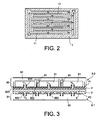
- Another interconnecting plate 1 has already been proposed [1]. She is represented in figure 2 with the circulation of the fluid represented by the arrows: its structure is of interdigitated type. It does not solve the problem of the mechanical bending mentioned for the plate 1 and can cause a hydraulic tearing of the electrode with which it is in contact.
- the object of the invention is to propose a solution that makes it possible to overcome all or part of the disadvantages of the existing interconnect plates at the cathode of a device for electrolysis of water at high temperature.
- Part of the cathode compartment according to the invention by which the steam is brought is thus constituted of one of the two chambers and a group of holes.
- the other group of holes and the other of the two chambers according to the invention constitute another part of the cathode compartment by which the hydrogen produced at the cathode is recovered.
- an electrolysis device may comprise a single electrolysis cell with a first interconnector in contact with its cathode and a second interconnector described below in contact with its anode.
- an interconnecting plate may comprise a first interconnector in contact with the cathode of an elementary electrolysis cell and a second interconnector in contact with the anode of the adjacent electrolysis cell.
- the current distribution at the cathode is optimal.
- the water vapor can be injected directly homogeneously at any point of the cathode through a group of holes, which which has the effect, contrary to the state of the art, a limitation of the concentration overvoltage.
- the adjacent chamber constitutes the chamber through which the water vapor is fed and the furthest chamber constitutes the collection chamber for the hydrogen produced by the electrolysis.
- the adjacent chamber is the collection chamber of the hydrogen produced by the electrolysis and the furthest chamber is the chamber through which water vapor is supplied.
- the holes are of circular section with a diameter of between 0.5 and 5 mm, preferably between 1.25 mm and 2.5 mm.
- the distance between the center of two adjacent holes is between 7 mm and 28 mm, preferably between 7 mm and 14 mm. With such distances, it is possible to obtain head losses of less than 200 millibars, according to electrolysis cells conforming to those used in the calculations with reference to the examples below.
- the holes are preferably aligned along lines parallel to each other and regularly spaced.
- the alternation can be furthermore made in such a way that the holes of the group emerging at the same time on the plane P1 and directly in the adjacent chamber are staggered with the holes of the group emerging at the same time on the plane P1 and in the chamber the farthest, each hole of the group opening on both the plane P1 and directly in the adjacent chamber being in the middle of four holes of the group opening on both the plane P1 and in the furthest chamber and vice versa.
- the four holes of one group form a square, the hole of the other group being in the middle of the square.
- the staggered alternation principle induces an even more homogeneous operation over the whole cell both from the point of view of the fluidics (supply of the water vapor and collection of the produced hydrogen), than of the thermal (distributed heat at any point in the electrolysis cell uniformly) or electrochemistry (identical electrolysis reaction at any point in the cell).
- the first interconnector is thus dimensionally simple to achieve.
- the electrolysis device of the invention may comprise a second device forming an electrical and fluidic interconnector consisting of a metal part delimited by at least one plane, said metal part comprising internally a chamber and a plurality of holes distributed over the surface, substantially perpendicular to the plane and opening at the same time on the latter and in the room, the plane of the second interconnector being in mechanical contact with the plane of the anode.
- the plane P2 of the second interconnector may be in direct mechanical contact with the plane of the anode.
- the electrolysis device of the water according to the invention may comprise a stack of elementary electrolysis cells each formed of a cathode, an anode and an electrolyte interposed between the cathode and the anode, a plate interconnector comprising a first and a second interconnector being arranged between two adjacent elementary cells, such that the plane P1 of the first interconnector is in mechanical contact with the cathode of one of the two elementary cells and the plane of the second interconnector is in mechanical contact with the anode of the other of the two elementary cells.
- the invention finally relates to a hydrogen production assembly comprising a plurality of electrolysis devices as described above.
- the high temperature electrolysis according to the invention can be carried out at temperatures of at least 450 ° C., typically between 700 ° C. and 1000 ° C.
- an electrolysis device comprises an elementary electrolysis cell formed of a cathode 2, an anode 4, and an electrolyte 6 interposed between the cathode and the anode.
- a first device 8.0 forming an electrical and fluidic interconnector consisting of a metal part 80 delimited by at least one plane P1.
- the metal part 80 internally comprises two chambers 81, 82 superimposed on one another and a plurality of holes 810, 820 substantially perpendicular to the plane P1 and divided into two groups.
- One of the groups of holes 810 opens on both the plane P1 and directly into the adjacent chamber 81 and the other group of the holes 820 opens on both the plane P1 and in the chamber 82 the farthest via channels 83.
- the plane P1 of the first interconnector 8.0 is in mechanical contact with the plane of the cathode 2.
- the water vapor injected by this chamber 82 then flows through the channels 83, then is progressively transformed into hydrogen in the porosity of the cathode 2 and thanks to the uniform supply of electric current over the entire cell surface by the Interconnect 8.0.
- One part of hydrogen is sampled uniformly by each of the holes 810 of the other group and then discharged through the chamber 81 on which the holes 810 open.
- the electrolysis device according to the invention as represented in figure 3 comprises, on the anode side 4, a second interconnector 8.1.
- This interconnector 8.1 also consists of a metal part 84 delimited by a plane P2 in direct mechanical contact with the plane of the anode 4.
- the metal part 84 internally comprises a chamber 85 and a plurality of holes 850 distributed on the surface, substantially perpendicular to the plane and opening on both this plane P2 and in the chamber 85.
- the oxygen produced at the anode 4 is collected by each of the holes 850 and is evacuated by the chamber 85.
- the metal part 80 is constituted by the assembly of three plates between them 80A, 80B, 80C parallel to each other.
- One of the plates 80A is pierced with two groups of holes 810, 820 arranged in lines parallel to each other and regularly spaced.
- the second plate 80B is also pierced but of a single group 800B of holes which communicates with the group of holes 820 of the first plate 80A by through tubular struts which constitute the channels 83.
- the space between the first plate 80A and the second plate 80b constitutes the chamber 81 for collecting hydrogen.
- the third plate 80C is solid and separated from a space with the second plate 80B which constitutes the other chamber 81 for supplying water vapor.
- the holes 810 are staggered with the holes 820, four holes 810 forming a square, with a hole 820 in the middle of the square.
- the current is brought and recovered at the terminals of the stack formed on the one hand by a first interconnector device 8.0 in contact with the cathode of the cell C1 and on the other hand by a second interconnector device 8.1 in contact with the cell C3.
- An interconnecting plate consisting of a second interconnector 8.1 and a first interconnector 8.0 is arranged between the cell C1 and the cell C2, the second interconnector 8.1 being in contact with the plane P2 of the anode of the cell C1 and the first interconnector 8.0 being in contact with the plane P1 of the cathode of the adjacent cell C2.
- the inventor has carried out finite element design calculations using ANSYS FLUENT software version 12.0 to validate the size, the number and the distribution of the holes according to the invention as a function of an imposed operating pressure.
- the calculations were made on a repetition pattern as presented in figure 5 , the repetition pattern being an isosceles triangle of length L defining the pitch of the pattern with a vertex coinciding with the center of a hole 820 through which water vapor arrives and another vertex coinciding with the center of a hole 810 through which the hydrogen produced is evacuated.
- Electrolysis cell Unit Value Cathode 2 Constitutive material YZS Ni- Thickness microns 315 Thermal conductivity W m -1 K -1 13.1 Electrical conductivity ⁇ -1 m -1 10 5 Porosity 0.37 Permeability m 2 10-13 crookedness 4 Current density A m -2 5300 Anode 3 Constitutive material LSM Thickness microns 20 Thermal conductivity W m -1 K -1 9.6 Electrical conductivity ⁇ -1 m -1 1 10 4 Porosity 0. 37 Permeability m 2 10-13 crookedness 3.0 4 Current density Am -2 2000 Electrolyte 4 Constitutive material YSZ Thickness microns 15 Resistivity ⁇ m 0.42
- the metal part 84 constituting the second interconnector 8.1 is in direct mechanical contact with the anode 4, as shown in FIG. figure 3 .
- the plane P2 of this second interconnector 8.1 is in direct mechanical contact with the plane of the anode as shown in FIG. figure 3 .
- the holes 850 for collecting the oxygen produced are alternately aligned in staggered rows exactly like all the holes 810, 820 for supplying steam and collecting oxygen respectively.
- Example 2 is identical to Example 1, with the exception of the pressure imposed: it is 30 bars and is the same at the outlet of chamber 81 for collecting hydrogen and at the outlet of chamber 85 for collecting oxygen.
- the calculations for this example 2 yield: L (mm) R (mm) ⁇ H 2 (mol fraction of H2) at the outlet Pressure drop ⁇ P cathode 2 (Pa) Current density (A / cm 2 ) Average Potential Nernst (V) Pressure drop ⁇ P anode 4 (Pa) 5.00 0.50 0894 6558.4 1017 0.97778 4486.2 5.00 1.00 0893 4607.2 1015 0.97775 2454.4 5.00 1.25 0886 4005.5 1013 0.97771 1850.4 10.00 1.00 0924 22068.0 1021 0.97439 17985.3 10.00 2.00 0919 15468.2 1014 0.97617 9799.8 10.00 2.50 0.901 13337.4 1003 0.97666 7497.8 15.00 1.50 0925 47517.4 1015
- Example 2 From this example 2, it can be concluded from Example 1 that at a pressure of 30 bar the evolutions observed for Example 1 remain the same, with the exception of reduced head losses at the cathode.
- Example 3 is identical to Example 1, with the exception that the plane of the anode is in direct mechanical contact with a grid of electrically conductive material instead of the perforated plate of the part 84 as shown in FIG. figure 3 .
- This conductive grid is here interposed between the part 84 and the plane of the anode.
- the grid is chosen so that it brings the current uniformly to the surface of the cathode. It is also chosen permeable so that its presence generates negligible pressure drops.
- Example 4 is identical to Example 3, with the exception of the imposed pressure: it is 30 bars and is the same at the outlet of chamber 81 for collecting hydrogen and at the outlet of chamber 85 for collecting oxygen.
- Example 3 From this example 4, it can be concluded from Example 3 that at a pressure of 30 bar the evolutions observed for Example 3 remain the same, with the exception of reduced cathode head losses. .
Landscapes
- Chemical & Material Sciences (AREA)
- Organic Chemistry (AREA)
- Chemical Kinetics & Catalysis (AREA)
- Electrochemistry (AREA)
- Engineering & Computer Science (AREA)
- Materials Engineering (AREA)
- Metallurgy (AREA)
- Inorganic Chemistry (AREA)
- General Chemical & Material Sciences (AREA)
- Life Sciences & Earth Sciences (AREA)
- Hydrology & Water Resources (AREA)
- Environmental & Geological Engineering (AREA)
- Water Supply & Treatment (AREA)
- Electrolytic Production Of Non-Metals, Compounds, Apparatuses Therefor (AREA)
Priority Applications (1)
| Application Number | Priority Date | Filing Date | Title |
|---|---|---|---|
| PL11707435T PL2545207T3 (pl) | 2010-03-12 | 2011-03-11 | Urządzenie do elektrolizy wody w wysokiej temperaturze o ulepszonym funkcjonowaniu |
Applications Claiming Priority (2)
| Application Number | Priority Date | Filing Date | Title |
|---|---|---|---|
| FR1051781A FR2957359B1 (fr) | 2010-03-12 | 2010-03-12 | Dispositif d'electrolyse de l'eau a haute temperature a fonctionnement ameliore |
| PCT/EP2011/053728 WO2011110679A1 (fr) | 2010-03-12 | 2011-03-11 | Dispositif d'electrolyse de l'eau a haute temperature a fonctionnement ameliore |
Publications (2)
| Publication Number | Publication Date |
|---|---|
| EP2545207A1 EP2545207A1 (fr) | 2013-01-16 |
| EP2545207B1 true EP2545207B1 (fr) | 2014-04-02 |
Family
ID=42711784
Family Applications (1)
| Application Number | Title | Priority Date | Filing Date |
|---|---|---|---|
| EP11707435.1A Not-in-force EP2545207B1 (fr) | 2010-03-12 | 2011-03-11 | Dispositif d'electrolyse de l'eau a haute temperature a fonctionnement ameliore |
Country Status (12)
Families Citing this family (8)
| Publication number | Priority date | Publication date | Assignee | Title |
|---|---|---|---|---|
| FR2957361B1 (fr) | 2010-03-12 | 2012-04-20 | Commissariat Energie Atomique | Electrolyseur a haute temperature (eht) a surete de fonctionnement amelioree |
| FR2957363B1 (fr) | 2010-03-12 | 2012-04-20 | Commissariat Energie Atomique | Architecture d'electrolyseur a haute temperature, a production cible elevee par cellule d'electrolyse et taux de degradation des cellules limite |
| FR2976591B1 (fr) | 2011-06-16 | 2013-07-12 | Commissariat Energie Atomique | Module interconnecteur de realisation simplifiee pour dispositif d'electrolyse de l'eau a haute temperature |
| FR3001232B1 (fr) * | 2013-01-24 | 2015-02-20 | Commissariat Energie Atomique | Procede de realisation d'un module d'interconnecteur pour dispositif d'electrolyse de l'eau a haute temperature ou une pile sofc. |
| JP6084532B2 (ja) * | 2013-07-12 | 2017-02-22 | 株式会社東芝 | 水素製造装置 |
| FR3024985B1 (fr) * | 2014-08-22 | 2020-01-17 | Commissariat A L'energie Atomique Et Aux Energies Alternatives | Procede d'electrolyse ou de co-electrolyse a haute temperature, procede de production d'electricite par pile a combustible sofc, interconnecteurs, reacteurs et procedes de fonctionnement associes. |
| US11181076B2 (en) | 2016-03-03 | 2021-11-23 | Kevin Michael Weldon | Rocket engine bipropellant supply system including an electrolyzer |
| JP2020147843A (ja) * | 2019-03-06 | 2020-09-17 | 株式会社東芝 | 電解槽及び水素製造装置 |
Family Cites Families (13)
| Publication number | Priority date | Publication date | Assignee | Title |
|---|---|---|---|---|
| JPH07145492A (ja) * | 1993-11-22 | 1995-06-06 | Fuji Electric Co Ltd | 水蒸気電解用セル |
| WO2003075384A1 (fr) | 2002-03-04 | 2003-09-12 | Mitsubishi Materials Corporation | Pile a combustible en oxyde solide et separateur |
| US6997299B2 (en) * | 2003-07-28 | 2006-02-14 | Magna Powertrain, Inc. | Hydraulic clutch actuation system |
| JP2006328527A (ja) * | 2005-04-26 | 2006-12-07 | Honda Motor Co Ltd | 水素製造装置 |
| US7381313B2 (en) * | 2005-06-30 | 2008-06-03 | General Electric Company | Integrated hydrogen production and processing system and method of operation |
| JP2007227317A (ja) * | 2006-02-27 | 2007-09-06 | Hitachi Ltd | 燃料電池、電池装着部材、及びそれを搭載する電子機器 |
| JP2008243741A (ja) * | 2007-03-28 | 2008-10-09 | Toshiba Corp | 燃料電池 |
| US9096939B2 (en) * | 2007-05-29 | 2015-08-04 | Transphorm, Inc. | Electrolysis transistor |
| FR2921389B1 (fr) | 2007-09-25 | 2010-03-12 | Commissariat Energie Atomique | Electrolyseur haute temperature a dispositif de recuperation d'hydrogene. |
| FR2921390B1 (fr) * | 2007-09-25 | 2010-12-03 | Commissariat Energie Atomique | Electrolyseur haute temperature a dispositif d'homogeneisation de la temperature. |
| FR2957360B1 (fr) | 2010-03-12 | 2012-04-20 | Commissariat Energie Atomique | Electrolyseur a haute temperature (eht) comprenant une pluralite de cellules, a fonctionnement ameliore en cas de casse d'au moins une cellule et en veillissement |
| FR2957362B1 (fr) | 2010-03-12 | 2012-04-20 | Commissariat Energie Atomique | Procede d'electrochimie a rendement ameliore et reacteur electrochimique tel qu'un electrolyseur a haute temperature (eht) associe |
| FR2957361B1 (fr) | 2010-03-12 | 2012-04-20 | Commissariat Energie Atomique | Electrolyseur a haute temperature (eht) a surete de fonctionnement amelioree |
-
2010
- 2010-03-12 FR FR1051781A patent/FR2957359B1/fr not_active Expired - Fee Related
-
2011
- 2011-03-11 BR BR112012022388A patent/BR112012022388A2/pt not_active IP Right Cessation
- 2011-03-11 EP EP11707435.1A patent/EP2545207B1/fr not_active Not-in-force
- 2011-03-11 CA CA2792511A patent/CA2792511A1/en not_active Abandoned
- 2011-03-11 US US13/583,099 patent/US9200374B2/en not_active Expired - Fee Related
- 2011-03-11 KR KR1020127023710A patent/KR20130008544A/ko not_active Withdrawn
- 2011-03-11 DK DK11707435.1T patent/DK2545207T3/da active
- 2011-03-11 PL PL11707435T patent/PL2545207T3/pl unknown
- 2011-03-11 JP JP2012556537A patent/JP5822852B2/ja not_active Expired - Fee Related
- 2011-03-11 ES ES11707435.1T patent/ES2477520T3/es active Active
- 2011-03-11 WO PCT/EP2011/053728 patent/WO2011110679A1/fr active Application Filing
-
2012
- 2012-08-28 ZA ZA2012/06457A patent/ZA201206457B/en unknown
Also Published As
| Publication number | Publication date |
|---|---|
| EP2545207A1 (fr) | 2013-01-16 |
| DK2545207T3 (da) | 2014-06-23 |
| ES2477520T3 (es) | 2014-07-17 |
| US9200374B2 (en) | 2015-12-01 |
| FR2957359A1 (fr) | 2011-09-16 |
| WO2011110679A1 (fr) | 2011-09-15 |
| JP5822852B2 (ja) | 2015-11-25 |
| PL2545207T3 (pl) | 2014-07-31 |
| BR112012022388A2 (pt) | 2016-07-05 |
| US20120325652A1 (en) | 2012-12-27 |
| KR20130008544A (ko) | 2013-01-22 |
| CA2792511A1 (en) | 2011-09-15 |
| ZA201206457B (en) | 2013-05-29 |
| JP2013522461A (ja) | 2013-06-13 |
| FR2957359B1 (fr) | 2012-04-20 |
Similar Documents
| Publication | Publication Date | Title |
|---|---|---|
| EP2545207B1 (fr) | Dispositif d'electrolyse de l'eau a haute temperature a fonctionnement ameliore | |
| EP3183379B1 (fr) | Procédé d'électrolyse ou de co-électrolyse à haute température, procédé de production d'électricité par pile à combustible sofc, interconnecteurs, réacteurs et procédés de fonctionnement associés | |
| EP2936595B1 (fr) | Cadre d'isolation électrique et d'étanchéité pour réacteur d'électrolyse de l'eau (soec) ou pile à combustible (sofc) | |
| EP2545208A1 (fr) | Architecture d'electrolyseur a haute temperature, a production cible elevee par cellule d'electrolyse et taux de degradation des cellules limite | |
| EP2721199B1 (fr) | Module interconnecteur de realisation simplifiee pour dispositif d'electrolyse de l'eau a haute temperature | |
| EP3516721B1 (fr) | Réacteur d'électrolyse de l'eau (soec) ou pile à combustible (sofc) à taux d'utilisation de vapeur d'eau ou respectivement de combustible augmenté | |
| WO2015101924A1 (fr) | Interconnecteur electrique et fluidique pour electrolyseur eht ou pile a combustible sofc. | |
| EP4249640B1 (fr) | Système de conditionnement d'une pluralité de sous-empilements de cellules à oxydes solides de type soec/sofc à haute température superposés | |
| EP1749323B1 (fr) | Cellule de pile a combustible a electrolyte solide | |
| EP4388147B1 (fr) | Interconnecteur pour empilement de cellules à oxydes solides de type soec/sofc comportant des éléments en relief différents | |
| WO2020109573A1 (fr) | Interconnecteur pour reacteur d'electrolyse ou de co-electrolyse de l'eau (soec) ou pile a combustible (soefc), procede de fabrication associe | |
| EP2545203B1 (fr) | Dispositif formant interconnecteur electrique et fluidique pour reacteur d'electrolyse de l'eau a haute temperature | |
| CA3233399A1 (fr) | Interconnecteur pour empilement de cellules a oxydes solides de type soec/sofc comportant des languettes de geometrie optimisee | |
| WO2025012385A1 (fr) | Cellule électrochimique à électrode support structurée | |
| WO2025120023A1 (fr) | Réacteur d'électrolyse ou de co-électrolyse (soec) ou pile à combustible (sofc) à empilement de cellules électrochimiques par modules préassemblés avec interposition d'une plaque intercalaire amovible dédiée au passage des gaz et à la connexion électrique, procédé de réalisation associé. | |
| EP2948998A1 (fr) | Module d'interconnecteur pour electrolyseur de l'eau à haute température ou une pile à combustible du type sofc | |
| EP3428319A1 (fr) | Systeme electrochimique d'electrolyse de l'eau comportant un assemblage membrane electrodes a portions d'electrolyse et de separation | |
| EP4016677A1 (fr) | Procédé de fabrication d'un guide d'écoulement pour réacteur électrochimique | |
| WO2024245990A1 (fr) | Réacteur d'électrolyse ou de co-électrolyse de l'eau (soec) ou pile à combustible à empilement de cellules à oxydes solides, à interconnecteurs instrumentés par une sonde démontable de mesure de tension électrique | |
| FR3129533A1 (fr) | Système de conditionnement d’une pluralité d’empilements de cellules à oxydes solides de type SOEC/SOFC à haute température | |
| WO2003075390A2 (fr) | Pile à combustible, cellule ou groupe de cellules appartenant à une telle pile, kit de remplacement pour cette cellule et son procédé de fabrication |
Legal Events
| Date | Code | Title | Description |
|---|---|---|---|
| PUAI | Public reference made under article 153(3) epc to a published international application that has entered the european phase |
Free format text: ORIGINAL CODE: 0009012 |
|
| 17P | Request for examination filed |
Effective date: 20120831 |
|
| AK | Designated contracting states |
Kind code of ref document: A1 Designated state(s): AL AT BE BG CH CY CZ DE DK EE ES FI FR GB GR HR HU IE IS IT LI LT LU LV MC MK MT NL NO PL PT RO RS SE SI SK SM TR |
|
| DAX | Request for extension of the european patent (deleted) | ||
| GRAP | Despatch of communication of intention to grant a patent |
Free format text: ORIGINAL CODE: EPIDOSNIGR1 |
|
| INTG | Intention to grant announced |
Effective date: 20131011 |
|
| GRAS | Grant fee paid |
Free format text: ORIGINAL CODE: EPIDOSNIGR3 |
|
| GRAA | (expected) grant |
Free format text: ORIGINAL CODE: 0009210 |
|
| AK | Designated contracting states |
Kind code of ref document: B1 Designated state(s): AL AT BE BG CH CY CZ DE DK EE ES FI FR GB GR HR HU IE IS IT LI LT LU LV MC MK MT NL NO PL PT RO RS SE SI SK SM TR |
|
| REG | Reference to a national code |
Ref country code: GB Ref legal event code: FG4D Free format text: NOT ENGLISH |
|
| REG | Reference to a national code |
Ref country code: AT Ref legal event code: REF Ref document number: 660205 Country of ref document: AT Kind code of ref document: T Effective date: 20140415 Ref country code: CH Ref legal event code: EP |
|
| REG | Reference to a national code |
Ref country code: IE Ref legal event code: FG4D Free format text: LANGUAGE OF EP DOCUMENT: FRENCH |
|
| REG | Reference to a national code |
Ref country code: DE Ref legal event code: R096 Ref document number: 602011005891 Country of ref document: DE Effective date: 20140515 |
|
| REG | Reference to a national code |
Ref country code: DK Ref legal event code: T3 Effective date: 20140620 |
|
| REG | Reference to a national code |
Ref country code: ES Ref legal event code: FG2A Ref document number: 2477520 Country of ref document: ES Kind code of ref document: T3 Effective date: 20140717 |
|
| REG | Reference to a national code |
Ref country code: PL Ref legal event code: T3 |
|
| REG | Reference to a national code |
Ref country code: AT Ref legal event code: MK05 Ref document number: 660205 Country of ref document: AT Kind code of ref document: T Effective date: 20140402 |
|
| REG | Reference to a national code |
Ref country code: NL Ref legal event code: VDEP Effective date: 20140402 |
|
| REG | Reference to a national code |
Ref country code: LT Ref legal event code: MG4D |
|
| PG25 | Lapsed in a contracting state [announced via postgrant information from national office to epo] |
Ref country code: CY Free format text: LAPSE BECAUSE OF FAILURE TO SUBMIT A TRANSLATION OF THE DESCRIPTION OR TO PAY THE FEE WITHIN THE PRESCRIBED TIME-LIMIT Effective date: 20140402 Ref country code: NL Free format text: LAPSE BECAUSE OF FAILURE TO SUBMIT A TRANSLATION OF THE DESCRIPTION OR TO PAY THE FEE WITHIN THE PRESCRIBED TIME-LIMIT Effective date: 20140402 Ref country code: CZ Free format text: LAPSE BECAUSE OF FAILURE TO SUBMIT A TRANSLATION OF THE DESCRIPTION OR TO PAY THE FEE WITHIN THE PRESCRIBED TIME-LIMIT Effective date: 20140402 Ref country code: IS Free format text: LAPSE BECAUSE OF FAILURE TO SUBMIT A TRANSLATION OF THE DESCRIPTION OR TO PAY THE FEE WITHIN THE PRESCRIBED TIME-LIMIT Effective date: 20140802 Ref country code: LT Free format text: LAPSE BECAUSE OF FAILURE TO SUBMIT A TRANSLATION OF THE DESCRIPTION OR TO PAY THE FEE WITHIN THE PRESCRIBED TIME-LIMIT Effective date: 20140402 Ref country code: NO Free format text: LAPSE BECAUSE OF FAILURE TO SUBMIT A TRANSLATION OF THE DESCRIPTION OR TO PAY THE FEE WITHIN THE PRESCRIBED TIME-LIMIT Effective date: 20140702 Ref country code: BG Free format text: LAPSE BECAUSE OF FAILURE TO SUBMIT A TRANSLATION OF THE DESCRIPTION OR TO PAY THE FEE WITHIN THE PRESCRIBED TIME-LIMIT Effective date: 20140702 Ref country code: FI Free format text: LAPSE BECAUSE OF FAILURE TO SUBMIT A TRANSLATION OF THE DESCRIPTION OR TO PAY THE FEE WITHIN THE PRESCRIBED TIME-LIMIT Effective date: 20140402 Ref country code: GR Free format text: LAPSE BECAUSE OF FAILURE TO SUBMIT A TRANSLATION OF THE DESCRIPTION OR TO PAY THE FEE WITHIN THE PRESCRIBED TIME-LIMIT Effective date: 20140703 |
|
| PG25 | Lapsed in a contracting state [announced via postgrant information from national office to epo] |
Ref country code: SE Free format text: LAPSE BECAUSE OF FAILURE TO SUBMIT A TRANSLATION OF THE DESCRIPTION OR TO PAY THE FEE WITHIN THE PRESCRIBED TIME-LIMIT Effective date: 20140402 Ref country code: LV Free format text: LAPSE BECAUSE OF FAILURE TO SUBMIT A TRANSLATION OF THE DESCRIPTION OR TO PAY THE FEE WITHIN THE PRESCRIBED TIME-LIMIT Effective date: 20140402 Ref country code: AT Free format text: LAPSE BECAUSE OF FAILURE TO SUBMIT A TRANSLATION OF THE DESCRIPTION OR TO PAY THE FEE WITHIN THE PRESCRIBED TIME-LIMIT Effective date: 20140402 Ref country code: HR Free format text: LAPSE BECAUSE OF FAILURE TO SUBMIT A TRANSLATION OF THE DESCRIPTION OR TO PAY THE FEE WITHIN THE PRESCRIBED TIME-LIMIT Effective date: 20140402 Ref country code: RS Free format text: LAPSE BECAUSE OF FAILURE TO SUBMIT A TRANSLATION OF THE DESCRIPTION OR TO PAY THE FEE WITHIN THE PRESCRIBED TIME-LIMIT Effective date: 20140402 |
|
| PG25 | Lapsed in a contracting state [announced via postgrant information from national office to epo] |
Ref country code: PT Free format text: LAPSE BECAUSE OF FAILURE TO SUBMIT A TRANSLATION OF THE DESCRIPTION OR TO PAY THE FEE WITHIN THE PRESCRIBED TIME-LIMIT Effective date: 20140804 |
|
| REG | Reference to a national code |
Ref country code: DE Ref legal event code: R097 Ref document number: 602011005891 Country of ref document: DE |
|
| PG25 | Lapsed in a contracting state [announced via postgrant information from national office to epo] |
Ref country code: SK Free format text: LAPSE BECAUSE OF FAILURE TO SUBMIT A TRANSLATION OF THE DESCRIPTION OR TO PAY THE FEE WITHIN THE PRESCRIBED TIME-LIMIT Effective date: 20140402 Ref country code: EE Free format text: LAPSE BECAUSE OF FAILURE TO SUBMIT A TRANSLATION OF THE DESCRIPTION OR TO PAY THE FEE WITHIN THE PRESCRIBED TIME-LIMIT Effective date: 20140402 Ref country code: RO Free format text: LAPSE BECAUSE OF FAILURE TO SUBMIT A TRANSLATION OF THE DESCRIPTION OR TO PAY THE FEE WITHIN THE PRESCRIBED TIME-LIMIT Effective date: 20140402 |
|
| PLBE | No opposition filed within time limit |
Free format text: ORIGINAL CODE: 0009261 |
|
| STAA | Information on the status of an ep patent application or granted ep patent |
Free format text: STATUS: NO OPPOSITION FILED WITHIN TIME LIMIT |
|
| 26N | No opposition filed |
Effective date: 20150106 |
|
| REG | Reference to a national code |
Ref country code: DE Ref legal event code: R097 Ref document number: 602011005891 Country of ref document: DE Effective date: 20150106 |
|
| PG25 | Lapsed in a contracting state [announced via postgrant information from national office to epo] |
Ref country code: RS Free format text: LAPSE BECAUSE OF FAILURE TO SUBMIT A TRANSLATION OF THE DESCRIPTION OR TO PAY THE FEE WITHIN THE PRESCRIBED TIME-LIMIT Effective date: 20141119 |
|
| PG25 | Lapsed in a contracting state [announced via postgrant information from national office to epo] |
Ref country code: SI Free format text: LAPSE BECAUSE OF FAILURE TO SUBMIT A TRANSLATION OF THE DESCRIPTION OR TO PAY THE FEE WITHIN THE PRESCRIBED TIME-LIMIT Effective date: 20140402 |
|
| PG25 | Lapsed in a contracting state [announced via postgrant information from national office to epo] |
Ref country code: MC Free format text: LAPSE BECAUSE OF FAILURE TO SUBMIT A TRANSLATION OF THE DESCRIPTION OR TO PAY THE FEE WITHIN THE PRESCRIBED TIME-LIMIT Effective date: 20140402 Ref country code: LU Free format text: LAPSE BECAUSE OF FAILURE TO SUBMIT A TRANSLATION OF THE DESCRIPTION OR TO PAY THE FEE WITHIN THE PRESCRIBED TIME-LIMIT Effective date: 20150311 |
|
| REG | Reference to a national code |
Ref country code: CH Ref legal event code: PL |
|
| REG | Reference to a national code |
Ref country code: IE Ref legal event code: MM4A |
|
| PG25 | Lapsed in a contracting state [announced via postgrant information from national office to epo] |
Ref country code: CH Free format text: LAPSE BECAUSE OF NON-PAYMENT OF DUE FEES Effective date: 20150331 Ref country code: IE Free format text: LAPSE BECAUSE OF NON-PAYMENT OF DUE FEES Effective date: 20150311 Ref country code: LI Free format text: LAPSE BECAUSE OF NON-PAYMENT OF DUE FEES Effective date: 20150331 |
|
| REG | Reference to a national code |
Ref country code: FR Ref legal event code: PLFP Year of fee payment: 6 |
|
| PG25 | Lapsed in a contracting state [announced via postgrant information from national office to epo] |
Ref country code: MT Free format text: LAPSE BECAUSE OF FAILURE TO SUBMIT A TRANSLATION OF THE DESCRIPTION OR TO PAY THE FEE WITHIN THE PRESCRIBED TIME-LIMIT Effective date: 20140402 |
|
| REG | Reference to a national code |
Ref country code: FR Ref legal event code: PLFP Year of fee payment: 7 |
|
| PGFP | Annual fee paid to national office [announced via postgrant information from national office to epo] |
Ref country code: FR Payment date: 20170331 Year of fee payment: 7 Ref country code: DE Payment date: 20170316 Year of fee payment: 7 |
|
| PG25 | Lapsed in a contracting state [announced via postgrant information from national office to epo] |
Ref country code: HU Free format text: LAPSE BECAUSE OF FAILURE TO SUBMIT A TRANSLATION OF THE DESCRIPTION OR TO PAY THE FEE WITHIN THE PRESCRIBED TIME-LIMIT; INVALID AB INITIO Effective date: 20110311 Ref country code: SM Free format text: LAPSE BECAUSE OF FAILURE TO SUBMIT A TRANSLATION OF THE DESCRIPTION OR TO PAY THE FEE WITHIN THE PRESCRIBED TIME-LIMIT Effective date: 20140402 |
|
| PGFP | Annual fee paid to national office [announced via postgrant information from national office to epo] |
Ref country code: PL Payment date: 20170217 Year of fee payment: 7 Ref country code: GB Payment date: 20170323 Year of fee payment: 7 Ref country code: DK Payment date: 20170223 Year of fee payment: 7 |
|
| PGFP | Annual fee paid to national office [announced via postgrant information from national office to epo] |
Ref country code: IT Payment date: 20170317 Year of fee payment: 7 |
|
| PG25 | Lapsed in a contracting state [announced via postgrant information from national office to epo] |
Ref country code: BE Free format text: LAPSE BECAUSE OF NON-PAYMENT OF DUE FEES Effective date: 20150331 |
|
| PG25 | Lapsed in a contracting state [announced via postgrant information from national office to epo] |
Ref country code: TR Free format text: LAPSE BECAUSE OF FAILURE TO SUBMIT A TRANSLATION OF THE DESCRIPTION OR TO PAY THE FEE WITHIN THE PRESCRIBED TIME-LIMIT Effective date: 20140402 |
|
| PGFP | Annual fee paid to national office [announced via postgrant information from national office to epo] |
Ref country code: ES Payment date: 20170331 Year of fee payment: 7 |
|
| PG25 | Lapsed in a contracting state [announced via postgrant information from national office to epo] |
Ref country code: MK Free format text: LAPSE BECAUSE OF FAILURE TO SUBMIT A TRANSLATION OF THE DESCRIPTION OR TO PAY THE FEE WITHIN THE PRESCRIBED TIME-LIMIT Effective date: 20140402 |
|
| REG | Reference to a national code |
Ref country code: DE Ref legal event code: R119 Ref document number: 602011005891 Country of ref document: DE |
|
| REG | Reference to a national code |
Ref country code: DK Ref legal event code: EBP Effective date: 20180331 |
|
| PG25 | Lapsed in a contracting state [announced via postgrant information from national office to epo] |
Ref country code: AL Free format text: LAPSE BECAUSE OF FAILURE TO SUBMIT A TRANSLATION OF THE DESCRIPTION OR TO PAY THE FEE WITHIN THE PRESCRIBED TIME-LIMIT Effective date: 20140402 |
|
| GBPC | Gb: european patent ceased through non-payment of renewal fee |
Effective date: 20180311 |
|
| PG25 | Lapsed in a contracting state [announced via postgrant information from national office to epo] |
Ref country code: DE Free format text: LAPSE BECAUSE OF NON-PAYMENT OF DUE FEES Effective date: 20181002 |
|
| PG25 | Lapsed in a contracting state [announced via postgrant information from national office to epo] |
Ref country code: IT Free format text: LAPSE BECAUSE OF NON-PAYMENT OF DUE FEES Effective date: 20180311 Ref country code: GB Free format text: LAPSE BECAUSE OF NON-PAYMENT OF DUE FEES Effective date: 20180311 |
|
| PG25 | Lapsed in a contracting state [announced via postgrant information from national office to epo] |
Ref country code: FR Free format text: LAPSE BECAUSE OF NON-PAYMENT OF DUE FEES Effective date: 20180331 |
|
| PG25 | Lapsed in a contracting state [announced via postgrant information from national office to epo] |
Ref country code: DK Free format text: LAPSE BECAUSE OF NON-PAYMENT OF DUE FEES Effective date: 20180331 |
|
| REG | Reference to a national code |
Ref country code: ES Ref legal event code: FD2A Effective date: 20190903 |
|
| PG25 | Lapsed in a contracting state [announced via postgrant information from national office to epo] |
Ref country code: ES Free format text: LAPSE BECAUSE OF NON-PAYMENT OF DUE FEES Effective date: 20180312 |
|
| PG25 | Lapsed in a contracting state [announced via postgrant information from national office to epo] |
Ref country code: PL Free format text: LAPSE BECAUSE OF NON-PAYMENT OF DUE FEES Effective date: 20180311 |