EP2545207B1 - Device for high-temperature water electrolysis having improved operation - Google Patents
Device for high-temperature water electrolysis having improved operation Download PDFInfo
- Publication number
- EP2545207B1 EP2545207B1 EP11707435.1A EP11707435A EP2545207B1 EP 2545207 B1 EP2545207 B1 EP 2545207B1 EP 11707435 A EP11707435 A EP 11707435A EP 2545207 B1 EP2545207 B1 EP 2545207B1
- Authority
- EP
- European Patent Office
- Prior art keywords
- plane
- electrolysis
- chamber
- holes
- anode
- Prior art date
- Legal status (The legal status is an assumption and is not a legal conclusion. Google has not performed a legal analysis and makes no representation as to the accuracy of the status listed.)
- Not-in-force
Links
- 238000005868 electrolysis reaction Methods 0.000 title claims description 55
- XLYOFNOQVPJJNP-UHFFFAOYSA-N water Substances O XLYOFNOQVPJJNP-UHFFFAOYSA-N 0.000 title claims description 44
- 229910052739 hydrogen Inorganic materials 0.000 claims description 25
- UFHFLCQGNIYNRP-UHFFFAOYSA-N Hydrogen Chemical compound [H][H] UFHFLCQGNIYNRP-UHFFFAOYSA-N 0.000 claims description 22
- 239000001257 hydrogen Substances 0.000 claims description 22
- 239000002184 metal Substances 0.000 claims description 11
- 239000003792 electrolyte Substances 0.000 claims description 10
- 239000012530 fluid Substances 0.000 claims description 7
- 238000004519 manufacturing process Methods 0.000 claims description 5
- 239000004020 conductor Substances 0.000 claims description 2
- 210000004027 cell Anatomy 0.000 description 40
- QVGXLLKOCUKJST-UHFFFAOYSA-N atomic oxygen Chemical compound [O] QVGXLLKOCUKJST-UHFFFAOYSA-N 0.000 description 14
- 229910052760 oxygen Inorganic materials 0.000 description 14
- 239000001301 oxygen Substances 0.000 description 14
- 239000007789 gas Substances 0.000 description 13
- 229920000297 Rayon Polymers 0.000 description 5
- 239000002964 rayon Substances 0.000 description 5
- 230000007423 decrease Effects 0.000 description 4
- 239000000463 material Substances 0.000 description 4
- 230000035699 permeability Effects 0.000 description 3
- 238000005452 bending Methods 0.000 description 2
- 230000003750 conditioning effect Effects 0.000 description 2
- 238000002347 injection Methods 0.000 description 2
- 239000007924 injection Substances 0.000 description 2
- 239000000203 mixture Substances 0.000 description 2
- 238000011144 upstream manufacturing Methods 0.000 description 2
- 230000015556 catabolic process Effects 0.000 description 1
- 238000006243 chemical reaction Methods 0.000 description 1
- 230000007547 defect Effects 0.000 description 1
- 238000006731 degradation reaction Methods 0.000 description 1
- 238000007599 discharging Methods 0.000 description 1
- 230000000694 effects Effects 0.000 description 1
- 238000003487 electrochemical reaction Methods 0.000 description 1
- 230000005518 electrochemistry Effects 0.000 description 1
- 239000011532 electronic conductor Substances 0.000 description 1
- 238000005265 energy consumption Methods 0.000 description 1
- 239000002737 fuel gas Substances 0.000 description 1
- 239000012212 insulator Substances 0.000 description 1
- 239000010416 ion conductor Substances 0.000 description 1
- 150000002500 ions Chemical class 0.000 description 1
- 238000003754 machining Methods 0.000 description 1
- 239000011148 porous material Substances 0.000 description 1
- 230000000135 prohibitive effect Effects 0.000 description 1
- 238000011084 recovery Methods 0.000 description 1
- 230000009467 reduction Effects 0.000 description 1
- 238000007493 shaping process Methods 0.000 description 1
- 239000007787 solid Substances 0.000 description 1
- 239000000243 solution Substances 0.000 description 1
Images


Classifications
-
- C—CHEMISTRY; METALLURGY
- C25—ELECTROLYTIC OR ELECTROPHORETIC PROCESSES; APPARATUS THEREFOR
- C25B—ELECTROLYTIC OR ELECTROPHORETIC PROCESSES FOR THE PRODUCTION OF COMPOUNDS OR NON-METALS; APPARATUS THEREFOR
- C25B1/00—Electrolytic production of inorganic compounds or non-metals
- C25B1/01—Products
- C25B1/02—Hydrogen or oxygen
- C25B1/04—Hydrogen or oxygen by electrolysis of water
-
- C—CHEMISTRY; METALLURGY
- C02—TREATMENT OF WATER, WASTE WATER, SEWAGE, OR SLUDGE
- C02F—TREATMENT OF WATER, WASTE WATER, SEWAGE, OR SLUDGE
- C02F1/00—Treatment of water, waste water, or sewage
- C02F1/46—Treatment of water, waste water, or sewage by electrochemical methods
- C02F1/461—Treatment of water, waste water, or sewage by electrochemical methods by electrolysis
-
- C—CHEMISTRY; METALLURGY
- C25—ELECTROLYTIC OR ELECTROPHORETIC PROCESSES; APPARATUS THEREFOR
- C25B—ELECTROLYTIC OR ELECTROPHORETIC PROCESSES FOR THE PRODUCTION OF COMPOUNDS OR NON-METALS; APPARATUS THEREFOR
- C25B9/00—Cells or assemblies of cells; Constructional parts of cells; Assemblies of constructional parts, e.g. electrode-diaphragm assemblies; Process-related cell features
- C25B9/17—Cells comprising dimensionally-stable non-movable electrodes; Assemblies of constructional parts thereof
- C25B9/19—Cells comprising dimensionally-stable non-movable electrodes; Assemblies of constructional parts thereof with diaphragms
-
- C—CHEMISTRY; METALLURGY
- C25—ELECTROLYTIC OR ELECTROPHORETIC PROCESSES; APPARATUS THEREFOR
- C25B—ELECTROLYTIC OR ELECTROPHORETIC PROCESSES FOR THE PRODUCTION OF COMPOUNDS OR NON-METALS; APPARATUS THEREFOR
- C25B9/00—Cells or assemblies of cells; Constructional parts of cells; Assemblies of constructional parts, e.g. electrode-diaphragm assemblies; Process-related cell features
- C25B9/60—Constructional parts of cells
- C25B9/65—Means for supplying current; Electrode connections; Electric inter-cell connections
-
- C—CHEMISTRY; METALLURGY
- C25—ELECTROLYTIC OR ELECTROPHORETIC PROCESSES; APPARATUS THEREFOR
- C25B—ELECTROLYTIC OR ELECTROPHORETIC PROCESSES FOR THE PRODUCTION OF COMPOUNDS OR NON-METALS; APPARATUS THEREFOR
- C25B9/00—Cells or assemblies of cells; Constructional parts of cells; Assemblies of constructional parts, e.g. electrode-diaphragm assemblies; Process-related cell features
- C25B9/70—Assemblies comprising two or more cells
-
- Y—GENERAL TAGGING OF NEW TECHNOLOGICAL DEVELOPMENTS; GENERAL TAGGING OF CROSS-SECTIONAL TECHNOLOGIES SPANNING OVER SEVERAL SECTIONS OF THE IPC; TECHNICAL SUBJECTS COVERED BY FORMER USPC CROSS-REFERENCE ART COLLECTIONS [XRACs] AND DIGESTS
- Y02—TECHNOLOGIES OR APPLICATIONS FOR MITIGATION OR ADAPTATION AGAINST CLIMATE CHANGE
- Y02E—REDUCTION OF GREENHOUSE GAS [GHG] EMISSIONS, RELATED TO ENERGY GENERATION, TRANSMISSION OR DISTRIBUTION
- Y02E60/00—Enabling technologies; Technologies with a potential or indirect contribution to GHG emissions mitigation
- Y02E60/30—Hydrogen technology
- Y02E60/36—Hydrogen production from non-carbon containing sources, e.g. by water electrolysis
Definitions
- the invention relates to a high temperature water electrolysis device also called high temperature water electrolyser (EHT) also called high temperature steam electrolyser (EVHT).
- EHT high temperature water electrolyser
- EVHT high temperature steam electrolyser
- a high temperature water electrolyser comprises at least one elementary electrochemical cell formed of an electrolyte, a cathode and an anode, the electrolyte being interposed between the anode and the cathode.
- the electrolyte is gastight, electronic insulator and ionic conductor.
- the electrodes (anode and cathode) are made of porous material and electronic conductors.
- An EHT electrolyser also includes fluidic and electrical interconnection devices that are in electrical contact with one or more electrodes. These interconnection devices, generally provide the functions of supply and collection of current and which delimit one or more compartments of gas circulation.
- a so-called cathodic compartment has the function of distributing the current and water vapor as well as recovering the hydrogen at the cathode in contact.
- a so-called anode compartment has the function of distributing the current as well as recovering the oxygen produced at the anode in contact.
- a draining gas may also be injected at the inlet of the anode compartment to evacuate the oxygen produced.
- the injection of a draining gas has the additional function of acting as a thermal regulator.
- FR 2921390 discloses a high temperature water electrolysis device comprising an interconnecting plate with channels.
- FIGs 1, 1A and 1B a channel plate 1 commonly used as an interconnect device.
- the supply or collection of current to the electrode is performed by the teeth or ribs 10 which are in direct mechanical contact with the electrode concerned.
- the supply of water vapor to the cathode (or draining gas at the anode) is symbolized by the arrows in figure 1 .
- the collection of the hydrogen produced at the cathode (or oxygen produced at the anode) is made by the channels 11 which open into a fluid connection, commonly called clarinet, common to the stack of cells.
- clarinet a fluid connection
- the electrochemical reaction being close to the interface between electrode and electrolyte, and requiring the presence on the same place of the gas, electrons and ions involved, the areas under the teeth 10 of the collector are easy to supply electrons but difficult to fuel gas.
- the binding parameters are the permeability of the electrode in contact, its thickness and the width of the tooth 10.
- the zone under the channel 11 is difficult to supply with electrons, the existing electrodes to date having a low effective conductivity .
- the binding parameters are the effective conductivity, the thickness and the width of the channel 11.
- the ratio R between the supply / current collection surface and the water vapor feed surface or collection of gases produced is a parameter indicator of the actual use of the cell surface.
- the ratio R calculated as below is often less than 50%.
- R 1 / (1+ w / L), where w is the width of the channel 11 and L the width of the tooth 10.
- this plate structure 1 involves differentiated production zones with certain zones in which the production densities and therefore the current densities can be very high, this for a low average density, and therefore localized performance degradation sources. This is illustrated at the local level (millimeter scale) in Figure 1B on which we can see the very strong current lines represented which are located at the ribs 10. Similarly, considering the electrode surface, the current lines are stronger upstream than downstream due to the evolution of the content of the water in the gas flow between upstream and downstream channels.
- this plate structure 1 implies inhomogeneities for supplying water vapor to the channels 11 and forces a strong super-feed of this water vapor (between a surplus of water corresponding to more than 100% of the water). water consumed) to obtain a supply for all the channels 11 stable and homogeneous, which makes it difficult to achieve a high rate of use of water vapor.
- the conditioning of this steam and its pressurization have a significant impact on the energy consumption associated with the electrolyser.
- the channel structure with an inlet and an outlet has reason to be that when a draining gas is used to evacuate the oxygen produced to the outlet.
- the conditioning this draining gas also has a significant energy cost.
- this plate structure requires a material thickness that is important for the collection zone of the gases produced and a shaping (machining) that can be prohibitive.
- the use of thin sheets and stamping are used but limit the possibilities of realization for the unit width of tooth and the pitch between teeth. Also, the inventor considers that with such an interconnecting plate with channels 1, the reduction in the inhomogeneity of the currents brought to each cell can only be limited.
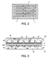
- Another interconnecting plate 1 has already been proposed [1]. She is represented in figure 2 with the circulation of the fluid represented by the arrows: its structure is of interdigitated type. It does not solve the problem of the mechanical bending mentioned for the plate 1 and can cause a hydraulic tearing of the electrode with which it is in contact.
- the object of the invention is to propose a solution that makes it possible to overcome all or part of the disadvantages of the existing interconnect plates at the cathode of a device for electrolysis of water at high temperature.
- Part of the cathode compartment according to the invention by which the steam is brought is thus constituted of one of the two chambers and a group of holes.
- the other group of holes and the other of the two chambers according to the invention constitute another part of the cathode compartment by which the hydrogen produced at the cathode is recovered.
- an electrolysis device may comprise a single electrolysis cell with a first interconnector in contact with its cathode and a second interconnector described below in contact with its anode.
- an interconnecting plate may comprise a first interconnector in contact with the cathode of an elementary electrolysis cell and a second interconnector in contact with the anode of the adjacent electrolysis cell.
- the current distribution at the cathode is optimal.
- the water vapor can be injected directly homogeneously at any point of the cathode through a group of holes, which which has the effect, contrary to the state of the art, a limitation of the concentration overvoltage.
- the adjacent chamber constitutes the chamber through which the water vapor is fed and the furthest chamber constitutes the collection chamber for the hydrogen produced by the electrolysis.
- the adjacent chamber is the collection chamber of the hydrogen produced by the electrolysis and the furthest chamber is the chamber through which water vapor is supplied.
- the holes are of circular section with a diameter of between 0.5 and 5 mm, preferably between 1.25 mm and 2.5 mm.
- the distance between the center of two adjacent holes is between 7 mm and 28 mm, preferably between 7 mm and 14 mm. With such distances, it is possible to obtain head losses of less than 200 millibars, according to electrolysis cells conforming to those used in the calculations with reference to the examples below.
- the holes are preferably aligned along lines parallel to each other and regularly spaced.
- the alternation can be furthermore made in such a way that the holes of the group emerging at the same time on the plane P1 and directly in the adjacent chamber are staggered with the holes of the group emerging at the same time on the plane P1 and in the chamber the farthest, each hole of the group opening on both the plane P1 and directly in the adjacent chamber being in the middle of four holes of the group opening on both the plane P1 and in the furthest chamber and vice versa.
- the four holes of one group form a square, the hole of the other group being in the middle of the square.
- the staggered alternation principle induces an even more homogeneous operation over the whole cell both from the point of view of the fluidics (supply of the water vapor and collection of the produced hydrogen), than of the thermal (distributed heat at any point in the electrolysis cell uniformly) or electrochemistry (identical electrolysis reaction at any point in the cell).
- the first interconnector is thus dimensionally simple to achieve.
- the electrolysis device of the invention may comprise a second device forming an electrical and fluidic interconnector consisting of a metal part delimited by at least one plane, said metal part comprising internally a chamber and a plurality of holes distributed over the surface, substantially perpendicular to the plane and opening at the same time on the latter and in the room, the plane of the second interconnector being in mechanical contact with the plane of the anode.
- the plane P2 of the second interconnector may be in direct mechanical contact with the plane of the anode.
- the electrolysis device of the water according to the invention may comprise a stack of elementary electrolysis cells each formed of a cathode, an anode and an electrolyte interposed between the cathode and the anode, a plate interconnector comprising a first and a second interconnector being arranged between two adjacent elementary cells, such that the plane P1 of the first interconnector is in mechanical contact with the cathode of one of the two elementary cells and the plane of the second interconnector is in mechanical contact with the anode of the other of the two elementary cells.
- the invention finally relates to a hydrogen production assembly comprising a plurality of electrolysis devices as described above.
- the high temperature electrolysis according to the invention can be carried out at temperatures of at least 450 ° C., typically between 700 ° C. and 1000 ° C.
- an electrolysis device comprises an elementary electrolysis cell formed of a cathode 2, an anode 4, and an electrolyte 6 interposed between the cathode and the anode.
- a first device 8.0 forming an electrical and fluidic interconnector consisting of a metal part 80 delimited by at least one plane P1.
- the metal part 80 internally comprises two chambers 81, 82 superimposed on one another and a plurality of holes 810, 820 substantially perpendicular to the plane P1 and divided into two groups.
- One of the groups of holes 810 opens on both the plane P1 and directly into the adjacent chamber 81 and the other group of the holes 820 opens on both the plane P1 and in the chamber 82 the farthest via channels 83.
- the plane P1 of the first interconnector 8.0 is in mechanical contact with the plane of the cathode 2.
- the water vapor injected by this chamber 82 then flows through the channels 83, then is progressively transformed into hydrogen in the porosity of the cathode 2 and thanks to the uniform supply of electric current over the entire cell surface by the Interconnect 8.0.
- One part of hydrogen is sampled uniformly by each of the holes 810 of the other group and then discharged through the chamber 81 on which the holes 810 open.
- the electrolysis device according to the invention as represented in figure 3 comprises, on the anode side 4, a second interconnector 8.1.
- This interconnector 8.1 also consists of a metal part 84 delimited by a plane P2 in direct mechanical contact with the plane of the anode 4.
- the metal part 84 internally comprises a chamber 85 and a plurality of holes 850 distributed on the surface, substantially perpendicular to the plane and opening on both this plane P2 and in the chamber 85.
- the oxygen produced at the anode 4 is collected by each of the holes 850 and is evacuated by the chamber 85.
- the metal part 80 is constituted by the assembly of three plates between them 80A, 80B, 80C parallel to each other.
- One of the plates 80A is pierced with two groups of holes 810, 820 arranged in lines parallel to each other and regularly spaced.
- the second plate 80B is also pierced but of a single group 800B of holes which communicates with the group of holes 820 of the first plate 80A by through tubular struts which constitute the channels 83.
- the space between the first plate 80A and the second plate 80b constitutes the chamber 81 for collecting hydrogen.
- the third plate 80C is solid and separated from a space with the second plate 80B which constitutes the other chamber 81 for supplying water vapor.
- the holes 810 are staggered with the holes 820, four holes 810 forming a square, with a hole 820 in the middle of the square.
- the current is brought and recovered at the terminals of the stack formed on the one hand by a first interconnector device 8.0 in contact with the cathode of the cell C1 and on the other hand by a second interconnector device 8.1 in contact with the cell C3.
- An interconnecting plate consisting of a second interconnector 8.1 and a first interconnector 8.0 is arranged between the cell C1 and the cell C2, the second interconnector 8.1 being in contact with the plane P2 of the anode of the cell C1 and the first interconnector 8.0 being in contact with the plane P1 of the cathode of the adjacent cell C2.
- the inventor has carried out finite element design calculations using ANSYS FLUENT software version 12.0 to validate the size, the number and the distribution of the holes according to the invention as a function of an imposed operating pressure.
- the calculations were made on a repetition pattern as presented in figure 5 , the repetition pattern being an isosceles triangle of length L defining the pitch of the pattern with a vertex coinciding with the center of a hole 820 through which water vapor arrives and another vertex coinciding with the center of a hole 810 through which the hydrogen produced is evacuated.
- Electrolysis cell Unit Value Cathode 2 Constitutive material YZS Ni- Thickness microns 315 Thermal conductivity W m -1 K -1 13.1 Electrical conductivity ⁇ -1 m -1 10 5 Porosity 0.37 Permeability m 2 10-13 crookedness 4 Current density A m -2 5300 Anode 3 Constitutive material LSM Thickness microns 20 Thermal conductivity W m -1 K -1 9.6 Electrical conductivity ⁇ -1 m -1 1 10 4 Porosity 0. 37 Permeability m 2 10-13 crookedness 3.0 4 Current density Am -2 2000 Electrolyte 4 Constitutive material YSZ Thickness microns 15 Resistivity ⁇ m 0.42
- the metal part 84 constituting the second interconnector 8.1 is in direct mechanical contact with the anode 4, as shown in FIG. figure 3 .
- the plane P2 of this second interconnector 8.1 is in direct mechanical contact with the plane of the anode as shown in FIG. figure 3 .
- the holes 850 for collecting the oxygen produced are alternately aligned in staggered rows exactly like all the holes 810, 820 for supplying steam and collecting oxygen respectively.
- Example 2 is identical to Example 1, with the exception of the pressure imposed: it is 30 bars and is the same at the outlet of chamber 81 for collecting hydrogen and at the outlet of chamber 85 for collecting oxygen.
- the calculations for this example 2 yield: L (mm) R (mm) ⁇ H 2 (mol fraction of H2) at the outlet Pressure drop ⁇ P cathode 2 (Pa) Current density (A / cm 2 ) Average Potential Nernst (V) Pressure drop ⁇ P anode 4 (Pa) 5.00 0.50 0894 6558.4 1017 0.97778 4486.2 5.00 1.00 0893 4607.2 1015 0.97775 2454.4 5.00 1.25 0886 4005.5 1013 0.97771 1850.4 10.00 1.00 0924 22068.0 1021 0.97439 17985.3 10.00 2.00 0919 15468.2 1014 0.97617 9799.8 10.00 2.50 0.901 13337.4 1003 0.97666 7497.8 15.00 1.50 0925 47517.4 1015
- Example 2 From this example 2, it can be concluded from Example 1 that at a pressure of 30 bar the evolutions observed for Example 1 remain the same, with the exception of reduced head losses at the cathode.
- Example 3 is identical to Example 1, with the exception that the plane of the anode is in direct mechanical contact with a grid of electrically conductive material instead of the perforated plate of the part 84 as shown in FIG. figure 3 .
- This conductive grid is here interposed between the part 84 and the plane of the anode.
- the grid is chosen so that it brings the current uniformly to the surface of the cathode. It is also chosen permeable so that its presence generates negligible pressure drops.
- Example 4 is identical to Example 3, with the exception of the imposed pressure: it is 30 bars and is the same at the outlet of chamber 81 for collecting hydrogen and at the outlet of chamber 85 for collecting oxygen.
- Example 3 From this example 4, it can be concluded from Example 3 that at a pressure of 30 bar the evolutions observed for Example 3 remain the same, with the exception of reduced cathode head losses. .
Landscapes
- Chemical & Material Sciences (AREA)
- Organic Chemistry (AREA)
- Chemical Kinetics & Catalysis (AREA)
- Electrochemistry (AREA)
- Engineering & Computer Science (AREA)
- Materials Engineering (AREA)
- Metallurgy (AREA)
- General Chemical & Material Sciences (AREA)
- Life Sciences & Earth Sciences (AREA)
- Hydrology & Water Resources (AREA)
- Environmental & Geological Engineering (AREA)
- Water Supply & Treatment (AREA)
- Inorganic Chemistry (AREA)
- Electrolytic Production Of Non-Metals, Compounds, Apparatuses Therefor (AREA)
Description
L'invention concerne un dispositif d'électrolyse de l'eau à haute température appelé aussi électrolyseur d'eau à haute température (EHT) appelé aussi électrolyseur de vapeur d'eau à haute température (EVHT).The invention relates to a high temperature water electrolysis device also called high temperature water electrolyser (EHT) also called high temperature steam electrolyser (EVHT).
Elle a trait plus particulièrement à une nouvelle architecture d'un électrolyseur EHT qui permet de rendre plus homogène son fonctionnement.It relates more particularly to a new architecture of an electrolyser EHT which makes it more homogeneous its operation.
Un électrolyseur de l'eau à haute température (EHT) comprend au moins une cellule électrochimique élémentaire formée d'un électrolyte, d'une cathode et d'une anode, l'électrolyte étant intercalé entre les l'anode et la cathode. L'électrolyte est étanche au gaz, isolant électronique et conducteur ionique. Les électrodes (anode et cathode) sont en matériau poreux et conducteurs électroniques.A high temperature water electrolyser (EHT) comprises at least one elementary electrochemical cell formed of an electrolyte, a cathode and an anode, the electrolyte being interposed between the anode and the cathode. The electrolyte is gastight, electronic insulator and ionic conductor. The electrodes (anode and cathode) are made of porous material and electronic conductors.
Un électrolyseur EHT comprend également des dispositifs d'interconnexion fluidique et électrique qui sont en contact électrique avec une ou des électrodes. Ces dispositifs d'interconnexion, assurent en général les fonctions d'amenée et collecte de courant et qui délimitent un ou des compartiments de circulation des gaz.An EHT electrolyser also includes fluidic and electrical interconnection devices that are in electrical contact with one or more electrodes. These interconnection devices, generally provide the functions of supply and collection of current and which delimit one or more compartments of gas circulation.
Ainsi, un compartiment dit cathodique a pour fonction la distribution du courant et de la vapeur d'eau ainsi que de la récupération de l'hydrogène à la cathode en contact.Thus, a so-called cathodic compartment has the function of distributing the current and water vapor as well as recovering the hydrogen at the cathode in contact.
Un compartiment dit anodique a pour fonction la distribution du courant ainsi que la récupération de l'oxygène produit à l'anode en contact. Un gaz drainant peut en outre être injecté en entrée du compartiment anodique pour évacuer l'oxygène produit. L'injection d'un gaz drainant a pour fonction supplémentaire de jouer le rôle de régulateur thermique.
On a représenté en
Les inconvénients majeurs de cette plaque à canaux peuvent être résumés comme suit.The major disadvantages of this channel plate can be summarized as follows.
Tout d'abord, elle ne permet pas d'utiliser la surface d'une cellule d'électrolyse de manière homogène. En effet, la réaction électrochimique se faisant prés de l'interface entre électrode et électrolyte, et nécessitant la présence sur le même lieu du gaz, des électrons et des ions impliqués, les zones sous les dents 10 du collecteur sont faciles à alimenter en électrons, mais difficiles à alimenter en gaz. Les paramètres contraignants sont la perméabilité de l'électrode en contact, son épaisseur et la largeur de la dent 10. De même, la zone sous le canal 11 est difficile à alimenter en électrons, les électrodes existantes à ce jour ayant une conductivité effective faible. Les paramètres contraignants sont la conductivité effective, l'épaisseur et la largeur du canal 11. L'inventeur est d'avis que le ratio R entre la surface d'amenée/collecte de courant et la surface d'amenée de vapeur d'eau ou de collecte des gaz produits est un paramètre indicateur de l'utilisation réelle de la surface de cellule. Dans le cas d'une plaque d'interconnection à canaux 1, le ratio R calculé comme ci-dessous est souvent inférieur à 50 %.First, it does not allow to use the surface of an electrolysis cell homogeneously. Indeed, the electrochemical reaction being close to the interface between electrode and electrolyte, and requiring the presence on the same place of the gas, electrons and ions involved, the areas under the
R = 1/ (1+ w/L), où w est la largeur du canal 11 et L la largeur de la dent 10.R = 1 / (1+ w / L), where w is the width of the
Ensuite, cette structure de plaque 1 implique des zones de production différenciées avec certaines zones dans lesquelles les densités de production et donc les densités de courant peuvent être très fortes, ceci pour une densité moyenne faible, et donc des sources de dégradation de performances localisées. Ceci est illustré au niveau local (échelle millimétrique) en
De même, cette structure de plaque 1 implique des inhomogénéités d'alimentation en vapeur d'eau des canaux 11 et obligent à une forte suralimentation de cette vapeur d'eau (on entre un surplus d'eau correspondant à plus 100 % de l'eau consommée) pour obtenir une alimentation pour l'ensemble des canaux 11 stable et homogène, ce qui rend difficile l'atteinte d'un taux d'utilisation en vapeur d'eau élevé. Le conditionnement de cette vapeur et sa mise en pression ont un impact non négligeable sur la consommation d'énergie associée à l'électrolyseur.Likewise, this
En outre, il existe un risque mécanique de mise en flexion d'une cellule si il y a un décalage géométrique important des dents d'une plaque interconnectrice 1 du côté de l'anode et celles d'une plaque du côté de la cathode, où s'il existe des défauts de planéité des dents pouvant poinçonner la cellule et la fissurer. Pour éviter ce risque, il faut une très grande précision dans le montage relatif des plaques de part et d'autre de la cellule et une très grande qualité de réalisation des dents.In addition, there is a mechanical risk of bending a cell if there is a significant geometric offset of the teeth of an
Par ailleurs, du coté de l'anode, la structure par canaux avec une entrée et une sortie n'a de raison d'être que lorsqu'un gaz drainant est utilisé pour évacuer l'oxygène produit vers la sortie. Le conditionnement de ce gaz drainant a lui aussi un coût énergétique significatif.Moreover, on the side of the anode, the channel structure with an inlet and an outlet has reason to be that when a draining gas is used to evacuate the oxygen produced to the outlet. The conditioning this draining gas also has a significant energy cost.
Enfin, cette structure de plaques nécessite une épaisseur de matière importante pour la zone de collection des gaz produits et une mise en forme (usinage) qui peuvent se révéler prohibitives. L'emploi de tôles minces et de l'emboutissage sont utilisées mais limitent de fait les possibilités de réalisation pour la largeur unitaire de dent et le pas entre dents. Aussi, l'inventeur considère qu'avec une telle plaque interconnectrice à canaux 1, la réduction de l'inhomogénéité des courants amenés à chaque cellule ne peut qu'être limitée.Finally, this plate structure requires a material thickness that is important for the collection zone of the gases produced and a shaping (machining) that can be prohibitive. The use of thin sheets and stamping are used but limit the possibilities of realization for the unit width of tooth and the pitch between teeth. Also, the inventor considers that with such an interconnecting plate with
Une autre plaque interconnectrice 1' a déjà été proposée [1]. Elle est représentée en
Le but de l'invention est de proposer une solution qui permette de s'affranchir de tout ou partie des inconvénients des plaques interconnectrices existantes à la cathode d'un dispositif d'électrolyse de l'eau à haute température.The object of the invention is to propose a solution that makes it possible to overcome all or part of the disadvantages of the existing interconnect plates at the cathode of a device for electrolysis of water at high temperature.
Pour ce faire l'invention a pour objet, un dispositif d'électrolyse de l'eau à haute température, comprenant :
- au moins une cellule d'électrolyse élémentaire formée d'une cathode, d'une anode, et d'un électrolyte intercalé entre la cathode et l'anode,
- un premier dispositif formant un interconnecteur électrique et fluidique consistant en une pièce métallique délimitée par au moins un plan P1, ladite pièce métallique comprenant intérieurement deux chambres, superposées l'une sur l'autre et une pluralité de trous répartis sur la surface, sensiblement perpendiculaires au plan et divisés en deux groupes, dont un groupe de trous débouche à la fois sur le plan P1 et directement dans la chambre adjacente et l'autre groupe des trous débouche à la fois sur le plan P1 et dans la chambre la plus éloignée par l'intermédiaire de canaux, le plan P1 du premier interconnecteur étant en contact mécanique avec le plan de la cathode.
- at least one elementary electrolysis cell formed of a cathode, an anode, and an electrolyte interposed between the cathode and the anode,
- a first device forming an electrical and fluidic interconnector consisting of a metal part delimited by at least one plane P1, said metal part comprising internally two chambers superimposed on one another and a plurality of holes distributed on the surface, substantially perpendicular in the plane and divided into two groups, one group of holes opens at the same time on the plane P1 and directly in the adjacent chamber and the other group of holes opens on both the plane P1 and in the furthest chamber by via channels, the plane P1 of the first interconnector being in mechanical contact with the plane of the cathode.
Une partie du compartiment cathodique selon l'invention par laquelle on amène la vapeur d'eau est ainsi constitué d'une des deux chambres et un groupe de trous. L'autre groupe de trous et l'autre des deux chambres selon l'invention constituent une autre partie du compartiment cathodique par laquelle on récupère l'hydrogène produit à la cathode.Part of the cathode compartment according to the invention by which the steam is brought is thus constituted of one of the two chambers and a group of holes. The other group of holes and the other of the two chambers according to the invention constitute another part of the cathode compartment by which the hydrogen produced at the cathode is recovered.
Dans le cadre de l'invention, toutes formes de trous variées peuvent être envisagées : trous à section circulaire, trous oblongs, trous sous la forme de fentes allongées....In the context of the invention, all forms of varied holes can be envisaged: circular section holes, oblong holes, holes in the form of elongated slots.
Dans le cadre de l'invention, on entend par interconnecteur fluidique et électrique, un système de connexion d'amenée ou de collecte de courant et d'amenée et de collecte d'un fluide à une électrode d'une cellule d'électrolyse. Ainsi, un dispositif d'électrolyse selon l'invention peut comprendre une seule cellule d'électrolyse avec un premier interconnecteur en contact avec sa cathode et un deuxième interconnecteur décrit ci-dessous en contact avec son anode. De même, comme décrit par la suite, dans un empilement de cellules d'électrolyse selon l'invention, une plaque interconnectrice peut comprendre un premier interconnecteur en contact avec la cathode d'une cellule d'électrolyse élémentaire et un deuxième interconnecteur en contact avec l'anode de la cellule d'électrolyse adjacente.In the context of the invention, the term "fluidic and electrical interconnector" means a connection system for supplying or collecting current and supplying and collecting a fluid to an electrode. of an electrolysis cell. Thus, an electrolysis device according to the invention may comprise a single electrolysis cell with a first interconnector in contact with its cathode and a second interconnector described below in contact with its anode. Similarly, as described below, in a stack of electrolysis cells according to the invention, an interconnecting plate may comprise a first interconnector in contact with the cathode of an elementary electrolysis cell and a second interconnector in contact with the anode of the adjacent electrolysis cell.
On s'affranchit des inconvénients de la traditionnelle architecture de plaque interconnectrice à canaux selon l'état de l'art telle que présentée en préambule.It overcomes the disadvantages of the traditional interconnecting channel plate architecture according to the state of the art as presented in the preamble.
Ainsi, grâce à l'invention, on obtient comparativement aux architectures d'électrolyseur EHT selon l'état de l'art une densité de production uniforme par cellule d'électrolyse et un meilleur taux d'utilisation (ou de conversion) de vapeur d'eau.Thus, by virtue of the invention, a uniform production density per electrolytic cell and a better utilization rate (or conversion rate) of steam of the electrolytic cell are obtained compared to the electrolysis architectures EHT according to the state of the art. 'water.
En effet, grâce à la pluralité de trous débouchant sur le plan de la cathode, on permet tout d'abord à toute la surface de cellule d'avoir un comportement électrique homogène en tout point avec une résistance de contact électrique limitée entre cathode et premier interconnecteur. Autrement dit, la distribution du courant à la cathode est optimale.Indeed, thanks to the plurality of holes opening on the plane of the cathode, firstly allows the entire cell surface to have a homogeneous electrical behavior at any point with a limited electrical contact resistance between cathode and first interconnector. In other words, the current distribution at the cathode is optimal.
De même, du fait de la superposition des chambres et de la pluralité des trous, on peut injecter la vapeur d'eau directement de manière homogène en tout point de la cathode au travers d'un groupe de trous, ce qui a pour effet, contrairement à l'état de l'art, une limitation de la surtension de concentration.Similarly, due to the superposition of the chambers and the plurality of holes, the water vapor can be injected directly homogeneously at any point of the cathode through a group of holes, which which has the effect, contrary to the state of the art, a limitation of the concentration overvoltage.
Pour l'injection de la vapeur d'eau, on peut prévoir deux variantes.For the injection of water vapor, two variants can be provided.
Selon une première variante, la chambre adjacente constitue la chambre par laquelle la vapeur d'eau est amenée et la chambre la plus éloignée constitue la chambre de collecte de l'hydrogène produit par l'électrolyse.According to a first variant, the adjacent chamber constitutes the chamber through which the water vapor is fed and the furthest chamber constitutes the collection chamber for the hydrogen produced by the electrolysis.
Selon une deuxième variante alternative, la chambre adjacente constitue la chambre de collecte de l'hydrogène produit par l'électrolyse et la chambre la plus éloignée constitue la chambre par laquelle la vapeur d'eau est amenée.According to a second alternative variant, the adjacent chamber is the collection chamber of the hydrogen produced by the electrolysis and the furthest chamber is the chamber through which water vapor is supplied.
Avantageusement, les trous sont à section circulaire avec un diamètre compris entre 0.5 et 5 mm, de préférence compris entre 1.25 mm et 2.5 mm.Advantageously, the holes are of circular section with a diameter of between 0.5 and 5 mm, preferably between 1.25 mm and 2.5 mm.
Avantageusement encore, la distance entre le centre de deux trous adjacents est comprise entre 7 mm et 28 mm, de préférence compris entre 7 mm et 14 mm. Avec de telles distances, on peut obtenir des pertes de charge de moins de 200 millibars, selon des cellules d'électrolyse conformes à celles utilisées dans les calculs en référence aux exemples ci-après.Advantageously, the distance between the center of two adjacent holes is between 7 mm and 28 mm, preferably between 7 mm and 14 mm. With such distances, it is possible to obtain head losses of less than 200 millibars, according to electrolysis cells conforming to those used in the calculations with reference to the examples below.
Les trous sont de préférence alignés selon des lignes parallèles entre elles et régulièrement espacées.The holes are preferably aligned along lines parallel to each other and regularly spaced.
Pour rendre encore plus homogène le fonctionnement à la cathode, on prévoit avantageusement une ligne de groupe trous débouchant à la fois sur le plan P1 et directement dans la chambre adjacente est alternée avec une ligne de groupe de trous qui débouche à la fois sur le plan P1 et dans la chambre la plus éloignée.To make the cathode operation even more homogeneous, it is advantageous to provide a hole group line emerging at the same time on the plane P1 and directly in the adjacent chamber is alternated with a group of hole line which opens both on the plane P1 and in the furthest room.
L'alternance peut être en outre réalisée de telle manière que les trous du groupe débouchant à la fois sur le plan P1 et directement dans la chambre adjacente sont en quinconce avec les trous du groupe débouchant à la fois sur le plan P1 et dans la chambre la plus éloignée, chaque trou du groupe débouchant à la fois sur le plan P1 et directement dans la chambre adjacente étant au milieu de quatre trous du groupe débouchant à la fois sur le plan P1 et dans la chambre la plus éloignée et vice-versa.The alternation can be furthermore made in such a way that the holes of the group emerging at the same time on the plane P1 and directly in the adjacent chamber are staggered with the holes of the group emerging at the same time on the plane P1 and in the chamber the farthest, each hole of the group opening on both the plane P1 and directly in the adjacent chamber being in the middle of four holes of the group opening on both the plane P1 and in the furthest chamber and vice versa.
De préférence encore, les quatre trous d'un groupe forment un carré, le trou de l'autre groupe étant au milieu du carré. Le principe de répétition par alternance en quinconce induit un fonctionnement encore plus homogène sur toute la cellule tant du point de vue de la fluidique (amenée de la vapeur d'eau et collecte de l'hydrogène produit), que de la thermique (chaleur répartie en tout point de la cellule d'électrolyse uniformément) ou de l'électrochimie (réaction d'électrolyse identique en tout point de la cellule). En outre, le premier interconnecteur est ainsi de dimensionnement simple à réaliser.More preferably, the four holes of one group form a square, the hole of the other group being in the middle of the square. The staggered alternation principle induces an even more homogeneous operation over the whole cell both from the point of view of the fluidics (supply of the water vapor and collection of the produced hydrogen), than of the thermal (distributed heat at any point in the electrolysis cell uniformly) or electrochemistry (identical electrolysis reaction at any point in the cell). In addition, the first interconnector is thus dimensionally simple to achieve.
Le dispositif d'électrolyse de l'invention peut comprendre un deuxième dispositif formant un interconnecteur électrique et fluidique consistant en une pièce métallique délimitée par au moins un plan, ladite pièce métallique comprenant intérieurement une chambre et une pluralité de trous répartis sur la surface, sensiblement perpendiculaires au plan et débouchant à la fois sur ce dernier et dans la chambre, le plan du deuxième interconnecteur étant en contact mécanique avec le plan de l'anode.The electrolysis device of the invention may comprise a second device forming an electrical and fluidic interconnector consisting of a metal part delimited by at least one plane, said metal part comprising internally a chamber and a plurality of holes distributed over the surface, substantially perpendicular to the plane and opening at the same time on the latter and in the room, the plane of the second interconnector being in mechanical contact with the plane of the anode.
Le plan P2 du deuxième interconnecteur peut être en contact mécanique direct avec le plan de l'anode.The plane P2 of the second interconnector may be in direct mechanical contact with the plane of the anode.
Le dispositif d'électrolyse de l'eau selon l'invention peut comprendre un empilement de cellules d'électrolyse élémentaires formées chacune d'une cathode, d'une anode et d'un électrolyte intercalé entre la cathode et l'anode, une plaque interconnectrice comprenant un premier et un deuxième interconnecteur étant agencée entre deux cellules élémentaires adjacentes, tel que le plan P1 du premier interconnecteur est en contact mécanique avec la cathode d'une des deux cellules élémentaires et le plan du deuxième interconnecteur est en contact mécanique avec l'anode de l'autre des deux cellules élémentaires.The electrolysis device of the water according to the invention may comprise a stack of elementary electrolysis cells each formed of a cathode, an anode and an electrolyte interposed between the cathode and the anode, a plate interconnector comprising a first and a second interconnector being arranged between two adjacent elementary cells, such that the plane P1 of the first interconnector is in mechanical contact with the cathode of one of the two elementary cells and the plane of the second interconnector is in mechanical contact with the anode of the other of the two elementary cells.
L'invention concerne enfin un ensemble de production d'hydrogène comprenant une pluralité de dispositifs d'électrolyse tels que décrits ci-dessus.The invention finally relates to a hydrogen production assembly comprising a plurality of electrolysis devices as described above.
D'autres avantages et caractéristiques ressortiront mieux à la lecture de la description détaillée faite ci-dessous en référence aux figures parmi lesquelles :
- la
figure 1 est une vue schématique de face d'une plaque interconnectrice d'un électrolyseur EHT selon l'état de l'art, - la
figure 1A est une vue de détail en coupe d'une plaque interconnectrice selon lafigure 1 , - la
figure 1B est une vue analogue à lafigure 1A montrant les lignes de courant parcourant la plaque, - la
figure 2 est une vue schématique de face d'une autre plaque interconnectrice d'un électrolyseur selon l'état de l'art, - la
figure 3 est une vue schématique en coupe d'un dispositif d'électrolyse selon l'invention à une cellule d'électrolyse, - la
figure 4 est une vue en perspective interne en transparence d'un interconnecteur fluidique et électrique conforme à l'invention, - la
figure 5 est une vue de dessus interne en transparence de l'interconnecteur selon lafigure 4 , - la
figure 6 est une vue schématique en coupe d'un dispositif d'électrolyse selon l'invention à un empilement de cellules d'électrolyse.
- the
figure 1 is a diagrammatic front view of an interconnecting plate of an electrolyser EHT according to the state of the art, - the
Figure 1A is a detailed sectional view of an interconnecting plate according to thefigure 1 , - the
Figure 1B is a view similar to theFigure 1A showing the current lines running through the plate, - the
figure 2 is a diagrammatic front view of another interconnecting plate of an electrolyser according to the state of the art, - the
figure 3 is a schematic sectional view of an electrolysis device according to the invention to an electrolysis cell, - the
figure 4 is an internal perspective view in transparency of a fluidic and electrical interconnector according to the invention, - the
figure 5 is an internal transparent top view of the interconnector according to thefigure 4 , - the
figure 6 is a schematic sectional view of an electrolysis device according to the invention to a stack of electrolysis cells.
Les plaques interconnectrices 1, 1' d'électrolyseurs EHT selon l'état de l'art et représentées en
Les symboles et les flèches de parcours de vapeur d'eau, hydrogène et d'oxygène sont montrés dans l'ensemble des figures à des fins de clarté.Symbols and arrows of course of water vapor, hydrogen and oxygen are shown throughout the figures for the sake of clarity.
L'électrolyse à haute température selon l'invention peut être réalisée à des températures d'au moins 450°C, typiquement comprises entre 700°C et 1000°C.The high temperature electrolysis according to the invention can be carried out at temperatures of at least 450 ° C., typically between 700 ° C. and 1000 ° C.
Tel que représenté en
Selon l'invention, il est prévu un premier dispositif 8.0 formant un interconnecteur électrique et fluidique consistant en une pièce métallique 80 délimitée par au moins un plan P1.According to the invention, there is provided a first device 8.0 forming an electrical and fluidic interconnector consisting of a
La pièce métallique 80 comprend intérieurement deux chambres 81, 82 superposées l'une sur l'autre et une pluralité de trous 810, 820 sensiblement perpendiculaires au plan P1 et divisés en deux groupes.The
Un des groupes de trous 810 débouche à la fois sur le plan P1 et directement dans la chambre adjacente 81 et l'autre groupe des trous 820 débouche à la fois sur le plan P1 et dans la chambre 82 la plus éloignée par l'intermédiaire de canaux 83.One of the groups of
Le plan P1 du premier interconnecteur 8.0 est en contact mécanique avec le plan de la cathode 2.The plane P1 of the first interconnector 8.0 is in mechanical contact with the plane of the
Tel que représenté en
Comme illustré à l'aide de la flèche et des symboles H2 et H2O en
Une partie d'hydrogène est prélevée de manière uniforme par chacun des trous 810 de l'autre groupe puis évacuée par la chambre 81 sur laquelle les trous 810 débouchent.One part of hydrogen is sampled uniformly by each of the
Le dispositif d'électrolyse selon l'invention tel que représenté en
Cet interconnecteur 8.1 consiste également en une pièce métallique 84 délimitée par un plan P2 en contact mécanique direct avec le plan de l'anode 4.This interconnector 8.1 also consists of a
La pièce métallique 84 comprenant intérieurement une chambre 85 et une pluralité de trous 850 répartis sur la surface, sensiblement perpendiculaires au plan et débouchant à la fois sur ce plan P2 et dans la chambre 85.The
Comme illustré à l'aide de la flèche et du symbole O2 en
On a représenté en
La pièce métallique 80 est constituée par l'assemblage de trois plaques entre elles 80A, 80B, 80C parallèlement l'une à l'autre. L'une des plaques 80A est percée des deux groupes de trous 810, 820 agencés selon des lignes parallèles entre elles et régulièrement espacées.The
La deuxième plaque 80B est également percée mais d'un seul groupe 800B de trous qui communique avec le groupe de trous 820 de la première plaque 80A par l'intermédiaire d'entretoises tubulaires qui constituent les canaux 83.The
L'espace entre la première plaque 80A et la deuxième plaque 80b constitue la chambre 81 de collecte de l'hydrogène.The space between the
La troisième plaque 80C est pleine et séparée d'un espace avec la deuxième plaque 80B qui constitue l'autre chambre 81 d'amenée de la vapeur d'eau.The
Comme plus visible à la
On a représenté schématiquement en
Plus exactement, le courant est amené et récupéré aux bornes de l'empilement constituées d'une part par un premier dispositif interconnecteur 8.0 en contact avec la cathode de la cellule C1 et d'autre part par un deuxième dispositif interconnecteur 8.1 en contact avec la cellule C3.More precisely, the current is brought and recovered at the terminals of the stack formed on the one hand by a first interconnector device 8.0 in contact with the cathode of the cell C1 and on the other hand by a second interconnector device 8.1 in contact with the cell C3.
Une plaque interconnectrice constituée d'un deuxième interconnecteur 8.1 et d'un premier interconnecteur 8.0 est agencée entre la cellule C1 et la cellule C2, le deuxième interconnecteur 8.1 étant en contact avec le plan P2 de l'anode de la cellule C1 et le premier interconnecteur 8.0 étant en contact avec le plan P1 de la cathode de la cellule C2 adjacente.An interconnecting plate consisting of a second interconnector 8.1 and a first interconnector 8.0 is arranged between the cell C1 and the cell C2, the second interconnector 8.1 being in contact with the plane P2 of the anode of the cell C1 and the first interconnector 8.0 being in contact with the plane P1 of the cathode of the adjacent cell C2.
Cela est réalisé de manière identique entre les deux cellules C2 et C3 adjacentes.This is done identically between the two adjacent cells C2 and C3.
L'inventeur a réalisé des calculs de dimensionnement par éléments finis à l'aide du logiciel d'ANSYS FLUENT version 12.0 pour valider la taille, le nombre et la répartition des trous selon l'invention en fonction d'une pression de fonctionnement imposée.The inventor has carried out finite element design calculations using ANSYS FLUENT software version 12.0 to validate the size, the number and the distribution of the holes according to the invention as a function of an imposed operating pressure.
On précise que les calculs ont été faits sur un motif de répétition tel que présenté en
On précise également, que pour chaque calcul, tous les trous 820, 810, 850 respectivement d'amenée de vapeur d'eau, d'évacuation de l'hydrogène produit et d'évacuation de l'oxygène sortie ont le même rayon R.It is also specified that for each calculation, all the
Les résultats de ces calculs sont présentés ci-après.The results of these calculations are presented below.
On précise tout d'abord que les conditions opératoires sont les suivantes :
• Voltage de 1.17V par cellule d'électrolyse.
• Température d'entrée de fluide injecté dans la chambre 82 de 800°C.
• Composition du mélange de fluide injecté côté cathode 2 : 10 % de H2 et 90 % de H2O avec un débit correspondant à une sur stoechiométrie de 10 % en H2O pour une densité de courant i=1 A/cm2, soit un débit molaire de vapeur d'eau: ![]()
Équation dans laquelle L est le pas du motif de calcul évoqué ci-dessus et exprimée en cm et F est la constante de Faraday exprimée en Coulomb par mole.
• Côté anode 4, aucun gaz drainant.
• Tous les gaz sont considérés comme incompressibles.
• Caractéristiques de la cellule d'électrolyse comme suit dans le tableau :
• Voltage of 1.17V per electrolysis cell.
• Fluid inlet temperature injected into the
• composition of the fluid mixture injected on the cathode side 2: 10% H 2 and 90% H 2 O with a flow rate corresponding to an on stoichiometry of 10% H 2 O for a current density i = 1 A / cm 2 , ie a molar flow of water vapor: ![]()
Equation in which L is the step of the calculation pattern mentioned above and expressed in cm and F is the Faraday constant expressed in Coulomb per mole.
•
• All gases are considered incompressible.
• Characteristics of the electrolysis cell as follows in the table:
La pièce métallique 84 constituant le deuxième interconnecteur 8.1 est en contact mécanique direct avec l'anode 4, comme représenté en
Le plan P2 de ce deuxième interconnecteur 8.1 est en contact mécanique direct avec le plan de l'anode comme représenté en
Les trous 850 de collecte de l'oxygène produit sont alignés en alternance en quinconce exactement comme l'ensemble des trous 810, 820 d'amenée de vapeur d'eau et de collecte d'oxygène respectivement.The
Une même pression de 1 bar est imposée en sortie de chambre 81 de collecte d'hydrogène et en sortie de chambre 85 de collecte d'oxygène.The same pressure of 1 bar is imposed at the outlet of
Les calculs pour cet exemple 1 donnent :
De cet exemple 1, on peut en conclure que :
- la densité de courant est peu sensible à la valeur du pas L,
- la densité de courant est plus sensible au rayon des trous R. Plus le rayon des trous R est petit et meilleure est la distribution du courant. Par contre, avec un R plus grand, l'évacuation de l'oxygène se fait mieux et la pression diminue du côté de l'anode 4 (pertes de
charge ΔP anode 4 augmentent), ce qui contribue à un potentiel de Nernst plus faible. Ainsi, la densité de courant augmente relativement avec R. - les pertes de charge à la
cathode ΔP cathode 2 sont relativement élevées. Elles augmentent lorsque le pas L augmente ou le rayon du trou R diminue.
- the current density is insensitive to the value of the pitch L,
- the current density is more sensitive to the radius of the holes R. The smaller the radius of the holes R, the better the distribution of the current. On the other hand, with a larger R, the evacuation of oxygen is better and the pressure decreases on the side of the anode 4 (pressure losses Δ
P anode 4 increase), which contributes to a lower Nernst potential. Thus, the current density increases relatively with R. - the losses at the
cathode Δ P 2 cathode are relatively high. They increase when the pitch L increases or the radius of the hole R decreases.
L'exemple 2 est identique à l'exemple 1, à l'exception de la pression imposée: elle est de 30 bars et est la même en sortie de chambre 81 de collecte d'hydrogène et en sortie de chambre 85 de collecte d'oxygène. Les calculs pour cet exemple 2 adonnent :
De cet exemple 2, on peut en conclure comparativement à l'exemple 1, qu'à une pression de 30 bars les évolutions constatées pour l'exemple 1 restent les mêmes, à l'exception des pertes de charge à la cathode qui sont réduites.From this example 2, it can be concluded from Example 1 that at a pressure of 30 bar the evolutions observed for Example 1 remain the same, with the exception of reduced head losses at the cathode.
L'exemple 3 est identique à l'exemple 1, à l'exception du fait que le plan de l'anode est en contact mécanique direct avec une grille en matériau conducteur électrique au lieu de la plaque perforée de la pièce 84 comme représentée en
Les calculs pour cet exemple 3 donnent :
De cet exemple 3, on peut en conclure que :
- comparativement à l'exemple 1, la densité de courant est légèrement plus forte lorsqu'on met une grille directement en contact mécanique avec l'anode. Cela s'explique par le fait qu'avec un élément grille, on obtient une pression d'oxygène plus faible et donc un potentiel Nernst plus faible.
- comme dans les exemples 1
et 2, la densité de courant est peu sensible à la valeur du pas L. - la densité de courant augmente quand le rayon des trous R diminue, car la distribution du courant est améliorée du côté de la cathode.
- les pertes de charge à l'anode ΔP anode sont faibles.
- les pertes de charge ΔP à la cathode sont relativement élevées. Elles augmentent lorsque le pas L augmente ou le rayon du trou R diminue.
- compared to Example 1, the current density is slightly higher when a grid is placed directly in mechanical contact with the anode. This is explained by the fact that with a grid element, one obtains a lower oxygen pressure and therefore a lower Nernst potential.
- as in Examples 1 and 2, the current density is insensitive to the value of the pitch L.
- the current density increases as the radius of the holes R decreases because the current distribution is improved on the cathode side.
- pressure drops in the anode Δ P anode are low.
- the pressure drops Δ P at the cathode are relatively high. They increase when the pitch L increases or the radius of the hole R decreases.
L'exemple 4 est identique à l'exemple 3, à l'exception de la pression imposée: elle est de 30 bars et est la même en sortie de chambre 81 de collecte d'hydrogène et en sortie de chambre 85 de collecte d'oxygène.Example 4 is identical to Example 3, with the exception of the imposed pressure: it is 30 bars and is the same at the outlet of
Les calculs pour cet exemple 4 donnent :
De cet exemple 4, on peut en conclure comparativement à l'exemple 3, qu'à une pression de 30 bars les évolutions constatées pour l'exemple 3 restent les mêmes, à l'exception des pertes de charge à la cathode qui sont réduites.From this example 4, it can be concluded from Example 3 that at a pressure of 30 bar the evolutions observed for Example 3 remain the same, with the exception of reduced cathode head losses. .
Les conclusions que l'on peut tirer des exemples 1 à 4 ci-dessus sont que la performance d'électrolyse proprement dite semble assez peu sensible au dimensionnement du motif de base (valeur du pas L) puisque la fraction molaire d'hydrogène en sortie χH
Par contre, les performances hydrauliques semblent être sensibles à la pression imposée, les pertes de charge étant plus élevées à une pression plus faible (1 bar dans les exemples). L'inventeur en conclut donc qu'il parait préféré de faire fonctionner un dispositif d'électrolyse selon l'invention sous pression élevée.On the other hand, the hydraulic performances seem to be sensitive to the imposed pressure, the pressure losses being higher at a lower pressure (1 bar in the examples). The inventor therefore concludes that it seems preferable to operate an electrolysis device according to the invention under high pressure.
D'autres améliorations peuvent être apportées sans pour autant sortir du cadre de l'invention.Other improvements can be made without departing from the scope of the invention.
Bien que non détaillé, il va de soi qu'un mode de réalisation avec la vapeur d'eau alimentée par la chambre 81 et une récupération de l'hydrogène produit par la chambre 82 fonctionne.Although not detailed, it goes without saying that an embodiment with the water vapor fed by the
-
[1] :
Xiango Li, International Journal of hydrogen Energy 30 (2005) 359-371 Li Xiango, International Journal of Hydrogen Energy 30 (2005) 359-371
Claims (14)
- Device for high temperature electrolysis of water, comprising:- at least one elementary electrolysis cell formed from a cathode (2), an anode (4), and an electrolyte (6) intermediate between the cathode and the anode,- a first device (8.0) forming an electric and fluid interconnector composed of a metallic part (80) delimited by at least one plane P1, said metallic part comprising two internal chambers (81, 82), superposed one on the other and a plurality of holes (810, 820) distributed around the surface, approximately perpendicular to the plane and divided into two groups, one of the groups of holes (810) opens up onto plane P1 and directly into the adjacent chamber (81) and the other group of holes (820) opens up onto plane P1 and also in the furthest chamber (82) through channels (83), the plane P1 of the first interconnector being in mechanical contact with the plane of the cathode (2).
- Device for electrolysis of water according to claim 1, in which the adjacent chamber is the chamber through which steam is delivered and the furthest chamber is the chamber through which hydrogen produced by electrolysis is collected.
- Device for electrolysis of water according to claim 1, in which the adjacent chamber is the chamber through which hydrogen produced by electrolysis is collected and the furthest chamber is the chamber through which steam is delivered.
- Device for electrolysis of water according to one of the previous claims, in which the holes (810, 820) have a circular cross-section with a diameter of between 0.5 and 5 mm, and preferably between 1.25 mm and 2.5 mm.
- Device for electrolysis of water according to one of the previous claims, in which the distance between the centre of two adjacent holes is between 7 mm and 28 mm, and preferably between 7 mm et 14 mm.
- Device for electrolysis of water according to one of the previous claims, in which the holes are aligned along parallel lines at equal intervals.
- Device for electrolysis of water according to claim 6, in which one group of aligned holes (810) opening up onto plane P1 and directly into the adjacent chamber alternates with another group of aligned holes (820) that opens up onto plane P1 and into the furthest chamber.
- Device for electrolysis of water according to claim 7, in which alternation is achieved such that the holes in the group (810) opening up both on plane P1 and directly in the adjacent chamber are staggered with the holes (820) opening up both on plane P1 and in the furthest chamber, each hole in the group (810) opening up both onto plane P1 and directly in the adjacent chamber being in the middle of four holes (820) in the group opening up both onto plane P1 and in the furthest chamber, and vice versa.
- Device for electrolysis of water according to claim 8, in which the four holes (810) in a group form a square, the hole (820) in the other group being in the middle of the square.
- Device for electrolysis of water according to one of the previous claims, comprising a second device (8.1) forming an electrical and fluid interconnector composed of a metal part (84) delimited by at least one plane P2, said metallic part comprising an internal chamber (85) and a plurality of holes (850) distributed over the entire surface, approximately perpendicular to the plane and opening up onto this plane P2 and into the chamber (85), the plane P2 of the second interconnector (8.1) being in mechanical contact with the plane of the anode (4).
- Device for electrolysis of water according to claim 10, in which the plane P2 is in direct mechanical contact with the plane of the anode.
- Device for electrolysis of water according to claim 10, in which the plane P2 is in direct mechanical contact with a gate made of an electrically conducting material, the gate being itself in direct mechanical contact with the plane of the anode.
- Device for electrolysis of water at high temperature according to one of claims 10 to 12, comprising a stack of elementary electrolysis cells each formed from a cathode, an anode and an electrolyte placed between the cathode and the anode, an interconnecting plate comprising a first (8.0) and a second (8.1) interconnector being formed between two adjacent elementary cells such that the plane P1 of the first interconnector is in mechanical contact with the cathode of one of the two elementary cells and the plane P2 of the second interconnector is in mechanical contact with the anode of the other of the two elementary cells.
- Hydrogen production assembly comprising a plurality of electrolysis devices according to claim 13.
Priority Applications (1)
| Application Number | Priority Date | Filing Date | Title |
|---|---|---|---|
| PL11707435T PL2545207T3 (en) | 2010-03-12 | 2011-03-11 | Device for high-temperature water electrolysis having improved operation |
Applications Claiming Priority (2)
| Application Number | Priority Date | Filing Date | Title |
|---|---|---|---|
| FR1051781A FR2957359B1 (en) | 2010-03-12 | 2010-03-12 | HIGH-TEMPERATURE WATER ELECTROLYSIS DEVICE WITH IMPROVED OPERATION |
| PCT/EP2011/053728 WO2011110679A1 (en) | 2010-03-12 | 2011-03-11 | Device for high-temperature water electrolysis having improved operation |
Publications (2)
| Publication Number | Publication Date |
|---|---|
| EP2545207A1 EP2545207A1 (en) | 2013-01-16 |
| EP2545207B1 true EP2545207B1 (en) | 2014-04-02 |
Family
ID=42711784
Family Applications (1)
| Application Number | Title | Priority Date | Filing Date |
|---|---|---|---|
| EP11707435.1A Not-in-force EP2545207B1 (en) | 2010-03-12 | 2011-03-11 | Device for high-temperature water electrolysis having improved operation |
Country Status (12)
| Country | Link |
|---|---|
| US (1) | US9200374B2 (en) |
| EP (1) | EP2545207B1 (en) |
| JP (1) | JP5822852B2 (en) |
| KR (1) | KR20130008544A (en) |
| BR (1) | BR112012022388A2 (en) |
| CA (1) | CA2792511A1 (en) |
| DK (1) | DK2545207T3 (en) |
| ES (1) | ES2477520T3 (en) |
| FR (1) | FR2957359B1 (en) |
| PL (1) | PL2545207T3 (en) |
| WO (1) | WO2011110679A1 (en) |
| ZA (1) | ZA201206457B (en) |
Families Citing this family (8)
| Publication number | Priority date | Publication date | Assignee | Title |
|---|---|---|---|---|
| FR2957361B1 (en) | 2010-03-12 | 2012-04-20 | Commissariat Energie Atomique | HIGH TEMPERATURE (EHT) ELECTROLYSIS WITH ENHANCED OPERATING SAFETY |
| FR2957363B1 (en) | 2010-03-12 | 2012-04-20 | Commissariat Energie Atomique | HIGH TEMPERATURE ELECTROLYSIS ARCHITECTURE WITH HIGH ELECTROLYTIC CELL TARGET GENERATION AND LIMIT CELL DEGRADATION RATES |
| FR2976591B1 (en) | 2011-06-16 | 2013-07-12 | Commissariat Energie Atomique | SIMPLIFIED REALIZATION INTERCONNECTOR MODULE FOR HIGH-TEMPERATURE WATER ELECTROLYSIS DEVICE |
| FR3001232B1 (en) * | 2013-01-24 | 2015-02-20 | Commissariat Energie Atomique | METHOD OF MAKING AN INTERCONNECTOR MODULE FOR A HIGH TEMPERATURE WATER ELECTROLYSIS DEVICE OR SOFC. |
| JP6084532B2 (en) * | 2013-07-12 | 2017-02-22 | 株式会社東芝 | Hydrogen production equipment |
| FR3024985B1 (en) * | 2014-08-22 | 2020-01-17 | Commissariat A L'energie Atomique Et Aux Energies Alternatives | HIGH TEMPERATURE ELECTROLYSIS OR CO-ELECTROLYSIS PROCESS, PROCESS FOR PRODUCING ELECTRICITY BY SOFC FUEL CELL, INTERCONNECTORS, REACTORS AND RELATED OPERATING METHODS. |
| US11181076B2 (en) | 2016-03-03 | 2021-11-23 | Kevin Michael Weldon | Rocket engine bipropellant supply system including an electrolyzer |
| JP2020147843A (en) * | 2019-03-06 | 2020-09-17 | 株式会社東芝 | Electrolytic tank and hydrogen production apparatus |
Family Cites Families (13)
| Publication number | Priority date | Publication date | Assignee | Title |
|---|---|---|---|---|
| JPH07145492A (en) * | 1993-11-22 | 1995-06-06 | Fuji Electric Co Ltd | Steam electrolytic cell |
| EP1482585B1 (en) | 2002-03-04 | 2012-06-20 | Mitsubishi Materials Corporation | Solid oxide type fuel cell and separator |
| US6997299B2 (en) * | 2003-07-28 | 2006-02-14 | Magna Powertrain, Inc. | Hydraulic clutch actuation system |
| JP2006328527A (en) * | 2005-04-26 | 2006-12-07 | Honda Motor Co Ltd | Apparatus for producing hydrogen |
| US7381313B2 (en) * | 2005-06-30 | 2008-06-03 | General Electric Company | Integrated hydrogen production and processing system and method of operation |
| JP2007227317A (en) * | 2006-02-27 | 2007-09-06 | Hitachi Ltd | Fuel cell, battery mounting member, and electronic equipment that mounts it |
| JP2008243741A (en) * | 2007-03-28 | 2008-10-09 | Toshiba Corp | Fuel cell |
| WO2008153829A1 (en) * | 2007-05-29 | 2008-12-18 | Transphorm, Inc. | Electrolysis transistor |
| FR2921389B1 (en) | 2007-09-25 | 2010-03-12 | Commissariat Energie Atomique | HIGH TEMPERATURE ELECTROLYSER WITH HYDROGEN RECOVERY DEVICE. |
| FR2921390B1 (en) | 2007-09-25 | 2010-12-03 | Commissariat Energie Atomique | HIGH TEMPERATURE ELECTROLYSIS HOMOGENIZING TEMPERATURE DEVICE. |
| FR2957362B1 (en) | 2010-03-12 | 2012-04-20 | Commissariat Energie Atomique | ELECTROCHEMISTRY PROCESS WITH IMPROVED YIELD AND ELECTROCHEMICAL REACTOR SUCH AS A HIGH-TEMPERATURE ELECTROLYSER (EHT) ASSOCIATED |
| FR2957360B1 (en) | 2010-03-12 | 2012-04-20 | Commissariat Energie Atomique | HIGH TEMPERATURE ELECTROLYSER (EHT) COMPRISING A PLURALITY OF CELLS, WITH IMPROVED OPERATION IN THE EVENT OF A BREAK OF AT LEAST ONE CELL AND IN LIFE |
| FR2957361B1 (en) | 2010-03-12 | 2012-04-20 | Commissariat Energie Atomique | HIGH TEMPERATURE (EHT) ELECTROLYSIS WITH ENHANCED OPERATING SAFETY |
-
2010
- 2010-03-12 FR FR1051781A patent/FR2957359B1/en not_active Expired - Fee Related
-
2011
- 2011-03-11 WO PCT/EP2011/053728 patent/WO2011110679A1/en active Application Filing
- 2011-03-11 PL PL11707435T patent/PL2545207T3/en unknown
- 2011-03-11 JP JP2012556537A patent/JP5822852B2/en not_active Expired - Fee Related
- 2011-03-11 CA CA2792511A patent/CA2792511A1/en not_active Abandoned
- 2011-03-11 EP EP11707435.1A patent/EP2545207B1/en not_active Not-in-force
- 2011-03-11 BR BR112012022388A patent/BR112012022388A2/en not_active IP Right Cessation
- 2011-03-11 KR KR1020127023710A patent/KR20130008544A/en not_active Application Discontinuation
- 2011-03-11 ES ES11707435.1T patent/ES2477520T3/en active Active
- 2011-03-11 US US13/583,099 patent/US9200374B2/en not_active Expired - Fee Related
- 2011-03-11 DK DK11707435.1T patent/DK2545207T3/en active
-
2012
- 2012-08-28 ZA ZA2012/06457A patent/ZA201206457B/en unknown
Also Published As
| Publication number | Publication date |
|---|---|
| DK2545207T3 (en) | 2014-06-23 |
| CA2792511A1 (en) | 2011-09-15 |
| FR2957359B1 (en) | 2012-04-20 |
| JP2013522461A (en) | 2013-06-13 |
| FR2957359A1 (en) | 2011-09-16 |
| KR20130008544A (en) | 2013-01-22 |
| JP5822852B2 (en) | 2015-11-25 |
| ES2477520T3 (en) | 2014-07-17 |
| BR112012022388A2 (en) | 2016-07-05 |
| PL2545207T3 (en) | 2014-07-31 |
| EP2545207A1 (en) | 2013-01-16 |
| US9200374B2 (en) | 2015-12-01 |
| US20120325652A1 (en) | 2012-12-27 |
| ZA201206457B (en) | 2013-05-29 |
| WO2011110679A1 (en) | 2011-09-15 |
Similar Documents
| Publication | Publication Date | Title |
|---|---|---|
| EP2545207B1 (en) | Device for high-temperature water electrolysis having improved operation | |
| EP3183379B1 (en) | Method for high-temperature electrolysis or co-electrolysis, method for producing electricity by means of an sofc fuel cell, and associated interconnectors, reactors and operating methods | |
| EP2802685B1 (en) | High-temperature steam electrolysis facility with allothermal hydrogen production | |
| EP3322839B1 (en) | Methods for (co)electrolysis of water or for producing electricity at a high temperature with exchangers incorporated as stages of a reactor stack or a fuel cell | |
| EP2545208A1 (en) | High-temperature electrolyser architecture, having high target production by an electrolysis cell and a limited cell degradation rate | |
| EP2936595A1 (en) | Electrical insulation and sealing surround for water electrolysis reactor (soec) or fuel cell (sofc) | |
| EP3516721B1 (en) | Water electrolysis reactor (soec) or fuel cell (sofc) with an increased rate of water vapour use or fuel use, respectively | |
| WO2015101924A1 (en) | Electric and fluid interconnector for an hte electrolyser or sofc fuel cell | |
| EP2721199B1 (en) | Easily produced interconnecting module for a high-temperature water electrolysis device | |
| WO2020109573A1 (en) | Interconnector for reactor for electrolysis or co-electrolysis of water (soec) or fuel cell (soefc), associated manufacturing process | |
| EP4249640B1 (en) | System for conditioning a plurality of stacked high temperature soec/sofc-type solid oxide cell sub-stacks | |
| CA3230063A1 (en) | Interconnector for a stack of solid oxide cells of the soec/sofc type, having different relief elements | |
| EP2545203B1 (en) | Device forming an electric and fluid interconnector for a reactor for high-temperature water electrolysis | |
| CA3233399A1 (en) | Interconnector for a stack of solid soec/sofc-type oxide cells having tabs with optimised geometry | |
| EP3428319A1 (en) | Water electrolysis electrochemical system comprising an electrode membrane assembly with electrolysis and separation sections | |
| WO2014115101A1 (en) | Interconnector module for a high-temperature water electrolyser or a fuel cell such as an sofc | |
| EP4016677A1 (en) | Method of manufacturing a flow guide for an electrochemical reactor | |
| FR3077076A1 (en) | WATER ELECTROLYSIS DEVICE FOR HOMOGENIZATION OF CURRENT DENSITY | |
| FR3090214A1 (en) | Clamping plate for water electrolysis or co-electrolysis reactor (SOEC) or fuel cell (SOEFC), Associated manufacturing method | |
| WO2003075390A2 (en) | Fuel cell, cell or group of cells belonging to said fuel cell, replacement kit for said fuel cell and method for making same |
Legal Events
| Date | Code | Title | Description |
|---|---|---|---|
| PUAI | Public reference made under article 153(3) epc to a published international application that has entered the european phase |
Free format text: ORIGINAL CODE: 0009012 |
|
| 17P | Request for examination filed |
Effective date: 20120831 |
|
| AK | Designated contracting states |
Kind code of ref document: A1 Designated state(s): AL AT BE BG CH CY CZ DE DK EE ES FI FR GB GR HR HU IE IS IT LI LT LU LV MC MK MT NL NO PL PT RO RS SE SI SK SM TR |
|
| DAX | Request for extension of the european patent (deleted) | ||
| GRAP | Despatch of communication of intention to grant a patent |
Free format text: ORIGINAL CODE: EPIDOSNIGR1 |
|
| INTG | Intention to grant announced |
Effective date: 20131011 |
|
| GRAS | Grant fee paid |
Free format text: ORIGINAL CODE: EPIDOSNIGR3 |
|
| GRAA | (expected) grant |
Free format text: ORIGINAL CODE: 0009210 |
|
| AK | Designated contracting states |
Kind code of ref document: B1 Designated state(s): AL AT BE BG CH CY CZ DE DK EE ES FI FR GB GR HR HU IE IS IT LI LT LU LV MC MK MT NL NO PL PT RO RS SE SI SK SM TR |
|
| REG | Reference to a national code |
Ref country code: GB Ref legal event code: FG4D Free format text: NOT ENGLISH |
|
| REG | Reference to a national code |
Ref country code: AT Ref legal event code: REF Ref document number: 660205 Country of ref document: AT Kind code of ref document: T Effective date: 20140415 Ref country code: CH Ref legal event code: EP |
|
| REG | Reference to a national code |
Ref country code: IE Ref legal event code: FG4D Free format text: LANGUAGE OF EP DOCUMENT: FRENCH |
|
| REG | Reference to a national code |
Ref country code: DE Ref legal event code: R096 Ref document number: 602011005891 Country of ref document: DE Effective date: 20140515 |
|
| REG | Reference to a national code |
Ref country code: DK Ref legal event code: T3 Effective date: 20140620 |
|
| REG | Reference to a national code |
Ref country code: ES Ref legal event code: FG2A Ref document number: 2477520 Country of ref document: ES Kind code of ref document: T3 Effective date: 20140717 |
|
| REG | Reference to a national code |
Ref country code: PL Ref legal event code: T3 |
|
| REG | Reference to a national code |
Ref country code: AT Ref legal event code: MK05 Ref document number: 660205 Country of ref document: AT Kind code of ref document: T Effective date: 20140402 |
|
| REG | Reference to a national code |
Ref country code: NL Ref legal event code: VDEP Effective date: 20140402 |
|
| REG | Reference to a national code |
Ref country code: LT Ref legal event code: MG4D |
|
| PG25 | Lapsed in a contracting state [announced via postgrant information from national office to epo] |
Ref country code: CY Free format text: LAPSE BECAUSE OF FAILURE TO SUBMIT A TRANSLATION OF THE DESCRIPTION OR TO PAY THE FEE WITHIN THE PRESCRIBED TIME-LIMIT Effective date: 20140402 Ref country code: NL Free format text: LAPSE BECAUSE OF FAILURE TO SUBMIT A TRANSLATION OF THE DESCRIPTION OR TO PAY THE FEE WITHIN THE PRESCRIBED TIME-LIMIT Effective date: 20140402 Ref country code: CZ Free format text: LAPSE BECAUSE OF FAILURE TO SUBMIT A TRANSLATION OF THE DESCRIPTION OR TO PAY THE FEE WITHIN THE PRESCRIBED TIME-LIMIT Effective date: 20140402 Ref country code: IS Free format text: LAPSE BECAUSE OF FAILURE TO SUBMIT A TRANSLATION OF THE DESCRIPTION OR TO PAY THE FEE WITHIN THE PRESCRIBED TIME-LIMIT Effective date: 20140802 Ref country code: LT Free format text: LAPSE BECAUSE OF FAILURE TO SUBMIT A TRANSLATION OF THE DESCRIPTION OR TO PAY THE FEE WITHIN THE PRESCRIBED TIME-LIMIT Effective date: 20140402 Ref country code: NO Free format text: LAPSE BECAUSE OF FAILURE TO SUBMIT A TRANSLATION OF THE DESCRIPTION OR TO PAY THE FEE WITHIN THE PRESCRIBED TIME-LIMIT Effective date: 20140702 Ref country code: BG Free format text: LAPSE BECAUSE OF FAILURE TO SUBMIT A TRANSLATION OF THE DESCRIPTION OR TO PAY THE FEE WITHIN THE PRESCRIBED TIME-LIMIT Effective date: 20140702 Ref country code: FI Free format text: LAPSE BECAUSE OF FAILURE TO SUBMIT A TRANSLATION OF THE DESCRIPTION OR TO PAY THE FEE WITHIN THE PRESCRIBED TIME-LIMIT Effective date: 20140402 Ref country code: GR Free format text: LAPSE BECAUSE OF FAILURE TO SUBMIT A TRANSLATION OF THE DESCRIPTION OR TO PAY THE FEE WITHIN THE PRESCRIBED TIME-LIMIT Effective date: 20140703 |
|
| PG25 | Lapsed in a contracting state [announced via postgrant information from national office to epo] |
Ref country code: SE Free format text: LAPSE BECAUSE OF FAILURE TO SUBMIT A TRANSLATION OF THE DESCRIPTION OR TO PAY THE FEE WITHIN THE PRESCRIBED TIME-LIMIT Effective date: 20140402 Ref country code: LV Free format text: LAPSE BECAUSE OF FAILURE TO SUBMIT A TRANSLATION OF THE DESCRIPTION OR TO PAY THE FEE WITHIN THE PRESCRIBED TIME-LIMIT Effective date: 20140402 Ref country code: AT Free format text: LAPSE BECAUSE OF FAILURE TO SUBMIT A TRANSLATION OF THE DESCRIPTION OR TO PAY THE FEE WITHIN THE PRESCRIBED TIME-LIMIT Effective date: 20140402 Ref country code: HR Free format text: LAPSE BECAUSE OF FAILURE TO SUBMIT A TRANSLATION OF THE DESCRIPTION OR TO PAY THE FEE WITHIN THE PRESCRIBED TIME-LIMIT Effective date: 20140402 Ref country code: RS Free format text: LAPSE BECAUSE OF FAILURE TO SUBMIT A TRANSLATION OF THE DESCRIPTION OR TO PAY THE FEE WITHIN THE PRESCRIBED TIME-LIMIT Effective date: 20140402 |
|
| PG25 | Lapsed in a contracting state [announced via postgrant information from national office to epo] |
Ref country code: PT Free format text: LAPSE BECAUSE OF FAILURE TO SUBMIT A TRANSLATION OF THE DESCRIPTION OR TO PAY THE FEE WITHIN THE PRESCRIBED TIME-LIMIT Effective date: 20140804 |
|
| REG | Reference to a national code |
Ref country code: DE Ref legal event code: R097 Ref document number: 602011005891 Country of ref document: DE |
|
| PG25 | Lapsed in a contracting state [announced via postgrant information from national office to epo] |
Ref country code: SK Free format text: LAPSE BECAUSE OF FAILURE TO SUBMIT A TRANSLATION OF THE DESCRIPTION OR TO PAY THE FEE WITHIN THE PRESCRIBED TIME-LIMIT Effective date: 20140402 Ref country code: EE Free format text: LAPSE BECAUSE OF FAILURE TO SUBMIT A TRANSLATION OF THE DESCRIPTION OR TO PAY THE FEE WITHIN THE PRESCRIBED TIME-LIMIT Effective date: 20140402 Ref country code: RO Free format text: LAPSE BECAUSE OF FAILURE TO SUBMIT A TRANSLATION OF THE DESCRIPTION OR TO PAY THE FEE WITHIN THE PRESCRIBED TIME-LIMIT Effective date: 20140402 |
|
| PLBE | No opposition filed within time limit |
Free format text: ORIGINAL CODE: 0009261 |
|
| STAA | Information on the status of an ep patent application or granted ep patent |
Free format text: STATUS: NO OPPOSITION FILED WITHIN TIME LIMIT |
|
| 26N | No opposition filed |
Effective date: 20150106 |
|
| REG | Reference to a national code |
Ref country code: DE Ref legal event code: R097 Ref document number: 602011005891 Country of ref document: DE Effective date: 20150106 |
|
| PG25 | Lapsed in a contracting state [announced via postgrant information from national office to epo] |
Ref country code: RS Free format text: LAPSE BECAUSE OF FAILURE TO SUBMIT A TRANSLATION OF THE DESCRIPTION OR TO PAY THE FEE WITHIN THE PRESCRIBED TIME-LIMIT Effective date: 20141119 |
|
| PG25 | Lapsed in a contracting state [announced via postgrant information from national office to epo] |
Ref country code: SI Free format text: LAPSE BECAUSE OF FAILURE TO SUBMIT A TRANSLATION OF THE DESCRIPTION OR TO PAY THE FEE WITHIN THE PRESCRIBED TIME-LIMIT Effective date: 20140402 |
|
| PG25 | Lapsed in a contracting state [announced via postgrant information from national office to epo] |
Ref country code: MC Free format text: LAPSE BECAUSE OF FAILURE TO SUBMIT A TRANSLATION OF THE DESCRIPTION OR TO PAY THE FEE WITHIN THE PRESCRIBED TIME-LIMIT Effective date: 20140402 Ref country code: LU Free format text: LAPSE BECAUSE OF FAILURE TO SUBMIT A TRANSLATION OF THE DESCRIPTION OR TO PAY THE FEE WITHIN THE PRESCRIBED TIME-LIMIT Effective date: 20150311 |
|
| REG | Reference to a national code |
Ref country code: CH Ref legal event code: PL |
|
| REG | Reference to a national code |
Ref country code: IE Ref legal event code: MM4A |
|
| PG25 | Lapsed in a contracting state [announced via postgrant information from national office to epo] |
Ref country code: CH Free format text: LAPSE BECAUSE OF NON-PAYMENT OF DUE FEES Effective date: 20150331 Ref country code: IE Free format text: LAPSE BECAUSE OF NON-PAYMENT OF DUE FEES Effective date: 20150311 Ref country code: LI Free format text: LAPSE BECAUSE OF NON-PAYMENT OF DUE FEES Effective date: 20150331 |
|
| REG | Reference to a national code |
Ref country code: FR Ref legal event code: PLFP Year of fee payment: 6 |
|
| PG25 | Lapsed in a contracting state [announced via postgrant information from national office to epo] |
Ref country code: MT Free format text: LAPSE BECAUSE OF FAILURE TO SUBMIT A TRANSLATION OF THE DESCRIPTION OR TO PAY THE FEE WITHIN THE PRESCRIBED TIME-LIMIT Effective date: 20140402 |
|
| REG | Reference to a national code |
Ref country code: FR Ref legal event code: PLFP Year of fee payment: 7 |
|
| PGFP | Annual fee paid to national office [announced via postgrant information from national office to epo] |
Ref country code: FR Payment date: 20170331 Year of fee payment: 7 Ref country code: DE Payment date: 20170316 Year of fee payment: 7 |
|
| PG25 | Lapsed in a contracting state [announced via postgrant information from national office to epo] |
Ref country code: HU Free format text: LAPSE BECAUSE OF FAILURE TO SUBMIT A TRANSLATION OF THE DESCRIPTION OR TO PAY THE FEE WITHIN THE PRESCRIBED TIME-LIMIT; INVALID AB INITIO Effective date: 20110311 Ref country code: SM Free format text: LAPSE BECAUSE OF FAILURE TO SUBMIT A TRANSLATION OF THE DESCRIPTION OR TO PAY THE FEE WITHIN THE PRESCRIBED TIME-LIMIT Effective date: 20140402 |
|
| PGFP | Annual fee paid to national office [announced via postgrant information from national office to epo] |
Ref country code: PL Payment date: 20170217 Year of fee payment: 7 Ref country code: GB Payment date: 20170323 Year of fee payment: 7 Ref country code: DK Payment date: 20170223 Year of fee payment: 7 |
|
| PGFP | Annual fee paid to national office [announced via postgrant information from national office to epo] |
Ref country code: IT Payment date: 20170317 Year of fee payment: 7 |
|
| PG25 | Lapsed in a contracting state [announced via postgrant information from national office to epo] |
Ref country code: BE Free format text: LAPSE BECAUSE OF NON-PAYMENT OF DUE FEES Effective date: 20150331 |
|
| PG25 | Lapsed in a contracting state [announced via postgrant information from national office to epo] |
Ref country code: TR Free format text: LAPSE BECAUSE OF FAILURE TO SUBMIT A TRANSLATION OF THE DESCRIPTION OR TO PAY THE FEE WITHIN THE PRESCRIBED TIME-LIMIT Effective date: 20140402 |
|
| PGFP | Annual fee paid to national office [announced via postgrant information from national office to epo] |
Ref country code: ES Payment date: 20170331 Year of fee payment: 7 |
|
| PG25 | Lapsed in a contracting state [announced via postgrant information from national office to epo] |
Ref country code: MK Free format text: LAPSE BECAUSE OF FAILURE TO SUBMIT A TRANSLATION OF THE DESCRIPTION OR TO PAY THE FEE WITHIN THE PRESCRIBED TIME-LIMIT Effective date: 20140402 |
|
| REG | Reference to a national code |
Ref country code: DE Ref legal event code: R119 Ref document number: 602011005891 Country of ref document: DE |
|
| REG | Reference to a national code |
Ref country code: DK Ref legal event code: EBP Effective date: 20180331 |
|
| PG25 | Lapsed in a contracting state [announced via postgrant information from national office to epo] |
Ref country code: AL Free format text: LAPSE BECAUSE OF FAILURE TO SUBMIT A TRANSLATION OF THE DESCRIPTION OR TO PAY THE FEE WITHIN THE PRESCRIBED TIME-LIMIT Effective date: 20140402 |
|
| GBPC | Gb: european patent ceased through non-payment of renewal fee |
Effective date: 20180311 |
|
| PG25 | Lapsed in a contracting state [announced via postgrant information from national office to epo] |
Ref country code: DE Free format text: LAPSE BECAUSE OF NON-PAYMENT OF DUE FEES Effective date: 20181002 |
|
| PG25 | Lapsed in a contracting state [announced via postgrant information from national office to epo] |
Ref country code: IT Free format text: LAPSE BECAUSE OF NON-PAYMENT OF DUE FEES Effective date: 20180311 Ref country code: GB Free format text: LAPSE BECAUSE OF NON-PAYMENT OF DUE FEES Effective date: 20180311 |
|
| PG25 | Lapsed in a contracting state [announced via postgrant information from national office to epo] |
Ref country code: FR Free format text: LAPSE BECAUSE OF NON-PAYMENT OF DUE FEES Effective date: 20180331 |
|
| PG25 | Lapsed in a contracting state [announced via postgrant information from national office to epo] |
Ref country code: DK Free format text: LAPSE BECAUSE OF NON-PAYMENT OF DUE FEES Effective date: 20180331 |
|
| REG | Reference to a national code |
Ref country code: ES Ref legal event code: FD2A Effective date: 20190903 |
|
| PG25 | Lapsed in a contracting state [announced via postgrant information from national office to epo] |
Ref country code: ES Free format text: LAPSE BECAUSE OF NON-PAYMENT OF DUE FEES Effective date: 20180312 |
|
| PG25 | Lapsed in a contracting state [announced via postgrant information from national office to epo] |
Ref country code: PL Free format text: LAPSE BECAUSE OF NON-PAYMENT OF DUE FEES Effective date: 20180311 |