EP2543935A1 - Hot water heat pump and method for controlling same - Google Patents
Hot water heat pump and method for controlling same Download PDFInfo
- Publication number
- EP2543935A1 EP2543935A1 EP11750504A EP11750504A EP2543935A1 EP 2543935 A1 EP2543935 A1 EP 2543935A1 EP 11750504 A EP11750504 A EP 11750504A EP 11750504 A EP11750504 A EP 11750504A EP 2543935 A1 EP2543935 A1 EP 2543935A1
- Authority
- EP
- European Patent Office
- Prior art keywords
- hot
- water
- route
- temperature
- heat
- Prior art date
- Legal status (The legal status is an assumption and is not a legal conclusion. Google has not performed a legal analysis and makes no representation as to the accuracy of the status listed.)
- Withdrawn
Links
Images





Classifications
-
- F—MECHANICAL ENGINEERING; LIGHTING; HEATING; WEAPONS; BLASTING
- F24—HEATING; RANGES; VENTILATING
- F24H—FLUID HEATERS, e.g. WATER OR AIR HEATERS, HAVING HEAT-GENERATING MEANS, e.g. HEAT PUMPS, IN GENERAL
- F24H1/00—Water heaters, e.g. boilers, continuous-flow heaters or water-storage heaters
-
- F—MECHANICAL ENGINEERING; LIGHTING; HEATING; WEAPONS; BLASTING
- F24—HEATING; RANGES; VENTILATING
- F24H—FLUID HEATERS, e.g. WATER OR AIR HEATERS, HAVING HEAT-GENERATING MEANS, e.g. HEAT PUMPS, IN GENERAL
- F24H4/00—Fluid heaters characterised by the use of heat pumps
- F24H4/02—Water heaters
-
- F—MECHANICAL ENGINEERING; LIGHTING; HEATING; WEAPONS; BLASTING
- F24—HEATING; RANGES; VENTILATING
- F24D—DOMESTIC- OR SPACE-HEATING SYSTEMS, e.g. CENTRAL HEATING SYSTEMS; DOMESTIC HOT-WATER SUPPLY SYSTEMS; ELEMENTS OR COMPONENTS THEREFOR
- F24D19/00—Details
- F24D19/10—Arrangement or mounting of control or safety devices
- F24D19/1006—Arrangement or mounting of control or safety devices for water heating systems
- F24D19/1009—Arrangement or mounting of control or safety devices for water heating systems for central heating
- F24D19/1015—Arrangement or mounting of control or safety devices for water heating systems for central heating using a valve or valves
- F24D19/1024—Arrangement or mounting of control or safety devices for water heating systems for central heating using a valve or valves a multiple way valve
-
- F—MECHANICAL ENGINEERING; LIGHTING; HEATING; WEAPONS; BLASTING
- F24—HEATING; RANGES; VENTILATING
- F24D—DOMESTIC- OR SPACE-HEATING SYSTEMS, e.g. CENTRAL HEATING SYSTEMS; DOMESTIC HOT-WATER SUPPLY SYSTEMS; ELEMENTS OR COMPONENTS THEREFOR
- F24D19/00—Details
- F24D19/10—Arrangement or mounting of control or safety devices
- F24D19/1006—Arrangement or mounting of control or safety devices for water heating systems
- F24D19/1009—Arrangement or mounting of control or safety devices for water heating systems for central heating
- F24D19/1039—Arrangement or mounting of control or safety devices for water heating systems for central heating the system uses a heat pump
-
- F—MECHANICAL ENGINEERING; LIGHTING; HEATING; WEAPONS; BLASTING
- F24—HEATING; RANGES; VENTILATING
- F24D—DOMESTIC- OR SPACE-HEATING SYSTEMS, e.g. CENTRAL HEATING SYSTEMS; DOMESTIC HOT-WATER SUPPLY SYSTEMS; ELEMENTS OR COMPONENTS THEREFOR
- F24D3/00—Hot-water central heating systems
- F24D3/18—Hot-water central heating systems using heat pumps
-
- F—MECHANICAL ENGINEERING; LIGHTING; HEATING; WEAPONS; BLASTING
- F24—HEATING; RANGES; VENTILATING
- F24H—FLUID HEATERS, e.g. WATER OR AIR HEATERS, HAVING HEAT-GENERATING MEANS, e.g. HEAT PUMPS, IN GENERAL
- F24H15/00—Control of fluid heaters
- F24H15/20—Control of fluid heaters characterised by control inputs
- F24H15/212—Temperature of the water
-
- F—MECHANICAL ENGINEERING; LIGHTING; HEATING; WEAPONS; BLASTING
- F24—HEATING; RANGES; VENTILATING
- F24H—FLUID HEATERS, e.g. WATER OR AIR HEATERS, HAVING HEAT-GENERATING MEANS, e.g. HEAT PUMPS, IN GENERAL
- F24H4/00—Fluid heaters characterised by the use of heat pumps
-
- F—MECHANICAL ENGINEERING; LIGHTING; HEATING; WEAPONS; BLASTING
- F24—HEATING; RANGES; VENTILATING
- F24H—FLUID HEATERS, e.g. WATER OR AIR HEATERS, HAVING HEAT-GENERATING MEANS, e.g. HEAT PUMPS, IN GENERAL
- F24H9/00—Details
- F24H9/20—Arrangement or mounting of control or safety devices
-
- F—MECHANICAL ENGINEERING; LIGHTING; HEATING; WEAPONS; BLASTING
- F24—HEATING; RANGES; VENTILATING
- F24H—FLUID HEATERS, e.g. WATER OR AIR HEATERS, HAVING HEAT-GENERATING MEANS, e.g. HEAT PUMPS, IN GENERAL
- F24H9/00—Details
- F24H9/20—Arrangement or mounting of control or safety devices
- F24H9/2007—Arrangement or mounting of control or safety devices for water heaters
-
- F—MECHANICAL ENGINEERING; LIGHTING; HEATING; WEAPONS; BLASTING
- F25—REFRIGERATION OR COOLING; COMBINED HEATING AND REFRIGERATION SYSTEMS; HEAT PUMP SYSTEMS; MANUFACTURE OR STORAGE OF ICE; LIQUEFACTION SOLIDIFICATION OF GASES
- F25B—REFRIGERATION MACHINES, PLANTS OR SYSTEMS; COMBINED HEATING AND REFRIGERATION SYSTEMS; HEAT PUMP SYSTEMS
- F25B30/00—Heat pumps
-
- F—MECHANICAL ENGINEERING; LIGHTING; HEATING; WEAPONS; BLASTING
- F24—HEATING; RANGES; VENTILATING
- F24D—DOMESTIC- OR SPACE-HEATING SYSTEMS, e.g. CENTRAL HEATING SYSTEMS; DOMESTIC HOT-WATER SUPPLY SYSTEMS; ELEMENTS OR COMPONENTS THEREFOR
- F24D2200/00—Heat sources or energy sources
- F24D2200/12—Heat pump
- F24D2200/126—Absorption type heat pumps
-
- F—MECHANICAL ENGINEERING; LIGHTING; HEATING; WEAPONS; BLASTING
- F24—HEATING; RANGES; VENTILATING
- F24D—DOMESTIC- OR SPACE-HEATING SYSTEMS, e.g. CENTRAL HEATING SYSTEMS; DOMESTIC HOT-WATER SUPPLY SYSTEMS; ELEMENTS OR COMPONENTS THEREFOR
- F24D2220/00—Components of central heating installations excluding heat sources
- F24D2220/02—Fluid distribution means
- F24D2220/0235—Three-way-valves
-
- Y—GENERAL TAGGING OF NEW TECHNOLOGICAL DEVELOPMENTS; GENERAL TAGGING OF CROSS-SECTIONAL TECHNOLOGIES SPANNING OVER SEVERAL SECTIONS OF THE IPC; TECHNICAL SUBJECTS COVERED BY FORMER USPC CROSS-REFERENCE ART COLLECTIONS [XRACs] AND DIGESTS
- Y02—TECHNOLOGIES OR APPLICATIONS FOR MITIGATION OR ADAPTATION AGAINST CLIMATE CHANGE
- Y02B—CLIMATE CHANGE MITIGATION TECHNOLOGIES RELATED TO BUILDINGS, e.g. HOUSING, HOUSE APPLIANCES OR RELATED END-USER APPLICATIONS
- Y02B30/00—Energy efficient heating, ventilation or air conditioning [HVAC]
- Y02B30/12—Hot water central heating systems using heat pumps
Definitions
- the present invention relates to a hot-water heat pump and a method of controlling the same and relates, in particular, to temperature control of a hot-water route that is guided from a hot-water heat pump.
- a hot-water route that supplies hot water is generally provided with a heat storage tank.
- a portion of water stored in the heat storage tank absorbes heat from a thermal output heat exchanger provided in a hot-water-heat-pump main unit, thereby performing temperature control (for example, Patent Literature 1).
- control valves provided in a heat-source route and a coolant route, which lead to the hot-water heat pump, are controlled in accordance with the temperature of the hot-water route (for example, Patent Literature 2 and Patent Literature 4).
- Patent Literature 1 has a problem in that, because the heat storage tank is provided in the hot-water route, installation cost and installation space are required.
- the invention disclosed in Patent Literature 1 also has a problem in that, because water stored in the heat storage tank is circulated in the hot-water-heat-pump main unit to raise the temperature of water in the heat storage tank, raising the temperature is time consuming.
- Patent Literatures 2 to 4 have a problem in that, because the temperature of the hot-water route is controlled by controlling flow volumes, etc. of the heat-source route and the coolant route, it is impossible to follow temperature changes when the temperature of the hot-water route is changed abruptly.
- the present invention has been conceived in light of the above-described circumstances, and an object thereof is to provide a hot-water heat pump that is capable of reducing the installation cost and installation space and also capable of reducing the heating time for the hot-water route, and a method of controlling the same.
- a hot-water heat pump according to a first aspect of the present invention is provided with a hot-water-heat-pump main unit that includes a thermal output heat exchanger that absorbs heat from a heat-source route and outputs heat; a hot-water route that receives the heat outputted from the thermal output heat exchanger; a three-way valve provided in the hot-water route; and a controller that controls the hot-water-heat-pump main unit and the three-way valve, wherein the controller controls the size of openings of the three-way valve so that a portion of the hot-water route outputted from the thermal output heat exchanger is guided to an upstream side of the thermal output heat exchanger.
- a hot-water route that supplies hot water is conventionally provided with a heat storage tank.
- a portion of the water stored in this heat storage tank absorbes heat from a thermal output heat exchanger provided in the how-water-heat-pump main unit, thereby controlling the temperature thereof.
- the hot-water route directly absorbes heat from the thermal output heat exchanger without providing an additional device, etc. Accordingly, the heat is directly outputted to the hot-water route, thus increasing the heating speed for the hot-water route leading out of the thermal output heat exchanger. Therefore, the heating time of the hot-water route can be reduced, while also reducing the installation cost of the hot-water heat pump and the size of the hot-water heat pump.
- the controller which controls the three-way valve so that a portion of the hot-water route whose temperature has been raised by absorbing heat from the thermal output heat exchanger forms a circulation path to the hot-water route that leads to the thermal output heat exchanger. Accordingly, the temperature of the hot-water route leading to the thermal output heat exchanger can be controlled by controlling the size of openings of the three-way valve. Therefore, even in the case in which the heating speed of the hot-water route increases by directly absorbing heat from the thermal output heat exchanger, it is possible to control temperature fluctuations in the hot-water route outputted from the thermal output heat exchanger.
- the hot-water heat pump according to the first aspect of the present invention may be provided with an inlet-side-hot-water-route temperature detector provided in the hot-water route, which is guided to the thermal output heat exchanger; and an outlet-side-hot-water-route temperature detector provided in the hot-water route between the thermal output heat exchanger and the three-way valve, wherein the controller may control the size of openings of the three-way valve so that an inlet-side-hot-water-route temperature, which is detected by the inlet-side-hot-water-route temperature detector, reaches an inlet-side-hot-water-route target temperature.
- the controller that controls the size of openings of the three-way valve in accordance with the inlet-side-hot-water-route temperature is provided. Accordingly, in the case in which the inlet-side-hot-water-route temperature of the hot-water route, which is guided to the thermal output heat exchanger, drops below the inlet-side-hot-water-route target temperature, the flow volume of the hot-water route that forms the circulation path from the three-way valve to the thermal output heat exchanger can be increased, and, in the case in which the inlet-side-hot-water-route temperature of the water-supply route, which leads to the thermal output heat exchanger, increases above the inlet-side-hot-water-route target temperature, the flow volume of the hot-water route that forms the circulation path from the three-way valve to the thermal output heat exchanger can be reduced. Therefore, it is possible to suppress temperature fluctuations in the hot-water route guided to the thermal output heat exchanger.
- the controller may control a thermal output level from the hot-water-heat-pump main unit so that an outlet-side-hot-water-route temperature, which is detected by the outlet-side-hot-water-route temperature detector, reaches an outlet-side-hot-water-route target temperature.
- the controller that controls the thermal output level of the hot-water-heat-pump main unit in accordance with the outlet-side-hot-water-route temperature is provided.
- the thermal output level can be increased, and, in the case in which the outlet-side-hot-water-route temperature increases above the outlet-side-hot-water-route target temperature, the thermal output level can be reduced. Accordingly, it is possible to control the thermal output that the water-supply route receives from the thermal output heat exchanger. Therefore, it is possible to suppress temperature fluctuations in the hot-water route outputted from the thermal output heat exchanger.
- the size of openings of the three-way valve and the thermal output level may be feedback controlled by the controller.
- the controller with which the size of openings of the three-way valve and the thermal output level are feedback controlled is provided. Accordingly, even in the case in which the inlet-side-hot-water-route temperature of the water-supply route guided to the thermal output heat exchanger fluctuates, it is possible to maintain the inlet-side-hot-water-route temperature at the inlet-side-hot-water-route target temperature.
- the controller with which the thermal output level is feedback controlled is also provided. Accordingly, it is possible to maintain the outlet-side-hot-water-route temperature of the water-supply route outputted from the thermal output heat exchanger at the outlet-side-hot-water-route target temperature. Therefore, even in the case in which temperature changes in the outlet-side-hot-water-route temperature cannot be suppressed only by controlling the three-way valve, it is possible to suppress the temperature fluctuations in the hot-water route outputted from the thermal output heat exchanger.
- the hot-water heat pump according to the first aspect of the present invention may be provided with an upstream-inlet-side-hot-water-route temperature detector provided in an upstream-side of the hot-water route with which the hot-water route guided from the three-way valve joins; and an inlet-side flow-volume detector that detects the flow volume of the hot-water route, which is guided to the thermal output heat exchanger, wherein the controller may perform feedforward control of the size of openings of the three-way valve by using the upstream-inlet-side-hot-water-route temperature detected by the upstream-inlet-side-hot-water-route temperature detector and inlet-side flow volume detected by the inlet-side flow-volume detector.
- the controller is provided, with which the size of openings of the three-way valve is feedforward controlled in accordance with the upstream-inlet-side-hot-water-route temperature of the upstream-side hot-water route to which the hot-water route, whose temperature has been raised, is joined via the three-way valve and the flow volume of the hot-water route on the inlet side of the thermal output heat exchanger to which the hot-water route, whose temperature has been raised, is joined. Accordingly, even in the case in which the temperature and the flow volume of the hot-water route abruptly change, it is possible to supply water, which has received the heat, to the thermal output heat exchanger by controlling the three-way valve. Therefore, it is possible to suppress temperature fluctuations in the hot-water route outputted from the thermal output heat exchanger.
- the controller may control the size of openings of the three-way valve in the light of a temperature compensation term used for making the outlet-side-hot-water-route temperature approach the outlet-side-hot-water-route target temperature by using the outlet-side-hot-water-route temperature.
- the size of openings of the three-way valve is controlled on the basis of the outlet-side-hot-water-route temperature in the light of the temperature compensation term used for reducing the temperature difference between the outlet-side-hot-water-route temperature and the outlet-side-hot-water-route target temperature. Accordingly, even in the case in which the temperature of the hot-water route abruptly changes, it is possible to supply water, which has received the heat, to the thermal output heat exchanger by controlling the three-way valve. Therefore, it is possible to suppress the temperature fluctuations in the hot-water route outputted from the thermal output heat exchanger.
- a hot-water heat pump control method is a hot-water heat pump control method of controlling a hot-water-heat-pump main unit and a three-way valve of a hot-water heat pump provided with a hot-water heat pump main unit that includes a thermal output heat exchanger that absorbs heat from a heat-source route and outputs heat, a hot-water route that receives the heat outputted from the thermal output heat exchanger, and a three-way valve provided in the hot-water route, the method including controlling the degree of opening of the three-way valve so that a portion of the hot-water route outputted from the thermal output heat exchanger is guided to an upstream side of the thermal output heat exchanger.
- a hot-water route directly absorbes heat from a thermal output heat exchanger without providing any additional device, etc. Accordingly, the heat is directly outputted to the hot-water route, thus increasing the heating speed of the hot-water route outputted from the thermal output heat exchanger. Therefore, the heating time of the hot-water route can be reduced while reducing the installation cost of the hot-water heat pump and the size of the hot-water heat pump.
- a controller is provided, which controls a three-way valve so that a portion of the hot-water route whose temperature has been raised by absorbing heat outputted from the thermal output heat exchanger forms a circulation path to the hot-water route that is guided to the thermal output heat exchanger.
- the temperature of the hot-water route outputted from the thermal output heat exchanger can be controlled by controlling the size of openings of the three-way valve. Therefore, even in the case in which the heating speed of the hot-water route increases by directly absorbing heat from the thermal output heat exchanger, it is possible to control temperature fluctuations in the hot-water route outputted from the thermal output heat exchanger.
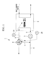
- Fig. 1 is a diagram showing, in outline, the configuration of a hot-water heat pump according to a first embodiment of the present invention.
- a hot-water heat pump 1 is provided with a hot-water-heat-pump main unit 2, a water-supply pump 3, and a three-way valve 4.
- the hot-water-heat-pump main unit 2 has a thermal output heat exchanger (not shown).
- the hot-water-heat-pump main unit 2 is typically a chiller in which the heat pump 1 can be operated, examples of which include an absorption chiller.
- the thermal output heat exchanger absorbs heat from the heat-source route, which is guided to the thermal output heat exchanger, and outputs heat.
- the thermal output level absorbed at the thermal output heat exchanger is controlled by a controller (not shown).
- the heat resulting from the absorption at the thermal output heat exchanger is outputted to the hot-water route via the thermal output heat exchanger.
- the heat outputted to the hot-water route is supplied to an external load (not shown), such as a fan coil, etc.
- a hot-water route (hereinafter, referred to as "upstream inlet-side hot-water route") 8, to which water is supplied from outside the hot-water heat pump 1, is pressurized by the water-supply pump 3.
- Pressurized water in a hot-water route (hereinafter, referred to as "inlet-side hot-water route") 5 is supplied to the thermal output heat exchanger.
- An inlet-side-hot-water-route temperature detector 20 that detects the temperature (inlet-side-hot-water-route temperature) of the inlet-side hot-water route 5 is provided between the water-supply pump 3 and the thermal output heat exchanger.
- the temperature of the upstream inlet-side hot-water route 8 and the initial temperature of the inlet-side hot-water route 5 are set to, for example, 30 °C.
- An outlet-side-hot-water-route temperature detector 21 is provided between a hot-water route (hereinafter, referred to as "outlet-side hot-water route") 6, which is outputted from the thermal output heat exchanger, and the three-way valve 4, described later.
- the temperature of the outlet-side hot-water route (outlet-side-hot-water-route temperature) detected by the outlet-side-hot-water-route temperature detector 21 is raised to, for example, 80 °C.
- the three-way valve 4 which is a flow-volume adjusting valve, is provided in the outlet-side hot-water route 6.
- a portion of the flow volume (hereinafter, referred to as "circulation hot-water route") 7 of the outlet-side hot-water route 6, whose temperature has been raised, is joined with the inlet-side hot-water route 5 by controlling the three-way valve 4 with the controller.
- the outlet-side hot-water route 6, whose temperature has been raised and which is not guided to the circulation hot-water route 7 via the three-way valve 4, is guided to outside the hot-water heat pump 1.
- the inlet-side hot-water route 5 that has reached the thermal output heat exchanger is outputted with heat, which is the heat absorbed from the heat-source route.
- FIG. 2 is a block diagram showing a method of controlling the hot-water heat pump according to the first embodiment.
- the three-way valve 4 is feedback controlled so that the temperature of the inlet-side hot-water route 5 reaches the inlet-side-hot-water-route target temperature.
- the flow volume of the circulation hot-water route 7 to be circulated from the three-way valve 4 to the thermal output heat exchanger can be increased, and, in the case in which the temperature of the inlet-side hot-water route 5 guided to the thermal output heat exchanger increases above the inlet-side-hot-water-route target temperature, the flow volume of the circulation hot-water route 7 to be circulated from the three-way valve 4 to the thermal output heat exchanger can be decreased.
- the thermal output level of the hot-water-heat-pump main unit 2 is feedback controlled so that the temperature of the outlet-side hot-water route 6 matches the outlet-side-hot-water-route target temperature.
- the thermal output level can be increased, and, in the case in which the temperature of the outlet-side hot-water route 6 increases over the outlet-side-hot-water-route target temperature, the thermal output level can be decreased. Accordingly, it is possible to control the heat that the inlet-side water-supply route 5 absorbes from the thermal output heat exchanger.
- the three-way valve 4 is feedback controlled on the basis of the temperature of the inlet-side hot-water route 5 detected by the inlet-side-hot-water-route temperature detector 20, and the thermal output level of the hot-water-heat-pump main unit 2 is feedback controlled on the basis of the temperature of the outlet hot-water route 6 detected by the outlet-side-hot-water-route temperature detector 21; therefore, it is possible to prevent interference between the control of the three-way valve 4 and the control of the thermal output level.
- the hot-water heat pump according to the first embodiment and the method of controlling the same afford the following effects and advantages.
- the inlet-side hot-water route (hot-water route) 5 directly absorbes heat from the thermal output heat exchanger without providing any additional device, etc. Accordingly, because the heat is directly outputted to the inlet-side hot-water route 5, the heating speed is increased for the outlet-side hot-water route (hot-water route outputted from thermal output heat exchanger) 6. Therefore, the heating time of the outlet-side hot-water route 6 can be reduced, while also reducing the installation cost of the hot-water heat pump 1 and the size of the hot-water heat pump 1.
- the hot-water heat pump 1 is provided with the controller (not shown) that controls the three-way valve so that the circulation hot-water route 7, which holds a portion of flow volume in the outlet-side hot-water route 6 whose temperature has been raised by receiving heat from the thermal output heat exchanger, forms a circulation path to the inlet-side hot-water route (hot-water route guided to the thermal output heat exchanger) 5 via the upstream inlet-side hot-water route 8.
- the temperature of the inlet-side hot-water route 5 guided to the thermal output heat exchanger can be controlled by controlling the size of openings of the three-way valve 4. Therefore, even in the case in which the heating speed of the outlet-side hot-water route 6 may be increased by directly absorbing heat from the thermal output heat exchanger, it is possible to control temperature fluctuations of the temperature of the outlet-side hot-water route 6.
- the hot-water heat pump 1 of the first embodiment is provided with the controller that controls the size of openings of the three-way valve 4 in accordance with the temperature of the inlet-side hot-water route 5. Accordingly, in the case in which the temperature of the inlet-side hot-water route 5 drops below the inlet-side-hot-water-route target temperature, the flow volume of the circulation hot-water route (hot-water route that forms the circulation path from the three-way valve 4 to the thermal output heat exchanger) 7 can be increased, and, in the case in which the temperature of the inlet-side hot-water route 5 increases above the inlet-side-hot-water-route target temperature, the flow volume of the circulation hot-water route 7 can be reduced. Therefore, it is possible to suppress temperature fluctuations in the inlet-side water-supply route 5, which is guided to the thermal output heat exchanger.
- the hot-water heat pump 1 of the first embodiment is provided with the controller that controls the thermal output level of the hot-water-heat-pump main unit 2 in accordance with the temperature of the outlet-side hot-water route 6.
- the thermal output level can be increased, and, in the case in which the temperature of the outlet-side hot-water route 6 increases above the outlet-side-hot-water-route target temperature, the thermal output level can be reduced. Accordingly, it is possible to control the heat that the inlet-side water-supply route 5 absorbes from the thermal output heat exchanger. Therefore, it is possible to suppress temperature fluctuations in the outlet-side hot-water route 6.
- the hot-water heat pump 1 of the first embodiment is provided with the controller with which the size of openings of the three-way valve 4 and the thermal output level are feedback controlled. Accordingly, even in the case in which the temperature of the inlet-side hot-water route 5 fluctuates, it is possible to maintain the temperature of the inlet-side hot-water route 5 at the inlet-side-hot-water-route target temperature.
- the controller with which the thermal output level is feedback controlled is also provided. Accordingly, it is possible to maintain the temperature of the outlet-side hot-water route 6 at the outlet-side-hot-water-route target temperature. Therefore, even in the case in which temperature changes in the outlet-side hot-water route 6 cannot be suppressed only by controlling the three-way valve 4, it is possible to suppress the temperature fluctuations in the outlet-side hot-water route 6.
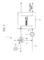
- the output-side-hot-water-route temperature detector 21 is provided in the outlet-side hot-water route 6 between the three-way valve 4 and the thermal output heat exchanger, the present invention is not limited thereto, and the output-side-hot-water-route temperature detector 21 may be provided in the outlet-side hot-water route downstream of the three-way valve 4, as shown in Fig. 3 .
- a hot-water heat pump of the second embodiment and a method of controlling the same differ from those of the first embodiment in that a temperature detector is provided in the upstream inlet hot-water route; that a flow-volume detector is provided at an inlet of the thermal output heat exchanger; and that feedforward control is additionally included for the three-way valve; however, other points are the same as those of the first embodiment. Therefore, the components and control method that are the same as those of the first embodiment are given the same reference signs, and the descriptions thereof will be omitted.
- Fig. 4 is a diagram showing, in outline, the configuration of the hot-water heat pump according to the second embodiment.
- the upstream inlet-side hot-water route 8 is provided with an upstream-inlet-side-hot-water-route temperature detector 22.
- the upstream-inlet-side-hot-water-route temperature detector 22 detects the temperature of the upstream inlet-side hot-water route 8 before joining the circulation hot-water route 7.
- an inlet-side flow-volume detector 23 is provided at the inlet of the thermal output heat exchanger.
- the inlet-side flow-volume detector 23 detects the flow volume of the inlet-side hot-water route 5 guided to the thermal output heat exchanger.
- Fig. 5 is a block diagram showing a method of controlling the hot-water heat pump according to the second embodiment.
- the three-way valve 4 is feedback controlled by the controller so that the temperature of the inlet-side hot-water route 5 reaches the inlet-side-hot-water-route target temperature.
- the controller determines the size of openings of the three-way valve 4 on the basis of a table related to the temperature of the upstream inlet-side hot-water route 8 detected by the upstream-inlet-side-hot-water-route temperature detector 22 and the flow volume of the inlet-side hot-water route 5 detected by the inlet-side flow-volume detector 23.
- the controller performs feedforward control for the size of openings of the three-way valve 4 determined from the table.
- the thermal output level from the hot-water-heat-pump main unit 2 is feedback controlled by the controller so that the temperature of the outlet-side hot-water route 6 matches the outlet-side-hot-water-route target temperature.
- the hot-water heat pump 1 of the second embodiment is provided with the controller, with which the size of openings of the three-way valve 4 is feedforward controlled in accordance with the temperature of the upstream inlet-side hot-water route (upstream-side hot-water route to which the hot-water route, whose temperature has been raised, is joined via the three-way valve 4) and the flow volume of the inlet-side hot-water route 5 at the inlet of the thermal output heat exchanger.
- the temperature of the inlet-side hot-water route 5 guided to the thermal output heat exchanger can be controlled by controlling the three-way valve 4. Therefore, it is possible to suppress temperature fluctuations in the outlet-side hot-water route 6.
- a hot-water heat pump of the third embodiment and a method of controlling the same differ from those of the first embodiment in that a temperature detector is provided in the upstream inlet-side hot-water route; that a flow-volume detector is provided at the inlet of the thermal output heat exchanger; that a temperature detector is provided in the heat-source route, which leads to the hot-water-heat-pump main unit; and that control of a temperature compensation term is additionally included for the three-way valve; however, other points are the same as those of the first embodiment. Therefore, the components and control method that are the same as those of the first embodiment are given the same reference signs, and the descriptions thereof will be omitted.
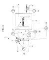
- Fig. 6 is a diagram showing, in outline, the configuration of the hot-water heat pump according to the third embodiment.
- the upstream inlet-side hot-water route 8 is provided with the upstream-inlet-side-hot-water-route temperature detector 22.
- the upstream-inlet-side-hot-water-route temperature detector 22 detects the temperature of the upstream inlet-side hot-water route 8.
- the inlet-side flow-volume detector 23 is provided at the inlet of the thermal output heat exchanger.
- the inlet-side flow-volume detector 23 detects the flow volume of the inlet-side hot-water route 5 guided to the thermal output heat exchanger.
- an inlet-side-heat-source-route temperature detector 24 is provided in the heat-source route (hereinafter, referred to as "inlet-side heat-source route") 9, which is guided to the thermal output heat exchanger.
- the inlet-side-heat-source-route temperature detector 24 detects the temperature of the inlet-side heat-source route 9.
- Fig. 7 is a block line diagram showing a method of controlling the hot-water heat pump according to the third embodiment.
- the three-way valve 4 is feedback controlled by the controller so that the temperature of the inlet-side hot-water route 5 reaches the inlet-side-hot-water-route target temperature.
- the controller determines the difference between the temperature of the inlet-side hot-water route 5 and the temperature of the outlet-side hot-water route 6.
- the controller inserts a first-order lag term. Subsequently, the controller controls the three-way valve 4 by including a temperature compensation term on the basis of the temperature of the outlet-side hot-water route 6 detected by the outlet-side-hot-water-route detector 21.
- the temperature compensation term performs temperature compensation so as to reduce a temperature difference between the temperature of the outlet-side hot-water route 6 and the outlet-side-hot-water-route target temperature.
- the controller determines the size of openings of the three-way valve 4 on the basis of a table related to the temperature of the upstream inlet-side hot-water route 8 detected by the upstream-inlet-side-hot-water-route temperature detector 22 and the flow volume of the inlet-side hot-water route 5 detected by the inlet-side flow-volume detector 23, and performs feedforward control for the size of openings of the three-way valve 4.
- the thermal output level from the hot-water-heat-pump main unit 2 is feedback controlled by the controller so that the temperature of the outlet-side hot-water route 6 matches the outlet-side-hot-water-route target temperature.
- the hot-water heat pump 1 of the third embodiment is provided with the controller that controls the size of openings of the three-way valve 4 on the basis of the temperature of the outlet-side hot-water route 6 by including the temperature compensation term that performs temperature compensation so as to reduce the temperature difference (difference) between the temperature of the outlet-side hot-water route 6 and the outlet-side-hot-water-route target temperature. Accordingly, even in the case in which the temperature of the outlet-side hot-water route 6 abruptly changes, the temperature of the inlet-side hot-water route 5 leading to the thermal output heat exchanger can be controlled by controlling the three-way valve 4. Therefore, it is possible to suppress the temperature fluctuations in the outlet-side hot-water route 6 outputted from the thermal output heat exchanger.
- the third embodiment has been described assuming that the three-way valve 4 is controlled on the basis of the temperature of the outlet-side hot-water route 6 detected by the outlet-side-hot-water-route temperature detector 21 by including the temperature compensation term, the present invention is not limited thereto.
- the three-way valve 4 may be controlled on the basis of the temperature of the inlet-side heat-source route 9 detected by the inlet-side-heat-source-route temperature detector 24 by including a temperature compensation term that performs temperature compensation so as to reduce the temperature difference between the temperature of the outlet-side hot-water route 6 and the outlet-side-hot-water-route target temperature.
- the three-way valve 4 is feedback controlled by the controller so that the temperature of the inlet-side hot-water route 5 reaches the inlet-side-hot-water-route target temperature. Furthermore, in the case in which the temperature of the inlet-side heat-source route 9 is higher or lower than the predetermined temperature, the controller inserts the first-order lag term. Subsequently, the controller controls the three-way valve 4 by including the temperature compensation term.
- the temperature compensation term performs temperature compensation so as to reduce the temperature difference between the temperature of the outlet-side hot-water route 6 and the outlet-side-hot-water-route target temperature, and it is determined on the basis of the temperature of the inlet-side heat-source route 9.
- the controller determines the size of openings of the three-way valve 4 on the basis of a table related to the temperature of the upstream inlet-side hot-water route 8 detected by the upstream-inlet-side-hot-water-route temperature detector 22 and the flow volume of the inlet-side hot-water route 5 detected by the inlet-side flow-volume detector 23 and performs feedforward control for the degree of opening of the three-way valve 4.
- the first-order lag term may be omitted. It is also permissible that the feedforward control is not included.
Landscapes
- Engineering & Computer Science (AREA)
- Physics & Mathematics (AREA)
- Thermal Sciences (AREA)
- Mechanical Engineering (AREA)
- General Engineering & Computer Science (AREA)
- Chemical & Material Sciences (AREA)
- Combustion & Propulsion (AREA)
- Heat-Pump Type And Storage Water Heaters (AREA)
- Steam Or Hot-Water Central Heating Systems (AREA)
Abstract
Description
- The present invention relates to a hot-water heat pump and a method of controlling the same and relates, in particular, to temperature control of a hot-water route that is guided from a hot-water heat pump.
- A hot-water route that supplies hot water is generally provided with a heat storage tank. In the hot water route, a portion of water stored in the heat storage tank absorbes heat from a thermal output heat exchanger provided in a hot-water-heat-pump main unit, thereby performing temperature control (for example, Patent Literature 1).
- In addition, the size of openings of control valves provided in a heat-source route and a coolant route, which lead to the hot-water heat pump, are controlled in accordance with the temperature of the hot-water route (for example,
Patent Literature 2 and Patent Literature 4). -
- {PTL 1} Japanese Unexamined Patent Application, Publication No.
Hei 7-225062 - {PTL 2} Publication of Japanese Patent, No.
2894602 - {PTL 3} Publication of Japanese Patent, No.
2842550 - {PTL 4} Publication of Japanese Patent, No.
3075944 - However, the invention disclosed in
Patent Literature 1 has a problem in that, because the heat storage tank is provided in the hot-water route, installation cost and installation space are required. The invention disclosed inPatent Literature 1 also has a problem in that, because water stored in the heat storage tank is circulated in the hot-water-heat-pump main unit to raise the temperature of water in the heat storage tank, raising the temperature is time consuming. - In addition, the inventions disclosed in
Patent Literatures 2 to 4 have a problem in that, because the temperature of the hot-water route is controlled by controlling flow volumes, etc. of the heat-source route and the coolant route, it is impossible to follow temperature changes when the temperature of the hot-water route is changed abruptly. - The present invention has been conceived in light of the above-described circumstances, and an object thereof is to provide a hot-water heat pump that is capable of reducing the installation cost and installation space and also capable of reducing the heating time for the hot-water route, and a method of controlling the same.
- In order to solve the above-described problems, the hot-water heat pump and the method of controlling the same according to the present invention employ the following solutions.
A hot-water heat pump according to a first aspect of the present invention is provided with a hot-water-heat-pump main unit that includes a thermal output heat exchanger that absorbs heat from a heat-source route and outputs heat; a hot-water route that receives the heat outputted from the thermal output heat exchanger; a three-way valve provided in the hot-water route; and a controller that controls the hot-water-heat-pump main unit and the three-way valve, wherein the controller controls the size of openings of the three-way valve so that a portion of the hot-water route outputted from the thermal output heat exchanger is guided to an upstream side of the thermal output heat exchanger. - A hot-water route that supplies hot water is conventionally provided with a heat storage tank. In the hot-water route, a portion of the water stored in this heat storage tank absorbes heat from a thermal output heat exchanger provided in the how-water-heat-pump main unit, thereby controlling the temperature thereof.
- With the first aspect of the present invention, the hot-water route directly absorbes heat from the thermal output heat exchanger without providing an additional device, etc. Accordingly, the heat is directly outputted to the hot-water route, thus increasing the heating speed for the hot-water route leading out of the thermal output heat exchanger. Therefore, the heating time of the hot-water route can be reduced, while also reducing the installation cost of the hot-water heat pump and the size of the hot-water heat pump.
- In addition, the controller is provided, which controls the three-way valve so that a portion of the hot-water route whose temperature has been raised by absorbing heat from the thermal output heat exchanger forms a circulation path to the hot-water route that leads to the thermal output heat exchanger. Accordingly, the temperature of the hot-water route leading to the thermal output heat exchanger can be controlled by controlling the size of openings of the three-way valve. Therefore, even in the case in which the heating speed of the hot-water route increases by directly absorbing heat from the thermal output heat exchanger, it is possible to control temperature fluctuations in the hot-water route outputted from the thermal output heat exchanger.
- The hot-water heat pump according to the first aspect of the present invention may be provided with an inlet-side-hot-water-route temperature detector provided in the hot-water route, which is guided to the thermal output heat exchanger; and an outlet-side-hot-water-route temperature detector provided in the hot-water route between the thermal output heat exchanger and the three-way valve, wherein the controller may control the size of openings of the three-way valve so that an inlet-side-hot-water-route temperature, which is detected by the inlet-side-hot-water-route temperature detector, reaches an inlet-side-hot-water-route target temperature.
- The controller that controls the size of openings of the three-way valve in accordance with the inlet-side-hot-water-route temperature is provided. Accordingly, in the case in which the inlet-side-hot-water-route temperature of the hot-water route, which is guided to the thermal output heat exchanger, drops below the inlet-side-hot-water-route target temperature, the flow volume of the hot-water route that forms the circulation path from the three-way valve to the thermal output heat exchanger can be increased, and, in the case in which the inlet-side-hot-water-route temperature of the water-supply route, which leads to the thermal output heat exchanger, increases above the inlet-side-hot-water-route target temperature, the flow volume of the hot-water route that forms the circulation path from the three-way valve to the thermal output heat exchanger can be reduced. Therefore, it is possible to suppress temperature fluctuations in the hot-water route guided to the thermal output heat exchanger.
- In the hot-water heat pump according to the first aspect of the present invention, the controller may control a thermal output level from the hot-water-heat-pump main unit so that an outlet-side-hot-water-route temperature, which is detected by the outlet-side-hot-water-route temperature detector, reaches an outlet-side-hot-water-route target temperature.
- The controller that controls the thermal output level of the hot-water-heat-pump main unit in accordance with the outlet-side-hot-water-route temperature is provided. By doing so, in the case in which the outlet-side-hot-water-route temperature drops below the outlet-side-hot-water-route target temperature, the thermal output level can be increased, and, in the case in which the outlet-side-hot-water-route temperature increases above the outlet-side-hot-water-route target temperature, the thermal output level can be reduced. Accordingly, it is possible to control the thermal output that the water-supply route receives from the thermal output heat exchanger. Therefore, it is possible to suppress temperature fluctuations in the hot-water route outputted from the thermal output heat exchanger.
- In the hot-water heat pump according to the first aspect of the present invention, the size of openings of the three-way valve and the thermal output level may be feedback controlled by the controller.
- The controller with which the size of openings of the three-way valve and the thermal output level are feedback controlled is provided. Accordingly, even in the case in which the inlet-side-hot-water-route temperature of the water-supply route guided to the thermal output heat exchanger fluctuates, it is possible to maintain the inlet-side-hot-water-route temperature at the inlet-side-hot-water-route target temperature. The controller with which the thermal output level is feedback controlled is also provided. Accordingly, it is possible to maintain the outlet-side-hot-water-route temperature of the water-supply route outputted from the thermal output heat exchanger at the outlet-side-hot-water-route target temperature. Therefore, even in the case in which temperature changes in the outlet-side-hot-water-route temperature cannot be suppressed only by controlling the three-way valve, it is possible to suppress the temperature fluctuations in the hot-water route outputted from the thermal output heat exchanger.
- The hot-water heat pump according to the first aspect of the present invention may be provided with an upstream-inlet-side-hot-water-route temperature detector provided in an upstream-side of the hot-water route with which the hot-water route guided from the three-way valve joins; and an inlet-side flow-volume detector that detects the flow volume of the hot-water route, which is guided to the thermal output heat exchanger, wherein the controller may perform feedforward control of the size of openings of the three-way valve by using the upstream-inlet-side-hot-water-route temperature detected by the upstream-inlet-side-hot-water-route temperature detector and inlet-side flow volume detected by the inlet-side flow-volume detector.
- The controller is provided, with which the size of openings of the three-way valve is feedforward controlled in accordance with the upstream-inlet-side-hot-water-route temperature of the upstream-side hot-water route to which the hot-water route, whose temperature has been raised, is joined via the three-way valve and the flow volume of the hot-water route on the inlet side of the thermal output heat exchanger to which the hot-water route, whose temperature has been raised, is joined. Accordingly, even in the case in which the temperature and the flow volume of the hot-water route abruptly change, it is possible to supply water, which has received the heat, to the thermal output heat exchanger by controlling the three-way valve. Therefore, it is possible to suppress temperature fluctuations in the hot-water route outputted from the thermal output heat exchanger.
- In the hot-water heat pump according to the first aspect of the present invention, the controller may control the size of openings of the three-way valve in the light of a temperature compensation term used for making the outlet-side-hot-water-route temperature approach the outlet-side-hot-water-route target temperature by using the outlet-side-hot-water-route temperature.
- The size of openings of the three-way valve is controlled on the basis of the outlet-side-hot-water-route temperature in the light of the temperature compensation term used for reducing the temperature difference between the outlet-side-hot-water-route temperature and the outlet-side-hot-water-route target temperature. Accordingly, even in the case in which the temperature of the hot-water route abruptly changes, it is possible to supply water, which has received the heat, to the thermal output heat exchanger by controlling the three-way valve. Therefore, it is possible to suppress the temperature fluctuations in the hot-water route outputted from the thermal output heat exchanger.
- In addition, a hot-water heat pump control method according to a second aspect of the present invention is a hot-water heat pump control method of controlling a hot-water-heat-pump main unit and a three-way valve of a hot-water heat pump provided with a hot-water heat pump main unit that includes a thermal output heat exchanger that absorbs heat from a heat-source route and outputs heat, a hot-water route that receives the heat outputted from the thermal output heat exchanger, and a three-way valve provided in the hot-water route, the method including controlling the degree of opening of the three-way valve so that a portion of the hot-water route outputted from the thermal output heat exchanger is guided to an upstream side of the thermal output heat exchanger.
- A hot-water route directly absorbes heat from a thermal output heat exchanger without providing any additional device, etc. Accordingly, the heat is directly outputted to the hot-water route, thus increasing the heating speed of the hot-water route outputted from the thermal output heat exchanger. Therefore, the heating time of the hot-water route can be reduced while reducing the installation cost of the hot-water heat pump and the size of the hot-water heat pump.
In addition, a controller is provided, which controls a three-way valve so that a portion of the hot-water route whose temperature has been raised by absorbing heat outputted from the thermal output heat exchanger forms a circulation path to the hot-water route that is guided to the thermal output heat exchanger. Accordingly, the temperature of the hot-water route outputted from the thermal output heat exchanger can be controlled by controlling the size of openings of the three-way valve. Therefore, even in the case in which the heating speed of the hot-water route increases by directly absorbing heat from the thermal output heat exchanger, it is possible to control temperature fluctuations in the hot-water route outputted from the thermal output heat exchanger. -
-
Fig. 1 is a diagram showing, in outline, the configuration of a hot-water heat pump according to a first embodiment of the present invention. -
Fig. 2 is a block diagram for a method of controlling the hot-water heat pump according to the first embodiment of the present invention. -
Fig. 3 is a diagram showing, in outline, the configuration of a modification of the hot-water heat pump according to the first embodiment of the present invention. -
Fig. 4 is a diagram showing, in outline, the configuration of a hot-water heat pump according to a second embodiment of the present invention. -
Fig. 5 is a block diagram for a method of controlling the hot-water heat pump according to the second embodiment of the present invention. -
Fig. 6 is a diagram showing, in outline, the configuration of a hot-water heat pump according to a third embodiment of the present invention. -
Fig. 7 is a block diagram for a method of controlling the hot-water heat pump according to the third embodiment of the present invention. -
Fig. 8 is a block diagram for a modification of a method of controlling the hot-water heat pump according to the third embodiment of the present invention. -
Fig. 1 is a diagram showing, in outline, the configuration of a hot-water heat pump according to a first embodiment of the present invention.
As shown inFig. 1 , a hot-water heat pump 1 is provided with a hot-water-heat-pumpmain unit 2, a water-supply pump 3, and a three-way valve 4. - The hot-water-heat-pump
main unit 2 has a thermal output heat exchanger (not shown). The hot-water-heat-pumpmain unit 2 is typically a chiller in which theheat pump 1 can be operated, examples of which include an absorption chiller. - The thermal output heat exchanger absorbs heat from the heat-source route, which is guided to the thermal output heat exchanger, and outputs heat. The thermal output level absorbed at the thermal output heat exchanger is controlled by a controller (not shown). The heat resulting from the absorption at the thermal output heat exchanger is outputted to the hot-water route via the thermal output heat exchanger. The heat outputted to the hot-water route is supplied to an external load (not shown), such as a fan coil, etc.
- A hot-water route (hereinafter, referred to as "upstream inlet-side hot-water route") 8, to which water is supplied from outside the hot-
water heat pump 1, is pressurized by the water-supply pump 3. Pressurized water in a hot-water route (hereinafter, referred to as "inlet-side hot-water route") 5 is supplied to the thermal output heat exchanger. An inlet-side-hot-water-route temperature detector 20 that detects the temperature (inlet-side-hot-water-route temperature) of the inlet-side hot-water route 5 is provided between the water-supply pump 3 and the thermal output heat exchanger. The temperature of the upstream inlet-side hot-water route 8 and the initial temperature of the inlet-side hot-water route 5 are set to, for example, 30 °C. - The inlet-side hot-
water route 5, which is guided to the thermal output heat exchanger, absorbes heat by means of the thermal output heat exchanger and is guided to the thermal output heat exchanger. An outlet-side-hot-water-route temperature detector 21 is provided between a hot-water route (hereinafter, referred to as "outlet-side hot-water route") 6, which is outputted from the thermal output heat exchanger, and the three-way valve 4, described later. By absorbing heat from the thermal output heat exchanger, the temperature of the outlet-side hot-water route (outlet-side-hot-water-route temperature) detected by the outlet-side-hot-water-route temperature detector 21 is raised to, for example, 80 °C. - The three-
way valve 4, which is a flow-volume adjusting valve, is provided in the outlet-side hot-water route 6. A portion of the flow volume (hereinafter, referred to as "circulation hot-water route") 7 of the outlet-side hot-water route 6, whose temperature has been raised, is joined with the inlet-side hot-water route 5 by controlling the three-way valve 4 with the controller. The outlet-side hot-water route 6, whose temperature has been raised and which is not guided to the circulation hot-water route 7 via the three-way valve 4, is guided to outside the hot-water heat pump 1. - Temperature of the circulation hot-
water route 7, which has joined with the upstream inlet-side hot-water route 8 via the three-way valve 4, becomes 75 °C by joining with the upstream inlet-side hot-water route 8 having a low temperature of, for example, 30 °C, and the circulation hot-water route 7 is guided to the thermal output heat exchanger via thewater supply pump 3. The inlet-side hot-water route 5 that has reached the thermal output heat exchanger is outputted with heat, which is the heat absorbed from the heat-source route. - Next, a method of controlling a hot-water heat pump according to the first embodiment of the present invention will be described.
Fig. 2 is a block diagram showing a method of controlling the hot-water heat pump according to the first embodiment.
In the case in which temperature of the inlet-side hot-water route 5 detected by the inlet-side-hot-water-route temperature detector 20 has not reached an inlet-side-hot-water-route target temperature, the three-way valve 4 is feedback controlled so that the temperature of the inlet-side hot-water route 5 reaches the inlet-side-hot-water-route target temperature. - By doing so, in the case in which the temperature of the inlet-side hot-
water route 5 guided to the thermal output heat exchanger drops below the inlet-side-hot-water-route target temperature, the flow volume of the circulation hot-water route 7 to be circulated from the three-way valve 4 to the thermal output heat exchanger can be increased, and, in the case in which the temperature of the inlet-side hot-water route 5 guided to the thermal output heat exchanger increases above the inlet-side-hot-water-route target temperature, the flow volume of the circulation hot-water route 7 to be circulated from the three-way valve 4 to the thermal output heat exchanger can be decreased. - Furthermore, in the case in which the temperature of the outlet-side hot-
water route 6 detected by the outlet-side-hot-water-route temperature detector 21 has not reached an outlet-side-hot-water-route target temperature, the thermal output level of the hot-water-heat-pumpmain unit 2 is feedback controlled so that the temperature of the outlet-side hot-water route 6 matches the outlet-side-hot-water-route target temperature. - By doing so, in the case in which the temperature of the outlet-side hot-
water route 6 drops below the outlet-side-hot-water-route target temperature, the thermal output level can be increased, and, in the case in which the temperature of the outlet-side hot-water route 6 increases over the outlet-side-hot-water-route target temperature, the thermal output level can be decreased. Accordingly, it is possible to control the heat that the inlet-side water-supply route 5 absorbes from the thermal output heat exchanger. - The three-
way valve 4 is feedback controlled on the basis of the temperature of the inlet-side hot-water route 5 detected by the inlet-side-hot-water-route temperature detector 20, and the thermal output level of the hot-water-heat-pumpmain unit 2 is feedback controlled on the basis of the temperature of the outlet hot-water route 6 detected by the outlet-side-hot-water-route temperature detector 21; therefore, it is possible to prevent interference between the control of the three-way valve 4 and the control of the thermal output level. - As has been described above, the hot-water heat pump according to the first embodiment and the method of controlling the same afford the following effects and advantages.
The inlet-side hot-water route (hot-water route) 5 directly absorbes heat from the thermal output heat exchanger without providing any additional device, etc. Accordingly, because the heat is directly outputted to the inlet-side hot-water route 5, the heating speed is increased for the outlet-side hot-water route (hot-water route outputted from thermal output heat exchanger) 6. Therefore, the heating time of the outlet-side hot-water route 6 can be reduced, while also reducing the installation cost of the hot-water heat pump 1 and the size of the hot-water heat pump 1. - In addition, the hot-
water heat pump 1 according to the first embodiment is provided with the controller (not shown) that controls the three-way valve so that the circulation hot-water route 7, which holds a portion of flow volume in the outlet-side hot-water route 6 whose temperature has been raised by receiving heat from the thermal output heat exchanger, forms a circulation path to the inlet-side hot-water route (hot-water route guided to the thermal output heat exchanger) 5 via the upstream inlet-side hot-water route 8. Accordingly, the temperature of the inlet-side hot-water route 5 guided to the thermal output heat exchanger can be controlled by controlling the size of openings of the three-way valve 4. Therefore, even in the case in which the heating speed of the outlet-side hot-water route 6 may be increased by directly absorbing heat from the thermal output heat exchanger, it is possible to control temperature fluctuations of the temperature of the outlet-side hot-water route 6. - In addition, the hot-
water heat pump 1 of the first embodiment is provided with the controller that controls the size of openings of the three-way valve 4 in accordance with the temperature of the inlet-side hot-water route 5. Accordingly, in the case in which the temperature of the inlet-side hot-water route 5 drops below the inlet-side-hot-water-route target temperature, the flow volume of the circulation hot-water route (hot-water route that forms the circulation path from the three-way valve 4 to the thermal output heat exchanger) 7 can be increased, and, in the case in which the temperature of the inlet-side hot-water route 5 increases above the inlet-side-hot-water-route target temperature, the flow volume of the circulation hot-water route 7 can be reduced. Therefore, it is possible to suppress temperature fluctuations in the inlet-side water-supply route 5, which is guided to the thermal output heat exchanger. - In addition, the hot-
water heat pump 1 of the first embodiment is provided with the controller that controls the thermal output level of the hot-water-heat-pumpmain unit 2 in accordance with the temperature of the outlet-side hot-water route 6. By doing so, in the case in which the temperature of the outlet-side hot-water route 6 drops below the outlet-side-hot-water-route target temperature, the thermal output level can be increased, and, in the case in which the temperature of the outlet-side hot-water route 6 increases above the outlet-side-hot-water-route target temperature, the thermal output level can be reduced. Accordingly, it is possible to control the heat that the inlet-side water-supply route 5 absorbes from the thermal output heat exchanger. Therefore, it is possible to suppress temperature fluctuations in the outlet-side hot-water route 6. - In addition, the hot-
water heat pump 1 of the first embodiment is provided with the controller with which the size of openings of the three-way valve 4 and the thermal output level are feedback controlled. Accordingly, even in the case in which the temperature of the inlet-side hot-water route 5 fluctuates, it is possible to maintain the temperature of the inlet-side hot-water route 5 at the inlet-side-hot-water-route target temperature. The controller with which the thermal output level is feedback controlled is also provided. Accordingly, it is possible to maintain the temperature of the outlet-side hot-water route 6 at the outlet-side-hot-water-route target temperature. Therefore, even in the case in which temperature changes in the outlet-side hot-water route 6 cannot be suppressed only by controlling the three-way valve 4, it is possible to suppress the temperature fluctuations in the outlet-side hot-water route 6. - Note that, although the first embodiment has been described assuming that the output-side-hot-water-
route temperature detector 21 is provided in the outlet-side hot-water route 6 between the three-way valve 4 and the thermal output heat exchanger, the present invention is not limited thereto, and the output-side-hot-water-route temperature detector 21 may be provided in the outlet-side hot-water route downstream of the three-way valve 4, as shown inFig. 3 . - A second embodiment of the present invention will be described below. A hot-water heat pump of the second embodiment and a method of controlling the same differ from those of the first embodiment in that a temperature detector is provided in the upstream inlet hot-water route; that a flow-volume detector is provided at an inlet of the thermal output heat exchanger; and that feedforward control is additionally included for the three-way valve; however, other points are the same as those of the first embodiment. Therefore, the components and control method that are the same as those of the first embodiment are given the same reference signs, and the descriptions thereof will be omitted.
-
Fig. 4 is a diagram showing, in outline, the configuration of the hot-water heat pump according to the second embodiment.
The upstream inlet-side hot-water route 8 is provided with an upstream-inlet-side-hot-water-route temperature detector 22. The upstream-inlet-side-hot-water-route temperature detector 22 detects the temperature of the upstream inlet-side hot-water route 8 before joining the circulation hot-water route 7. - In addition, an inlet-side flow-
volume detector 23 is provided at the inlet of the thermal output heat exchanger. The inlet-side flow-volume detector 23 detects the flow volume of the inlet-side hot-water route 5 guided to the thermal output heat exchanger. - Next, a method of controlling a hot-water heat pump according to the second embodiment of the present invention will be described.
Fig. 5 is a block diagram showing a method of controlling the hot-water heat pump according to the second embodiment.
In the case in which the temperature of the inlet-side hot-water route 5 has not reached the inlet-side-hot-water-route target temperature, the three-way valve 4 is feedback controlled by the controller so that the temperature of the inlet-side hot-water route 5 reaches the inlet-side-hot-water-route target temperature.
Subsequently, the controller determines the size of openings of the three-way valve 4 on the basis of a table related to the temperature of the upstream inlet-side hot-water route 8 detected by the upstream-inlet-side-hot-water-route temperature detector 22 and the flow volume of the inlet-side hot-water route 5 detected by the inlet-side flow-volume detector 23. - The controller performs feedforward control for the size of openings of the three-
way valve 4 determined from the table.
On the other hand, in the case in which the temperature of the outlet-side hot-water route 6 has not reached the outlet-side-hot-water-route target temperature, the thermal output level from the hot-water-heat-pumpmain unit 2 is feedback controlled by the controller so that the temperature of the outlet-side hot-water route 6 matches the outlet-side-hot-water-route target temperature. - As has been described above, the hot-water heat pump according to the second embodiment and the method of controlling the same afford the following effects and advantages.
The hot-water heat pump 1 of the second embodiment is provided with the controller, with which the size of openings of the three-way valve 4 is feedforward controlled in accordance with the temperature of the upstream inlet-side hot-water route (upstream-side hot-water route to which the hot-water route, whose temperature has been raised, is joined via the three-way valve 4) and the flow volume of the inlet-side hot-water route 5 at the inlet of the thermal output heat exchanger. Accordingly, even in the case in which the temperature and the flow volume of the upstream inlet-side hot-water route (hot-water route) 8 abruptly change, the temperature of the inlet-side hot-water route 5 guided to the thermal output heat exchanger can be controlled by controlling the three-way valve 4. Therefore, it is possible to suppress temperature fluctuations in the outlet-side hot-water route 6. - A third embodiment of the present invention will be described below. A hot-water heat pump of the third embodiment and a method of controlling the same differ from those of the first embodiment in that a temperature detector is provided in the upstream inlet-side hot-water route; that a flow-volume detector is provided at the inlet of the thermal output heat exchanger; that a temperature detector is provided in the heat-source route, which leads to the hot-water-heat-pump main unit; and that control of a temperature compensation term is additionally included for the three-way valve; however, other points are the same as those of the first embodiment. Therefore, the components and control method that are the same as those of the first embodiment are given the same reference signs, and the descriptions thereof will be omitted.
-
Fig. 6 is a diagram showing, in outline, the configuration of the hot-water heat pump according to the third embodiment.
The upstream inlet-side hot-water route 8 is provided with the upstream-inlet-side-hot-water-route temperature detector 22. The upstream-inlet-side-hot-water-route temperature detector 22 detects the temperature of the upstream inlet-side hot-water route 8. - The inlet-side flow-
volume detector 23 is provided at the inlet of the thermal output heat exchanger. The inlet-side flow-volume detector 23 detects the flow volume of the inlet-side hot-water route 5 guided to the thermal output heat exchanger. - In addition, an inlet-side-heat-source-
route temperature detector 24 is provided in the heat-source route (hereinafter, referred to as "inlet-side heat-source route") 9, which is guided to the thermal output heat exchanger. The inlet-side-heat-source-route temperature detector 24 detects the temperature of the inlet-side heat-source route 9. - Next, a method of controlling the hot-water heat pump according to the third embodiment of the present invention will be described.
Fig. 7 is a block line diagram showing a method of controlling the hot-water heat pump according to the third embodiment.
In the case in which the temperature of the inlet-side hot-water route 5 has not reached the inlet-side-hot-water-route target temperature, the three-way valve 4 is feedback controlled by the controller so that the temperature of the inlet-side hot-water route 5 reaches the inlet-side-hot-water-route target temperature.
Furthermore, the controller determines the difference between the temperature of the inlet-side hot-water route 5 and the temperature of the outlet-side hot-water route 6. In the case in which this difference is larger than a predetermined difference, the controller inserts a first-order lag term. Subsequently, the controller controls the three-way valve 4 by including a temperature compensation term on the basis of the temperature of the outlet-side hot-water route 6 detected by the outlet-side-hot-water-route detector 21. The temperature compensation term performs temperature compensation so as to reduce a temperature difference between the temperature of the outlet-side hot-water route 6 and the outlet-side-hot-water-route target temperature. - Additionally, the controller determines the size of openings of the three-
way valve 4 on the basis of a table related to the temperature of the upstream inlet-side hot-water route 8 detected by the upstream-inlet-side-hot-water-route temperature detector 22 and the flow volume of the inlet-side hot-water route 5 detected by the inlet-side flow-volume detector 23, and performs feedforward control for the size of openings of the three-way valve 4. - On the other hand, in the case in which the temperature of the outlet-side hot-
water route 6 has not reached the outlet-side-hot-water-route target temperature, the thermal output level from the hot-water-heat-pumpmain unit 2 is feedback controlled by the controller so that the temperature of the outlet-side hot-water route 6 matches the outlet-side-hot-water-route target temperature. - As has been descried above, the hot-water heat pump according to the third embodiment and the method of controlling the same afford the following effects and advantages.
The hot-water heat pump 1 of the third embodiment is provided with the controller that controls the size of openings of the three-way valve 4 on the basis of the temperature of the outlet-side hot-water route 6 by including the temperature compensation term that performs temperature compensation so as to reduce the temperature difference (difference) between the temperature of the outlet-side hot-water route 6 and the outlet-side-hot-water-route target temperature. Accordingly, even in the case in which the temperature of the outlet-side hot-water route 6 abruptly changes, the temperature of the inlet-side hot-water route 5 leading to the thermal output heat exchanger can be controlled by controlling the three-way valve 4. Therefore, it is possible to suppress the temperature fluctuations in the outlet-side hot-water route 6 outputted from the thermal output heat exchanger. - Note that, although the third embodiment has been described assuming that the three-
way valve 4 is controlled on the basis of the temperature of the outlet-side hot-water route 6 detected by the outlet-side-hot-water-route temperature detector 21 by including the temperature compensation term, the present invention is not limited thereto. For example, the three-way valve 4 may be controlled on the basis of the temperature of the inlet-side heat-source route 9 detected by the inlet-side-heat-source-route temperature detector 24 by including a temperature compensation term that performs temperature compensation so as to reduce the temperature difference between the temperature of the outlet-side hot-water route 6 and the outlet-side-hot-water-route target temperature.
Fig. 8 shows, as a reference example, a block line diagram for a method of controlling a hot-water heat pump for this case.
In the case in which the temperature of the inlet-side hot-water route 5 has not reached the inlet-side-hot-water-route target temperature, the three-way valve 4 is feedback controlled by the controller so that the temperature of the inlet-side hot-water route 5 reaches the inlet-side-hot-water-route target temperature.
Furthermore, in the case in which the temperature of the inlet-side heat-source route 9 is higher or lower than the predetermined temperature, the controller inserts the first-order lag term. Subsequently, the controller controls the three-way valve 4 by including the temperature compensation term. The temperature compensation term performs temperature compensation so as to reduce the temperature difference between the temperature of the outlet-side hot-water route 6 and the outlet-side-hot-water-route target temperature, and it is determined on the basis of the temperature of the inlet-side heat-source route 9. - In addition, the controller determines the size of openings of the three-
way valve 4 on the basis of a table related to the temperature of the upstream inlet-side hot-water route 8 detected by the upstream-inlet-side-hot-water-route temperature detector 22 and the flow volume of the inlet-side hot-water route 5 detected by the inlet-side flow-volume detector 23 and performs feedforward control for the degree of opening of the three-way valve 4. - Additionally, although this embodiment and the modification have been described assuming that the three-
way valve 4 is controlled by inserting the first-order lag term, the first-order lag term may be omitted. It is also permissible that the feedforward control is not included. -
- 1
- hot-water heat pump
- 2
- hot-water-heat-pump main unit
- 4
- three-way valve
- 5
- hot-water route (inlet-side hot-water route)
- 6
- hot-water route (outlet-side hot-water route)
Claims (7)
- A hot-water heat pump comprising:a hot-water-heat-pump main unit that includes a thermal output heat exchanger that absorbs heat from a heat-source route and outputs heat;a hot-water route that receives the heat outputted from the thermal output heat exchanger;a three-way valve provided in the hot-water route; anda controller that controls the hot-water-heat-pump main unit and the three-way valve,wherein the controller controls the size of openings of the three-way valve so that a portion of the hot-water route outputted from the thermal output heat exchanger is guided to an upstream side of the thermal output heat exchanger.
- A hot-water heat pump according to Claim 1, further comprising:an inlet-side-hot-water-route temperature detector provided in the hot-water route, which is guided to the thermal output heat exchanger; andan outlet-side-hot-water-route temperature detector provided in the hot-water route between the thermal output heat exchanger and the three-way valve,wherein the controller controls the size of openings of the three-way valve so that an inlet-side-hot-water-route temperature, which is detected by the inlet-side-hot-water-route temperature detector, reaches an inlet-side-hot-water-route target temperature.
- A hot-water heat pump according to Claim 1 or 2, wherein the controller controls a thermal output level of the hot-water-heat-pump main unit so that an outlet-side-hot-water-route temperature, which is detected by the outlet-side-hot-water-route temperature detector, reaches an outlet-side-hot-water-route target temperature.
- A hot-water heat pump according to any one of Claims 1 to 3, wherein the size of openings of the three-way valve and the thermal output level are feedback controlled by the controller.
- A hot-water heat pump according to any one of Claims 1 to 4, further comprising:an upstream-inlet-side-hot-water-route temperature detector provided in an upstream-side of the hot-water route with which the hot-water route guided from the three-way valve joins; andan inlet-side flow-volume detector that detects the flow volume of the hot-water route, which is guided to the thermal output heat exchanger,wherein the controller performs feedforward control of the size of openings of the three-way valve by using the upstream-inlet-side-hot-water-route temperature detected by the upstream-inlet-side-hot-water-route temperature detector and inlet-side flow volume detected by the inlet-side flow-volume detector.
- A hot-water heat pump according to any one of Claims 1 to 5, wherein the controller controls the size of openings of the three-way valve in the light of a temperature compensation term used for making the outlet-side-hot-water-route temperature approach the outlet-side-hot-water-route target temperature by using the outlet-side-hot-water-route temperature.
- A hot-water heat pump control method of controlling a hot-water-heat-pump main unit and a three-way valve of a hot-water heat pump provided with a hot-water heat pump main unit that includes a thermal output heat exchanger that absorbs heat from a heat-source route and outputs heat, a hot-water route that receives the heat outputted from the thermal output heat exchanger, and a three-way valve provided in the hot-water route,
the method comprising:controlling the size of openings of the three-way valve so that a portion of the hot-water route outputted from the thermal output heat exchanger is guided to an upstream side of the thermal output heat exchanger.
Applications Claiming Priority (2)
| Application Number | Priority Date | Filing Date | Title |
|---|---|---|---|
| JP2010048886A JP5729910B2 (en) | 2010-03-05 | 2010-03-05 | Hot water heat pump and control method thereof |
| PCT/JP2011/053768 WO2011108392A1 (en) | 2010-03-05 | 2011-02-22 | Hot water heat pump and method for controlling same |
Publications (2)
| Publication Number | Publication Date |
|---|---|
| EP2543935A1 true EP2543935A1 (en) | 2013-01-09 |
| EP2543935A4 EP2543935A4 (en) | 2013-11-20 |
Family
ID=44542048
Family Applications (1)
| Application Number | Title | Priority Date | Filing Date |
|---|---|---|---|
| EP11750504.0A Withdrawn EP2543935A4 (en) | 2010-03-05 | 2011-02-22 | Hot water heat pump and method for controlling same |
Country Status (6)
| Country | Link |
|---|---|
| US (1) | US9664415B2 (en) |
| EP (1) | EP2543935A4 (en) |
| JP (1) | JP5729910B2 (en) |
| KR (2) | KR20120104372A (en) |
| CN (1) | CN102725591B (en) |
| WO (1) | WO2011108392A1 (en) |
Families Citing this family (17)
| Publication number | Priority date | Publication date | Assignee | Title |
|---|---|---|---|---|
| JP5729910B2 (en) * | 2010-03-05 | 2015-06-03 | 三菱重工業株式会社 | Hot water heat pump and control method thereof |
| EP2413048B1 (en) * | 2010-07-30 | 2013-06-05 | Grundfos Management A/S | Domestic water heating unit |
| JP5536013B2 (en) * | 2011-11-11 | 2014-07-02 | 三菱重工業株式会社 | Hot water heating system, control device and control method |
| WO2014075303A1 (en) * | 2012-11-16 | 2014-05-22 | 格兰富控股联合股份公司 | Thermal equilibrium set and control method and control apparatus thereof |
| DE102012024347A1 (en) * | 2012-12-13 | 2014-06-18 | Robert Bosch Gmbh | Heating device and method for its operation |
| KR101549657B1 (en) * | 2013-11-08 | 2015-09-03 | 한국에너지기술연구원 | System and method for controlling of heat exchange between district heating networks |
| FR3046665A1 (en) * | 2016-01-08 | 2017-07-14 | Elax Dev | CONTROL UNIT FOR CONTROLLING A TEMPERATURE OF A FIRST HEAT PUMP INTO A WATER / WATER HEAT PUMP |
| KR101950888B1 (en) * | 2017-02-02 | 2019-02-21 | 김인수 | Boiler |
| CN107131651B (en) * | 2017-04-17 | 2020-06-30 | 广东芬尼克兹节能设备有限公司 | Device and method for stably adjusting water temperature |
| CN107504548A (en) * | 2017-09-18 | 2017-12-22 | 江苏中圣管道工程技术有限公司 | A kind of steam-water mixing central heating system |
| JP6894814B2 (en) * | 2017-09-21 | 2021-06-30 | 日立建機株式会社 | Hybrid work machine |
| CN109442602B (en) * | 2018-08-27 | 2021-04-13 | 广东芬尼克兹节能设备有限公司 | Waterway control system of heat pump unit and control method thereof |
| CN110513930B (en) * | 2019-09-05 | 2021-07-13 | 四川长虹空调有限公司 | Loading and unloading control method for variable-frequency compressor of air source heat pump unit |
| US11313588B2 (en) * | 2019-09-20 | 2022-04-26 | Camus Hydronics Ltd. | System and method for controlling water heater output temperature |
| CN110726245B (en) * | 2019-10-08 | 2021-05-25 | 广东纽恩泰新能源科技发展有限公司 | Household variable-frequency direct-heating air energy heat pump water heater |
| CN110953688A (en) * | 2019-12-30 | 2020-04-03 | 格力电器(武汉)有限公司 | Water supply circulating system and water tank waterway testing method |
| DE102023212531A1 (en) | 2023-12-12 | 2025-06-12 | Robert Bosch Gesellschaft mit beschränkter Haftung | Process and heat pump system |
Family Cites Families (96)
| Publication number | Priority date | Publication date | Assignee | Title |
|---|---|---|---|---|
| US1611764A (en) * | 1921-07-22 | 1926-12-21 | Louis R Mendelson | Indirect water heater |
| US2619326A (en) * | 1949-11-29 | 1952-11-25 | Gen Electric | Fluid heating system, including a heat pump |
| US3490517A (en) * | 1965-08-10 | 1970-01-20 | Nat Service Ind Inc | Dynamically integrated comfort conditioning system |
| US3403723A (en) * | 1965-08-10 | 1968-10-01 | Lithonia Lighting Inc | Dynamically integrated comfort conditioning system |
| US3658244A (en) * | 1970-03-20 | 1972-04-25 | Ranco Inc | Air tempering system |
| SE389188B (en) * | 1973-12-20 | 1976-10-25 | Projectus Ind Produkter Ab | PROCEDURE AND DEVICE FOR HEATING FLUID IN DIFFERENT CIRCUITS FOR DIFFERENT FORMS BY MEASUREMENT OF A HEAT PUMP, INCLUDING A REFRIGERATOR CIRCUIT WITH AN EXPANSION VALVE, AN EVAPORATOR, A COMPRESSOR AND A CONDENSER APPLIANCE |
| US4257556A (en) * | 1975-05-07 | 1981-03-24 | Skala Stephen F | Fluid heat transfer system |
| DE2721301A1 (en) * | 1977-05-12 | 1978-11-23 | Geb Entian Anneliese Ohms | Combined central heating system for buildings - has heat recovery heat exchanger with series connected cycle improving efficiency |
| CH644460A5 (en) * | 1980-02-27 | 1984-07-31 | Aquametro Ag | SYSTEM FOR TRANSPORTING HEAT BY MEANS OF A FLUID. |
| DE3014029A1 (en) * | 1980-04-11 | 1981-10-22 | Rheinisch-Westfälisches Elektrizitätswerk AG, 4300 Essen | Heat pump for heating system - uses heating medium to cool engine driving compressor |
| JPS5721727A (en) * | 1980-07-11 | 1982-02-04 | Hitachi Ltd | Heat pump type heater |
| JPS5721726A (en) * | 1980-07-11 | 1982-02-04 | Hitachi Ltd | Heat pump type heater |
| US4341263A (en) * | 1980-11-11 | 1982-07-27 | Morteza Arbabian | Waste water heat recovery apparatus |
| GB2090023B (en) * | 1980-12-22 | 1984-04-18 | British Gas Corp | Central heating control system |
| DE3105373A1 (en) * | 1981-02-13 | 1982-11-11 | Siemens AG, 1000 Berlin und 8000 München | HEATING SYSTEM |
| DE3302065A1 (en) * | 1982-02-06 | 1983-08-18 | Joh. Vaillant Gmbh U. Co, 5630 Remscheid | Sorption heat pump |
| DE3207435A1 (en) * | 1982-02-06 | 1983-09-08 | Joh. Vaillant Gmbh U. Co, 5630 Remscheid | Control and regulating device for a suction heat pump |
| JPS6029863B2 (en) * | 1982-12-10 | 1985-07-12 | 工業技術院長 | solar heat utilization plant |
| US4498622A (en) * | 1983-05-23 | 1985-02-12 | Borg-Warner Corporation | Quick recovery heat pump water heater |
| US4522253A (en) * | 1983-08-10 | 1985-06-11 | The Bennett Levin Associates, Inc. | Water-source heat pump system |
| CA1214336A (en) * | 1983-10-11 | 1986-11-25 | Sven G. Oskarsson | Heat pump system |
| JPS61125540A (en) * | 1984-11-21 | 1986-06-13 | Fuji Heavy Ind Ltd | Heat pump device for hot-water supplying |
| JPS623443A (en) | 1985-06-28 | 1987-01-09 | Nippon Telegr & Teleph Corp <Ntt> | Flexible optical disc and its manufacture |
| DE3608867A1 (en) * | 1986-03-17 | 1987-09-24 | Stiebel Eltron Gmbh & Co Kg | Charging control of a hot-water storage tank heated by a heat pump |
| JPS632357A (en) * | 1986-06-19 | 1988-01-07 | インタ−ナショナル ビジネス マシ−ンズ コ−ポレ−ション | Heatsink structure |
| JPS6332224A (en) * | 1986-07-25 | 1988-02-10 | Takuma Co Ltd | Heat supply system |
| US4824740A (en) * | 1987-06-15 | 1989-04-25 | International Fuel Cell Corporation | Fuel cell stack cooling system |
| GB8919654D0 (en) * | 1989-08-31 | 1989-10-11 | Worcester Heat Systems Ltd | Improvements in or relating to water heating systems |
| US5115491A (en) * | 1990-12-17 | 1992-05-19 | Maier Perlman | Tempering system for storage tank water heaters utilizing inlet and outlet heat exchanger |
| US5366151A (en) * | 1993-12-27 | 1994-11-22 | Ford Motor Company | Hybrid vehicle fuel vapor management apparatus |
| JPH07225062A (en) | 1994-02-16 | 1995-08-22 | Hitachi Ltd | Absorption heat pump |
| JP2842550B2 (en) | 1994-11-25 | 1999-01-06 | 東京瓦斯株式会社 | Absorption chiller / heater |
| JP3075944B2 (en) | 1994-11-29 | 2000-08-14 | 三洋電機株式会社 | Absorption chiller / heater |
| DE19509419A1 (en) * | 1995-03-16 | 1996-09-19 | Klaus Grubert | Demand-dependent circulation pump control for central hot water supply |
| US5613372A (en) * | 1995-05-26 | 1997-03-25 | Dumont Management, Inc. | Heat pump system dehumidifier with secondary water loop |
| JP3735891B2 (en) * | 1995-05-26 | 2006-01-18 | 株式会社ノーリツ | 1 can, 2 waterway bath equipment |
| JP2894602B2 (en) | 1995-10-02 | 1999-05-24 | 東京瓦斯株式会社 | Absorption chiller / heater and control method thereof |
| US5727396A (en) * | 1995-12-15 | 1998-03-17 | Gas Research Institute | Method and apparatus for cooling a prime mover for a gas-engine driven heat pump |
| US5947373A (en) * | 1996-02-09 | 1999-09-07 | Sanyo Electric Co., Ltd. | Refrigerant circuit with fluid heated refrigerant |
| DE19620399A1 (en) * | 1996-05-21 | 1997-11-27 | Stiebel Eltron Gmbh & Co Kg | Method of using a heating system |
| JP3632357B2 (en) | 1997-03-17 | 2005-03-23 | 松下電器産業株式会社 | Heat pump bath water supply system |
| US7147071B2 (en) * | 2004-02-04 | 2006-12-12 | Battelle Energy Alliance, Llc | Thermal management systems and methods |
| US5918805A (en) * | 1998-01-14 | 1999-07-06 | Yankee Scientific, Inc. | Self-powered space heating system |
| US6109346A (en) * | 1998-01-20 | 2000-08-29 | Hill; Gary G. | Waste heat auxiliary tank system method and apparatus |
| CN2392132Y (en) * | 1999-09-23 | 2000-08-16 | 杨民 | Consatant temp. drain device for water heater |
| US6560978B2 (en) * | 2000-12-29 | 2003-05-13 | Thermo King Corporation | Transport temperature control system having an increased heating capacity and a method of providing the same |
| JP3969154B2 (en) * | 2001-08-24 | 2007-09-05 | 株式会社デンソー | Hot water storage water heater |
| JP2003106653A (en) * | 2001-09-28 | 2003-04-09 | Kansai Electric Power Co Inc:The | Heat pump water heater |
| JP3742356B2 (en) * | 2002-03-20 | 2006-02-01 | 株式会社日立製作所 | Heat pump water heater |
| FR2847972B1 (en) * | 2002-11-29 | 2005-03-04 | Realisation Mecaniques Engenee | HEAT EXCHANGER AND DEVICE FOR PRODUCING HOT WATER |
| JP2004268752A (en) * | 2003-03-10 | 2004-09-30 | Denso Corp | Thermal management system |
| JP3956925B2 (en) * | 2003-09-24 | 2007-08-08 | 松下電器産業株式会社 | Water heater |
| JP2005121283A (en) * | 2003-10-16 | 2005-05-12 | Matsushita Electric Ind Co Ltd | Heat pump water heater |
| JP4304601B2 (en) * | 2004-01-20 | 2009-07-29 | 株式会社ノーリツ | Storage water heater and cogeneration system |
| US6862894B1 (en) * | 2004-02-04 | 2005-03-08 | Donald R. Miles | Adaptive auxiliary condensing device and method |
| DE102004018034B4 (en) * | 2004-04-14 | 2014-07-24 | Stiebel Eltron Gmbh & Co. Kg | Method for switching on a heat pump in connection with a hot water storage tank for heat pumps |
| JP4279725B2 (en) * | 2004-06-03 | 2009-06-17 | 関西電力株式会社 | Heat pump water heater / heater |
| JP2006083720A (en) * | 2004-09-14 | 2006-03-30 | Honda Motor Co Ltd | Cogeneration equipment |
| US8567689B2 (en) * | 2004-09-17 | 2013-10-29 | Carrier Corporation | Sanitary operator of a hot water heat pump |
| JP2006177625A (en) * | 2004-12-24 | 2006-07-06 | Corona Corp | Hot water storing type water heater bath apparatus |
| JP3864981B2 (en) * | 2005-04-21 | 2007-01-10 | 松下電器産業株式会社 | Heat pump water heater |
| WO2007004460A1 (en) * | 2005-06-30 | 2007-01-11 | Toshiba Carrier Corporation | Heat pump hotwater supply device |
| GB0522307D0 (en) * | 2005-11-01 | 2005-12-07 | Zenex Technologies Ltd | A burner and heat exchanger combination, and a boiler including such a burner and heat exchanger combination |
| JP3966889B2 (en) * | 2005-12-28 | 2007-08-29 | シャープ株式会社 | Heat pump water heater |
| DE102006017198A1 (en) * | 2006-04-12 | 2007-10-25 | Joachim Kiefer | Heat storage system |
| JP4857903B2 (en) * | 2006-05-17 | 2012-01-18 | ダイキン工業株式会社 | Water heater |
| KR101270615B1 (en) * | 2006-07-25 | 2013-06-07 | 엘지전자 주식회사 | Co-generation and Control method of the same |
| KR101270616B1 (en) * | 2006-07-27 | 2013-06-07 | 엘지전자 주식회사 | Cogeneration |
| WO2008025850A2 (en) * | 2006-08-31 | 2008-03-06 | Colipu A/S | An energy system with a heat pump |
| KR100805551B1 (en) * | 2006-10-17 | 2008-02-20 | 주식회사 경동나비엔 | How to prevent condensation of boiler flue flue |
| JP4767207B2 (en) * | 2007-03-29 | 2011-09-07 | 三菱電機株式会社 | Water heater |
| US8955763B2 (en) * | 2007-10-04 | 2015-02-17 | Consolidated Edison Company Of New York, Inc. | Building heating system and method of operation |
| EP2184563A4 (en) * | 2008-02-04 | 2016-02-17 | Mitsubishi Electric Corp | COMPLEX SYSTEM OF AIR CONDITIONING AND WATER HEATER |
| JP4859874B2 (en) * | 2008-05-12 | 2012-01-25 | 三菱重工業株式会社 | Rotational speed control device for cooling seawater transfer pump |
| JP2009281650A (en) * | 2008-05-21 | 2009-12-03 | Daikin Ind Ltd | Heating system |
| JP4949325B2 (en) * | 2008-06-03 | 2012-06-06 | 本田技研工業株式会社 | Cogeneration equipment |
| JP5171410B2 (en) * | 2008-06-11 | 2013-03-27 | リンナイ株式会社 | Hot water supply system |
| KR101329509B1 (en) * | 2008-08-04 | 2013-11-13 | 엘지전자 주식회사 | Hot water circulation system associated with heat pump and method for controlling the same |
| US8657207B2 (en) * | 2008-08-26 | 2014-02-25 | Lg Electronics Inc. | Hot water circulation system associated with heat pump and method for controlling the same |
| JP5713536B2 (en) * | 2009-01-05 | 2015-05-07 | 三菱電機株式会社 | Heat pump water heater |
| AU2010207400B2 (en) * | 2009-01-20 | 2013-01-31 | Daikin Industries, Ltd. | Water heat exchanger and hot water heat source apparatus |
| JP2010196953A (en) * | 2009-02-24 | 2010-09-09 | Daikin Ind Ltd | Heat pump system |
| JP5551882B2 (en) * | 2009-02-24 | 2014-07-16 | ダイキン工業株式会社 | Heat pump system |
| JP5200996B2 (en) * | 2009-02-24 | 2013-06-05 | ダイキン工業株式会社 | Heat pump system |
| JP2010196946A (en) * | 2009-02-24 | 2010-09-09 | Daikin Ind Ltd | Heat pump system |
| JP5316074B2 (en) * | 2009-02-24 | 2013-10-16 | ダイキン工業株式会社 | Heat pump system |
| US20120018129A1 (en) * | 2009-03-26 | 2012-01-26 | Mitsubishi Electric Corporation | Temperature adjusting apparatus, fluid supply system, heating system, installation method of temperature adjusting apparatus, and fluid supply method |
| JP5470374B2 (en) * | 2009-04-13 | 2014-04-16 | パナソニック株式会社 | Heat pump heating system |
| FR2947896B1 (en) * | 2009-07-07 | 2016-07-01 | Bosch Gmbh Robert | INSTALLATION FOR HEATING AND / OR SUPPLYING HOT WATER |
| FR2947895A3 (en) * | 2009-07-07 | 2011-01-14 | Bosch Gmbh Robert | Heating system for supplying heating circuit with radiators or ensuring provision of household warm water from boiler, has boiler, which is connected and combined with heating circuit |
| US9709308B2 (en) * | 2010-01-26 | 2017-07-18 | Mitsubishi Electric Corporation | Heat pump device and refrigerant bypass method |
| JP5729910B2 (en) * | 2010-03-05 | 2015-06-03 | 三菱重工業株式会社 | Hot water heat pump and control method thereof |
| JP5389257B2 (en) * | 2010-04-15 | 2014-01-15 | 三菱電機株式会社 | Hot water system controller, hot water system control program, and hot water system operation method |
| JP4947197B2 (en) * | 2010-07-15 | 2012-06-06 | ダイキン工業株式会社 | Heat pump system |
| JP5375908B2 (en) * | 2011-09-15 | 2013-12-25 | ダイキン工業株式会社 | Heat pump water heater |
| KR102025740B1 (en) * | 2012-10-29 | 2019-09-26 | 삼성전자주식회사 | Heat pump apparatus |
-
2010
- 2010-03-05 JP JP2010048886A patent/JP5729910B2/en active Active
-
2011
- 2011-02-22 WO PCT/JP2011/053768 patent/WO2011108392A1/en not_active Ceased
- 2011-02-22 CN CN201180007028.2A patent/CN102725591B/en active Active
- 2011-02-22 US US13/520,229 patent/US9664415B2/en active Active
- 2011-02-22 KR KR1020127018525A patent/KR20120104372A/en not_active Ceased
- 2011-02-22 KR KR1020147021495A patent/KR101570019B1/en active Active
- 2011-02-22 EP EP11750504.0A patent/EP2543935A4/en not_active Withdrawn
Also Published As
| Publication number | Publication date |
|---|---|
| JP2011185477A (en) | 2011-09-22 |
| US20120280052A1 (en) | 2012-11-08 |
| WO2011108392A1 (en) | 2011-09-09 |
| KR20140108590A (en) | 2014-09-11 |
| JP5729910B2 (en) | 2015-06-03 |
| EP2543935A4 (en) | 2013-11-20 |
| KR20120104372A (en) | 2012-09-20 |
| CN102725591B (en) | 2015-01-14 |
| KR101570019B1 (en) | 2015-11-17 |
| CN102725591A (en) | 2012-10-10 |
| US9664415B2 (en) | 2017-05-30 |
Similar Documents
| Publication | Publication Date | Title |
|---|---|---|
| US9664415B2 (en) | Hot-water heat pump and method of controlling the same | |
| US9010280B2 (en) | Hot-water supply system | |
| JP5284295B2 (en) | Heat source control system and heat source control method | |
| US10655868B2 (en) | Device for controlling number of operating heat source devices, heat source system, control method, and program | |
| CN101295186A (en) | temperature control device | |
| JP2019027637A (en) | Heating water heater and its control method | |
| JP5227247B2 (en) | Heat source system operating method and heat source system | |
| EP3258185B1 (en) | Heat supply system | |
| JP2007327725A (en) | Heat pump water heater | |
| JP5379650B2 (en) | Primary pump type heat source variable flow rate control system and method | |
| JP2002280036A (en) | Fuel cell cooling controller | |
| JP2017067422A (en) | Brine feeder | |
| EP3525060B1 (en) | Flow control module and method for controlling the flow in a hydronic system | |
| EP3450875A1 (en) | Hot-water supply system | |
| EP3124877A1 (en) | Hot water heating device | |
| EP3722697B1 (en) | Hot water supply system | |
| JP4984302B2 (en) | Water pressure control system and water pressure control method | |
| JP4600139B2 (en) | Air conditioner and control method thereof | |
| JP6225630B2 (en) | Hot water system | |
| JP2009210150A (en) | Hot water supply system | |
| JP2014001880A (en) | Storage water heater | |
| JP2006064210A (en) | Water supply control device for steam generator in power plant | |
| JP2007003057A (en) | Hot water storage water heater | |
| US10578371B1 (en) | Thermal bridge for chiller plants | |
| JP2006343032A (en) | Hot water storage water heater |
Legal Events
| Date | Code | Title | Description |
|---|---|---|---|
| PUAI | Public reference made under article 153(3) epc to a published international application that has entered the european phase |
Free format text: ORIGINAL CODE: 0009012 |
|
| 17P | Request for examination filed |
Effective date: 20120709 |
|
| AK | Designated contracting states |
Kind code of ref document: A1 Designated state(s): AL AT BE BG CH CY CZ DE DK EE ES FI FR GB GR HR HU IE IS IT LI LT LU LV MC MK MT NL NO PL PT RO RS SE SI SK SM TR |
|
| DAX | Request for extension of the european patent (deleted) | ||
| A4 | Supplementary search report drawn up and despatched |
Effective date: 20131018 |
|
| RIC1 | Information provided on ipc code assigned before grant |
Ipc: F24D 19/10 20060101AFI20131014BHEP |
|
| 17Q | First examination report despatched |
Effective date: 20150519 |
|
| GRAP | Despatch of communication of intention to grant a patent |
Free format text: ORIGINAL CODE: EPIDOSNIGR1 |
|
| INTG | Intention to grant announced |
Effective date: 20160412 |
|
| STAA | Information on the status of an ep patent application or granted ep patent |
Free format text: STATUS: THE APPLICATION IS DEEMED TO BE WITHDRAWN |
|
| 18D | Application deemed to be withdrawn |
Effective date: 20160823 |