EP2543908B1 - Vibration isolation structure - Google Patents
Vibration isolation structure Download PDFInfo
- Publication number
- EP2543908B1 EP2543908B1 EP11750706.1A EP11750706A EP2543908B1 EP 2543908 B1 EP2543908 B1 EP 2543908B1 EP 11750706 A EP11750706 A EP 11750706A EP 2543908 B1 EP2543908 B1 EP 2543908B1
- Authority
- EP
- European Patent Office
- Prior art keywords
- end side
- stacking direction
- composite laminated
- vibration
- plates
- Prior art date
- Legal status (The legal status is an assumption and is not a legal conclusion. Google has not performed a legal analysis and makes no representation as to the accuracy of the status listed.)
- Not-in-force
Links
Images


Classifications
-
- F—MECHANICAL ENGINEERING; LIGHTING; HEATING; WEAPONS; BLASTING
- F16—ENGINEERING ELEMENTS AND UNITS; GENERAL MEASURES FOR PRODUCING AND MAINTAINING EFFECTIVE FUNCTIONING OF MACHINES OR INSTALLATIONS; THERMAL INSULATION IN GENERAL
- F16F—SPRINGS; SHOCK-ABSORBERS; MEANS FOR DAMPING VIBRATION
- F16F1/00—Springs
- F16F1/36—Springs made of rubber or other material having high internal friction, e.g. thermoplastic elastomers
- F16F1/40—Springs made of rubber or other material having high internal friction, e.g. thermoplastic elastomers consisting of a stack of similar elements separated by non-elastic intermediate layers
-
- F—MECHANICAL ENGINEERING; LIGHTING; HEATING; WEAPONS; BLASTING
- F16—ENGINEERING ELEMENTS AND UNITS; GENERAL MEASURES FOR PRODUCING AND MAINTAINING EFFECTIVE FUNCTIONING OF MACHINES OR INSTALLATIONS; THERMAL INSULATION IN GENERAL
- F16F—SPRINGS; SHOCK-ABSORBERS; MEANS FOR DAMPING VIBRATION
- F16F2230/00—Purpose; Design features
- F16F2230/0052—Physically guiding or influencing
- F16F2230/007—Physically guiding or influencing with, or used as an end stop or buffer; Limiting excessive axial separation
Definitions
- the present invention relates to a vibration isolation structure having a composite laminated member of alternate stacked layers of plural hard plates and plural soft plates with viscoelastic characteristics.
- the vibration isolation structure is, for example, employed to support a vibration generating section such as an engine or a motor on a vibration receiving section such as a vehicle body and to attenuate and absorb vibration transmitted from the vibration generating section to the vibration receiving section.
- vibration isolation structures support the vibration generating section on the vibration receiving section by employing a composite laminated member formed from alternately stacked plural hard plates with rigid characteristics, for example steel plates, and plural soft plates with viscoelastic characteristics, made from for example rubber.
- Such vibration isolation structures attenuate and absorb vibration generated by the vibration generating section using the composite laminated member, and prevent amplification of vibration due to resonance by interposing the composite laminated member between the vibration generating section and the vibration receiving section. The level of vibration transmitted to the vibration receiving section is thereby reduced.
- Such composite laminated bodies are made so as to be capable of comparatively large deformation in the horizontal direction in a state supporting the weight of the vibration generating section.
- the composite laminated member accordingly mainly undergoes shear deformation in the horizontal direction when vibration is received in a state in which the composite laminated member is supporting load from the vibration generating section, namely in a state in which positive pressure is placed on the composite laminated member.
- twisting deformation occurs in the composite laminated member when a vibration with large amplitude is input.
- a compression load acts on an amplitude direction first end portion of the composite laminated member
- tensional load acts on an amplitude direction second end portion.
- the compression load and the tensional load acting on the composite laminated member increase as the twisting deformation of the composite laminated member increases, namely as the amplitude of the input vibration increases.
- the free surface area of the composite laminated member is small compared to the comparatively large constrained face, therefore a concentration of hydrostatic stress occurs at a central portion of the constrained face when tensional load is acting, and damage can be easily sustained.
- the present invention provides a vibration isolation structure capable of effectively suppressing damage to a composite laminated member even when a vibration with large amplitude along a shear direction is input and twisting deformation occurs in the composite laminated member.
- a first aspect of the present invention is a vibration isolation structure comprising a composite laminated member configured by alternating layers of a plurality of hard plates with rigid properties and a plurality of soft plates with viscoelastic characteristics; a first flange member and a second flange member that are provided at stacking direction outer sides of the composite laminated member so as to hold the composite laminated member therebetween, and that respectively couple the composite laminated member to a vibration generating section and a vibration receiving section; and a stress reduction section that reduces hydrostatic stress from tensional load along the stacking direction of portions of the composite laminated member corresponding to a first end side and a second end side in a shear direction orthogonal to the stacking direction, to an amount that is lower than hydrostatic stress from tensional load along the stacking direction for other portions of the composite laminated member; wherein the stress reduction section comprises a configuration wherein the length from the first end side to the second end side of the hard plates is shorter than the length between edge portions at other locations of the
- the vibration isolation structure of the first aspect when vibration occurs in the vibration generating section, the vibration is attenuated by viscoelastic deformation of the plural soft plates configuring the composite laminated member, thereby reducing vibration transmitted to the vibration receiving section.
- the present invention also includes the stress reduction section.
- the stress reduction section reduces hydrostatic stress from tensional load along the stacking direction of the composite laminated member at the first end side and at the second end side.
- the hydrostatic stress acting on the composite laminated member can be reduced by disposing the direction of the first end side and the second end side to correspond to the amplitude direction of input vibration.
- the hydrostatic stress acting on the composite laminated member is reduced when a vibration of large amplitude along a direction orthogonal to the stacking direction of the composite laminated member (the shear direction) is input and twisting deformation occurs in the composite laminated member.
- the stress reduction section is not provided at portions of the composite laminated member other than the first end side and the second end side, and so rigidity of the composite laminated member can be maintained.
- the free surface area of the soft plates can be increased and the hydrostatic stress from tensional load at the first end side and the second end side of the composite laminated member can be reduced.
- the stress reduction section can be configured by thus forming the first end side and the second end side of the hard plates with straight line shapes as viewed along the stacking direction, namely by making flat faces opposite each other at the first end side and the second end side of the hard plates.
- the stress reduction section includes a configuration wherein a length from the first end side to the second end side of the soft plates is shorter than a length between edge portions at other locations of the soft plates.
- the hydrostatic stress from tensional load of the composite laminated member at the first end side and the second end side can be reduced.
- the vibration isolation structure of a third aspect of the present invention is the vibration isolation structure of the second aspect wherein the composite laminated member is formed in a circular shape as viewed along the stacking direction, and the stress reduction section includes a configuration wherein the first end side and the second end side of the soft plates have straight line shapes as viewed along the stacking direction.
- the stress reduction section can be configured by forming the first end side and the second end side of the soft plates in a straight line shape as viewed along the stacking direction, namely by making flat faces opposite each other at the first end side and the second end side of the soft plates.
- the stress reduction section may be configured to include hollow portions in the soft plates at the first end side and the second end side.
- the free surface area of the soft plates is increased by thus configuring the hollow portions in the first end side and the second end side, thereby enabling the hydrostatic stress from tensional load at the first end side and the second end side of the composite laminated member to be reduced.
- the soft plates are circular plate shaped as viewed along the stacking direction.
- a vibration isolation structure of a fifth aspect of the present invention further includes a displacement restricting member that has a higher rigidity than the composite laminated member with respect to tensional load along the stacking direction and that enables deformation in the shear direction orthogonal to the stacking direction, wherein the two stacking direction end portions of the displacement restricting member are respectively connected and fixed to the first flange member and the second flange member and restrict displacement of the composite laminated member in the stacking direction and the shear direction.
- the composite laminated member is retained by the first flange member and the second flange member in a compressed state at a specific compression ratio along the stacking direction, and a resilient rebound force received by the first flange member and the second flange member from the composite laminated member in the compressed state is supported by the displacement restricting member.
- the composite laminated member is retained by the first flange member and the second flange member in the compressed state at the specific compression ratio along the stacking direction, and the resilient rebound force received by the first flange member and the second flange member from the composite laminated member in the compressed state is supported by the displacement restricting member. Consequently, even when vibration with large amplitude along the shear direction is input and twisting deformation occurs in the composite laminated member and tensional load acts on the composite laminated member, the displacement restricting member has been placed in a constantly pulled state (tensioned state) due to the rebound force received from the composite laminated member between the first flange member and the second flange member. Hence, tensional load acts on the composite laminated member due to the input vibration and at the same time a portion of the tensional load is supported by the displacement restricting member, and the tensional stress occurring in the composite laminated member along the stacking direction can be reduced.
- the displacement restricting member has a higher rigidity to load in the tension direction than the displacement restricting member, and so even though an external force along the shear direction and tensional load acts on the composite laminated member, the displacement amount of the composite laminated member along the shear direction can be prevented from becoming too great, and the deformation of the composite laminated member in the tension direction can be reduced.
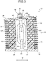
- a vibration isolation structure 10 includes a laminated rubber body 16 that is a composite laminated member formed from alternately stacked hard plates 12 that can be considered in practice to be rigid bodies and rubber plates 14 with viscoelastic characteristics.
- the laminated rubber body 16 is formed in a thick substantially circular cylinder shape, with a circular column shaped hollow section 17 provided at a central face portion of the laminated rubber body 16 so as to pierce through in the laminated rubber body 16 stacking direction (the arrow L direction).
- the laminated rubber body 16 is configured by bonding together the hard plates 12 and the rubber plates 14 using vulcanization.
- the hard plates 12 are circular plate shaped.
- the rubber plates 14 When viewed along the stacking direction L of the laminated rubber body 16, the rubber plates 14 are formed with straight lines at a first end side 16F and a second end side 16B, with the remainder of the external periphery arc shaped to follow the hard plates 12. Namely, the rubber plates 14 are formed with a two face width profile of a circular shape from which the first end side 16F and the second end side 16B have been cut off.
- the stacked rubber plates 14 are accordingly configured with flat faces facing each other at the first end side 16F and the second end side 16B.
- the vibration isolation structure 10 is coupled to a vibration generating section such that the connecting direction between the first end side 16F and the second end side 16B (referred to below as the shear direction W) is the vibration amplitude direction of input vibration. Coupling is made, for example, such that the shear direction W is aligned with the vehicle front-rear direction.
- a distance S1 between the first end side 16F and the second end side 16B is shorter than the distance between other end portions, namely than the diameter A of the hard plates 12. Due to the surface area of the rubber plates 14 constrained by the hard plates 12 hence being narrower in the shear direction W, the hydrostatic stress to tensional load acting on the rubber plates 14 at the first end side 16F or the second end side 16B (on the second end side 16B in Fig. 3 ) when twisting deformation occurs in the laminated rubber body 16 (see Fig. 3 ) is reduced. Note that the distance S1 is preferably 65% to 90% of the diameter A.
- Examples of substances that may be employed for the hard plates 12 configuring the laminated rubber body 16 include for example, metal, ceramic, plastics, FRP, polyurethane, wood, paperboard, cement board and faced plywood.
- the rubber plates 14 are generally formed by molding raw materials of various types of vulcanized rubber. Examples of the types of rubber include ethylene propylene rubbers (EPR, EPDM), nitrile rubbers (NBR), butyl rubbers, halogenated butyl rubbers, chloroprene rubbers (CR), natural rubbers (NR), isoprene rubbers (IR), styrene butadiene rubbers (SBR) and butadiene rubbers (BR).
- EPR ethylene propylene rubbers
- NBR nitrile rubbers
- butyl rubbers butyl rubbers
- halogenated butyl rubbers chloroprene rubbers
- CR chloroprene rubbers
- NR natural rubbers
- IR isoprene rubbers
- a flange 18 and a flange 20 are respectively disposed at the laminated rubber body 16 stacking direction outside.
- the pair of flanges 18, 20 are respectively fixed to the bottom end face and the top end face of the laminated rubber body 16, such as by vulcanization, so as to sandwich the laminated rubber body 16 along the stacking direction.
- the flanges 18, 20 are each configured by rectangular shaped metal plates.
- a circular shaped opening 22 is formed at a central portion in the bottom end side flange 18 adjacent to the hollow section 17 of the laminated rubber body 16, and an indented shaped insertion fit portion 24 is formed along the peripheral edge portion of the opening 22 at the bottom face of the flange 18.
- An insertion hole 26 is formed through a central portion of the top end side flange 20 with a smaller diameter than that of the hollow section 17 of the laminated rubber body 16.
- a metal link chain 28 is disposed inside the hollow section 17 of the laminated rubber body 16 of the vibration isolation structure 10 as a displacement restricting member.
- the link chain 28 is disposed such that its length direction is aligned with the laminated rubber body 16 stacking direction, and the link chain 28 has rigidity and strength to tensional load in the stacking direction that is sufficiently higher than those of the laminated rubber body 16.
- the link chain 28 is configured from plural individual (three in the present exemplary embodiment) links 30, 31, 32 connected together in a line.
- the link chain 28 is easily capable of deforming overall in the shear direction W which is orthogonal to the stacking direction by bending between the respective links 30, 31, 32.
- the link 30 positioned at the bottommost portion of the link chain 28 is fixed to a circular plate shaped lid member 34 disposed at the bottom end portion of the link 30, such as by welding.
- the link 32 positioned at the uppermost portion of the link chain 28 is fixed to a bolt shaft 36 disposed at the top end portion of the link 32 so as to project out upwards, such as by welding.
- the link chain 28 is inserted into the hollow section 17 of the laminated rubber body 16 through the opening 22 of the bottom end side flange 18.
- the bolt shaft 36 is inserted through the insertion hole 26 of the flange 20, and the leading end side of the bolt shaft 36 projects out externally from the flange 20.
- the lid member 34 closes off the opening 22 of the flange 18 and the outer peripheral portion of the lid member 34 is inserted into the insertion fit portion 24 of the flange 18.
- a washer 38 is fitted over the leading end portion of the bolt shaft 36 that projects out from the flange 20, and a nut 40 is then screwed on.
- the link chain 28 disposed inside the hollow section 17 accordingly has a bottom end portion that is connected and fixed to the flange 18 though the lid member 34, and has a top end portion that is connected and fixed to the flange 20 through the bolt shaft 36.
- the laminated rubber body 16 is then placed in a compressed state to a specific compression ratio by pressing along the stacking direction by for example disposing in a press.
- the nut 40 that is screwed onto the bolt shaft 36 that projects out from the flange 20 is then tightened onto the bolt shaft 36 until there is no slack between the nut 40 and the flange 20 and until a specific fastening torque is generated.
- the laminated rubber body 16 is thereby retained by the flanges 18, 20 in a compressed state compressed by the specific compression ratio along the stacking direction.
- the resilient rebound force from the compressed-state laminated rubber body 16 borne by the flanges 18, 20 is supported by the link chain 28, such that the link chain 28 is in a pulled state (tensioned state) due to the rebound force.
- the laminated rubber body 16 When not supporting the vibration generating section, and not bearing compression load from the vibration generating section along the stacking direction, the laminated rubber body 16 is retained in a compressed state with a compression ratio greater than 0% up to 5% in the stacking direction.
- the laminated rubber body 16 is preferably retained in a compressed state with a compression ratio greater than 0% up to 2% in the stacking direction, and is more preferably retained in a compressed state with a compression ratio greater than 0% and in the vicinity of 0% in a range of + 0.5% in the stacking direction.
- the laminated rubber body 16 is maintained in a compressed state when the compression load is input from the vibration generating section along the stacking direction, compressed with a compression ratio along the stacking direction greater than 0% up to 20%.
- the laminated rubber body 16 is preferably maintained in a compressed state with a compression ratio along the stacking direction of greater than 0% and less than 10%, and more preferably maintained in a compressed state with a compression ratio along the stacking direction of greater than 0% and less than 5%.
- the vibration isolation structure 10 of the present exemplary embodiment is, for example, interposed between a vibration generating section such as an engine or motor and a vibration receiving section such as a floor or vehicle body.
- the vibration isolation structure 10 supports the vibration generating section on the vibration receiving section.
- the laminated rubber body 16 is coupled to the vibration generating section such that the shear direction W is along the vibration amplitude direction of for example the floor or the vehicle body.
- coupling is made such that the shear direction W corresponds to the front-rear direction of the vehicle.
- the laminated rubber body 16 When vibration is generated from the vibration generating section, the laminated rubber body 16 mainly deforms in the shear direction W and attenuates and absorbs vibration such as by internal friction.
- the distance S1 from the first end side 16F to the second end side 16B of the rubber plates 14 is shorter than the diameter A of the laminated rubber body 16. Consequently, the hydrostatic stress to the tensional load acting on the first end side 16F or the second end side 16B (on the second end side 16B in Fig. 3 ) when twisting deformation occurs in the laminated rubber body 16 (see Fig. 3 ) can be reduced. As a result damage to the rubber plates 14 from input vibrations having large amplitude along the shear direction W can be effectively suppressed.
- the outer edges of portions of the rubber plates 14 other than the first end side 16F and the second end side 16B are formed in arc shapes, and so hitherto attained rigidity can be maintained for these portions, and any drop in rigidity can be suppressed to a small amount.
- the link chain 28 with the plural individual links 30, 31, 32 connected together in a line is employed as the displacement restricting member.
- configuration may be made employing a strand shaped member, such as metal strands, a metal wire of twisted metal strands, or a cord-like member such as a member formed from a resin with for example aramid fibers.
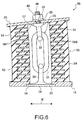
- Second Exemplary Embodiment - Vibration Isolation Structure Configuration Fig. 4 to Fig. 6 illustrate a vibration isolation structure according to a second exemplary embodiment, which is according to the present invention. Note that portions of a vibration isolation structure 50 according to the present exemplary embodiment similar to those of the vibration isolation structure 10 according to the first exemplary embodiment are allocated the same reference numbers and further explanation thereof is omitted.
- the points where the vibration isolation structure 50 according to the present exemplary embodiment differ from the vibration isolation structure 10 according to the first exemplary embodiment are in that, as viewed from the stacking direction L, the hard plates are formed in a similar shape to the rubber plates 14 in the first exemplary embodiment, and the rubber plates are formed in a similar shape to the hard plates 12 of the first exemplary embodiment.
- the vibration isolation structure 50 of the present exemplary embodiment is equipped with a laminated rubber body 56 that is a composite laminated member formed from alternately stacked hard plates 52 and rubber plates 54.
- a laminated rubber body 56 that is a composite laminated member formed from alternately stacked hard plates 52 and rubber plates 54.
- Each of the hard plates 52 of the present exemplary embodiment as viewed along a stacking direction L of the laminated rubber body 56, has a straight line first end side 56F and a second end side 56B, with the remainder of the outer edge configured in an arc shape.
- the hard plates 52 are formed with a two face width profile of a circular shape from which the first end side 56F and the second end side 56B have been cut off.
- the vibration isolation structure 50 is coupled to a vibration generating section such that the connecting direction between the first end side 56F and the second end side 56B (the shear direction W) lies along the amplitude direction of input vibration. Coupling is made, for example, such that the shear direction W is aligned with the vehicle front-rear direction.
- a distance S2 in the hard plates 52 between the first end side 56F and the second end side 56B is shorter than the distance between other end portions, namely than a circular plate diameter A.
- the free surface area of the rubber plates 54 is accordingly widened in the shear direction W, and when twisting deformation occurs in the laminated rubber body 56 (see Fig. 6 ) the hydrostatic stress to the tensional load acting on the first end side 56F or the second end side 56B (on the second end side 56B in Fig. 6 ) is reduced.
- the distance S2 is preferably 65% to 90% of the diameter A.
- the rubber plates 54 of the present exemplary embodiment are circular plate shaped as viewed along the stacking direction L, and are formed continuous in the stacking direction L at the first end side 56F and the second end side 56B so as to infill the cut-off portions of the hard plates 52.
- the laminated rubber body 56 When vibration is generated from the vibration generating section, the laminated rubber body 56 mainly deforms in the shear direction W, and attenuates and absorbs vibration by for example internal friction. When vibration of large amplitude along the shear direction W is input, as shown in Fig. 6 , twisting deformation occurs in the laminated rubber body 56, and tensional load acts on the first end side 56F or the second end side 56B (the second end side 56B in Fig. 6 ) that are disposed along the amplitude direction of the laminated rubber body 56.
- the link chain 28 has been placed in a tensioned state, and so a portion of the tensional load is supported by the link chain 28, enabling the tensional stress occurring in the laminated rubber body 56 along the stacking direction to be reduced.
- the distance S2 in the hard plates 52 from the first end side 56F to the second end side 56B is shorter than the diameter A of the laminated rubber body 56. Consequently, when twisting deformation has occurred in the laminated rubber body 56 (see Fig. 6 ) the hydrostatic stress from tensional load acting on the first end side 56F or the second end side 56B (the second end side 56B in Fig. 6 ) can be reduced. As a result damage to the rubber plates 54 from input vibration with large amplitude along the shear direction W can be effectively suppressed.
- portions of the rubber plates 54 other than the first end side 56F and the second end side 56B are configured with arc shaped outer edges, and so hitherto attained rigidity can be maintained for these portions, and any drop in rigidity can be made small.
- the distance (distance S1 or distance S2) of the shear direction W is only made shorter than the diameter A for one type of plate out of the hard plates or the rubber plates, the distance of the shear direction W may be made shorter than the diameter A for both the hard plates and the rubber plates.
- FIG. 7 to Fig. 9 illustrate a vibration isolation structure according to a third exemplary embodiment, which is not according to the present invention. Note that portions of a vibration isolation structure 60 according to the present exemplary embodiment similar to those of the vibration isolation structures 10, 50 of the first and second exemplary embodiments are allocated the same reference numerals and further explanation thereof is omitted.
- the points in which the vibration isolation structure 60 according to the present exemplary embodiment differs from the vibration isolation structure 10 according to the first exemplary embodiment are in that, as viewed along the stacking direction L, the rubber plates are formed in a similar shape to the hard plates 12 of the first exemplary embodiment, and the rubber plates are configured with hollow portions.
- the vibration isolation structure 60 is equipped with a laminated rubber body 66 that is a composite laminated member formed from alternately stacked hard plates 62 and rubber plates 64.
- a laminated rubber body 66 that is a composite laminated member formed from alternately stacked hard plates 62 and rubber plates 64.
- Each of the hard plates 62 and the rubber plates 64 of the present exemplary embodiment is formed in a circular plate shape.
- each of the rubber plates 64 as viewed along a stacking direction L of the laminated rubber body 66, hollow portions 68 are formed along a direction orthogonal to the shear direction W at a first end side 66F and the second end side 66B.
- the hollow portions 68 are formed so as to pass through the rubber plates 64.
- the vibration isolation structure 60 is coupled to a vibration generating section such that the direction connecting the first end side 66F and the second end side 66B (shear direction W) lies along the amplitude direction of input vibration. Coupling is made, for example, such that the shear direction W is aligned with the vehicle front-rear direction.
- the free surface area of the rubber plates 64 is accordingly widened in the shear direction W, and when twisting deformation occurs in the laminated rubber body 66 (see Fig. 9 ) the hydrostatic stress to the tensional load acting at the first end side 66F or the second end side 66B (on the second end side 66B in Fig. 9 ) is reduced.
- the positions where the hollow portions 68 are formed is preferably in a range of 30% to 60% of a radius B from the outer periphery of the rubber plates 64, at a distance E from the outer periphery. This is because the hydrostatic stress cannot be effectively lowered when the hollow portions 68 are configured further to the peripheral outside than 30% of the radius B, or when configured further to the peripheral inside than 60% of the radius B.
- the laminated rubber body 66 When vibration is generated from the vibration generating section, the laminated rubber body 66 mainly deforms in the shear direction W, and attenuates and absorbs vibration by for example internal friction. When vibration of large amplitude along the shear direction W is input, as shown in Fig. 9 , twisting deformation occurs in the laminated rubber body 66, and tensional load acts on the first end side 66F or the second end side 66B (the second end side 66B in Fig. 9 ) along the amplitude direction of the laminated rubber body 66.
- the link chain 28 has been placed in a tensioned state, and so a portion of the tensional load is supported by the link chain 28, enabling the tensional stress occurring in the laminated rubber body 66 along the stacking direction to be reduced.
- the hollow portions 68 are formed in the rubber plates 64 at the first end side 66F and the second end side 66B. Consequently, when twisting deformation has occurred in the laminated rubber body 66 (see Fig. 9 ) the hydrostatic stress from tensional load acting on the first end side 66F or the second end side 66B (the second end side 66B in Fig. 9 ) can be reduced. As a result damage to the rubber plates 64 from input vibration with large amplitude along the shear direction W can be effectively suppressed.
- the rubber plates 64 of the present exemplary embodiment are also formed further to the radial direction outside than the hollow portions 68, and so any drop in rigidity can be made small while still reducing the hydrostatic stress in the manner described above.
- the hollow portions 68 are formed along a direction orthogonal to the shear direction W, however hollow portions may be formed in another direction, for example formed in a direction along the shear direction W, or a radial direction to reduce the hydrostatic stress.
- the chain 28 is disposed between the flanges 18, 20, and the laminated rubber bodies 16, 56, 66 are maintained in a compressed state, however configuration may be made without the chain 28.
- Fig. 10 is a graph illustrating such results.
- the first and the second exemplary embodiments both obtain substantially the same advantageous effects.
- the hydrostatic stress value M increases and the displacement magnification amount D gets smaller as the distance S1/ diameter A and the distance S2/ diameter A increases.
- the hydrostatic stress is lowered by 10% and the displacement magnification amount increases by 10% in the vicinity of 90% for the distance S1/diameter A (the distance S2/ diameter A).
- the increase in displacement magnification amount exceeds 50% at 65% or less for the distance S1/diameter A (the distance S2/ diameter A). It is accordingly preferable to set the distance S1/diameter A (the distance S2/ diameter A) at 65% to 90% in order to lower the hydrostatic stress while still securing an appropriate displacement amount.
Landscapes
- Engineering & Computer Science (AREA)
- General Engineering & Computer Science (AREA)
- Architecture (AREA)
- Mechanical Engineering (AREA)
- Vibration Prevention Devices (AREA)
- Springs (AREA)
Applications Claiming Priority (2)
| Application Number | Priority Date | Filing Date | Title |
|---|---|---|---|
| JP2010048381A JP5538957B2 (ja) | 2010-03-04 | 2010-03-04 | 防振構造体 |
| PCT/JP2011/054780 WO2011108597A1 (ja) | 2010-03-04 | 2011-03-02 | 防振構造体 |
Publications (3)
| Publication Number | Publication Date |
|---|---|
| EP2543908A1 EP2543908A1 (en) | 2013-01-09 |
| EP2543908A4 EP2543908A4 (en) | 2015-10-28 |
| EP2543908B1 true EP2543908B1 (en) | 2017-08-16 |
Family
ID=44542244
Family Applications (1)
| Application Number | Title | Priority Date | Filing Date |
|---|---|---|---|
| EP11750706.1A Not-in-force EP2543908B1 (en) | 2010-03-04 | 2011-03-02 | Vibration isolation structure |
Country Status (5)
| Country | Link |
|---|---|
| US (1) | US8864115B2 (zh) |
| EP (1) | EP2543908B1 (zh) |
| JP (1) | JP5538957B2 (zh) |
| CN (2) | CN103982583B (zh) |
| WO (1) | WO2011108597A1 (zh) |
Families Citing this family (10)
| Publication number | Priority date | Publication date | Assignee | Title |
|---|---|---|---|---|
| CN102829115A (zh) * | 2012-08-28 | 2012-12-19 | 中国航空工业集团公司北京航空材料研究院 | 一种汽车悬架减振橡胶弹簧 |
| JP6076849B2 (ja) * | 2013-07-03 | 2017-02-08 | 株式会社ブリヂストン | 防振構造体 |
| CA2922707C (en) * | 2013-09-06 | 2020-05-26 | Bryan Willis Robinson | Anchorage connector for a safety system |
| JP2016061410A (ja) * | 2014-09-19 | 2016-04-25 | オイレス工業株式会社 | 構造物用振動減衰装置 |
| CN106032829B (zh) * | 2015-03-10 | 2021-05-11 | 艾默生环境优化技术(苏州)有限公司 | 隔振垫以及包括该隔振垫的压缩机系统 |
| DE102015109533B4 (de) * | 2015-06-15 | 2019-03-21 | Benteler Automobiltechnik Gmbh | Gummi-Feststofflager zur Anordnung an einer Kraftfahrzeugachse |
| JP6613930B2 (ja) * | 2016-02-01 | 2019-12-04 | オイレス工業株式会社 | 免震装置 |
| JP6579026B2 (ja) * | 2016-04-15 | 2019-09-25 | オイレス工業株式会社 | 橋梁用の免震支承及びそれを用いた橋梁 |
| DK3462053T3 (da) * | 2017-09-20 | 2020-12-07 | Zhuzhou Times New Mat Tech Co | Vibrationsdæmpende støtteindretning |
| TR201922885A2 (tr) * | 2019-12-31 | 2021-07-26 | Sem Lastik Sanayii Ve Ticaret Anonim Sirketi | Bağlanti takozu |
Family Cites Families (13)
| Publication number | Priority date | Publication date | Assignee | Title |
|---|---|---|---|---|
| US3997151A (en) * | 1975-05-21 | 1976-12-14 | Lord Corporation | Modular cushioning pad |
| US5014474A (en) * | 1989-04-24 | 1991-05-14 | Fyfe Edward R | System and apparatus for limiting the effect of vibrations between a structure and its foundation |
| JPH05141464A (ja) * | 1991-11-15 | 1993-06-08 | Kajima Corp | 積層ゴム支承及び該積層ゴム支承を用いた構造物の振動制御装置 |
| US5676356A (en) * | 1996-05-30 | 1997-10-14 | The Boler Company | Flexible bolster |
| US7201367B2 (en) * | 2002-12-12 | 2007-04-10 | Caterpillar Inc | Load-bearing resilient mount |
| JP2004211837A (ja) * | 2003-01-07 | 2004-07-29 | Kawaguchi Metal Industries Co Ltd | 免震装置 |
| JP2005090706A (ja) * | 2003-09-19 | 2005-04-07 | Bridgestone Corp | 免震構造体及び免震構造体製造方法 |
| JP4828877B2 (ja) * | 2004-07-21 | 2011-11-30 | 株式会社ブリヂストン | 防振構造体 |
| JP2006064119A (ja) | 2004-08-27 | 2006-03-09 | Tokai Rubber Ind Ltd | 流体封入式防振装置 |
| JP4734913B2 (ja) * | 2004-12-20 | 2011-07-27 | 横浜ゴム株式会社 | 免震用ゴム積層体 |
| JP2008075743A (ja) * | 2006-09-21 | 2008-04-03 | Bridgestone Corp | 防振構造体及び防振構造体の製造方法 |
| JP5373274B2 (ja) * | 2006-09-22 | 2013-12-18 | 株式会社ブリヂストン | 防振構造体 |
| JP5207186B2 (ja) * | 2008-03-31 | 2013-06-12 | 公益財団法人鉄道総合技術研究所 | 弾性支持体 |
-
2010
- 2010-03-04 JP JP2010048381A patent/JP5538957B2/ja not_active Expired - Fee Related
-
2011
- 2011-03-02 WO PCT/JP2011/054780 patent/WO2011108597A1/ja active Application Filing
- 2011-03-02 CN CN201410199284.1A patent/CN103982583B/zh not_active Expired - Fee Related
- 2011-03-02 CN CN201180012089.8A patent/CN102782359B/zh not_active Expired - Fee Related
- 2011-03-02 US US13/582,665 patent/US8864115B2/en active Active
- 2011-03-02 EP EP11750706.1A patent/EP2543908B1/en not_active Not-in-force
Also Published As
| Publication number | Publication date |
|---|---|
| CN102782359A (zh) | 2012-11-14 |
| JP5538957B2 (ja) | 2014-07-02 |
| US20120326366A1 (en) | 2012-12-27 |
| WO2011108597A1 (ja) | 2011-09-09 |
| EP2543908A4 (en) | 2015-10-28 |
| JP2011185308A (ja) | 2011-09-22 |
| CN102782359B (zh) | 2015-08-26 |
| EP2543908A1 (en) | 2013-01-09 |
| US8864115B2 (en) | 2014-10-21 |
| CN103982583A (zh) | 2014-08-13 |
| CN103982583B (zh) | 2016-03-23 |
Similar Documents
| Publication | Publication Date | Title |
|---|---|---|
| EP2543908B1 (en) | Vibration isolation structure | |
| US9903433B2 (en) | Anti-vibration structure | |
| JP2008075743A (ja) | 防振構造体及び防振構造体の製造方法 | |
| JP5373274B2 (ja) | 防振構造体 | |
| EP2532918B1 (en) | Vibration-damping device | |
| JP6157000B2 (ja) | 防振装置 | |
| US9334923B2 (en) | Metal belt for continuously variable transmission | |
| JP4828877B2 (ja) | 防振構造体 | |
| JP4724614B2 (ja) | 防振装置 | |
| RU2424149C2 (ru) | Амортизатор колеса мотоцикла | |
| JP2007309451A (ja) | 防振具 | |
| US20040170791A1 (en) | Power steering hose | |
| JP4671916B2 (ja) | 防振装置 | |
| JP6309597B2 (ja) | 防振構造体 | |
| JP2014206197A (ja) | 防振支持装置 | |
| JP2002357210A (ja) | 締結用弾性ゴムワッシャー | |
| JP2010019404A (ja) | 空気ばね装置 |
Legal Events
| Date | Code | Title | Description |
|---|---|---|---|
| PUAI | Public reference made under article 153(3) epc to a published international application that has entered the european phase |
Free format text: ORIGINAL CODE: 0009012 |
|
| 17P | Request for examination filed |
Effective date: 20120913 |
|
| AK | Designated contracting states |
Kind code of ref document: A1 Designated state(s): AL AT BE BG CH CY CZ DE DK EE ES FI FR GB GR HR HU IE IS IT LI LT LU LV MC MK MT NL NO PL PT RO RS SE SI SK SM TR |
|
| DAX | Request for extension of the european patent (deleted) | ||
| RA4 | Supplementary search report drawn up and despatched (corrected) |
Effective date: 20150929 |
|
| RIC1 | Information provided on ipc code assigned before grant |
Ipc: F16F 15/04 20060101AFI20150923BHEP Ipc: F16F 1/44 20060101ALI20150923BHEP Ipc: F16F 1/40 20060101ALI20150923BHEP |
|
| GRAP | Despatch of communication of intention to grant a patent |
Free format text: ORIGINAL CODE: EPIDOSNIGR1 |
|
| INTG | Intention to grant announced |
Effective date: 20170222 |
|
| GRAS | Grant fee paid |
Free format text: ORIGINAL CODE: EPIDOSNIGR3 |
|
| GRAA | (expected) grant |
Free format text: ORIGINAL CODE: 0009210 |
|
| AK | Designated contracting states |
Kind code of ref document: B1 Designated state(s): AL AT BE BG CH CY CZ DE DK EE ES FI FR GB GR HR HU IE IS IT LI LT LU LV MC MK MT NL NO PL PT RO RS SE SI SK SM TR |
|
| REG | Reference to a national code |
Ref country code: GB Ref legal event code: FG4D |
|
| REG | Reference to a national code |
Ref country code: CH Ref legal event code: EP |
|
| REG | Reference to a national code |
Ref country code: IE Ref legal event code: FG4D |
|
| REG | Reference to a national code |
Ref country code: AT Ref legal event code: REF Ref document number: 919374 Country of ref document: AT Kind code of ref document: T Effective date: 20170915 |
|
| REG | Reference to a national code |
Ref country code: DE Ref legal event code: R096 Ref document number: 602011040630 Country of ref document: DE |
|
| REG | Reference to a national code |
Ref country code: SE Ref legal event code: TRGR |
|
| REG | Reference to a national code |
Ref country code: NL Ref legal event code: MP Effective date: 20170816 |
|
| REG | Reference to a national code |
Ref country code: LT Ref legal event code: MG4D |
|
| REG | Reference to a national code |
Ref country code: AT Ref legal event code: MK05 Ref document number: 919374 Country of ref document: AT Kind code of ref document: T Effective date: 20170816 |
|
| PG25 | Lapsed in a contracting state [announced via postgrant information from national office to epo] |
Ref country code: NL Free format text: LAPSE BECAUSE OF FAILURE TO SUBMIT A TRANSLATION OF THE DESCRIPTION OR TO PAY THE FEE WITHIN THE PRESCRIBED TIME-LIMIT Effective date: 20170816 Ref country code: FI Free format text: LAPSE BECAUSE OF FAILURE TO SUBMIT A TRANSLATION OF THE DESCRIPTION OR TO PAY THE FEE WITHIN THE PRESCRIBED TIME-LIMIT Effective date: 20170816 Ref country code: AT Free format text: LAPSE BECAUSE OF FAILURE TO SUBMIT A TRANSLATION OF THE DESCRIPTION OR TO PAY THE FEE WITHIN THE PRESCRIBED TIME-LIMIT Effective date: 20170816 Ref country code: LT Free format text: LAPSE BECAUSE OF FAILURE TO SUBMIT A TRANSLATION OF THE DESCRIPTION OR TO PAY THE FEE WITHIN THE PRESCRIBED TIME-LIMIT Effective date: 20170816 Ref country code: NO Free format text: LAPSE BECAUSE OF FAILURE TO SUBMIT A TRANSLATION OF THE DESCRIPTION OR TO PAY THE FEE WITHIN THE PRESCRIBED TIME-LIMIT Effective date: 20171116 |
|
| PG25 | Lapsed in a contracting state [announced via postgrant information from national office to epo] |
Ref country code: ES Free format text: LAPSE BECAUSE OF FAILURE TO SUBMIT A TRANSLATION OF THE DESCRIPTION OR TO PAY THE FEE WITHIN THE PRESCRIBED TIME-LIMIT Effective date: 20170816 Ref country code: GR Free format text: LAPSE BECAUSE OF FAILURE TO SUBMIT A TRANSLATION OF THE DESCRIPTION OR TO PAY THE FEE WITHIN THE PRESCRIBED TIME-LIMIT Effective date: 20171117 Ref country code: PL Free format text: LAPSE BECAUSE OF FAILURE TO SUBMIT A TRANSLATION OF THE DESCRIPTION OR TO PAY THE FEE WITHIN THE PRESCRIBED TIME-LIMIT Effective date: 20170816 Ref country code: LV Free format text: LAPSE BECAUSE OF FAILURE TO SUBMIT A TRANSLATION OF THE DESCRIPTION OR TO PAY THE FEE WITHIN THE PRESCRIBED TIME-LIMIT Effective date: 20170816 Ref country code: RS Free format text: LAPSE BECAUSE OF FAILURE TO SUBMIT A TRANSLATION OF THE DESCRIPTION OR TO PAY THE FEE WITHIN THE PRESCRIBED TIME-LIMIT Effective date: 20170816 Ref country code: BG Free format text: LAPSE BECAUSE OF FAILURE TO SUBMIT A TRANSLATION OF THE DESCRIPTION OR TO PAY THE FEE WITHIN THE PRESCRIBED TIME-LIMIT Effective date: 20171116 Ref country code: IS Free format text: LAPSE BECAUSE OF FAILURE TO SUBMIT A TRANSLATION OF THE DESCRIPTION OR TO PAY THE FEE WITHIN THE PRESCRIBED TIME-LIMIT Effective date: 20171216 |
|
| PG25 | Lapsed in a contracting state [announced via postgrant information from national office to epo] |
Ref country code: RO Free format text: LAPSE BECAUSE OF FAILURE TO SUBMIT A TRANSLATION OF THE DESCRIPTION OR TO PAY THE FEE WITHIN THE PRESCRIBED TIME-LIMIT Effective date: 20170816 Ref country code: DK Free format text: LAPSE BECAUSE OF FAILURE TO SUBMIT A TRANSLATION OF THE DESCRIPTION OR TO PAY THE FEE WITHIN THE PRESCRIBED TIME-LIMIT Effective date: 20170816 Ref country code: CZ Free format text: LAPSE BECAUSE OF FAILURE TO SUBMIT A TRANSLATION OF THE DESCRIPTION OR TO PAY THE FEE WITHIN THE PRESCRIBED TIME-LIMIT Effective date: 20170816 |
|
| REG | Reference to a national code |
Ref country code: DE Ref legal event code: R097 Ref document number: 602011040630 Country of ref document: DE |
|
| PG25 | Lapsed in a contracting state [announced via postgrant information from national office to epo] |
Ref country code: SM Free format text: LAPSE BECAUSE OF FAILURE TO SUBMIT A TRANSLATION OF THE DESCRIPTION OR TO PAY THE FEE WITHIN THE PRESCRIBED TIME-LIMIT Effective date: 20170816 Ref country code: SK Free format text: LAPSE BECAUSE OF FAILURE TO SUBMIT A TRANSLATION OF THE DESCRIPTION OR TO PAY THE FEE WITHIN THE PRESCRIBED TIME-LIMIT Effective date: 20170816 Ref country code: IT Free format text: LAPSE BECAUSE OF FAILURE TO SUBMIT A TRANSLATION OF THE DESCRIPTION OR TO PAY THE FEE WITHIN THE PRESCRIBED TIME-LIMIT Effective date: 20170816 Ref country code: EE Free format text: LAPSE BECAUSE OF FAILURE TO SUBMIT A TRANSLATION OF THE DESCRIPTION OR TO PAY THE FEE WITHIN THE PRESCRIBED TIME-LIMIT Effective date: 20170816 |
|
| PLBE | No opposition filed within time limit |
Free format text: ORIGINAL CODE: 0009261 |
|
| STAA | Information on the status of an ep patent application or granted ep patent |
Free format text: STATUS: NO OPPOSITION FILED WITHIN TIME LIMIT |
|
| 26N | No opposition filed |
Effective date: 20180517 |
|
| PG25 | Lapsed in a contracting state [announced via postgrant information from national office to epo] |
Ref country code: SI Free format text: LAPSE BECAUSE OF FAILURE TO SUBMIT A TRANSLATION OF THE DESCRIPTION OR TO PAY THE FEE WITHIN THE PRESCRIBED TIME-LIMIT Effective date: 20170816 |
|
| REG | Reference to a national code |
Ref country code: DE Ref legal event code: R119 Ref document number: 602011040630 Country of ref document: DE |
|
| REG | Reference to a national code |
Ref country code: CH Ref legal event code: PL |
|
| PG25 | Lapsed in a contracting state [announced via postgrant information from national office to epo] |
Ref country code: MC Free format text: LAPSE BECAUSE OF FAILURE TO SUBMIT A TRANSLATION OF THE DESCRIPTION OR TO PAY THE FEE WITHIN THE PRESCRIBED TIME-LIMIT Effective date: 20170816 |
|
| REG | Reference to a national code |
Ref country code: BE Ref legal event code: MM Effective date: 20180331 |
|
| REG | Reference to a national code |
Ref country code: IE Ref legal event code: MM4A |
|
| PG25 | Lapsed in a contracting state [announced via postgrant information from national office to epo] |
Ref country code: LU Free format text: LAPSE BECAUSE OF NON-PAYMENT OF DUE FEES Effective date: 20180302 |
|
| PG25 | Lapsed in a contracting state [announced via postgrant information from national office to epo] |
Ref country code: IE Free format text: LAPSE BECAUSE OF NON-PAYMENT OF DUE FEES Effective date: 20180302 Ref country code: DE Free format text: LAPSE BECAUSE OF NON-PAYMENT OF DUE FEES Effective date: 20181002 |
|
| PG25 | Lapsed in a contracting state [announced via postgrant information from national office to epo] |
Ref country code: BE Free format text: LAPSE BECAUSE OF NON-PAYMENT OF DUE FEES Effective date: 20180331 Ref country code: CH Free format text: LAPSE BECAUSE OF NON-PAYMENT OF DUE FEES Effective date: 20180331 Ref country code: LI Free format text: LAPSE BECAUSE OF NON-PAYMENT OF DUE FEES Effective date: 20180331 |
|
| PG25 | Lapsed in a contracting state [announced via postgrant information from national office to epo] |
Ref country code: FR Free format text: LAPSE BECAUSE OF NON-PAYMENT OF DUE FEES Effective date: 20180331 |
|
| PG25 | Lapsed in a contracting state [announced via postgrant information from national office to epo] |
Ref country code: MT Free format text: LAPSE BECAUSE OF NON-PAYMENT OF DUE FEES Effective date: 20180302 |
|
| PG25 | Lapsed in a contracting state [announced via postgrant information from national office to epo] |
Ref country code: TR Free format text: LAPSE BECAUSE OF FAILURE TO SUBMIT A TRANSLATION OF THE DESCRIPTION OR TO PAY THE FEE WITHIN THE PRESCRIBED TIME-LIMIT Effective date: 20170816 |
|
| PGFP | Annual fee paid to national office [announced via postgrant information from national office to epo] |
Ref country code: SE Payment date: 20200323 Year of fee payment: 10 Ref country code: GB Payment date: 20200323 Year of fee payment: 10 |
|
| PG25 | Lapsed in a contracting state [announced via postgrant information from national office to epo] |
Ref country code: HU Free format text: LAPSE BECAUSE OF FAILURE TO SUBMIT A TRANSLATION OF THE DESCRIPTION OR TO PAY THE FEE WITHIN THE PRESCRIBED TIME-LIMIT; INVALID AB INITIO Effective date: 20110302 Ref country code: PT Free format text: LAPSE BECAUSE OF FAILURE TO SUBMIT A TRANSLATION OF THE DESCRIPTION OR TO PAY THE FEE WITHIN THE PRESCRIBED TIME-LIMIT Effective date: 20170816 |
|
| PG25 | Lapsed in a contracting state [announced via postgrant information from national office to epo] |
Ref country code: HR Free format text: LAPSE BECAUSE OF FAILURE TO SUBMIT A TRANSLATION OF THE DESCRIPTION OR TO PAY THE FEE WITHIN THE PRESCRIBED TIME-LIMIT Effective date: 20170816 Ref country code: CY Free format text: LAPSE BECAUSE OF FAILURE TO SUBMIT A TRANSLATION OF THE DESCRIPTION OR TO PAY THE FEE WITHIN THE PRESCRIBED TIME-LIMIT Effective date: 20170816 Ref country code: MK Free format text: LAPSE BECAUSE OF NON-PAYMENT OF DUE FEES Effective date: 20170816 |
|
| PG25 | Lapsed in a contracting state [announced via postgrant information from national office to epo] |
Ref country code: AL Free format text: LAPSE BECAUSE OF FAILURE TO SUBMIT A TRANSLATION OF THE DESCRIPTION OR TO PAY THE FEE WITHIN THE PRESCRIBED TIME-LIMIT Effective date: 20170816 |
|
| GBPC | Gb: european patent ceased through non-payment of renewal fee |
Effective date: 20210302 |
|
| PG25 | Lapsed in a contracting state [announced via postgrant information from national office to epo] |
Ref country code: SE Free format text: LAPSE BECAUSE OF NON-PAYMENT OF DUE FEES Effective date: 20210303 Ref country code: GB Free format text: LAPSE BECAUSE OF NON-PAYMENT OF DUE FEES Effective date: 20210302 |