EP2543870B1 - Einspritzdüse für Zweitakt-Dieselmotoren mit großem Hubraum und Turboaufladung - Google Patents
Einspritzdüse für Zweitakt-Dieselmotoren mit großem Hubraum und Turboaufladung Download PDFInfo
- Publication number
- EP2543870B1 EP2543870B1 EP12173372.9A EP12173372A EP2543870B1 EP 2543870 B1 EP2543870 B1 EP 2543870B1 EP 12173372 A EP12173372 A EP 12173372A EP 2543870 B1 EP2543870 B1 EP 2543870B1
- Authority
- EP
- European Patent Office
- Prior art keywords
- fuel
- valve
- valve needle
- axially movable
- actuation
- Prior art date
- Legal status (The legal status is an assumption and is not a legal conclusion. Google has not performed a legal analysis and makes no representation as to the accuracy of the status listed.)
- Active
Links
Images
Classifications
-
- F—MECHANICAL ENGINEERING; LIGHTING; HEATING; WEAPONS; BLASTING
- F02—COMBUSTION ENGINES; HOT-GAS OR COMBUSTION-PRODUCT ENGINE PLANTS
- F02M—SUPPLYING COMBUSTION ENGINES IN GENERAL WITH COMBUSTIBLE MIXTURES OR CONSTITUENTS THEREOF
- F02M47/00—Fuel-injection apparatus operated cyclically with fuel-injection valves actuated by fluid pressure
- F02M47/02—Fuel-injection apparatus operated cyclically with fuel-injection valves actuated by fluid pressure of accumulator-injector type, i.e. having fuel pressure of accumulator tending to open, and fuel pressure in other chamber tending to close, injection valves and having means for periodically releasing that closing pressure
- F02M47/027—Electrically actuated valves draining the chamber to release the closing pressure
-
- F—MECHANICAL ENGINEERING; LIGHTING; HEATING; WEAPONS; BLASTING
- F02—COMBUSTION ENGINES; HOT-GAS OR COMBUSTION-PRODUCT ENGINE PLANTS
- F02D—CONTROLLING COMBUSTION ENGINES
- F02D19/00—Controlling engines characterised by their use of non-liquid fuels, pluralities of fuels, or non-fuel substances added to the combustible mixtures
- F02D19/06—Controlling engines characterised by their use of non-liquid fuels, pluralities of fuels, or non-fuel substances added to the combustible mixtures peculiar to engines working with pluralities of fuels, e.g. alternatively with light and heavy fuel oil, other than engines indifferent to the fuel consumed
- F02D19/08—Controlling engines characterised by their use of non-liquid fuels, pluralities of fuels, or non-fuel substances added to the combustible mixtures peculiar to engines working with pluralities of fuels, e.g. alternatively with light and heavy fuel oil, other than engines indifferent to the fuel consumed simultaneously using pluralities of fuels
- F02D19/10—Controlling engines characterised by their use of non-liquid fuels, pluralities of fuels, or non-fuel substances added to the combustible mixtures peculiar to engines working with pluralities of fuels, e.g. alternatively with light and heavy fuel oil, other than engines indifferent to the fuel consumed simultaneously using pluralities of fuels peculiar to compression-ignition engines in which the main fuel is gaseous
- F02D19/105—Controlling engines characterised by their use of non-liquid fuels, pluralities of fuels, or non-fuel substances added to the combustible mixtures peculiar to engines working with pluralities of fuels, e.g. alternatively with light and heavy fuel oil, other than engines indifferent to the fuel consumed simultaneously using pluralities of fuels peculiar to compression-ignition engines in which the main fuel is gaseous operating in a special mode, e.g. in a liquid fuel only mode for starting
-
- F—MECHANICAL ENGINEERING; LIGHTING; HEATING; WEAPONS; BLASTING
- F02—COMBUSTION ENGINES; HOT-GAS OR COMBUSTION-PRODUCT ENGINE PLANTS
- F02M—SUPPLYING COMBUSTION ENGINES IN GENERAL WITH COMBUSTIBLE MIXTURES OR CONSTITUENTS THEREOF
- F02M45/00—Fuel-injection apparatus characterised by having a cyclic delivery of specific time/pressure or time/quantity relationship
- F02M45/02—Fuel-injection apparatus characterised by having a cyclic delivery of specific time/pressure or time/quantity relationship with each cyclic delivery being separated into two or more parts
- F02M45/04—Fuel-injection apparatus characterised by having a cyclic delivery of specific time/pressure or time/quantity relationship with each cyclic delivery being separated into two or more parts with a small initial part, e.g. initial part for partial load and initial and main part for full load
- F02M45/08—Injectors peculiar thereto
-
- F—MECHANICAL ENGINEERING; LIGHTING; HEATING; WEAPONS; BLASTING
- F02—COMBUSTION ENGINES; HOT-GAS OR COMBUSTION-PRODUCT ENGINE PLANTS
- F02M—SUPPLYING COMBUSTION ENGINES IN GENERAL WITH COMBUSTIBLE MIXTURES OR CONSTITUENTS THEREOF
- F02M61/00—Fuel-injectors not provided for in groups F02M39/00 - F02M57/00 or F02M67/00
- F02M61/04—Fuel-injectors not provided for in groups F02M39/00 - F02M57/00 or F02M67/00 having valves, e.g. having a plurality of valves in series
- F02M61/042—The valves being provided with fuel passages
-
- F—MECHANICAL ENGINEERING; LIGHTING; HEATING; WEAPONS; BLASTING
- F02—COMBUSTION ENGINES; HOT-GAS OR COMBUSTION-PRODUCT ENGINE PLANTS
- F02M—SUPPLYING COMBUSTION ENGINES IN GENERAL WITH COMBUSTIBLE MIXTURES OR CONSTITUENTS THEREOF
- F02M61/00—Fuel-injectors not provided for in groups F02M39/00 - F02M57/00 or F02M67/00
- F02M61/16—Details not provided for in, or of interest apart from, the apparatus of groups F02M61/02 - F02M61/14
- F02M61/161—Means for adjusting injection-valve lift
-
- F—MECHANICAL ENGINEERING; LIGHTING; HEATING; WEAPONS; BLASTING
- F02—COMBUSTION ENGINES; HOT-GAS OR COMBUSTION-PRODUCT ENGINE PLANTS
- F02M—SUPPLYING COMBUSTION ENGINES IN GENERAL WITH COMBUSTIBLE MIXTURES OR CONSTITUENTS THEREOF
- F02M61/00—Fuel-injectors not provided for in groups F02M39/00 - F02M57/00 or F02M67/00
- F02M61/16—Details not provided for in, or of interest apart from, the apparatus of groups F02M61/02 - F02M61/14
- F02M61/18—Injection nozzles, e.g. having valve seats; Details of valve member seated ends, not otherwise provided for
- F02M61/1806—Injection nozzles, e.g. having valve seats; Details of valve member seated ends, not otherwise provided for characterised by the arrangement of discharge orifices, e.g. orientation or size
- F02M61/182—Discharge orifices being situated in different transversal planes with respect to valve member direction of movement
-
- F—MECHANICAL ENGINEERING; LIGHTING; HEATING; WEAPONS; BLASTING
- F02—COMBUSTION ENGINES; HOT-GAS OR COMBUSTION-PRODUCT ENGINE PLANTS
- F02M—SUPPLYING COMBUSTION ENGINES IN GENERAL WITH COMBUSTIBLE MIXTURES OR CONSTITUENTS THEREOF
- F02M2547/00—Special features for fuel-injection valves actuated by fluid pressure
- F02M2547/003—Valve inserts containing control chamber and valve piston
-
- Y—GENERAL TAGGING OF NEW TECHNOLOGICAL DEVELOPMENTS; GENERAL TAGGING OF CROSS-SECTIONAL TECHNOLOGIES SPANNING OVER SEVERAL SECTIONS OF THE IPC; TECHNICAL SUBJECTS COVERED BY FORMER USPC CROSS-REFERENCE ART COLLECTIONS [XRACs] AND DIGESTS
- Y02—TECHNOLOGIES OR APPLICATIONS FOR MITIGATION OR ADAPTATION AGAINST CLIMATE CHANGE
- Y02T—CLIMATE CHANGE MITIGATION TECHNOLOGIES RELATED TO TRANSPORTATION
- Y02T10/00—Road transport of goods or passengers
- Y02T10/10—Internal combustion engine [ICE] based vehicles
- Y02T10/30—Use of alternative fuels, e.g. biofuels
Definitions
- the present invention relates to a fuel valve for large turbocharged two-stoke diesel engines, in particular to en electronically controlled fuel valve for the large turbocharged inflow two stroke diesel engines with cross heads.
- These engines are typically provided with two or three fuel valves arranged in each cylinder cover.
- the fuel valve is provided with a spring biased axially movable valve needle that acts as a movable valve member.
- a preset pressure typically 350 Bar
- a conventional nozzle has a longitudinal axis that is arranged roughly at an angle of 10 to 15 deg to the direction of the movement of the piston in the cylinder of the engine and the nozzle is provided with a central bore and a plurality of nozzle bores that direct the fuel away from the cylinder walls and into the combustion chamber.
- a known fuel valve of this type is the MAN Diesel slide fuel valve that has a design with a minimized sac volume of residual fuel.
- This known fuel valve has two positions: open with all nozzle holes in use or closed.
- the position of the axially movable valve needle is controlled by a pressure chamber in the valve housing above the axially movable valve needle.
- the pressure chamber is permanently connected to a high pressure fuel source via a throttled connection and connected to drain via a closable throttled connection. This construction causes substantial drain losses during valve open time and causes relatively slow closing and opening speeds of the fuel valve.
- Dual fuel engines need injection of relatively small amounts of fuel for pilot injection when the engine is operated with a gaseous fuel.
- Present technology does not allow an injection valve that is used for fuel oil operation to be used for the pilot injection and vice versa so additional small pilot injection valves are used for the pilot injection, which means that the duel fuel engine has double the amount of fuel valves compared to conventional engines that can only operate on fuel oil.
- DE19755062 discloses a fuel valve that has a valve needle moving axially in a bore of a valve body, with a sealing surface acting on the body. There is at least one injection aperture in the valve body wall.
- a control rod is co-axial with the valve member and ends in a control cavity with at least two run-outs to the fuel return line containing throttles, the second of which, at the side, can be closed by moving the control rod.
- This fuel valve can operate in two modes. The two different states provide for an opening stroke of the valve needle with two different lengths. In one mode the stroke length is such that all of the bores in the valve needle are open and in the other mode the stroke length is such that only a portion of the bores in the valve needle are open.
- the length of the stroke is determined by an electronically controlled two-position end stop via the activation and deactivation of an on/off type valve that regulates flow through the second run-out.
- an on/off type valve that regulates flow through the second run-out.
- a fuel valve for injecting fuel into the combustion chamber of a large two stroke diesel engine, the fuel valve comprising: a fuel valve housing, an elongated nozzle with a central bore and a closed front, a high pressure fuel inlet port for connection to a source of high pressure fuel, a conduit connecting the high pressure fuel inlet port to the nozzle, a resiliently biased and axially movable valve needle cooperating with a valve seat and configured to control the flow of fuel from the high pressure fuel inlet port to the nozzle, whereby lift of the axially movable valve needle allows flow from the high pressure fuel inlet port to the nozzle, a chamber above the valve seat connected to the conduit to receive pressurized fuel, a plurality of nozzle holes distributed axially and radially over the nozzle, a cut-off shaft moving in unison with the valve needle and received to be axially displaceable in the central bore in the nozzle for opening and closing the nozzle holes, the plurality of nozzle holes being distributed axially
- the linear actuator controls the magnitude of the lift of the axially movable valve needle in response to a control signal.
- the linear actuator is at least partially integrated into the axially movable valve needle.
- the linear actuator may comprise a linear electric motor operably coupled to an actuation spool received in an axial bore in the axially movable valve needle.
- the linear actuator comprises a linear electric motor operably coupled to an actuation spool received in an axial bore in an actuation section of the axially movable valve needle and the actuation spool is part of the hydraulic valve and configured to control the flow of fluid to and from the hydraulic linear actuator.
- housing of the linear actuator is rigidly connected to the fuel valve housing and an output shaft of the linear motor is operably connected to the actuation spool.
- the fuel valve may further comprise a pressure chamber in the valve housing disposed above the axially movable valve needle for urging the axially movable valve needle towards the valve seat when pressurized, where the actuation spool is configured to either connect the pressure chamber to the high pressure fuel inlet port or to connect the pressure chamber to drain or to close off the pressure chamber, depending on the position of the actuation spool relative to the axially movable valve needle.
- the actuation spool cooperates with a plurality of ports in the axially movable valve needle, the ports connect the high pressure fuel inlet port, to the drain and to the pressure chamber respectively.
- ports and the actuation spool are configured such that the axially movable valve needle follows the axial movement of the actuation spool relative to the valve housing.
- the linear motor provides an output shaft position signal or wherein a position sensor is coupled to the output shaft of the linear motor or to the actuation spool.
- the linear actuator provides an output shaft position signal or wherein a position sensor is coupled to the output shaft of the linear actuator or to the actuation spool.
- the interior of the cut-off shaft is hollow and the hollow interior is connected to the inlet port of the fuel valve when the valve needle is lifted from its seat.
- the flow area through the nozzle holes is determined by the amount of lift of the valve, needle.
- the fuel valve includes a pressure chamber in the valve housing disposed above the axially movable valve needle for urging the axially movable valve on needle towards the valve seat when pressurized, the linear electric motor being operably coupled to an actuation spool that is received in an axial bore in the axially movable valve needle with the actuation spool being configured to either connect the pressure chamber to the high pressure fuel inlet port or to connect the pressure chamber to drain or to close off the pressure chamber, depending on the position of the actuation spool relative to the axially movable valve needle.
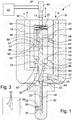
- the fuel valve 1 according to an exemplary embodiment illustrated in Fig. 1 has an external housing 10 which at its rearmost end has a fuel inlet port 16 and a fuel outlet port 18.
- the inlet port 16 is to be connected to a source P of high pressure fuel such as fuel oil, heavy fuel oil from a fuel pump or from a common fuel rail.
- the outlet port 18 is to be connected to a return line to tank T.
- the fuel valve 1 may in a known manner be mounted in the cylinder cover of a large two-stroke diesel engine and be connected with a fuel pump, not shown.
- the fuel inlet port 16 is in flow connection with a duct 17.
- Duct 17 extends to the seat of a valve needle 20 that is axially displaceable in an axial bore in the valve housing 10.
- the valve needle 20 is biased to its seat 22 by a closing spring 23.
- the foremost part of the valve housing 10 holds a nozzle 30 that projects from the valve housing 10 and into the combustion chamber of the engine cylinder (not shown) when the fuel valve 1 is mounted on the cylinder cover.
- Fig. 1 shows the valve needle 20 resting on the valve seat 22. In this position, fluid flow of fuel from the fuel oil inlet port 16 to the nozzle 30 is blocked. A chamber 25 above the valve seat 22 is connected to duct 17 to receive pressurized fuel.
- the valve needle 20 carries a foremost cut-off shaft 40 that is thinner than the rearmost section of the valve needle 20 and the cut-off shaft 40 projects into a central bore 33 in the nozzle 30.
- the cut-off shaft 40 is axially displaced in the central bore of the nozzle 30.
- the nozzle 30 is further provided with a plurality of nozzle holes 35 through which the fuel is injected into the combustion chamber from the central bore 33. Thus, during a fuel injection event a jet of fuel comes from the nozzle holes 35.
- the nozzle holes 35 are drilled into the nozzle.
- the centerline of each nozzle hole 35 may coincide roughly with the centerline of the central bore 33. However, the centerlines of the nozzle holes 35 do not have to coincide exactly with the centerline of the central bore 33.
- the cut-off shaft 40 is in an exemplary embodiment made as one piece of material with the valve needle 20.
- the cut-off shaft 40 is hollow and the hollow interior of the cut-off shaft 40 connects to the space downstream of the valve seat 22. Thus, when the valve needle 20 is lifted from its seat the flow path extends all the way from the fuel oil inlet 16 to the hollow interior of the cut-off shaft 40.
- a duct 19 is connected to the outlet port 18 and the duct 19 collects the return oil flow as will de explained in greater detail hereafter.
- the foremost part of the cut-off shaft 40 is cylindrical and fits exactly into the central bore 33.
- the nozzle holes 35 are distributed over the nozzle 30 so as to distribute them with a distance between the perimeters of neighboring nozzle holes 35 in the axial direction of (negative overlap).
- the nozzle holes 35 are distributed over the nozzle 30 so as to distribute them without a distance between the perimeters of neighboring nozzle holes 35 in the axial direction of (positive overlap).
- the overlap can in en embodiment also be zero.
- the cut off shaft 40 In its lowermost position the cut off shaft 40 will always close the lowermost holes and can even have a small overlap improving the sealing conditions. Further, the nozzle holes 35 are spread radially and directed radially in different directions so as to cover a wide sector of the combustion chamber with fuel jets coming from the nozzle holes 35 during fuel injection.
- the extent of the lift of the valve needle 20 and the cut-off shaft 40 determines how many of the nozzle holes 35 are open at a given point in time, and thus the extend of the lift of the valve needle 20 determines the flow area through which the fuel is injected into the combustion chamber in atomized form.
- the number of nozzle holes 35 that are in use during a fuel injection event can be controlled via the extent of the lift of the valve needle 20 and the cut-off shaft 40.
- a first group of nozzle holes 35 that are opened during the first part of the opening movement of the valve needle 20, have a relatively small diameter
- the nozzle holes 35 that are opened in the following or second part of the opening movement of the valve needle 20 have a larger diameter than the nozzle holes 35 of the first group.
- a small lift of the valve needle 20 opens only the first group of nozzle holes 35 with the relatively small diameter, which creates a small flow through area which is good for injecting small amounts of fuel oil for pilot injection in gas operation of the engine and a larger lift of the valve needle 20 opens both the first group of nozzle holes 35 with the reduced diameter and the other nozzle holes 35 with the larger diameter which creates a large flow through area which is good for regular fuel oil injection in fuel oil operation of the engine.
- This embodiment is also particularly useful in connection with low load operation (in fuel oil operation) for injection the relatively small amounts of fuel oil that are injected at low load operation.
- the valve needle 20 includes an actuation section 43.
- the actuation section 43 can be an integral part of the valve needle 20 or be connected to the valve needle 20 (in the shown embodiment, the actuation section is integral with the valve needle 20).
- the actuation section 43 is a substantially cylindrical section that is slidably received in an axial bore 45 in the valve housing 10 so that the actuation section 43 can act like a piston in the valve housing 10.
- a pressure chamber 46 formed in the upper part (upper as in the drawing) of the valve housing 10 is disposed above the actuation section 43.
- the spring 23 for urging the valve needle 20 onto its seat 22 is received in the pressure chamber 46, and acts on the top of the actuation section 43.
- the pressure in pressure chamber 46 acts on the valve needle 20 to urge the latter in the closing direction with an effective surface area A1.
- Pressure chamber 70 for urging the valve needle 20 in the opening direction is located under the actuation section 43 and connected via bore 72 to duct 17. Pressure chamber 70 is therefore always pressurized when the fuel inlet port 16 is connected to a source of pressurized fuel (such as a fuel pump). The pressure in pressure chamber 70 acts on the valve needle 20 to urge the latter in the opening direction with an effective surface area A2.
- a concentric axial bore 52 is formed in the actuation section 43.
- a spool member 53 is slidably received in the axial bore 52.
- the spool member 53 includes three lands 54,55,56, and the position of the spool member 53 relative to the actuation section 43 controls the flow to and from three ports 57,58,59 that open into the axial bore 52.
- Port 57 connects radially through the actuation section 43 to a port 69.
- Port 69 connects radially to duct 19.
- a recess 67 in the inner wall of the axial bore 45 ensures that there is a flow connection between port 57 and port 69 in a range of positions of the actuation section 43.
- Port 58 connects radially through the actuation section 43 to a port 62.
- Port 62 connects radially to duct 17.
- a recess 65 in the inner wall of the axial bore 45 ensures that there is a flow connection between port 58 and port 62 in a range of positions of the actuation section 43.
- Port 59 has a radial section and an axial section and connects the interior of the axial bore 52 to pressure chamber 46.
- the position of the spool member 53 relative to the actuation section 43 and the position of the actuation section 43 relative to the valve housing 10 determine which of the posts 57,58 and 59 are open and connected to the duct 17 and duct 19 respectively.
- a chamber 86 below the spool member 53 is connected to a chamber 80 via bores 83.
- Chamber 80 is directly connected to duct 19 and therefore chamber 86 is connected to tank T.
- the valve seat area equals effective pressure area A3
- Pressure area A2 is the only area urging the valve needle 20 in the lifting direction when the valve needle 20 rests on the valve seat 22 and the fuel valve 1 is closed.
- both effective pressure area A2 and effective pressure are A3 urge the valve needle 20 in the lift direction.
- the force of the spring 46 in combination with the hydraulic force on effective pressure surface A1 must be larger than the combined hydraulic force of effective pressure surfaces A2 and A3.
- the effective pressure area for lifting the valve needle 20 is the result of areas A1, A2 and A3, i.e. A2 + A3 acts in the opening direction and A1 acts in the closing direction.
- the spool member 53 is connected to a linear actuator, i.e. a linear electric motor 85 via a coupling 11.
- the linear electric motor 85 determines the position of the spool member relative to the valve housing 10.
- the linear actuator 85 is coupled to an electronic control unit 50, for example the electronic control unit of the engine.
- the linear actuator includes a position sensor 87.
- the linear actuator is an electric actuator, i.e. a linear electric motor 85.
- the electronic control unit 50 receives a position signal from the position sensor 87 in the linear actuator 85 and the electronic control unit 50 is therefore informed of the position of the linear actuator 85 and of the valve needle 20 and a closed loop control circuit is formed.
- Effective pressure area A1 is larger than the sum of effective pressure areas A2 and A3.
- the configuration of the spool member 53, the actuation member 43 and the various bores and ports is such that pressure chamber 46 is connected to drain (tank T) via bore 59, bores 57 and 67 and duct 19 when the spool member 53 is lifted.
- the pressure in pressure chamber 46 will fall if the spool member 53 is lifted by the linear actuator 85.
- the linear actuator 85 moves the spool member 53 down a connection is established between duct 17 and pressure chamber 46 and the pressure in the pressure chamber 46 will rise and since effective pressure area A1 is larger than the sum of effective pressure areas A2 and A3 the valve needle will be urged to close, further assisted by the spring 23.
- valve needle 20 will move the same distance and direction as the linear actuator 85 has moved the spool member 53 up or down.
- the electronic control unit 50 determines on the basis of various parameters such as engine load and speed the shape (rate shaping) and timing of the next injection event for a given cylinder. On the basis of the calculated profile for the rate shaping the electronic control unit determines what the extent of the lift of the valve needle 20 has to be at a given point in time. The electronic control unit instructs the linear actuator 85 to move to the determined position at a given point in time. When the valve lift is to be increased the electronic control unit commands the linear actuator 85 accordingly and vice versa.
- the extent of the valve needle lift as controlled by the electronic control unit determines how many of the nozzle bores 35 are open during the fuel injection event or during a portion of the fuel injection event and the pressurized fuel is injected into the combustion chamber through the open holes 35.
- the electronic control unit commands the linear actuator 85 to follow the determined (rate shaping) curve until the linear actuator 85 has returned to the initial position and the valve needle has returned to its seat 22 and the fuel injection event ends.
- the embodiment according to Figure 1 includes an electro-hydraulic linear actuator 43,46,53,70;120 operably connected to the axially movable valve needle for providing lift of the axially movable valve needle, and the linear actuator controls the magnitude of the lift of the axially movable valve needle in response to a control signal.
- the fuel valve 1 includes an electro-hydraulic actuator that includes an electrically operated actuator 85 acting on a hydraulic valve 43,57,58,59, and the hydraulic valve controls the flow to and from the linear hydraulic actuator 43,46,70 like a proportional valve.
- the hydraulic linear actuator is operably connected to the valve needle 20
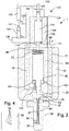
- Fig. 2 illustrates another exemplary embodiment of the fuel valve 1.
- the fuel valve 1 illustrated in Fig. 2 has an external housing 10 which at its rearmost end has a fuel inlet port 16 and a fuel outlet port 18.
- the inlet port 16 is to be connected to a source P of high pressure fuel such as fuel oil, heavy fuel oil or gaseous fuel such as natural gas from a fuel pump or from a common fuel rail.
- the outlet port 18 is to be connected to a return line to tank T.
- the fuel valve 1 may in a known manner be mounted in the cylinder cover of a large two-stroke diesel engine and be connected with a fuel pump (not shown).
- the fuel inlet port 16 is in flow connection with a duct 17.
- Duct 17 extends to the seat of a valve needle 20 that is axially displaceable in an axial bore in the valve housing 10.
- the valve needle 20 is biased to its seat 22 by a closing spring 23.
- the foremost part of the valve housing 10 holds a nozzle 30 that projects from the valve housing 10 and into the combustion chamber of the engine cylinder (not shown) when the fuel valve 1 is mounted on the cylinder cover.
- Fig. 2 shows the valve needle 20 resting on the valve seat 22. In this position the flow of fuel from the fuel oil inlet port 16 to the nozzle 30 is blocked. A chamber 25 above the valve seat 22 is connected to duct 17 to receive pressurized fuel.
- the valve needle 20 carries a foremost cut-off shaft 40 that is thinner than the rearmost section of the valve needle 20 and the cut-off shaft 40 projects into a central bore 33 in the nozzle 30.
- the cut-off shaft 40 is axially displaced in the central bore of the nozzle 30.
- the nozzle 30 is further provided with a plurality of nozzle holes 35 through which the fuel is injected into the combustion chamber from the central bore 33. Thus, during a fuel injection event a jet of fuel comes from the nozzle holes 35.
- the nozzle holes 35 are drilled into the nozzle.
- the centerline of each nozzle hole 35 may coincide roughly with the centerline of the central bore 33. However, the centerlines of the nozzle holes 35 do not have to coincide exactly with the centerline of the central bore 33.
- the cut-off shaft 40 is in an exemplary embodiment made as one piece of material with the valve needle 20.
- the cut-off shaft 40 is hollow and the hollow interior of the cut-off shaft 40 connects to the space downstream of the valve seat 22.
- the flow path 17 extends all the way from the fuel oil inlet 16 to the hollow interior of the cut-off shaft 40.
- a duct 19 is connected to the outlet port 18 and the duct 19 collects the return oil flow as will de explained in greater detail further hereafter.
- the foremost part of the cut-off shaft 40 is cylindrical and fits exactly into a central bore 33 in the nozzle 30.
- the angular position of the valve needle 20, and thereby the cut-off shaft 40 is fixed by a pin (not shown) that prevents the valve needle 20 from rotating relatively to the valve housing 10.
- the nozzle holes 35 are distributed over the nozzle 30 so as to distribute them with a space between them along the longitudinal extent of the nozzle, i.e. in an axial direction. In its lowermost position the cut off shaft 40 will always close the lowermost holes and can even have a small overlap improving the sealing conditions. Further, the nozzle holes 35 are spread radially and directed radially in different directions so as to cover a wide sector of the combustion chamber with fuel jets coming from the nozzle holes 35.
- the extent of the lift of the valve needle 20 and the cut-off shaft 40 determines how many of the nozzle holes 35 are open at a given point in time, and thus the extent of the lift of the valve needle 20 determines the flow area through which the fuel is atomized. The greater the lift the more nozzle holes 35 are open (until the lift has reached a stage where all nozzle holes 35 are open). Thus, the number of nozzle holes 35 that are in use during a fuel injection event can be controlled via the extent of the lift of the valve needle 20 and the cut-off shaft 40.
- a first group of nozzle holes 35 that are opened during the first part of the opening movement of the valve needle 20 have a relatively small diameter and the nozzle holes 35 that are opened in the following or second part of the opening movement of the valve needle 20 have a larger diameter than the nozzle holes 35 of the first group.
- a small lift of the valve needle 20 opens only the first group of nozzle holes 35 with the relatively small diameter, which creates a small flow through area which is good for injecting small amounts of fuel oil for pilot injection in gas operation of the engine and a larger lift of the valve needle 20 opens both the first group of nozzle holes 35 with the reduced diameter and the other nozzle holes 35 with the larger diameter which creates a large flow through area which is good for regular fuel oil injection in fuel oil operation of the engine.
- This embodiment is also particularly useful in connection with low load operation (in fuel oil operation) for injection the relatively small amounts of fuel oil that are injected at low load operation.
- the valve needle 20 includes an actuation section 93.
- the actuation section 93 can be an integral part of the valve needle 20 or be connected to the valve needle 20 (in the shown embodiment the actuation section is integral with the valve needle 20).
- the actuation section 93 is a substantially cylindrical section that is slidably received in an axial bore 95 in the valve housing 10 so that the actuation section 93 can act like a piston in the valve housing 10.
- a chamber 96 formed in the upper (or rear) part (upper as in the drawing) of the valve housing 10 is disposed above the actuation section 93 and a spring 23 for urging the valve needle 20 onto its seat 22 is received in the chamber 96 and acts on the top of the actuation section 93.
- a pressure chamber 100 for urging the valve needle 20 in the opening direction is located under the actuation section 93 and connected via bore 102 to duct 17. Pressure chamber 100 is therefore always pressurized when the fuel inlet port 16 is connected to the source of pressurized fuel (such as a fuel pump).
- the pressure in pressure chamber 100 acts with an effective surface A4 on the valve needle 20 to urge the latter in the opening direction.
- the combined hydraulic force on effective pressure surfaces A3 and A4 must be smaller than the combination of the hydraulic force on effective pressure area A5 and the force applied by the spring 96, otherwise the fuel valve will not be able to close.
- the actuation section 93 is connected to an electro hydraulic actuator 120 via a connection shaft 110.
- the electro hydraulic actuator 120 includes an actuator housing 122.
- An actuation piston 124 is slidably received in a cylindrical bore 126.
- the actuation piston 124 has also a reduced diameter section that is partially received in a reduced diameter section of the cylindrical bore 126.
- a first actuation chamber 128 is formed above the reduced diameter section of the actuation piston 124.
- the first actuation chamber 128 acts on the actuation piston 124 with an effective surface area A5 to urge the actuation piston in a downward direction (downward as in the figures).
- a second actuation chamber 130 is formed below the actuation piston 124.
- the second actuation chamber 130 acts on the actuation piston 124 with an effective surface area A6.
- the connection shaft 110 extends through the actuator housing 122 and to the second actuation chamber 130 and connects to the actuation piston 124.
- the first actuation chamber 128 is permanently connected to a source of pressure P1 (such as the fuel pump) via a conduit 133.
- the second actuation chamber 130 is connected to a proportional pilot valve 140 via a conduit 135.
- the proportional pilot valve 140 has two extreme positions and one middle position. In the first extreme position the proportional pilot valve 140 connects the second actuation chamber 130 to tank T. In the middle position in the proportional pilot 140 is closed and in the second extreme position the pilot valve 140 connects the second actuation chamber 130 to the source of pressure P1.
- the proportional pilot valve 140 can shift gradually between these three positions.
- the position of the proportional pilot valve is determined by an electronic control unit 150, such as electronic control unit of the engine.
- the electronic control unit 150 receives information about the position of the actuation piston via a position sensor 152 in the electro hydraulic actuator 120 to establish a closed loop control circuit for controlling the position of the electro-hydraulic actuator 120 and thereby the position and extent of lift of the valve needle 20.
- the electronic control unit 150 determines on the basis of various parameters such as engine load and speed the shape (rate shaping) and timing of the next injection event for a given cylinder. On the basis of the calculated profile for the rate shaping the electronic control unit 150 determines what the extent of the lift of the valve needle 20 has to be at a given point in time. The electronic control unit 150 instructs the electro-hydraulic actuator 120 to move to the determined position at a given point in time. When the valve lift is to be increased the electronic control unit 150 commands the proportional pilot valve 140 to connect the second actuation chamber 130 to the source of pressure P1 until the desired position is obtained.
- the actuation piston 124 the valve needle 20 moves up from an initial position (for example the closed position of the fuel valve) a distance determined by the electronic control unit 150 and the valve needle 20 is lifted from its seat 22 with the same distance as movement of the actuation piston 124 (in the initial position of the actuation piston 124 the valve needle 20 may rest on its seat 22).
- the extent of the valve needle lift as controlled by the electronic control unit 150 determines how many of the nozzle bores 35 are open during the fuel injection event or during a portion of the fuel injection event and the pressurized fuel is injected into the combustion chamber through the open holes 35.
- the electronic control unit 150 commands the electro hydraulic actuator 120 to follow the determined curve until the actuation piston 124 has returned to the initial position and the valve needle has returned to its seat 22 and the fuel injection event ends.
- the extent of the length of the upward movement of the electro-hydraulic actuator 120 from the initial position determines how many of the nozzle holes 35 are open at any point in time during the injection event and thereby the flow through area through the nozzle holes is determined.
- the number of nozzle holes 35 used during fuel injection event can thus be controlled individually for each fuel valve 1 and for each injection event and allows the number of nozzle holes 35 used during an injection event to be adapted to circumstances.
- the fuel valve according to the embodiment shown in Figure 2 includes an electro-hydraulic linear actuator 120,122,124,140,141, operably connected to said axially movable valve needle 20 for providing lift of the axially movable valve needle, whereby the linear actuator controls the magnitude of the lift of the axially movable valve needle 20 in response to a control signal.
- the electro-hydraulic actuator comprises an electrically operated actuator 141 acting on a proportional hydraulic valve 140 and the proportional hydraulic valve controls the flow to and from a linear hydraulic actuator 122,124,126,130 that is operably connected to the valve needle 20.
- One advantage of the teaching of this disclosure is that it provides for a fuel valve for a large two-stroke diesel engine that allows for and optimal number of nozzle bores to be open during an injection event. It is another advantage of the fuel valve that it allows for precise control of a fuel injection event. It is another advantage of the present fuel valve that it can be used for pilot injection during gaseous fuel operation and for regular fuel injection with fuel oil or heavy fuel oil. It is another advantage of the present disclosure that it provides for a fuel valve that allows small diameter nozzle bores to be used with pilot injection during gaseous fuel operation and large diameter nozzle holes to be used when operating on fuel oil or heavy fuel oil.
Claims (12)
- Kraftstoffventil (1) zum Einspritzen von Kraftstoff in die Verbrennungskammer eines großen Zweitakt-Dieselmotors, wobei das Kraftstoffventil Folgendes umfasst:ein Kraftstoffventilgehäuse (10),eine längliche Düse (30) mit einer zentralen Bohrung (33) und einer geschlossenen Vorderseite,eine Hochdruck-Kraftstoffeinlassöffnung (16) zur Verbindung mit einer Hochdruckkraftstoffquelle (P),eine Leitung (17), die die Hochdruck-Kraftstoffeinlassöffnung (16) mit der Düse (30) verbindet,eine federnd vorgespannte und axial bewegliche Ventilnadel (20), die mit einem Ventilsitz (22) zusammenwirkt und konfiguriert ist, den Kraftstoffstrom von der Hochdruckkraftstoff-Einlassöffnung (16) zu der Düse (30) zu steuern, wodurch ein Hub der axial beweglichen Ventilnadel (20) einen Strom von der Hochdruck-Kraftstoffeinlassöffnung zur Düse (30) zu ermöglicht,eine Kammer (25) oberhalb des Ventilsitzes (22), die mit der Leitung (17) verbunden ist, um unter Druck stehenden Kraftstoff aufzunehmen,mehrere Düsenlöcher (35), die axial und radial über der Düse (30) verteilt sind,eine Absperrwelle (40), die sich gemeinsam mit der Ventilnadel (20) bewegt und axial verschiebbar in der zentralen Bohrung (33) in der Düse (30) zum Öffnen und Schließen der Düsenlöcher (35) aufgenommen ist,wobei die mehreren Düsenlöcher (35) axial derart verteilt sind, dass die Anzahl der Düsenlöcher, die offen sind, mit zunehmendem Hub der Ventilnadel (20) und der Absperrwelle (40) zunimmt, sodass die Höhe des Hubs der axial beweglichen Ventilnadel (20) bestimmt, wie viele Düsenlöcher offen sind, und dadurch den Strömungsbereich bestimmt, undgekennzeichnet durcheinen elektrohydraulischen linearen Aktuator (43, 46, 53, 70; 120), der mit der axial beweglichen Ventilnadel betrieblich verbunden ist, um einen Hub der axial beweglichen Ventilnadel zu liefern, wobei der elektrohydraulische lineare Aktuator die Größe des Hubs der axial beweglichen Ventilnadel (20) als Reaktion auf ein Steuersignal steuert, und dadurch,dass der elektrohydraulische lineare Aktuator (43, 46, 53, 70; 120) einen hydraulischen linearen Aktuator umfasst, der mit der Ventilnadel (20) betrieblich verbunden ist, ein elektrisch betriebener Aktuator (85, 141) auf ein proportionales hydraulisches Ventil (53, 57, 58, 59, 140) wirkt und das proportionale hydraulische Ventil den Strom zu und von dem linearen hydraulischen Aktuator (43, 46, 53, 70; 122, 124, 126, 130) steuert.
- Kraftstoffventil (1) nach Anspruch 1, wobei der elektrohydraulische lineare Aktuator (43, 46, 53, 70) mindestens teilweise in die axial bewegliche Ventilnadel (20) integriert ist.
- Kraftstoffventil (1) nach Anspruch 2, wobei der lineare Aktuator einen elektrischen Linearmotor (85) umfasst, der betrieblich mit einem Betätigungsschieber (53) gekoppelt ist, der in einer axialen Bohrung (52) in einem Betätigungsabschnitt (43) der axial beweglichen Ventilnadel (20) aufgenommen ist, und der Betätigungsschieber (53) Teil des hydraulischen Ventils und konfiguriert ist, den Fluidstrom zu und von dem linearen hydraulischen Aktuator zu steuern.
- Kraftstoffventil (1) nach Anspruch 3, wobei das Gehäuse des linearen Aktuators starr mit dem Kraftstoffventilgehäuse (10) verbunden ist und eine Ausgangswelle des Linearmotors mit dem Betätigungsschieber (53) betrieblich verbunden ist.
- Kraftstoffventil (1) nach Anspruch 3 oder 4, ferner umfassend eine Druckkammer (46) in dem Ventilgehäuse (10), die über der axial beweglichen Ventilnadel angeordnet ist, um die axial bewegliche Ventilnadel (20) im druckbeaufschlagten Zustand in Richtung des Ventilsitzes (22) zu pressen, wobei der Betätigungsschieber (53) konfiguriert ist, entweder die Druckkammer mit der Hochdruck-Kraftstoffeinlassöffnung (16) zu verbinden oder die Druckkammer mit dem Ablass zu verbinden oder die Druckkammer zu verschließen, abhängig von der Position des Betätigungsschiebers relativ zu der axial beweglichen Ventilnadel.
- Kraftstoffventil (1) nach einem der Ansprüche 3 bis 5, wobei der Betätigungsschieber (53) mit mehreren Öffnungen in der axial beweglichen Ventilnadel (20) zusammenwirkt, wobei die Öffnungen die Hochdruck-Kraftstoffeinlassöffnung (16) mit dem Ablass bzw. mit der Druckkammer verbinden.
- Kraftstoffventil (1) nach einem der Ansprüche 3 bis 6, wobei die Öffnungen und der Betätigungsschieber derart konfiguriert sind, dass die axial bewegliche Ventilnadel der axialen Bewegung des Betätigungsschiebers relativ zu dem Ventilgehäuse (10) folgt.
- Kraftstoffventil (1) nach einem der Ansprüche 1 bis 7, wobei der Linearmotor (85, 141) ein Ausgangswellen-Positionssignal liefert, oder wobei ein Positionssensor mit einer Ausgangswelle des Linearmotors oder mit dem Betätigungsschieber (53) gekoppelt ist.
- Kraftstoffventil (1) nach einem der Ansprüche 1 bis 7, wobei der lineare Aktuator ein Ausgangswellen-Positionssignal liefert, oder wobei ein Positionssensor mit einer Ausgangswelle des linearen Aktuators oder mit dem Betätigungsschieber gekoppelt ist.
- Kraftstoffventil (1) nach einem der Ansprüche 1 bis 9, wobei das Innere der Absperrwelle (40) hohl ist und das hohle Innere mit der Einlassöffnung (16) des Kraftstoffventils (1) verbunden ist, wenn die Ventilnadel (20) von ihrem Sitz (22) angehoben wird.
- Kraftstoffventil (1) nach einem der Ansprüche 1 bis 10, wobei der Strömungsbereich durch die Düsenlöcher durch die Höhe des Hubs der Ventilnadel bestimmt wird.
- Kraftstoffventil (1) nach Anspruch 1, ferner umfassend:eine Druckkammer (46) in dem Ventilgehäuse (10), die über der axial beweglichen Ventilnadel angeordnet ist, um die axial bewegliche Ventilnadel im druckbeaufschlagten Zustand in Richtung des Ventilsitzes zu pressen,wobei der elektrische Linearmotor (85) betrieblich mit einem Betätigungsschieber (53) gekoppelt ist, der in einer axialen Bohrung (52) in der axial beweglichen Ventilnadel (20) aufgenommen ist, wobei der Betätigungsschieber (53) konfiguriert ist, entweder die Druckkammer (46) mit der Hochdruck-Kraftstoffeinlassöffnung (16) zu verbinden oder die Druckkammer (46) zum Ablass zu verbinden oder die Druckkammer (46) zu verschließen, abhängig von der Position des Betätigungsschiebers (53) relativ zu der axial beweglichen Ventilnadel (20).
Applications Claiming Priority (1)
| Application Number | Priority Date | Filing Date | Title |
|---|---|---|---|
| DKPA201100480A DK177420B1 (en) | 2011-06-27 | 2011-06-27 | Fuel valve for large turbocharged two-stroke diesel engines |
Publications (2)
| Publication Number | Publication Date |
|---|---|
| EP2543870A1 EP2543870A1 (de) | 2013-01-09 |
| EP2543870B1 true EP2543870B1 (de) | 2019-07-24 |
Family
ID=46384217
Family Applications (1)
| Application Number | Title | Priority Date | Filing Date |
|---|---|---|---|
| EP12173372.9A Active EP2543870B1 (de) | 2011-06-27 | 2012-06-25 | Einspritzdüse für Zweitakt-Dieselmotoren mit großem Hubraum und Turboaufladung |
Country Status (5)
| Country | Link |
|---|---|
| EP (1) | EP2543870B1 (de) |
| JP (1) | JP2013011273A (de) |
| KR (1) | KR101318565B1 (de) |
| CN (1) | CN102852685B (de) |
| DK (1) | DK177420B1 (de) |
Families Citing this family (6)
| Publication number | Priority date | Publication date | Assignee | Title |
|---|---|---|---|---|
| DE102013001098B3 (de) * | 2013-01-23 | 2014-07-03 | L'orange Gmbh | Kraftstoffinjektor |
| DK178519B1 (en) | 2014-10-17 | 2016-05-09 | Man Diesel & Turbo Deutschland | A fuel valve for injecting gaseous fuel into a combustion chamber of a self-igniting internal combustion engine and method |
| DK178655B1 (en) * | 2015-03-20 | 2016-10-17 | Man Diesel & Turbo Filial Af Man Diesel & Turbo Se Tyskland | Fuel valve for injecting fuel into a combustion chamber of a large self-igniting turbocharged two-stroke internal combustion engine |
| DK178656B1 (en) * | 2015-03-20 | 2016-10-17 | Man Diesel & Turbo Filial Af Man Diesel & Turbo Se Tyskland | Fuel valve for injecting a low flashpoint fuel into a combustion chamber of a large self-igniting turbocharged two-stroke internal combustion engine |
| DE102017122117A1 (de) * | 2017-09-25 | 2019-03-28 | Man Diesel & Turbo Se | Einspritzdüse für einen Dual-Fuel-Motor und Dual-Fuel-Motor |
| CN114165376B (zh) * | 2021-12-17 | 2023-06-30 | 中国船舶集团有限公司第七一一研究所 | 喷油器以及喷油方法 |
Family Cites Families (14)
| Publication number | Priority date | Publication date | Assignee | Title |
|---|---|---|---|---|
| US5152271A (en) * | 1985-07-15 | 1992-10-06 | Osamu Matsumura | Fuel injection apparatus |
| KR100370453B1 (ko) * | 1994-02-15 | 2003-04-10 | 인벤트 엔지니어링 피티와이. 엘티디. | 유압으로작동되는전자연료분사장치 |
| DK174240B1 (da) * | 1994-03-08 | 2002-10-14 | Man B & W Diesel As | Brændselsventil og højtryksgasmotor med en sådan ventil |
| DE4417950C1 (de) * | 1994-05-21 | 1995-05-11 | Mtu Friedrichshafen Gmbh | Einspritzsystem |
| JPH08193560A (ja) * | 1994-11-15 | 1996-07-30 | Zexel Corp | 可変噴孔型燃料噴射ノズル |
| JP3700981B2 (ja) * | 1995-08-29 | 2005-09-28 | いすゞ自動車株式会社 | 蓄圧式燃料噴射装置 |
| JPH09303234A (ja) * | 1996-05-10 | 1997-11-25 | Isuzu Motors Ltd | 燃料噴射ノズル |
| DE19755062A1 (de) * | 1997-12-11 | 1999-06-17 | Bosch Gmbh Robert | Kraftstoffeinspritzventil für Brennkraftmaschinen |
| JP3823540B2 (ja) * | 1998-06-05 | 2006-09-20 | 株式会社デンソー | 内燃機関用燃料噴射弁 |
| DE10100512A1 (de) | 2000-02-07 | 2001-08-09 | Bosch Gmbh Robert | Einspritzdüse |
| US6439483B2 (en) * | 2000-02-10 | 2002-08-27 | Andrew E. Meyer | Variable orifice electronically controlled common rail injector (VOECRRI) |
| JP2002227747A (ja) | 2001-01-31 | 2002-08-14 | Denso Corp | 制御弁およびそれを備えた燃料噴射弁 |
| DE102005009148A1 (de) * | 2005-03-01 | 2006-09-07 | Robert Bosch Gmbh | Kraftstoffinjektor mit direktgesteuertem Einspritzventilglied mit Doppelsitz |
| KR101043745B1 (ko) * | 2006-12-15 | 2011-06-22 | 맨 디젤 앤드 터보 필리얼 아프 맨 디젤 앤드 터보 에스이 티스크랜드 | 내연기관용 연료분사기 |
-
2011
- 2011-06-27 DK DKPA201100480A patent/DK177420B1/en active
-
2012
- 2012-06-15 JP JP2012135432A patent/JP2013011273A/ja active Pending
- 2012-06-25 EP EP12173372.9A patent/EP2543870B1/de active Active
- 2012-06-26 KR KR1020120068521A patent/KR101318565B1/ko active IP Right Grant
- 2012-06-27 CN CN201210217323.7A patent/CN102852685B/zh active Active
Non-Patent Citations (1)
| Title |
|---|
| None * |
Also Published As
| Publication number | Publication date |
|---|---|
| KR20130001696A (ko) | 2013-01-04 |
| DK201100480A (en) | 2012-12-28 |
| EP2543870A1 (de) | 2013-01-09 |
| JP2013011273A (ja) | 2013-01-17 |
| DK177420B1 (en) | 2013-04-22 |
| CN102852685A (zh) | 2013-01-02 |
| CN102852685B (zh) | 2015-04-22 |
| KR101318565B1 (ko) | 2013-10-16 |
Similar Documents
| Publication | Publication Date | Title |
|---|---|---|
| EP2543870B1 (de) | Einspritzdüse für Zweitakt-Dieselmotoren mit großem Hubraum und Turboaufladung | |
| US20130001327A1 (en) | High-pressure fuel injection valve for an internal combustion engine | |
| CN102691605B (zh) | 用于大型柴油发动机的电控燃料喷射器 | |
| RU2459107C2 (ru) | Топливный инжектор (варианты) | |
| CN101849098B (zh) | 喷射系统和用于制造喷射系统的方法 | |
| EP3406891B1 (de) | Einspritzdüse für zweitakt-dieselmotoren mit grossem hubraum und turboaufladung | |
| JP2013011273A5 (de) | ||
| EP3183450B1 (de) | Steuerventilanordnung | |
| CN107690509B (zh) | 用于发动机阀的气动促动器 | |
| JPH0768962B2 (ja) | ロードセンシング機能付き方向切換弁 | |
| EP2386745B1 (de) | Kraftstoffinjektor für Verbrennungsmotoren | |
| US9879644B2 (en) | Fuel injector with variable area pintle nozzle | |
| CN103470385B (zh) | 低速船用柴油机高压共轨燃油喷射控制系统 | |
| US20070235554A1 (en) | Dual stroke injector using SMA | |
| JP3974614B2 (ja) | 2つの圧力媒体衝撃式集合機械と1つの圧力媒体源とのタイミングをずらした接続を制御するための装置 | |
| EP1633972B1 (de) | Anordnung in einer kraftstoffeinspritzvorrichtung | |
| US6568360B2 (en) | Electrohydraulic device for operating the valves of a combustion engine | |
| EP2815088B1 (de) | Hydraulische ventilanordnung zur steuerbaren betätigung eines gaswechselventils eines hubkolben-verbrennungsmotors | |
| EP2083165A1 (de) | Einspritzdüse | |
| JPH084625A (ja) | 噴口面積可変型燃料噴射ノズル | |
| JPS6179857A (ja) | 内燃機関の燃料噴射装置 |
Legal Events
| Date | Code | Title | Description |
|---|---|---|---|
| PUAI | Public reference made under article 153(3) epc to a published international application that has entered the european phase |
Free format text: ORIGINAL CODE: 0009012 |
|
| AK | Designated contracting states |
Kind code of ref document: A1 Designated state(s): AL AT BE BG CH CY CZ DE DK EE ES FI FR GB GR HR HU IE IS IT LI LT LU LV MC MK MT NL NO PL PT RO RS SE SI SK SM TR |
|
| AX | Request for extension of the european patent |
Extension state: BA ME |
|
| 17P | Request for examination filed |
Effective date: 20130709 |
|
| RBV | Designated contracting states (corrected) |
Designated state(s): AL AT BE BG CH CY CZ DE DK EE ES FI FR GB GR HR HU IE IS IT LI LT LU LV MC MK MT NL NO PL PT RO RS SE SI SK SM TR |
|
| 17Q | First examination report despatched |
Effective date: 20160616 |
|
| STAA | Information on the status of an ep patent application or granted ep patent |
Free format text: STATUS: EXAMINATION IS IN PROGRESS |
|
| GRAP | Despatch of communication of intention to grant a patent |
Free format text: ORIGINAL CODE: EPIDOSNIGR1 |
|
| STAA | Information on the status of an ep patent application or granted ep patent |
Free format text: STATUS: GRANT OF PATENT IS INTENDED |
|
| INTG | Intention to grant announced |
Effective date: 20190204 |
|
| RAP1 | Party data changed (applicant data changed or rights of an application transferred) |
Owner name: MAN ENERGY SOLUTIONS, FILIAL AF MAN ENERGY SOLUTIO |
|
| GRAS | Grant fee paid |
Free format text: ORIGINAL CODE: EPIDOSNIGR3 |
|
| GRAA | (expected) grant |
Free format text: ORIGINAL CODE: 0009210 |
|
| STAA | Information on the status of an ep patent application or granted ep patent |
Free format text: STATUS: THE PATENT HAS BEEN GRANTED |
|
| AK | Designated contracting states |
Kind code of ref document: B1 Designated state(s): AL AT BE BG CH CY CZ DE DK EE ES FI FR GB GR HR HU IE IS IT LI LT LU LV MC MK MT NL NO PL PT RO RS SE SI SK SM TR |
|
| REG | Reference to a national code |
Ref country code: GB Ref legal event code: FG4D |
|
| REG | Reference to a national code |
Ref country code: CH Ref legal event code: EP |
|
| REG | Reference to a national code |
Ref country code: DE Ref legal event code: R096 Ref document number: 602012062204 Country of ref document: DE |
|
| REG | Reference to a national code |
Ref country code: AT Ref legal event code: REF Ref document number: 1158489 Country of ref document: AT Kind code of ref document: T Effective date: 20190815 |
|
| REG | Reference to a national code |
Ref country code: IE Ref legal event code: FG4D |
|
| REG | Reference to a national code |
Ref country code: NL Ref legal event code: FP |
|
| REG | Reference to a national code |
Ref country code: CH Ref legal event code: NV Representative=s name: MICHELI AND CIE SA, CH |
|
| REG | Reference to a national code |
Ref country code: LT Ref legal event code: MG4D |
|
| REG | Reference to a national code |
Ref country code: AT Ref legal event code: MK05 Ref document number: 1158489 Country of ref document: AT Kind code of ref document: T Effective date: 20190724 |
|
| PG25 | Lapsed in a contracting state [announced via postgrant information from national office to epo] |
Ref country code: NO Free format text: LAPSE BECAUSE OF FAILURE TO SUBMIT A TRANSLATION OF THE DESCRIPTION OR TO PAY THE FEE WITHIN THE PRESCRIBED TIME-LIMIT Effective date: 20191024 Ref country code: BG Free format text: LAPSE BECAUSE OF FAILURE TO SUBMIT A TRANSLATION OF THE DESCRIPTION OR TO PAY THE FEE WITHIN THE PRESCRIBED TIME-LIMIT Effective date: 20191024 Ref country code: PT Free format text: LAPSE BECAUSE OF FAILURE TO SUBMIT A TRANSLATION OF THE DESCRIPTION OR TO PAY THE FEE WITHIN THE PRESCRIBED TIME-LIMIT Effective date: 20191125 Ref country code: HR Free format text: LAPSE BECAUSE OF FAILURE TO SUBMIT A TRANSLATION OF THE DESCRIPTION OR TO PAY THE FEE WITHIN THE PRESCRIBED TIME-LIMIT Effective date: 20190724 Ref country code: LT Free format text: LAPSE BECAUSE OF FAILURE TO SUBMIT A TRANSLATION OF THE DESCRIPTION OR TO PAY THE FEE WITHIN THE PRESCRIBED TIME-LIMIT Effective date: 20190724 Ref country code: AT Free format text: LAPSE BECAUSE OF FAILURE TO SUBMIT A TRANSLATION OF THE DESCRIPTION OR TO PAY THE FEE WITHIN THE PRESCRIBED TIME-LIMIT Effective date: 20190724 Ref country code: SE Free format text: LAPSE BECAUSE OF FAILURE TO SUBMIT A TRANSLATION OF THE DESCRIPTION OR TO PAY THE FEE WITHIN THE PRESCRIBED TIME-LIMIT Effective date: 20190724 |
|
| PG25 | Lapsed in a contracting state [announced via postgrant information from national office to epo] |
Ref country code: AL Free format text: LAPSE BECAUSE OF FAILURE TO SUBMIT A TRANSLATION OF THE DESCRIPTION OR TO PAY THE FEE WITHIN THE PRESCRIBED TIME-LIMIT Effective date: 20190724 Ref country code: GR Free format text: LAPSE BECAUSE OF FAILURE TO SUBMIT A TRANSLATION OF THE DESCRIPTION OR TO PAY THE FEE WITHIN THE PRESCRIBED TIME-LIMIT Effective date: 20191025 Ref country code: IS Free format text: LAPSE BECAUSE OF FAILURE TO SUBMIT A TRANSLATION OF THE DESCRIPTION OR TO PAY THE FEE WITHIN THE PRESCRIBED TIME-LIMIT Effective date: 20191124 Ref country code: RS Free format text: LAPSE BECAUSE OF FAILURE TO SUBMIT A TRANSLATION OF THE DESCRIPTION OR TO PAY THE FEE WITHIN THE PRESCRIBED TIME-LIMIT Effective date: 20190724 Ref country code: ES Free format text: LAPSE BECAUSE OF FAILURE TO SUBMIT A TRANSLATION OF THE DESCRIPTION OR TO PAY THE FEE WITHIN THE PRESCRIBED TIME-LIMIT Effective date: 20190724 Ref country code: LV Free format text: LAPSE BECAUSE OF FAILURE TO SUBMIT A TRANSLATION OF THE DESCRIPTION OR TO PAY THE FEE WITHIN THE PRESCRIBED TIME-LIMIT Effective date: 20190724 |
|
| PG25 | Lapsed in a contracting state [announced via postgrant information from national office to epo] |
Ref country code: TR Free format text: LAPSE BECAUSE OF FAILURE TO SUBMIT A TRANSLATION OF THE DESCRIPTION OR TO PAY THE FEE WITHIN THE PRESCRIBED TIME-LIMIT Effective date: 20190724 |
|
| PG25 | Lapsed in a contracting state [announced via postgrant information from national office to epo] |
Ref country code: RO Free format text: LAPSE BECAUSE OF FAILURE TO SUBMIT A TRANSLATION OF THE DESCRIPTION OR TO PAY THE FEE WITHIN THE PRESCRIBED TIME-LIMIT Effective date: 20190724 Ref country code: EE Free format text: LAPSE BECAUSE OF FAILURE TO SUBMIT A TRANSLATION OF THE DESCRIPTION OR TO PAY THE FEE WITHIN THE PRESCRIBED TIME-LIMIT Effective date: 20190724 Ref country code: DK Free format text: LAPSE BECAUSE OF FAILURE TO SUBMIT A TRANSLATION OF THE DESCRIPTION OR TO PAY THE FEE WITHIN THE PRESCRIBED TIME-LIMIT Effective date: 20190724 Ref country code: PL Free format text: LAPSE BECAUSE OF FAILURE TO SUBMIT A TRANSLATION OF THE DESCRIPTION OR TO PAY THE FEE WITHIN THE PRESCRIBED TIME-LIMIT Effective date: 20190724 |
|
| PG25 | Lapsed in a contracting state [announced via postgrant information from national office to epo] |
Ref country code: CZ Free format text: LAPSE BECAUSE OF FAILURE TO SUBMIT A TRANSLATION OF THE DESCRIPTION OR TO PAY THE FEE WITHIN THE PRESCRIBED TIME-LIMIT Effective date: 20190724 Ref country code: SK Free format text: LAPSE BECAUSE OF FAILURE TO SUBMIT A TRANSLATION OF THE DESCRIPTION OR TO PAY THE FEE WITHIN THE PRESCRIBED TIME-LIMIT Effective date: 20190724 Ref country code: IS Free format text: LAPSE BECAUSE OF FAILURE TO SUBMIT A TRANSLATION OF THE DESCRIPTION OR TO PAY THE FEE WITHIN THE PRESCRIBED TIME-LIMIT Effective date: 20200224 Ref country code: SM Free format text: LAPSE BECAUSE OF FAILURE TO SUBMIT A TRANSLATION OF THE DESCRIPTION OR TO PAY THE FEE WITHIN THE PRESCRIBED TIME-LIMIT Effective date: 20190724 |
|
| REG | Reference to a national code |
Ref country code: DE Ref legal event code: R097 Ref document number: 602012062204 Country of ref document: DE |
|
| PLBE | No opposition filed within time limit |
Free format text: ORIGINAL CODE: 0009261 |
|
| STAA | Information on the status of an ep patent application or granted ep patent |
Free format text: STATUS: NO OPPOSITION FILED WITHIN TIME LIMIT |
|
| PG2D | Information on lapse in contracting state deleted |
Ref country code: IS |
|
| 26N | No opposition filed |
Effective date: 20200603 |
|
| PG25 | Lapsed in a contracting state [announced via postgrant information from national office to epo] |
Ref country code: SI Free format text: LAPSE BECAUSE OF FAILURE TO SUBMIT A TRANSLATION OF THE DESCRIPTION OR TO PAY THE FEE WITHIN THE PRESCRIBED TIME-LIMIT Effective date: 20190724 |
|
| PG25 | Lapsed in a contracting state [announced via postgrant information from national office to epo] |
Ref country code: MC Free format text: LAPSE BECAUSE OF FAILURE TO SUBMIT A TRANSLATION OF THE DESCRIPTION OR TO PAY THE FEE WITHIN THE PRESCRIBED TIME-LIMIT Effective date: 20190724 |
|
| PG25 | Lapsed in a contracting state [announced via postgrant information from national office to epo] |
Ref country code: LU Free format text: LAPSE BECAUSE OF NON-PAYMENT OF DUE FEES Effective date: 20200625 |
|
| REG | Reference to a national code |
Ref country code: BE Ref legal event code: MM Effective date: 20200630 |
|
| PG25 | Lapsed in a contracting state [announced via postgrant information from national office to epo] |
Ref country code: IE Free format text: LAPSE BECAUSE OF NON-PAYMENT OF DUE FEES Effective date: 20200625 |
|
| PG25 | Lapsed in a contracting state [announced via postgrant information from national office to epo] |
Ref country code: BE Free format text: LAPSE BECAUSE OF NON-PAYMENT OF DUE FEES Effective date: 20200630 |
|
| PG25 | Lapsed in a contracting state [announced via postgrant information from national office to epo] |
Ref country code: MT Free format text: LAPSE BECAUSE OF FAILURE TO SUBMIT A TRANSLATION OF THE DESCRIPTION OR TO PAY THE FEE WITHIN THE PRESCRIBED TIME-LIMIT Effective date: 20190724 Ref country code: CY Free format text: LAPSE BECAUSE OF FAILURE TO SUBMIT A TRANSLATION OF THE DESCRIPTION OR TO PAY THE FEE WITHIN THE PRESCRIBED TIME-LIMIT Effective date: 20190724 |
|
| PG25 | Lapsed in a contracting state [announced via postgrant information from national office to epo] |
Ref country code: MK Free format text: LAPSE BECAUSE OF FAILURE TO SUBMIT A TRANSLATION OF THE DESCRIPTION OR TO PAY THE FEE WITHIN THE PRESCRIBED TIME-LIMIT Effective date: 20190724 |
|
| PGFP | Annual fee paid to national office [announced via postgrant information from national office to epo] |
Ref country code: NL Payment date: 20230620 Year of fee payment: 12 Ref country code: FR Payment date: 20230627 Year of fee payment: 12 Ref country code: DE Payment date: 20230620 Year of fee payment: 12 |
|
| PGFP | Annual fee paid to national office [announced via postgrant information from national office to epo] |
Ref country code: FI Payment date: 20230621 Year of fee payment: 12 |
|
| PGFP | Annual fee paid to national office [announced via postgrant information from national office to epo] |
Ref country code: IT Payment date: 20230623 Year of fee payment: 12 Ref country code: GB Payment date: 20230622 Year of fee payment: 12 Ref country code: CH Payment date: 20230702 Year of fee payment: 12 |