EP2543591A2 - System for electric motorisation of a wheel - Google Patents
System for electric motorisation of a wheel Download PDFInfo
- Publication number
- EP2543591A2 EP2543591A2 EP12185383A EP12185383A EP2543591A2 EP 2543591 A2 EP2543591 A2 EP 2543591A2 EP 12185383 A EP12185383 A EP 12185383A EP 12185383 A EP12185383 A EP 12185383A EP 2543591 A2 EP2543591 A2 EP 2543591A2
- Authority
- EP
- European Patent Office
- Prior art keywords
- wheel
- engine block
- motor
- drive
- carried
- Prior art date
- Legal status (The legal status is an assumption and is not a legal conclusion. Google has not performed a legal analysis and makes no representation as to the accuracy of the status listed.)
- Granted
Links
- 230000009467 reduction Effects 0.000 claims abstract description 27
- 238000006073 displacement reaction Methods 0.000 claims description 19
- 239000000725 suspension Substances 0.000 claims description 13
- 230000005540 biological transmission Effects 0.000 claims description 8
- 238000005096 rolling process Methods 0.000 claims description 6
- 230000001360 synchronised effect Effects 0.000 abstract description 2
- 238000013016 damping Methods 0.000 description 4
- 210000002414 leg Anatomy 0.000 description 4
- 230000035939 shock Effects 0.000 description 3
- 239000012080 ambient air Substances 0.000 description 2
- 230000000694 effects Effects 0.000 description 2
- 238000005461 lubrication Methods 0.000 description 2
- 230000001105 regulatory effect Effects 0.000 description 2
- 240000008042 Zea mays Species 0.000 description 1
- 239000006096 absorbing agent Substances 0.000 description 1
- 230000001133 acceleration Effects 0.000 description 1
- 230000009471 action Effects 0.000 description 1
- 230000006978 adaptation Effects 0.000 description 1
- 230000008033 biological extinction Effects 0.000 description 1
- 230000008859 change Effects 0.000 description 1
- 239000003638 chemical reducing agent Substances 0.000 description 1
- 230000000295 complement effect Effects 0.000 description 1
- 230000001276 controlling effect Effects 0.000 description 1
- 238000001816 cooling Methods 0.000 description 1
- 230000001419 dependent effect Effects 0.000 description 1
- 239000003344 environmental pollutant Substances 0.000 description 1
- 239000000446 fuel Substances 0.000 description 1
- 230000010354 integration Effects 0.000 description 1
- 210000003127 knee Anatomy 0.000 description 1
- 230000007246 mechanism Effects 0.000 description 1
- 210000000056 organ Anatomy 0.000 description 1
- 231100000719 pollutant Toxicity 0.000 description 1
- 230000007704 transition Effects 0.000 description 1
Images


Classifications
-
- B—PERFORMING OPERATIONS; TRANSPORTING
- B64—AIRCRAFT; AVIATION; COSMONAUTICS
- B64C—AEROPLANES; HELICOPTERS
- B64C25/00—Alighting gear
- B64C25/32—Alighting gear characterised by elements which contact the ground or similar surface
- B64C25/405—Powered wheels, e.g. for taxing
-
- Y—GENERAL TAGGING OF NEW TECHNOLOGICAL DEVELOPMENTS; GENERAL TAGGING OF CROSS-SECTIONAL TECHNOLOGIES SPANNING OVER SEVERAL SECTIONS OF THE IPC; TECHNICAL SUBJECTS COVERED BY FORMER USPC CROSS-REFERENCE ART COLLECTIONS [XRACs] AND DIGESTS
- Y02—TECHNOLOGIES OR APPLICATIONS FOR MITIGATION OR ADAPTATION AGAINST CLIMATE CHANGE
- Y02T—CLIMATE CHANGE MITIGATION TECHNOLOGIES RELATED TO TRANSPORTATION
- Y02T50/00—Aeronautics or air transport
- Y02T50/80—Energy efficient operational measures, e.g. ground operations or mission management
Definitions
- the present invention relates to a motorization system of a wheel of an aircraft, for example applied to an aircraft, for the circulation of the latter on the ground.
- a motorization system of a wheel associated with a suspension of the type comprising an engine block, a drive member integral with the wheel, and a clutch device connecting the output shaft of the engine block to the driving member.
- the present invention aims to achieve a motorization system that can easily withstand the deformation of the strut and the wheel itself.
- the engine block comprises an electric motor and is carried by an unsprung portion of a suspension strut.
- the entire motorization system is carried by the unsprung portion of the strut: on the one hand, the drive member by the wheel, and, on the other hand, the engine block and the device clutch through the axle beam, which facilitates the integration of the drive system.
- the shock absorber of the suspension it is not necessary to take into account the movement of the shock absorber of the suspension for the connection of the output shaft of the engine block to the drive member.
- the engine block is carried by an axle cross member of the wheel.
- the engine block comprises a reduction system connecting the output shaft of the motor to the drive member.
- the reduction system is integral with the engine.
- the clutch device is shaped so as to move the engine block in an engaged position in which the block is connected to the drive member, and a disengaged position in which the block is separated.
- the clutch device is shaped so that the engine block is pivotally mounted relative to the cross axle, along a horizontal axis.
- the clutch device comprises a displacement system for moving the engine block from one to the other of its two positions engaged and disengaged.
- the displacement system is adapted to apply to the engine block a force greater than a limit value necessary for the engine block remains in the engaged position.
- the displacement system comprises a motor element.
- the driving element is formed by a jack.
- one end of the jack is rotatably mounted on a fastener integral with the cross member, the other end of the jack being rotatably mounted with two connecting rods, one of these rods being rotatably mounted on the piece. fixing, the other connecting rod being rotatably mounted on the engine block.
- the engine block is arranged to be naturally driven by its own weight in the disengaged position.
- the clutch device comprises a guided connecting rod for defining the disengaged position of the movement of the engine block.
- the guided rod comprises a rod, said rod being, on the one hand, rotatably mounted on a fastener integral with the cross member, and, on the other hand, slidably mounted relative to a pivot carried by the engine block.
- a damping unit for absorbing the shocks of the engine block is disposed between the pivot and the free end of the rod.
- the damping unit is formed by a fixed abutment fixed to the free end of the rod, a movable abutment slidably mounted along the rod between the free end of the rod and the pivot, and an elastic member disposed between the two stops so that the elastic member is prestressed between the two stops when the engine block is not in the disengaged position.
- the drive member is a ring gear carried by the rim of the wheel, and adapted to receive in meshing the output gear of the engine block when the latter is in its engaged position.
- the geared position of the output gear is defined by two bearing lips carried by the ring gear and adapted to receive rolling without sliding two tracks carried by the pinion.
- the invention also relates to a set of two motorization systems according to the first aspect of the invention, the two engine blocks being integral with each other and fixed to the unsprung portion of the suspension strut common to both wheels. .
- the two engine blocks are arranged between the two wheels.
- the two engine blocks are arranged behind a suspension strut carrying the cross axle.
- the set of two drive systems comprises only one clutch device common to both systems.
- Such a motorization system or such a set of two motorization systems, as appropriate, is advantageously used for the motorization of a main landing gear of an aircraft.
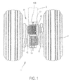
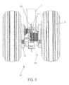
- the figures 1 and 8 represent a main landing gear 1, 101 of an aircraft, comprising two coaxial wheels 2, and a suspension strut 3 carrying these two wheels 2.
- This landing gear 1, 101 also comprises a set of two drive systems wheel, that is to say, a wheel system 2.
- the fact of having a motorization system for each wheel 2 eliminates the need to add a differential and allows to adjust the speed of the wheels 2 during turns. This also makes it possible to partially balance the forces on the suspension and on the motorization system of the wheel. Moreover, this distributes efforts on all the tires so that homogenizes and limits their wear.
- a motorization system comprises a motor unit 4, 104 which is integral with the axle beam 5 of the wheel 2, a drive member 6 which is integral with the wheel 2, and a device clutch 7 which connects the output shaft 8 of the engine block 4, 104 to the drive member 6. More specifically, the engine block 4, 104 and the clutch device 7 are arranged at the outside the crossbar 5 and are connected to each other while being cantilevered with respect to this cross.
- the entire motorization system is carried by the unsprung portion 3a of the strut 3: the engine block 4, 104 and the clutch device 7 are carried by the cross axle 5, and the driving member 6 is carried by the wheel 2.
- the drive member 6 secured to the wheel 2 is formed by a ring gear 6 carried by the rim 9 of the wheel 2, this ring 6 receiving in meshing the output gear 10 of the engine block 4, 104 when the latter is in its engaged position.
- This type of gear and sprocket transmission is referred to as "positive" transmission as opposed to friction transmission systems such as roller systems.
- a positive transmission is not dependent on the coefficient of friction and therefore for example insensitive to bad weather or wear of the elements used.
- timing belt systems are also classified as positive transmissions, while Smooth belts (flat or V) are classified as friction drive systems.
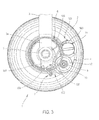
- the engine block 4, 104 comprises a motor 11 (more specifically, an electric motor which here is a brushless synchronous motor) and a reduction system 12, 112 which connects the motor. output shaft 13 of the motor 11 to the drive member 6.
- the reduction system 12, 112 is integral with the motor 11.
- the electric motor 11, thus arranged, can be easily cooled by the ambient air (this cooling depending on the speed of movement of the aircraft).
- the reduction system 12 of the first embodiment comprises a stage which here is formed by an epicyclic gear train.
- the motorization system comprises a second reduction stage formed by the output gear 10 of the engine block 4 (more precisely, the output gear 10 of the reduction system 12) and the ring gear 6 carried by the wheel 2.
- the reduction system 12 of the first embodiment is formed by the engagement of a sun gear 13a carried by the output shaft 13 of the engine 11 and satellites 14a carried by a planet carrier 14.
- the reduction ratio is preferably greater than 5 (here it is 7.5).
- the second stage (outside the engine block) is formed by the meshing of the output gear 10 of the engine block 4 carried by the satellite gate 14 and the ring gear 6 carried by the wheel 2 (the reduction ratio is here 6 8).
- the total reduction ratio is 51.
- the reduction system 12 is aligned with the motor 11, so that the output shaft 13 of the motor 11 is coaxial with the output shaft 8 of the reduction system 12 (which is also the output shaft 8 of the engine block 4).
- the two motor blocks 4, 104 are integral with each other.
- the two engine blocks 4, 104 are arranged between the two wheels 2.
- the two engine blocks 4, 104 are arranged behind the suspension leg 3.
- the two engine blocks 4, 104 are arranged contiguous to one another.
- the output shafts 10 of the engine blocks 4 are parallel.
- the ring gear 6 carries two cylindrical rolling lips 15 which are adapted to receive in rolling bearing without sliding two raceways 16 carried by the output gear 10 of the engine block 4, 104.
- the rolling diameters of the tread 15 and Runways 16 correspond to the pitch diameters of the gears 6, 10.
- the pinion 10 is carried by the output shaft 8 of the engine block 4 via a constant velocity joint 250, Figure 6C , which accepts angular deformation while transmitting the drive torque without speed variation.
- This homokinetic joint may be, for example, a sliding tripod joint or a ball-and-socket joint to further permit axial displacement. This use of a constant velocity joint is not usual.
- the conventional use of a constant velocity joint is the same as that of a universal joint, that is to say that it works in pure torsion, the radial and axial forces being taken up by the bearings supporting the axes.
- the constant velocity joint is used to transmit a radial force (thrust force of the clutch device) and a tangential force (driving force). The seal then makes it possible to absorb a misalignment between the reducer and the wheel.
- the use of the rolling tracks which define the meshing distance and the position of the constant velocity joint complement the device and allow to achieve a gear transmission working under strong deformation of the wheel relative to the gearbox, for example a angular deformation of several degrees (for example of the order of +/- 5 °).
- the clutch device 7 of a motorization system is shaped so as to be able to move the motor unit 4, 104 between an engaged position in which the block 4, 104 is connected to the drive member 6 ( output gear 10 of the reduction system 12, 112 meshing with the ring gear 6 of the wheel 2, as illustrated in FIGS. figures 2 and 9 ), and a disengaged position in which the block 4, 104 is separated from the drive member 6 (pinion 10 disengaged from the ring gear 6, as shown in FIG. figure 3 ).
- the set of two drive systems comprises only one clutch device 7.
- the clutch device 7 is shaped so that the engine block 4, 104 is rotatably mounted (relative to the axle beam 5) along a horizontal axis. More specifically, the engine block 4, 104 is pivotally connected to the unsprung portion 3a of the strut 3 by a pivot 150 (the pivoting connection of the engine block 4, 104 is formed on a fastener 151 carried by axle beam 5).
- the clutch corresponds to a movement of the engine block 4, 104 forwards and upwards, and the clutch has a movement backwards and downwards.
- the clutch device 7 is associated with an electronically controlled speed adaptation system. This system comprises a sensor for measuring the speed of the wheel 2 and controlling the corresponding rotational speed of the motor 11.
- the clutch device 7 comprises a displacement system 152 for moving the engine block 4, 104 from one to the other of its two positions engaged and disengaged, and a guided rod 153 to define the position disengaged from the engine block 4, 104.
- the displacement system 152 comprises a jack 154 connected to the engine block 4, 104 and to the unsprung portion 3a of the strut 3. More specifically, one end of the jack 154 (here, the cylinder 155) is mounted in rotation along a horizontal axis on the fastener 151. The other end is rotatably mounted with two connecting rods 156, 157 along two horizontal axes, one of these rods 156 is also mounted in rotation along a horizontal axis on the piece of 151, the other rod 157 is rotated along a horizontal axis on the engine block 4, 104.
- the cylinder 154 is an electric cylinder. More specifically, this jack 154 comprises a drive motor which is disposed in the cylinder 155, a nut 158 which are connected to the two connecting rods 156, 157, and a screw (for example ball or satellite rollers).
- the clutch device 7 (more specifically, the displacement system 152 with the toggle joint 156, 157 associated therewith) makes it possible to apply a sufficient force to the output gear 10, 110 of the engine block 4, 104 so as to keep in gear with the ring gear 6. Due to the relative position of the engine blocks 4, 104, they are naturally driven, by their weight, in the disengaged position. As a result, when the cylinder 154 no longer exerts any force (as soon as the power supply of the drive motor is cut off), the motor blocks 4, 104 move into their disengaged position.
- the guided rod 153 as for it makes it possible to define the disengaged position of the engine block 4, 104.
- the guided rod 153 comprises a rod 159 which is rotatably mounted (at one end) on the fastener 151 about a fixed horizontal axis.
- the rod 159 is slidably mounted through a pivot 160 which is carried by the engine blocks 4, 104.
- a damping unit 161 At the free end of the rod 159 is disposed a damping unit 161 allowing to absorb shocks on landing.
- this damping unit 161 is formed by a fixed stop 162 (in this case, two nuts 162a, 162b) attached to the free end of the rod 159, a movable stop 163 (in this case a washer 163).
- the pivot 160 rotatably mounted relative to the engine block 4, 104, causes the rotation and sliding of the rod 159.
- the movable stop 163 is in abutment against a shoulder of the end of the rod 159 (the movable stop 163 can not slide over the entire length of the rod 159) so as to ensure prestressing of the organ elastic 164.
- the movable stop 163 is pressed against the pivot 160 and therefore compresses the elastic member 164.
- the elastic member thus makes it possible to absorb 'landing.
- the displacement system 152 may also comprise a return spring (not shown) urging the engine blocks 4, 104 in their disengaged position, against the effect of which the cylinder 154 acts as it drives the engine blocks 4, 104 in the engaged position.
- the displacement system 152 is adapted to apply to the engine block 4, 104 (to the pinion 10) a force greater than a limit value necessary for the engine block 4, 104 remains in the engaged position (so that the pinion 10 and the ring gear remain in mesh).
- This force may be constant or, on the contrary, regulated to a value adapted to the force required to transmit the engine or braking torque.
- the figure 10 represents a main landing gear 1 of an aircraft, one of the two wheels 2 of this train being shown without tire or rim for the sake of clarity.
- the train 1 also comprises a set of two wheel drive systems, namely, a wheel system.
- a motorization system comprises a block motor / gearbox 4, 104 which is carried by the unsprung portion 3a of the strut 3. Similar to the first embodiment, it also comprises a drive member 6 which is integral with the wheel 2, and a clutch device 7 (not visible on the figure 10 ) which allows to connect to the drive member 6 a pinion 10 integral with the output shaft 8 of the engine block 4.
- the motor unit 4 comprises a motor 11 and a reduction system 12, 112 which makes it possible to connect the output shaft 13 of the motor 11 to the drive member 6.
- the reduction system 12, 112 is secured to the motor 11.
- the engine assembly thus disposed can be easily cooled by the ambient air flowing around the wheels of the aircraft.
- the reduction system 12, 112 comprises two stages arranged in cascade.
- each floor is formed by a single train.
- the motorization system comprises a third reduction stage formed by the output gear of the engine block (more precisely, the output gear 10 of the reduction system 12) and the ring gear 6 carried by the wheel 2.
- the first stage of the reduction system 12 is formed by the engagement of a first drive pinion 201 carried by the output shaft of the motor 11 and a first gear wheel 203 (the reduction ratio is here about 3).
- the second stage is formed by the meshing of a second gear 205 carried by the first gear 203 and a second gear 207 (the reduction ratio here is about 2.5).
- the third stage (out of the engine block) is formed by the meshing of the output gear 10 of the engine block 4 carried by the output shaft 8 secured to the second gear 207, and the ring gear 6 carried by the wheel 2 (the reduction ratio is here about 7).
- the two motor blocks 4, 104 are integral with each other (here they are protected from the outside by the same housing). For reasons of compactness, the two engine blocks 4, 104 are arranged between the two wheels 2. In addition, to reduce the risk of collision with external objects (or birds), especially during the take-off and landing phases the two engine blocks 3 are preferably arranged behind the suspension strut 3.
- the two motor blocks are arranged in a V relation to each other so that the output shafts 8, and therefore the pinions 10, are on the same axis, in a manner similar to the figure 8 .
- This allows a symmetrical operation allowing a better effectiveness of the meshing.
- this V arrangement allows the engine blocks 4, 104 not to touch the ground on landing if a tire bursts and protect the second engine impacts (birds, etc.).
- the low tip of the V corresponds to the common axis of the two output shafts 8 of the two reduction systems 12, 112, each upper end of the V corresponding to the axis of a motor 11.
- this V-shaped arrangement of gearboxes is advantageous for the lubrication of the gears. During operation, the gears circulate the oil (which is at rest in the tank located in the tip of the V) to the first stage which allows lubrication of all the gears.
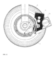
- the sprocket-gear meshing is substantially at the same height as the wheel axis in this embodiment of the invention, Figure 11 , which makes it possible to better accommodate the deformations of the crossmember or the wheel.
- the expression "substantially at the same height” must be interpreted in this context as a positioning of the meshing precisely at the same height or in an angular sector ranging from 20 ° below the horizontal to 20 ° above the horizontal .
- the clutch device 7 of a motorization system is shaped, Figures 11 and 12 , so as to be able to move the engine block 4 between an engaged position in which this block 4 is connected to the drive member 6 (output gear 10 meshing with the ring gear 6 of the wheel 2, as illustrated in FIG. the figure 11 ), and a disengaged position in which this block 4 is separated (pinion 10 disengaged from the ring gear 6, as shown in FIG. figure 12 ).
- the set of two drive systems comprises only four
- the speed synchronization between the pinion gear 10 and the ring gear 6 is carried out separately for each pair of wheels 2 / engine block 4.
- the clutch device 7 is shaped so that the engine block 4 is mounted to rotate (relative to the unsprung portion of the strut 3) along a horizontal axis 226.
- the clutch corresponds to a movement of the engine block 4 upwards and forwards, and the clutch has a downward and a backward movement.
- the gear unit is mounted on the clutch via a rotary shaft 220 substantially vertical.
- the clutch device 7 comprises two fixed planes 222, 224 attached to the unsprung portion 3A of the strut and forming two planes parallel to the wheels. These two planes carry at one of their end the vertical axis 220 on which is fixed a horizontal shaft 226. On this horizontal shaft is fixed pivoting the engine block 4. The engine block is also fixed at one end of a connecting rod 228 defining the first leg of a toggle joint. Thus the engine block pivots around the horizontal shaft 226 under the action of the connecting rod 228.
- This connecting rod 228 is shaped like a V whose tip corresponds to the end on which is fixed the engine block by means of a ball joint. At its other ends are fixed two other rods 230, 232 whose opposite ends are fixed, mounted in rotation along a horizontal axis, on one of the vertices of the fixed planes 222, 224.
- the movements of the joints between the connecting rods 228 and 230 , 232 are rotatable about a horizontal axis and limited in a vertical displacement by the sliding of the axis of rotation 233 in a slot 234 in a vertical plate supporting the displacement system 236, this axis 233 corresponding to the pivot axis of the knee pad.
- the displacement system 236 comprises a jack 238 connected to the pivot axis 233 of the toggle joint and to the unsprung portion of the strut 3 via the plates 222, 224 via the pivot point 240.
- the clutch device 7 (more precisely, the displacement system 236) makes it possible to apply a sufficient force to the output gear 10 of the engine block 4 in order to keep it meshing with the ring gear 6.
- the displacement system 236 comprises a return spring 242 which, here, envelops the cylinder 238.
- the cylinder 238 is used to drive the engine block 4 in its engaged position and the spring 242 is used to drive it into its unengaged position.
- the spring 242 also ensures that there is no meshing of the pinion 10 on the toothed wheel 6 during landing.
- the displacement system 236 is adapted to apply to the engine block 4 (to the pinion 10) a force greater than a limit value necessary for the engine block 4 remains in the engaged position (so that the pinion 10 and the ring gear remain intermeshed).
- This force may be constant or, on the contrary, regulated to a value adapted to the force required to transmit the engine or braking torque.
- the clutch is forced by a mechanical effect of the force of the teeth on the engine block when a bearing limit force is reached. It can also be controlled following an alert from another element of the system such as reaching a given engine torque level.
- the fact that the two output gears 10 of the engine blocks 104 are coaxial makes it possible to mount the system on a more flexible articulation, or else to put flexibility in the system itself, this makes it possible to recover the deformations encountered, for example those of the wheels 2, the forces generated on the two toothed rings 6 of the two wheels 2 being comparable.
- the forces can however differ substantially if the ground adhesion coefficients encountered by each wheel of the train are different.
- this engine system is used for example during the phases before take-off, after landing, that is to say for any ground travel as long as the speed is less than the speed maximum taxiing allowed. During these phases, it is therefore possible to not use the main engines of the aircraft, which reduces fuel consumption, and therefore the costs and emissions of pollutants and CO 2 . Another consequence of the extinction of the main engines of the aircraft is a decrease in noise.
- This drive system is electronically controlled so that the engine block is in the disengaged position during the landing and takeoff phases and during the flight.
- the present invention is not limited to the present embodiment.
- the leg could carry a different number of wheels, depending on the size of the aircraft (from a wheel to eight). There could also be several systems per wheel (a wheel driven by multiple engines). It is also possible that some wheels (or only one) is motorized.
Abstract
Description
La présente invention concerne un système de motorisation d'une roue d'un aéronef, par exemple appliqué à un avion, pour la circulation de celui-ci au sol.The present invention relates to a motorization system of a wheel of an aircraft, for example applied to an aircraft, for the circulation of the latter on the ground.
Lorsque l'on parle de motoriser la circulation des aéronef au sol, il s'agit de motoriser le déplacement des aéronefs de manière autonome mais à des vitesses réduites comme c'est le cas pour un avion avant son décollage ou après son atterrissage sur les aéroports, il s'agit de ce qu'on appelle couramment le « taxiing » Il ne s'agit donc pas ici de motoriser la roue de manière à lui donner vitesse en rapport avec la vitesse d'atterrissage comme on l'a déjà proposé dans l'état de la technique.When it comes to motorizing the movement of aircraft on the ground, it is a matter of motorizing the movement of aircraft autonomously but at reduced speeds as is the case for an aircraft before takeoff or after landing on aircraft. airports, this is what is commonly called "taxiing" It is not a question here of motorizing the wheel so as to give it speed in relation to the landing speed as it has already been proposed in the state of the art.
On connaît un système de motorisation d'une roue associée à une suspension, du type comprenant un bloc moteur, un organe d'entraînement solidaire de la roue, et un dispositif d'embrayage reliant l'arbre de sortie du bloc moteur à l'organe d'entraînement.There is known a motorization system of a wheel associated with a suspension, of the type comprising an engine block, a drive member integral with the wheel, and a clutch device connecting the output shaft of the engine block to the driving member.
Cependant, de tels systèmes sont souvent peu compatibles avec les déformations de la suspension et de la jante de la roue, déformations qui interviennent lors des différentes manoeuvres au sol tel que les virages ou les freinages.However, such systems are often not very compatible with the deformations of the suspension and rim of the wheel, deformations that occur during the various ground maneuvers such as bends or braking.
La présente invention vise à réaliser un système de motorisation pouvant supporter facilement les déformations de la jambe de suspension et de la roue elle-même.The present invention aims to achieve a motorization system that can easily withstand the deformation of the strut and the wheel itself.
Selon l'invention, dans le système de motorisation du type précité, le bloc moteur comprend un moteur électrique et est porté par une partie non suspendue d'une jambe de suspension.According to the invention, in the motorization system of the aforementioned type, the engine block comprises an electric motor and is carried by an unsprung portion of a suspension strut.
Ainsi, l'intégralité du système de motorisation est portée par la partie non suspendue de la jambe de suspension : d'une part, l'organe d'entraînement par la roue, et, d'autre part, le bloc moteur et le dispositif d'embrayage par la traverse d'essieu, ce qui facilite l'intégration du système de motorisation. De plus, du fait de cette disposition, il n'est pas nécessaire de tenir compte du mouvement de l'amortisseur de la suspension pour la mise en relation de l'arbre de sortie du bloc moteur à l'organe d'entraînement.Thus, the entire motorization system is carried by the unsprung portion of the strut: on the one hand, the drive member by the wheel, and, on the other hand, the engine block and the device clutch through the axle beam, which facilitates the integration of the drive system. In addition, because of this arrangement, it is not necessary to take into account the movement of the shock absorber of the suspension for the connection of the output shaft of the engine block to the drive member.
Selon une première variante, le bloc moteur est porté par une traverse d'essieu de la roue.According to a first variant, the engine block is carried by an axle cross member of the wheel.
Selon une seconde variante, le bloc moteur comprend un système de réduction reliant l'arbre de sortie du moteur à l'organe d'entraînement.According to a second variant, the engine block comprises a reduction system connecting the output shaft of the motor to the drive member.
Selon une troisième variante, le système de réduction est solidaire du moteur.According to a third variant, the reduction system is integral with the engine.
Selon une quatrième variante, le dispositif d'embrayage est conformé de façon à pouvoir déplacer le bloc moteur dans une position embrayée dans laquelle ce bloc est relié à l'organe d'entraînement, et une position débrayée dans laquelle ce bloc en est séparé.According to a fourth variant, the clutch device is shaped so as to move the engine block in an engaged position in which the block is connected to the drive member, and a disengaged position in which the block is separated.
Selon une cinquième variante, le dispositif d'embrayage est conformé de sorte que le bloc moteur est monté pivotant par rapport à la traverse d'essieu, selon un axe horizontal.According to a fifth variant, the clutch device is shaped so that the engine block is pivotally mounted relative to the cross axle, along a horizontal axis.
Selon une sixième variante, le dispositif d'embrayage comprend un système de déplacement permettant de déplacer le bloc moteur de l'une à l'autre de ses deux positions embrayée et débrayée.According to a sixth variant, the clutch device comprises a displacement system for moving the engine block from one to the other of its two positions engaged and disengaged.
Selon une septième variante, le système de déplacement est adapté à appliquer au bloc moteur une force supérieure à une valeur limite nécessaire pour que le bloc moteur reste en position embrayée.According to a seventh variant, the displacement system is adapted to apply to the engine block a force greater than a limit value necessary for the engine block remains in the engaged position.
Selon une huitième variante, le système de déplacement comprend un élément moteur.According to an eighth variant, the displacement system comprises a motor element.
Selon une neuvième variante, l'élément moteur est formé par un vérin.According to a ninth variant, the driving element is formed by a jack.
Selon une dixième variante, une extrémité du vérin est montée en rotation sur une pièce de fixation solidaire de la traverse, l'autre extrémité du vérin étant montée en rotation à deux bielles, l'une de ces bielles étant montée en rotation sur la pièce de fixation, l'autre bielle étant montée en rotation sur le bloc moteur.According to a tenth variant, one end of the jack is rotatably mounted on a fastener integral with the cross member, the other end of the jack being rotatably mounted with two connecting rods, one of these rods being rotatably mounted on the piece. fixing, the other connecting rod being rotatably mounted on the engine block.
Selon une onzième variante, le bloc moteur est agencé de façon à être naturellement entraîné par son propre poids en position débrayée.According to an eleventh variant, the engine block is arranged to be naturally driven by its own weight in the disengaged position.
Selon une douzième variante, le dispositif d'embrayage comprend une bielle guidée permettant de définir la position débrayée du mouvement du bloc moteur.According to a twelfth variant, the clutch device comprises a guided connecting rod for defining the disengaged position of the movement of the engine block.
Selon une treizième variante, la bielle guidée comprend une tige, ladite tige étant, d'une part, montée en rotation sur une pièce de fixation solidaire de la traverse, et, d'autre part, montée coulissante par rapport à un pivot porté par le bloc moteur.According to a thirteenth variant, the guided rod comprises a rod, said rod being, on the one hand, rotatably mounted on a fastener integral with the cross member, and, on the other hand, slidably mounted relative to a pivot carried by the engine block.
Selon une quatorzième variante, une unité d'amortissement permettant d'absorber les chocs du bloc moteur est disposée entre le pivot et l'extrémité libre de la tige.According to a fourteenth variant, a damping unit for absorbing the shocks of the engine block is disposed between the pivot and the free end of the rod.
Selon une quinzième variante, l'unité d'amortissement est formée par une butée fixe fixée à l'extrémité libre de la tige, une butée mobile montée coulissante le long de la tige entre l'extrémité libre de cette dernière et le pivot, et un organe élastique disposé entre les deux butées de façon à ce que l'organe élastique soit précontraint entre les deux butées lors que le bloc moteur n'est pas en position débrayée.According to a fifteenth variant, the damping unit is formed by a fixed abutment fixed to the free end of the rod, a movable abutment slidably mounted along the rod between the free end of the rod and the pivot, and an elastic member disposed between the two stops so that the elastic member is prestressed between the two stops when the engine block is not in the disengaged position.
Selon une seizième variante, l'organe d'entraînement est une couronne dentée portée par la jante de la roue, et adaptée à recevoir en engrènement le pignon de sortie du bloc moteur quand ce dernier est dans sa position embrayée.According to a sixteenth variant, the drive member is a ring gear carried by the rim of the wheel, and adapted to receive in meshing the output gear of the engine block when the latter is in its engaged position.
Selon une dix-septième variante, la position engrenée du pignon de sortie est définie par deux lèvres de roulement portées par la couronne dentée et adaptées à recevoir en roulement sans glissement deux pistes de roulement portées par le pignon.According to a seventeenth variant, the geared position of the output gear is defined by two bearing lips carried by the ring gear and adapted to receive rolling without sliding two tracks carried by the pinion.
L'invention concerne également un ensemble de deux systèmes de motorisation conformes au premier aspect de l'invention, les deux blocs moteur étant solidaires l'un de l'autre et fixés à la partie non suspendue de la jambe de suspension commune aux deux roues.The invention also relates to a set of two motorization systems according to the first aspect of the invention, the two engine blocks being integral with each other and fixed to the unsprung portion of the suspension strut common to both wheels. .
Selon une première variante, les deux blocs moteur sont disposés entre les deux roues.According to a first variant, the two engine blocks are arranged between the two wheels.
Selon une deuxième variante, les deux blocs moteur sont disposés derrière une jambe de suspension portant la traverse d'essieu.According to a second variant, the two engine blocks are arranged behind a suspension strut carrying the cross axle.
Selon une troisième variante, l'ensemble de deux systèmes de motorisation ne comprend qu'un seul dispositif d'embrayage commun aux deux systèmes.According to a third variant, the set of two drive systems comprises only one clutch device common to both systems.
Un tel système de motorisation ou un tel ensemble de deux systèmes de motorisation, selon le cas, est avantageusement utilisé pour la motorisation d'un train d'atterrissage principal d'un aéronef.Such a motorization system or such a set of two motorization systems, as appropriate, is advantageously used for the motorization of a main landing gear of an aircraft.
D'autres particularités et avantages de la présente invention apparaîtront dans les deux modes de réalisation donnés à titre d'exemples non limitatifs et illustrés par les dessins mis en annexe dans lesquels :
- La
figure 1 est une vue en perspective arrière d'un train d'atterrissage d'avion équipé d'un ensemble de deux systèmes de motorisation de roue conformes à un premier mode de réalisation de la présente invention, l'ensemble étant embrayé aux roues ; - La
figure 2 est une vue en coupe selon un plan perpendiculaire à l'axe des roues du train d'atterrissage de lafigure 1 , l'ensemble des deux systèmes étant en position embrayée ; - La
figure 3 est une vus similaire à lafigure 2 , l'ensemble des deux systèmes de motorisation étant en position débrayée ; - La
figure 4 est une vue en coupe du système de déplacement du dispositif d'embrayage de l'ensemble des deux systèmes de motorisation ; - La
figure 5 est une vue de la bielle guidée du dispositif d'embrayage de l'ensemble des deux systèmes de motorisation ; - La
figure 6A est une vue illustrant la coopération entre une roue et l'arbre de sortie du bloc moteur correspondant; - La
figure 6B est une vue en perspective du mécanisme de lafigure 6A ; - La
figure 6C est une vue en perspective similaire à lafigure 6B mais dans laquelle le pignon a été oté pour faire apparaître le joint homocinétique interne ; - La
figure 7 est une vue en coupe axiale d'un bloc moteur, sans le pignon de sortie de ce dernier ; - La
figure 8 est une vue similaire à lafigure 1 , illustrant un second mode de réalisation de la présente invention ; - La
figure 9 est une vue similaire à lafigure 2 de l'ensemble des deux systèmes de motorisation conforme au second mode de réalisation ; - La
figure 10 est une vue en perspective d'un train d'atterrissage d'avion équipé d'un ensemble de deux systèmes de motorisation de roue conformes à un second mode de réalisation de la présente invention, l'ensemble étant embrayé aux roues et la roue la plus proche étant représentée sans pneu ni jante ; - La
figure 11 est une vue en coupe selon un plan perpendiculaire à l'axe des roues du train d'atterrissage de lafigure 10 , l'ensemble des deux systèmes étant en position embrayée ; - La
figure 12 est une vue similaire à lafigure 11 , l'ensemble des deux systèmes étant en position débrayée ; - La
figure 13 est une vue en perspective du dispositif d'embrayage de l'ensemble des deux systèmes ; - La
figure 14 est une vue en coupe dans un plan comprenant les axes des engrenages du bloc réducteur de ce second mode de réalisation ; et
- The
figure 1 is a rear perspective view of an aircraft landing gear equipped with a set of two wheel drive systems according to a first embodiment of the present invention, the assembly being engaged with the wheels; - The
figure 2 is a sectional view along a plane perpendicular to the axis of the wheels of the landing gear of thefigure 1 , all of the two systems being in the engaged position; - The
figure 3 is a similar view to thefigure 2 , all of the two actuator systems being in the disengaged position; - The
figure 4 is a sectional view of the displacement system of the clutch device of all two drive systems; - The
figure 5 is a view of the guided connecting rod of the clutch device of all two drive systems; - The
Figure 6A is a view illustrating the cooperation between a wheel and the output shaft of the corresponding engine block; - The
Figure 6B is a perspective view of the mechanism of theFigure 6A ; - The
Figure 6C is a perspective view similar to theFigure 6B but in which the pinion was removed to reveal the internal constant velocity joint; - The
figure 7 is an axial sectional view of an engine block, without the output gear of the latter; - The
figure 8 is a view similar to thefigure 1 illustrating a second embodiment of the present invention; - The
figure 9 is a view similar to thefigure 2 of all the two motorization systems according to the second embodiment; - The
figure 10 is a perspective view of an aircraft landing gear equipped with a set of two wheel drive systems according to a second embodiment of the present invention, the assembly being engaged with the wheels and the wheel closer being shown without tire or rim; - The
figure 11 is a sectional view along a plane perpendicular to the axis of the wheels of the landing gear of thefigure 10 , all of the two systems being in the engaged position; - The
figure 12 is a view similar to thefigure 11 , all of the two systems being in the disengaged position; - The
figure 13 is a perspective view of the clutch device of all two systems; - The
figure 14 is a sectional view in a plane comprising the gear shafts of the reducing unit of this second embodiment; and
Les
Un système de motorisation conforme à la présente invention comprend un bloc moteur 4, 104 qui est solidaire de la traverse d'essieu 5 de la roue 2, un organe d'entraînement 6 qui est solidaire de la roue 2, et un dispositif d'embrayage 7 qui permet de relier l'arbre de sortie 8 du bloc moteur 4, 104 à l'organe d'entraînement 6. De façon plus précise, le bloc moteur 4, 104 et le dispositif d'embrayage 7 sont disposés à l'extérieur de la traverse 5 et sont reliés l'un à l'autre tout en étant en porte à faux par rapport à cette traverse.A motorization system according to the present invention comprises a
Ainsi, l'ensemble du système de motorisation est porté par la partie non suspendue 3a de la jambe de suspension 3 : le bloc moteur 4, 104 et le dispositif d'embrayage 7 sont portés par la traverse d'essieu 5, et l'organe d'entraînement 6 est porté par la roue 2.Thus, the entire motorization system is carried by the unsprung portion 3a of the strut 3: the
Dans les présents modes de réalisation, l'organe d'entraînement 6 solidaire de la roue 2 est formé par une couronne dentée 6 portée par la jante 9 de cette roue 2, cette couronne 6 recevant en engrènement le pignon de sortie 10 du bloc moteur 4, 104 quand ce dernier est dans sa position embrayée. Ce type de transmission par pignons et roues dentées est qualifié de transmission « positive » par opposition aux systèmes de transmission par frottement comme les systèmes à galets. Une transmission positive n'est pas tributaire du coefficient de frottement et donc par exemple insensible aux intempéries ou à l'usure des éléments mis en oeuvre. On classe donc également les systèmes à courroies crantées parmi les transmissions positives, alors que les courroies lisses (plates ou en V) sont classées parmi les systèmes de transmission par frottement.In the present embodiments, the drive member 6 secured to the
Par ailleurs, dans les présents modes de réalisation, le bloc moteur 4, 104 comprend un moteur 11 (plus précisément, un moteur électrique qui, ici, est un moteur synchrone sans balai) et un système de réduction 12, 112 qui relie l'arbre de sortie 13 du moteur 11 à l'organe d'entraînement 6. Ici, le système de réduction 12, 112 est solidaire du moteur 11. Le moteur électrique 11, ainsi disposé, peut être facilement refroidi par l'air ambiant (ce refroidissement dépendant de la vitesse de déplacement de l'aéronef).Furthermore, in the present embodiments, the
Comme illustré à la
De façon plus précise, le système de réduction 12 du premier mode de réalisation est formé par l'engrènement d'un pignon solaire 13a porté par l'arbre de sortie 13 du moteur 11 et de satellites 14a portés par un porte-satellites 14. Le rapport de réduction est de préférence supérieur à 5 (ici, il est de 7,5). Le second étage (hors du bloc moteur) est formé par l'engrènement du pignon de sortie 10 du bloc moteur 4 porté par le porte satellite 14 et par la couronne dentée 6 portée par la roue 2 (le rapport de réduction est ici de 6,8). Ainsi, dans le présent cas, le rapport de réduction total est de 51. Ici, le système de réduction 12 est aligné avec le moteur 11, de sorte que l'arbre de sortie 13 du moteur 11 est coaxial avec l'arbre de sortie 8 du système de réduction 12 (qui est aussi l'arbre de sortie 8 du bloc moteur 4).More specifically, the
Dans l'ensemble de deux systèmes de motorisation illustrés aux
Dans le premier mode de réalisation, les arbres de sortie 10 des blocs moteurs 4 sont parallèles.In the first embodiment, the
Afin de définir la position d'engrènement du bloc moteur 4, 104 (plus, précisément, celle du pignon 10),
Enfin, afin de compenser une variation angulaire entre l'arbre de sortie 8 du bloc moteur 4 et la couronne dentée 6 de la roue 2 qui serait engendrée par la déformation du train d'atterrissage sous charge, le pignon 10 est porté par l'arbre de sortie 8 du bloc moteur 4 par l'intermédiaire d'un joint homocinétique 250,
De plus, l'utilisation des pistes de roulement qui définissent l'entraxe d'engrènement et la position du joint homocinétique complètent le dispositif et permettent de réaliser une transmission par engrenage travaillant sous forte déformation de la roue par rapport au réducteur, par exemple une déformation angulaire de plusieurs degrés (par exemple de l'ordre de +/- 5°).In addition, the use of the rolling tracks which define the meshing distance and the position of the constant velocity joint complement the device and allow to achieve a gear transmission working under strong deformation of the wheel relative to the gearbox, for example a angular deformation of several degrees (for example of the order of +/- 5 °).
Par ailleurs, le dispositif d'embrayage 7 d'un système de motorisation est conformé de façon à pouvoir déplacer le bloc moteur 4, 104 entre une position embrayée dans laquelle le bloc 4, 104 est relié à l'organe d'entraînement 6 (pignon de sortie 10 du système de réduction 12, 112 engrené à la couronne dentée 6 de la roue 2, tel qu'illustré aux
Dans les présents modes de réalisation, le dispositif d'embrayage 7 est conformé de sorte que le bloc moteur 4, 104 est monté en rotation (par rapport à la traverse d'essieu 5) selon un axe horizontal. De façon plus précise, le bloc moteur 4, 104 est relié de façon pivotante à la partie non suspendue 3a de la jambe de suspension 3 par un pivot 150 (la liaison pivotante du bloc moteur 4, 104 est réalisée sur une pièce de fixation 151 portée par la traverse d'essieu 5). Ainsi, l'embrayage correspond à un mouvement du bloc moteur 4, 104 vers l'avant et vers le haut, et le débrayage à un mouvement vers l'arrière et vers le bas.In the present embodiments, the
Au dispositif d'embrayage 7 est associé un système d'adaptation de vitesse commandé électroniquement. Ce système comprend un capteur permettant de mesurer la vitesse de la roue 2 et de commander la vitesse de rotation correspondante du moteur 11.The
Dans les présents modes de réalisation, comme illustré aux
Comme illustré à la
Le dispositif d'embrayage 7 (plus précisément, le système de déplacement 152 avec la genouillère 156, 157 qui y est associée) permet d'appliquer une force suffisante sur le pignon de sortie 10, 110 du bloc moteur 4, 104 afin de le maintenir engrené avec la couronne dentée 6. Du fait de la position relative des blocs moteur 4, 104, ceux-ci sont naturellement entraînés, par leur poids, en position débrayée. De ce fait, quand le vérin 154 n'exerce plus aucun effort (dès que l'alimentation électrique du moteur d'entraînement est coupée), les blocs moteurs 4, 104 passent dans leur position débrayée.The clutch device 7 (more specifically, the
La bielle guidée 153 quant à elle permet de définir la position débrayée du bloc moteur 4, 104. Comme illustré à la
De ce fait, quand le bloc moteur 4, 104 est en position débrayée, la butée mobile 163 est appuyée contre le pivot 160 et de ce fait comprime l'organe élastique 164. L'organe élastique permet ainsi d'absorber le choc à l'atterrissage.Therefore, when the
Afin d'éviter un embrayage lors des opérations de freinage, d'atterrissage, de décollage ou de toute autre opération qui donnerait lieu à des accélérations qui auraient tendance à ramener le bloc moteur en position embrayée, le système de déplacement 152 peut également comprendre un ressort de rappel (non illustré) sollicitant les blocs moteurs 4, 104 dans leur position débrayée, contre l'effet duquel le vérin 154 agit lorsqu'il entraîne les blocs moteur 4, 104 en position embrayée.In order to avoid a clutch during braking, landing, take-off or any other operation which would give rise to accelerations which would tend to bring the engine block into the engaged position, the
Le système de déplacement 152 est adapté à appliquer au bloc moteur 4, 104 (au pignon 10) une force supérieure à une valeur limite nécessaire pour que le bloc moteur 4, 104 reste en position embrayée (pour que le pignon 10 et la couronne dentée restent engrenés). Cette force peut être constante ou au contraire régulée à une valeur adaptée à l'effort nécessaire permettant de transmettre le couple moteur ou freineur.The
Vu la configuration géométrique du système de motorisation, les efforts d'engrènement incitent au désengrènement lors d'une marche avant de l'avion et à l'engrènement lors d'une marche arrière. De ce fait, en marche avant, le vérin 154 doit être suffisamment puissant pour maintenir l'embrayage. Un changement de position du pivot 150 reliant les blocs moteur 4, 104 à la pièce de fixation 151 vers l'arrière permettrait d'avoir un système auto dégageant en marche arrière comme en marche avant.Given the geometrical configuration of the motorization system, the meshing forces encourage disengagement during a forward movement of the aircraft and meshing during a reverse. Therefore, in the forward direction, the
Maintenant va être décrit un second mode de réalisation du système de motorisation. Dans les figures, les parties identiques ou similaires entre les deux modes de réalisation portent les mêmes références d'un mode de réalisation à l'autre.Now will be described a second embodiment of the motorization system. In the figures, the same or similar parts between the two embodiments bear the same references from one embodiment to another.
La
Un système de motorisation conforme à un second mode de réalisation de l'invention comprend un bloc moteur/réducteur 4, 104 qui est porté par la partie non suspendue 3a de la jambe de suspension 3. De façon similaire au premier mode de réalisation, il comprend également un organe d'entraînement 6 qui est solidaire de la roue 2, et un dispositif d'embrayage 7 (non visible sur la
Comme précédemment, le bloc moteur 4 comprend un moteur 11 et un système de réduction 12, 112 qui permet de relier l'arbre de sortie 13 du moteur 11 à l'organe d'entraînement 6. Ici, le système de réduction 12, 112 est solidaire du moteur 11. L'ensemble de motorisation ainsi disposé peut être facilement refroidi par l'air ambiant circulant autour des roues de l'aéronef.As before, the
Comme illustré à la
De façon plus précise, le premier étage du système de réduction 12 est formé par l'engrènement d'un premier pignon moteur 201 porté par l'arbre de sortie du moteur 11 et d'une première roue dentée 203 (le rapport de réduction est ici d'environ 3). Le second étage est formé par l'engrènement d'un second pignon 205 porté par la première roue dentée 203 et d'une seconde roue dentée 207 (le rapport de réduction est ici d'environ 2,5). Le troisième étage (hors du bloc moteur) est formé par l'engrènement du pignon de sortie 10 du bloc moteur 4 porté par l'arbre de sortie 8 solidaire de la seconde roue dentée 207, et par la couronne dentée 6 portée par la roue 2 (le rapport de réduction est ici d'environ 7).More specifically, the first stage of the
Dans l'ensemble de deux systèmes de motorisation illustré à la
De plus, les deux blocs moteurs sont disposés en V l'un par rapport à l'autre de sorte que les arbres de sortie 8, et donc les pignons 10, sont sur un même axe, de manière similaire à la
De plus, cette disposition en V permet aux blocs moteurs 4, 104 de ne pas toucher le sol à l'atterrissage si un pneu éclate et de protéger le deuxième moteur des impacts (oiseaux, etc.). La pointe basse du V correspond à l'axe commun des deux arbres de sortie 8 des deux systèmes de réduction 12 , 112, chaque extrémité supérieure du V correspondant à l'axe d'un moteur 11. De plus, cette disposition en V des réducteurs est avantageuse pour la lubrification des engrenages. Pendant le fonctionnement, les engrenages font circuler l'huile (qui à repos se trouve dans le réservoir situé dans la pointe du V) jusqu'au premier étage ce qui permet une lubrification de tous les engrenages.In addition, this V arrangement allows the
Il est à noter également que l'engrènement pignon - roue dentée se trouve sensiblement à la même hauteur que l'axe des roues dans ce mode de réalisation de l'invention,
Par ailleurs, le dispositif d'embrayage 7 d'un système de motorisation est conformé,
Le dispositif d'embrayage 7 est conformé de sorte que le bloc moteur 4 est monté en rotation (par rapport à la partie non suspendue de la jambe de suspension 3) selon un axe horizontal 226. Ainsi, l'embrayage correspond à un mouvement du bloc moteur 4 vers le haut et vers l'avant, et le débrayage à un mouvement vers le bas et vers l'arrière.The
De plus, dans
Dans ce mode de réalisation, comme illustré à la
Cette bielle 228 est conformée en V dont la pointe correspond à l'extrémité sur laquelle est fixée le bloc moteur par l'intermédiaire d'une rotule. A ses autres extrémités sont fixés deux autres bielles 230, 232 dont les extrémités opposées sont fixées, montées en rotation selon un axe horizontal, sur l'un des sommets des plans fixes 222, 224. Les mouvements des articulations entre les bielles 228 et 230, 232 sont rotatifs selon un axe horizontal et limités dans un déplacement vertical par le glissement de l'axe de rotation 233 dans une lumière 234 dans une plaque verticale supportant le système de déplacement 236, cet axe 233 correspondant à l'axe pivot de la genouillère.This connecting rod 228 is shaped like a V whose tip corresponds to the end on which is fixed the engine block by means of a ball joint. At its other ends are fixed two other rods 230, 232 whose opposite ends are fixed, mounted in rotation along a horizontal axis, on one of the vertices of the fixed planes 222, 224. The movements of the joints between the connecting rods 228 and 230 , 232 are rotatable about a horizontal axis and limited in a vertical displacement by the sliding of the axis of rotation 233 in a slot 234 in a vertical plate supporting the displacement system 236, this axis 233 corresponding to the pivot axis of the knee pad.
Le système de déplacement 236 comprend un vérin 238 relié à l'axe pivot 233 de la genouillère et à la partie non-suspendue de la jambe de suspension 3 via les plaques 222, 224 par le point d'articulation 240.The displacement system 236 comprises a jack 238 connected to the pivot axis 233 of the toggle joint and to the unsprung portion of the
Le dispositif d'embrayage 7 (plus précisément, le système de déplacement 236) permet d'appliquer une force suffisante sur le pignon de sortie 10 du bloc moteur 4 afin de le maintenir engrené avec la couronne dentée 6.The clutch device 7 (more precisely, the displacement system 236) makes it possible to apply a sufficient force to the
Dans le présent exemple, afin d'avoir un débrayage du bloc moteur 4 dès que l'alimentation électrique du moteur d'entraînement du système de déplacement 236 est coupée, le système de déplacement 236 comprend un ressort de rappel 242 qui, ici, enveloppe le vérin 238. Ainsi, le vérin 238 est utilisé pour entraîner le bloc moteur 4 dans sa position engrenée et le ressort 242 est utilisé pour l'entraîner dans sa position désengrenée. Le ressort 242 assure également qu'il n'y ait pas d'engrènement du pignon 10 sur la roue dentée 6 lors de l'atterrissage.In the present example, in order to have a disengagement of the
Le système de déplacement 236 est adapté à appliquer au bloc moteur 4 (au pignon 10) une force supérieure à une valeur limite nécessaire pour que le bloc moteur 4 reste en position embrayée (pour que le pignon 10 et la couronne dentée restent engrenés). Cette force peut être constante ou au contraire régulée à une valeur adaptée à l'effort nécessaire permettant de transmettre le couple moteur ou freineur.The displacement system 236 is adapted to apply to the engine block 4 (to the pinion 10) a force greater than a limit value necessary for the
Il s'agit aussi d'un système auto-dégageant au cas où une des roues ou un des moteurs se bloque, et ceci quel que ce soit le sens de marche de l'avion, dès que l'effort généré par les dentures est supérieur à celui du système de mise en place. Ainsi, le débrayage est forcé par un effet mécanique de l'effort des dentures sur le bloc moteur quand une force limite d'appui est atteinte. Il peut aussi être commandé suite à une alerte émanant d'un autre élément du système comme par exemple l'atteinte d'un niveau de couple moteur donné.It is also a self-releasing system in the event that one of the wheels or engines crashes, and this whatever the direction of travel of the aircraft, as soon as the force generated by the teeth is higher than that of the placing system. Thus, the clutch is forced by a mechanical effect of the force of the teeth on the engine block when a bearing limit force is reached. It can also be controlled following an alert from another element of the system such as reaching a given engine torque level.
En outre, dans le second mode de réalisation, le fait que les deux pignons de sortie 10 des blocs moteur 104 sont coaxiaux permet de monter le système sur une articulation plus souple, ou alors de mettre de la souplesse dans le système lui-même, ce qui permet de reprendre les déformations rencontrées, par exemple celles des roues 2, les efforts générés sur les deux couronnes dentées 6 des deux roues 2 étant comparables. Les efforts peuvent cependant différer sensiblement si les coefficients d'adhérence au sol rencontrés par chaque roue du train sont différents.In addition, in the second embodiment, the fact that the two output gears 10 of the engine blocks 104 are coaxial makes it possible to mount the system on a more flexible articulation, or else to put flexibility in the system itself, this makes it possible to recover the deformations encountered, for example those of the
Dans la présente application à un avion, ce système de motorisation est utilisé par exemple lors des phases avant le décollage, après l'atterrissage, c'est-à-dire pour tout déplacement au sol pour autant que la vitesse soit inférieure à la vitesse de taxiing maximale autorisée. Pendant ces phases, il est donc possible de ne pas utiliser les moteurs principaux de l'avion, ce qui permet de réduire la consommation de carburant, et donc les coûts et les émissions de polluants et de CO2. Une autre conséquence de l'extinction des moteurs principaux de l'avion est une baisse des nuisances sonores.In the present application to an airplane, this engine system is used for example during the phases before take-off, after landing, that is to say for any ground travel as long as the speed is less than the speed maximum taxiing allowed. During these phases, it is therefore possible to not use the main engines of the aircraft, which reduces fuel consumption, and therefore the costs and emissions of pollutants and CO 2 . Another consequence of the extinction of the main engines of the aircraft is a decrease in noise.
Ce système de motorisation est commandé électroniquement de sorte que le bloc moteur est en position débrayée pendant les phases d'atterrissage et de décollage et pendant le vol.This drive system is electronically controlled so that the engine block is in the disengaged position during the landing and takeoff phases and during the flight.
La présente invention n'est pas limitée au présent mode de réalisation.The present invention is not limited to the present embodiment.
Ainsi, il pourrait être utilisé pour la motorisation d'une roue de nez.Thus, it could be used for the motorization of a nose wheel.
Par ailleurs, la jambe pourrait porter un nombre différent de roues, selon notamment la taille de l'avion (d'une roue à huit). Il pourrait aussi y avoir plusieurs systèmes par roue (une roue entraînée par plusieurs moteurs). Il serait également possible que certaines roues (ou une seule) soit motorisées.In addition, the leg could carry a different number of wheels, depending on the size of the aircraft (from a wheel to eight). There could also be several systems per wheel (a wheel driven by multiple engines). It is also possible that some wheels (or only one) is motorized.
Claims (13)
Applications Claiming Priority (3)
| Application Number | Priority Date | Filing Date | Title |
|---|---|---|---|
| FR0959145A FR2954235B1 (en) | 2009-12-17 | 2009-12-17 | ELECTRIC MOTORIZATION SYSTEM OF A WHEEL |
| PCT/FR2010/052785 WO2011073590A1 (en) | 2009-12-17 | 2010-12-17 | System for electric motorisation of a wheel |
| EP10807612.6A EP2512918B1 (en) | 2009-12-17 | 2010-12-17 | System for electric motorisation of a wheel |
Related Parent Applications (3)
| Application Number | Title | Priority Date | Filing Date |
|---|---|---|---|
| EP10807612.6 Division | 2010-12-17 | ||
| EP10807612.6A Division EP2512918B1 (en) | 2009-12-17 | 2010-12-17 | System for electric motorisation of a wheel |
| EP10807612.6A Division-Into EP2512918B1 (en) | 2009-12-17 | 2010-12-17 | System for electric motorisation of a wheel |
Publications (3)
| Publication Number | Publication Date |
|---|---|
| EP2543591A2 true EP2543591A2 (en) | 2013-01-09 |
| EP2543591A3 EP2543591A3 (en) | 2015-11-11 |
| EP2543591B1 EP2543591B1 (en) | 2020-03-18 |
Family
ID=42563053
Family Applications (5)
| Application Number | Title | Priority Date | Filing Date |
|---|---|---|---|
| EP10807612.6A Active EP2512918B1 (en) | 2009-12-17 | 2010-12-17 | System for electric motorisation of a wheel |
| EP12185386.5A Active EP2543593B1 (en) | 2009-12-17 | 2010-12-17 | System for electric motorisation of a wheel |
| EP12185384.0A Not-in-force EP2543592B1 (en) | 2009-12-17 | 2010-12-17 | System for electric motorisation of a wheel |
| EP12185382.4A Not-in-force EP2543590B1 (en) | 2009-12-17 | 2010-12-17 | System for electric motorisation of a wheel |
| EP12185383.2A Active EP2543591B1 (en) | 2009-12-17 | 2010-12-17 | System for electric motorisation of a wheel |
Family Applications Before (4)
| Application Number | Title | Priority Date | Filing Date |
|---|---|---|---|
| EP10807612.6A Active EP2512918B1 (en) | 2009-12-17 | 2010-12-17 | System for electric motorisation of a wheel |
| EP12185386.5A Active EP2543593B1 (en) | 2009-12-17 | 2010-12-17 | System for electric motorisation of a wheel |
| EP12185384.0A Not-in-force EP2543592B1 (en) | 2009-12-17 | 2010-12-17 | System for electric motorisation of a wheel |
| EP12185382.4A Not-in-force EP2543590B1 (en) | 2009-12-17 | 2010-12-17 | System for electric motorisation of a wheel |
Country Status (7)
| Country | Link |
|---|---|
| US (1) | US8857544B2 (en) |
| EP (5) | EP2512918B1 (en) |
| JP (4) | JP5866519B2 (en) |
| CN (1) | CN102791575B (en) |
| BR (1) | BR112012014324A2 (en) |
| FR (1) | FR2954235B1 (en) |
| WO (1) | WO2011073590A1 (en) |
Families Citing this family (31)
| Publication number | Priority date | Publication date | Assignee | Title |
|---|---|---|---|---|
| GB0915009D0 (en) * | 2009-08-28 | 2009-09-30 | Airbus Operations Ltd | Aircraft landing gear |
| WO2012162444A1 (en) * | 2011-05-24 | 2012-11-29 | Borealis Technical Limited | Motor and gearing system for aircraft wheel |
| ES1076258Y (en) * | 2011-08-04 | 2012-05-22 | Torres Angel Bartolome | SUPPORT DEVICE TO THE LANDING TRAIN |
| US9169025B2 (en) * | 2012-02-27 | 2015-10-27 | Borealis Technical Limited | Method for inflight deicing of landing gear and wheel bays in aircraft with onboard drive means |
| FR2998870B1 (en) | 2012-12-03 | 2015-01-09 | Michelin & Cie | WHEEL MOTORIZATION SYSTEM, IN PARTICULAR AN AIRCRAFT |
| FR2998858B1 (en) | 2012-12-05 | 2014-11-21 | Michelin & Cie | ELECTRICAL ASSISTANCE DEVICE FOR BICYCLE AND ELECTRONICALLY ASSISTED BIKE EQUIPPED WITH SAID DEVICE |
| FR2998859B1 (en) * | 2012-12-05 | 2014-11-21 | Michelin & Cie | ELECTRICAL ASSISTANCE DEVICE FOR BICYCLE AND ELECTRONICALLY ASSISTED BIKE EQUIPPED WITH SAID DEVICE |
| US20140187370A1 (en) * | 2012-12-31 | 2014-07-03 | Goodrich Corporation | Landing gear wheel drive system |
| US9290264B2 (en) * | 2013-05-13 | 2016-03-22 | Honeywell International Inc. | Aircraft selectively engageable electric taxi system |
| EP4215438A1 (en) * | 2013-09-05 | 2023-07-26 | Airbus Operations Limited | Landing gear drive system flexible interface |
| CN105517896B (en) * | 2013-09-05 | 2018-04-13 | 空中客车营运有限公司 | Undercarriage drive system flexible engagement device |
| GB2518605B (en) * | 2013-09-18 | 2020-02-12 | Airbus Operations Ltd | Drive system for landing gear |
| GB2518604A (en) * | 2013-09-18 | 2015-04-01 | Airbus Operations Ltd | Drive system for aircraft landing gear |
| US9422053B2 (en) | 2013-10-09 | 2016-08-23 | Hamilton Sundstrand Corporation | Passive fail safe coupling mechanism |
| FR3013327B1 (en) * | 2013-11-15 | 2015-12-25 | Messier Bugatti Dowty | AIRCRAFT WHEEL EQUIPPED WITH MEANS OF ITS TRAINING IN ROTATION BY A DRIVE ACTUATOR. |
| GB2524097A (en) * | 2014-03-14 | 2015-09-16 | Airbus Operations Ltd | Wheel and gear assembly |
| GB2524763B (en) | 2014-04-01 | 2020-06-17 | Airbus Operations Ltd | Drive system for aircraft landing gear |
| JP6342201B2 (en) | 2014-04-01 | 2018-06-13 | シンフォニアテクノロジー株式会社 | Aircraft wheel drive system |
| GB2524764B (en) | 2014-04-01 | 2020-06-17 | Airbus Operations Ltd | Drive system for aircraft landing gear |
| GB2525019A (en) | 2014-04-10 | 2015-10-14 | Airbus Operations Ltd | Drive system for aircraft landing gear |
| FR3022887B1 (en) * | 2014-06-25 | 2016-10-21 | Messier Bugatti Dowty | METHOD FOR MANAGING AN ELECTRIC MOTOR |
| US20150375854A1 (en) * | 2014-06-27 | 2015-12-31 | Honeywell International Inc. | Differential steering control of electric taxi landing gear |
| FR3022859B1 (en) | 2014-06-30 | 2018-01-05 | Compagnie Generale Des Etablissements Michelin | WHEEL MOTORIZATION SYSTEM, IN PARTICULAR AN AIRCRAFT |
| FR3022858B1 (en) | 2014-06-30 | 2018-01-05 | Compagnie Generale Des Etablissements Michelin | WHEEL MOTORIZATION SYSTEM, IN PARTICULAR AN AIRCRAFT |
| FR3024706B1 (en) * | 2014-08-05 | 2018-03-23 | Messier Bugatti Dowty | TRANSMISSION OF TORQUE TO THE WHEEL BY THE RIM ASSEMBLING BOLTS |
| GB2528966A (en) | 2014-08-07 | 2016-02-10 | Airbus Operations Ltd | Landing gear drive system |
| FR3048954B1 (en) * | 2016-03-21 | 2019-08-23 | Safran Landing Systems | LOCK ACTUATOR DISENGAGING SYSTEM ON AN AIRCRAFT ENGINEER. |
| CN106125573B (en) * | 2016-06-22 | 2019-05-10 | 陕西宝成航空仪表有限责任公司 | Aircraft nose wheel Servo Control box design method based on graphical model |
| FR3073495B1 (en) * | 2017-11-14 | 2019-10-25 | Safran Electrical & Power | AIRCRAFT LANDFILL |
| CN110065584A (en) * | 2019-04-25 | 2019-07-30 | 平湖炜业电器有限公司 | A kind of driving device is located at the driving method inside pushchair |
| CN110886815B (en) * | 2019-10-30 | 2021-12-28 | 重庆大学 | Gear transmission steering device of aircraft landing gear |
Family Cites Families (23)
| Publication number | Priority date | Publication date | Assignee | Title |
|---|---|---|---|---|
| US2320547A (en) | 1942-01-30 | 1943-06-01 | Roy L Tiger | Landing wheel rotating device for airplanes |
| GB1370090A (en) | 1970-12-23 | 1974-10-09 | Rotax Ltd | Aircraft having a ground propulsion system |
| US3762670A (en) * | 1971-12-16 | 1973-10-02 | Curtiss Wright Corp | Landing gear wheel drive system for aircraft |
| US3850389A (en) * | 1973-05-04 | 1974-11-26 | D Dixon | Landing gear wheel device for aircraft |
| US3874619A (en) * | 1974-05-03 | 1975-04-01 | Boeing Co | Reciprocating powered wheel drive |
| US3977631A (en) * | 1975-06-04 | 1976-08-31 | The Boeing Company | Aircraft wheel drive apparatus and method |
| GB8724123D0 (en) * | 1987-10-14 | 1987-11-18 | Balloch J | Variable speed aircraft landing wheels |
| GB2323345A (en) * | 1998-07-08 | 1998-09-23 | Kate Elizabeth May | Rotating aircraft wheels prior to landing |
| CN2434224Y (en) * | 2000-07-19 | 2001-06-13 | 陈佳秋 | Landing wheels of aeroplane |
| JP2004068964A (en) * | 2002-08-08 | 2004-03-04 | Olympus Corp | Gear mechanism |
| JP4245438B2 (en) * | 2003-08-08 | 2009-03-25 | シャープ株式会社 | Carbon thin film and field emission electron source and working electrode using the same |
| US20070158497A1 (en) | 2003-10-09 | 2007-07-12 | Edelson Jonathan S | Geared wheel motor design |
| US7237748B2 (en) * | 2003-12-15 | 2007-07-03 | Delos Aerospace, Llc | Landing gear method and apparatus for braking and maneuvering |
| JP4442315B2 (en) * | 2004-05-18 | 2010-03-31 | トヨタ自動車株式会社 | Electric wheel |
| JP2006017271A (en) * | 2004-07-05 | 2006-01-19 | Ricoh Co Ltd | Driving transmission device |
| US7445178B2 (en) * | 2004-09-28 | 2008-11-04 | The Boeing Company | Powered nose aircraft wheel system |
| FR2903072B1 (en) | 2006-06-28 | 2009-11-20 | Airbus France | DEVICE FOR THE AUTONOMOUS DISPLACEMENT OF AN AIRCRAFT ON THE GROUND |
| US8220740B2 (en) * | 2007-11-06 | 2012-07-17 | Borealis Technical Limited | Motor for driving aircraft, located adjacent to undercarriage wheel |
| DE102008006295B4 (en) | 2008-01-28 | 2018-05-03 | Deutsches Zentrum für Luft- und Raumfahrt e.V. | POWERED AIRCRAFT |
| DE102008011791B4 (en) | 2008-02-29 | 2013-09-19 | Airbus Operations Gmbh | Integrated multifunctional wheel drive system for aircraft |
| FR2939099B1 (en) | 2008-12-02 | 2012-06-22 | Messier Dowty Sa | MULTIFUNCTIONAL ELECTROMECHANICAL DEVICE FOR LIGHTER |
| GB0915009D0 (en) * | 2009-08-28 | 2009-09-30 | Airbus Operations Ltd | Aircraft landing gear |
| US9169005B2 (en) | 2010-04-28 | 2015-10-27 | L-3 Communications Magnet-Motor Gmbh | Drive unit for aircraft running gear |
-
2009
- 2009-12-17 FR FR0959145A patent/FR2954235B1/en not_active Expired - Fee Related
-
2010
- 2010-12-17 EP EP10807612.6A patent/EP2512918B1/en active Active
- 2010-12-17 EP EP12185386.5A patent/EP2543593B1/en active Active
- 2010-12-17 JP JP2012543884A patent/JP5866519B2/en not_active Expired - Fee Related
- 2010-12-17 EP EP12185384.0A patent/EP2543592B1/en not_active Not-in-force
- 2010-12-17 EP EP12185382.4A patent/EP2543590B1/en not_active Not-in-force
- 2010-12-17 US US13/395,815 patent/US8857544B2/en not_active Expired - Fee Related
- 2010-12-17 WO PCT/FR2010/052785 patent/WO2011073590A1/en active Application Filing
- 2010-12-17 BR BR112012014324A patent/BR112012014324A2/en not_active Application Discontinuation
- 2010-12-17 CN CN201080057060.7A patent/CN102791575B/en not_active Expired - Fee Related
- 2010-12-17 EP EP12185383.2A patent/EP2543591B1/en active Active
-
2015
- 2015-09-11 JP JP2015180042A patent/JP6169142B2/en not_active Expired - Fee Related
-
2017
- 2017-06-26 JP JP2017124030A patent/JP6470799B2/en not_active Expired - Fee Related
-
2019
- 2019-01-18 JP JP2019006888A patent/JP2019073287A/en active Pending
Non-Patent Citations (1)
| Title |
|---|
| None |
Also Published As
| Publication number | Publication date |
|---|---|
| US20120228921A1 (en) | 2012-09-13 |
| EP2543593A3 (en) | 2015-11-11 |
| EP2543590B1 (en) | 2019-09-18 |
| EP2543592A2 (en) | 2013-01-09 |
| EP2512918A1 (en) | 2012-10-24 |
| JP2013514229A (en) | 2013-04-25 |
| US8857544B2 (en) | 2014-10-14 |
| EP2543590A2 (en) | 2013-01-09 |
| JP2019073287A (en) | 2019-05-16 |
| FR2954235A1 (en) | 2011-06-24 |
| EP2543593B1 (en) | 2020-02-12 |
| FR2954235B1 (en) | 2012-03-16 |
| JP6169142B2 (en) | 2017-07-26 |
| BR112012014324A2 (en) | 2016-07-05 |
| EP2543593A2 (en) | 2013-01-09 |
| EP2543592A3 (en) | 2015-11-11 |
| EP2543592B1 (en) | 2017-02-22 |
| EP2543591B1 (en) | 2020-03-18 |
| CN102791575B (en) | 2015-06-10 |
| EP2543590A3 (en) | 2015-11-11 |
| JP2017159907A (en) | 2017-09-14 |
| JP6470799B2 (en) | 2019-02-13 |
| EP2543591A3 (en) | 2015-11-11 |
| EP2512918B1 (en) | 2020-02-12 |
| JP2016028951A (en) | 2016-03-03 |
| JP5866519B2 (en) | 2016-02-17 |
| CN102791575A (en) | 2012-11-21 |
| WO2011073590A1 (en) | 2011-06-23 |
Similar Documents
| Publication | Publication Date | Title |
|---|---|---|
| EP2543590B1 (en) | System for electric motorisation of a wheel | |
| EP2537749B1 (en) | Wheel motorising system for a wheel suspension | |
| CA2777609C (en) | Rotating device coupling a ring to a wheel as well as the aircraft landing gear equipped with such a device | |
| FR2939764A1 (en) | AIRCRAFT LANDING TRAIN WITH MOTORIZATION AND TRANSMISSION | |
| EP2512855B1 (en) | Motorised hub with coupling/decoupling means | |
| EP2526321B1 (en) | Reduction gear and transmission mechanism including such a reduction gear for controlling an aircraft | |
| FR2939763A1 (en) | Front landing gear for aircraft, has wheel provided with rim, hub for carrying rim, and motor and reducer that are completely received in hub for driving of wheel, where motor or reducer is arranged between axis of hub and brake of wheel | |
| FR3031372A1 (en) | ||
| FR3044731A1 (en) | MECHANICAL DIFFERENTIAL DRIVING SYSTEM WITH LOW DIMENSIONS | |
| EP3048043B1 (en) | Method for rotating an aircraft wheel | |
| CA2857729C (en) | Coupling device for motorised wheel in an aircraft landing gear | |
| EP3558798A1 (en) | Retractable aerodynamic system for a motor vehicle | |
| WO2013092301A1 (en) | Motor-driven hub for electrically driving an axle of a hybrid-drive motor vehicle | |
| EP4000968A1 (en) | Improved rail-road rolling member | |
| FR2807490A1 (en) | Transmission for car has motor shaft additional pinions in direct contact with clutches which can be in contact with the wheels shafts so that the torque can be applied to the wheel that need it most | |
| FR2892482A1 (en) | POWER TRANSMISSION DEVICE |
Legal Events
| Date | Code | Title | Description |
|---|---|---|---|
| PUAI | Public reference made under article 153(3) epc to a published international application that has entered the european phase |
Free format text: ORIGINAL CODE: 0009012 |
|
| AC | Divisional application: reference to earlier application |
Ref document number: 2512918 Country of ref document: EP Kind code of ref document: P |
|
| AK | Designated contracting states |
Kind code of ref document: A2 Designated state(s): AL AT BE BG CH CY CZ DE DK EE ES FI FR GB GR HR HU IE IS IT LI LT LU LV MC MK MT NL NO PL PT RO RS SE SI SK SM TR |
|
| AX | Request for extension of the european patent |
Extension state: BA ME |
|
| RAP1 | Party data changed (applicant data changed or rights of an application transferred) |
Owner name: COMPAGNIE GENERALE DES ETABLISSEMENTS MICHELIN Owner name: AIRBUS OPERATIONS LIMITED |
|
| RAP1 | Party data changed (applicant data changed or rights of an application transferred) |
Owner name: COMPAGNIE GENERALE DES ETABLISSEMENTS MICHELIN Owner name: MICHELIN RECHERCHE ET TECHNIQUE S.A. Owner name: AIRBUS OPERATIONS LIMITED |
|
| PUAL | Search report despatched |
Free format text: ORIGINAL CODE: 0009013 |
|
| AK | Designated contracting states |
Kind code of ref document: A3 Designated state(s): AL AT BE BG CH CY CZ DE DK EE ES FI FR GB GR HR HU IE IS IT LI LT LU LV MC MK MT NL NO PL PT RO RS SE SI SK SM TR |
|
| AX | Request for extension of the european patent |
Extension state: BA ME |
|
| RIC1 | Information provided on ipc code assigned before grant |
Ipc: F16H 1/26 20060101ALI20151005BHEP Ipc: B64C 25/40 20060101AFI20151005BHEP |
|
| 17P | Request for examination filed |
Effective date: 20160511 |
|
| RBV | Designated contracting states (corrected) |
Designated state(s): AL AT BE BG CH CY CZ DE DK EE ES FI FR GB GR HR HU IE IS IT LI LT LU LV MC MK MT NL NO PL PT RO RS SE SI SK SM TR |
|
| RAP1 | Party data changed (applicant data changed or rights of an application transferred) |
Owner name: AIRBUS OPERATIONS LIMITED Owner name: COMPAGNIE GENERALE DES ETABLISSEMENTS MICHELIN |
|
| RAP1 | Party data changed (applicant data changed or rights of an application transferred) |
Owner name: COMPAGNIE GENERALE DES ETABLISSEMENTS MICHELIN Owner name: AIRBUS OPERATIONS LIMITED |
|
| GRAP | Despatch of communication of intention to grant a patent |
Free format text: ORIGINAL CODE: EPIDOSNIGR1 |
|
| STAA | Information on the status of an ep patent application or granted ep patent |
Free format text: STATUS: GRANT OF PATENT IS INTENDED |
|
| INTG | Intention to grant announced |
Effective date: 20190717 |
|
| GRAS | Grant fee paid |
Free format text: ORIGINAL CODE: EPIDOSNIGR3 |
|
| GRAA | (expected) grant |
Free format text: ORIGINAL CODE: 0009210 |
|
| STAA | Information on the status of an ep patent application or granted ep patent |
Free format text: STATUS: THE PATENT HAS BEEN GRANTED |
|
| AC | Divisional application: reference to earlier application |
Ref document number: 2512918 Country of ref document: EP Kind code of ref document: P |
|
| AK | Designated contracting states |
Kind code of ref document: B1 Designated state(s): AL AT BE BG CH CY CZ DE DK EE ES FI FR GB GR HR HU IE IS IT LI LT LU LV MC MK MT NL NO PL PT RO RS SE SI SK SM TR |
|
| REG | Reference to a national code |
Ref country code: GB Ref legal event code: FG4D Free format text: NOT ENGLISH |
|
| REG | Reference to a national code |
Ref country code: DE Ref legal event code: R096 Ref document number: 602010063592 Country of ref document: DE |
|
| REG | Reference to a national code |
Ref country code: AT Ref legal event code: REF Ref document number: 1245633 Country of ref document: AT Kind code of ref document: T Effective date: 20200415 Ref country code: IE Ref legal event code: FG4D Free format text: LANGUAGE OF EP DOCUMENT: FRENCH |
|
| PG25 | Lapsed in a contracting state [announced via postgrant information from national office to epo] |
Ref country code: NO Free format text: LAPSE BECAUSE OF FAILURE TO SUBMIT A TRANSLATION OF THE DESCRIPTION OR TO PAY THE FEE WITHIN THE PRESCRIBED TIME-LIMIT Effective date: 20200618 Ref country code: FI Free format text: LAPSE BECAUSE OF FAILURE TO SUBMIT A TRANSLATION OF THE DESCRIPTION OR TO PAY THE FEE WITHIN THE PRESCRIBED TIME-LIMIT Effective date: 20200318 Ref country code: RS Free format text: LAPSE BECAUSE OF FAILURE TO SUBMIT A TRANSLATION OF THE DESCRIPTION OR TO PAY THE FEE WITHIN THE PRESCRIBED TIME-LIMIT Effective date: 20200318 |
|
| REG | Reference to a national code |
Ref country code: NL Ref legal event code: MP Effective date: 20200318 |
|
| PG25 | Lapsed in a contracting state [announced via postgrant information from national office to epo] |
Ref country code: GR Free format text: LAPSE BECAUSE OF FAILURE TO SUBMIT A TRANSLATION OF THE DESCRIPTION OR TO PAY THE FEE WITHIN THE PRESCRIBED TIME-LIMIT Effective date: 20200619 Ref country code: HR Free format text: LAPSE BECAUSE OF FAILURE TO SUBMIT A TRANSLATION OF THE DESCRIPTION OR TO PAY THE FEE WITHIN THE PRESCRIBED TIME-LIMIT Effective date: 20200318 Ref country code: BG Free format text: LAPSE BECAUSE OF FAILURE TO SUBMIT A TRANSLATION OF THE DESCRIPTION OR TO PAY THE FEE WITHIN THE PRESCRIBED TIME-LIMIT Effective date: 20200618 Ref country code: LV Free format text: LAPSE BECAUSE OF FAILURE TO SUBMIT A TRANSLATION OF THE DESCRIPTION OR TO PAY THE FEE WITHIN THE PRESCRIBED TIME-LIMIT Effective date: 20200318 Ref country code: SE Free format text: LAPSE BECAUSE OF FAILURE TO SUBMIT A TRANSLATION OF THE DESCRIPTION OR TO PAY THE FEE WITHIN THE PRESCRIBED TIME-LIMIT Effective date: 20200318 |
|
| REG | Reference to a national code |
Ref country code: LT Ref legal event code: MG4D |
|
| PG25 | Lapsed in a contracting state [announced via postgrant information from national office to epo] |
Ref country code: NL Free format text: LAPSE BECAUSE OF FAILURE TO SUBMIT A TRANSLATION OF THE DESCRIPTION OR TO PAY THE FEE WITHIN THE PRESCRIBED TIME-LIMIT Effective date: 20200318 |
|
| PG25 | Lapsed in a contracting state [announced via postgrant information from national office to epo] |
Ref country code: PT Free format text: LAPSE BECAUSE OF FAILURE TO SUBMIT A TRANSLATION OF THE DESCRIPTION OR TO PAY THE FEE WITHIN THE PRESCRIBED TIME-LIMIT Effective date: 20200812 Ref country code: RO Free format text: LAPSE BECAUSE OF FAILURE TO SUBMIT A TRANSLATION OF THE DESCRIPTION OR TO PAY THE FEE WITHIN THE PRESCRIBED TIME-LIMIT Effective date: 20200318 Ref country code: CZ Free format text: LAPSE BECAUSE OF FAILURE TO SUBMIT A TRANSLATION OF THE DESCRIPTION OR TO PAY THE FEE WITHIN THE PRESCRIBED TIME-LIMIT Effective date: 20200318 Ref country code: IS Free format text: LAPSE BECAUSE OF FAILURE TO SUBMIT A TRANSLATION OF THE DESCRIPTION OR TO PAY THE FEE WITHIN THE PRESCRIBED TIME-LIMIT Effective date: 20200718 Ref country code: SK Free format text: LAPSE BECAUSE OF FAILURE TO SUBMIT A TRANSLATION OF THE DESCRIPTION OR TO PAY THE FEE WITHIN THE PRESCRIBED TIME-LIMIT Effective date: 20200318 Ref country code: SM Free format text: LAPSE BECAUSE OF FAILURE TO SUBMIT A TRANSLATION OF THE DESCRIPTION OR TO PAY THE FEE WITHIN THE PRESCRIBED TIME-LIMIT Effective date: 20200318 Ref country code: LT Free format text: LAPSE BECAUSE OF FAILURE TO SUBMIT A TRANSLATION OF THE DESCRIPTION OR TO PAY THE FEE WITHIN THE PRESCRIBED TIME-LIMIT Effective date: 20200318 Ref country code: EE Free format text: LAPSE BECAUSE OF FAILURE TO SUBMIT A TRANSLATION OF THE DESCRIPTION OR TO PAY THE FEE WITHIN THE PRESCRIBED TIME-LIMIT Effective date: 20200318 |
|
| REG | Reference to a national code |
Ref country code: AT Ref legal event code: MK05 Ref document number: 1245633 Country of ref document: AT Kind code of ref document: T Effective date: 20200318 |
|
| REG | Reference to a national code |
Ref country code: DE Ref legal event code: R097 Ref document number: 602010063592 Country of ref document: DE |
|
| PLBE | No opposition filed within time limit |
Free format text: ORIGINAL CODE: 0009261 |
|
| STAA | Information on the status of an ep patent application or granted ep patent |
Free format text: STATUS: NO OPPOSITION FILED WITHIN TIME LIMIT |
|
| PG25 | Lapsed in a contracting state [announced via postgrant information from national office to epo] |
Ref country code: ES Free format text: LAPSE BECAUSE OF FAILURE TO SUBMIT A TRANSLATION OF THE DESCRIPTION OR TO PAY THE FEE WITHIN THE PRESCRIBED TIME-LIMIT Effective date: 20200318 Ref country code: AT Free format text: LAPSE BECAUSE OF FAILURE TO SUBMIT A TRANSLATION OF THE DESCRIPTION OR TO PAY THE FEE WITHIN THE PRESCRIBED TIME-LIMIT Effective date: 20200318 Ref country code: DK Free format text: LAPSE BECAUSE OF FAILURE TO SUBMIT A TRANSLATION OF THE DESCRIPTION OR TO PAY THE FEE WITHIN THE PRESCRIBED TIME-LIMIT Effective date: 20200318 Ref country code: IT Free format text: LAPSE BECAUSE OF FAILURE TO SUBMIT A TRANSLATION OF THE DESCRIPTION OR TO PAY THE FEE WITHIN THE PRESCRIBED TIME-LIMIT Effective date: 20200318 |
|
| PGFP | Annual fee paid to national office [announced via postgrant information from national office to epo] |
Ref country code: DE Payment date: 20201211 Year of fee payment: 11 |
|
| 26N | No opposition filed |
Effective date: 20201221 |
|
| PG25 | Lapsed in a contracting state [announced via postgrant information from national office to epo] |
Ref country code: PL Free format text: LAPSE BECAUSE OF FAILURE TO SUBMIT A TRANSLATION OF THE DESCRIPTION OR TO PAY THE FEE WITHIN THE PRESCRIBED TIME-LIMIT Effective date: 20200318 |
|
| PG25 | Lapsed in a contracting state [announced via postgrant information from national office to epo] |
Ref country code: SI Free format text: LAPSE BECAUSE OF FAILURE TO SUBMIT A TRANSLATION OF THE DESCRIPTION OR TO PAY THE FEE WITHIN THE PRESCRIBED TIME-LIMIT Effective date: 20200318 |
|
| REG | Reference to a national code |
Ref country code: CH Ref legal event code: PL |
|
| REG | Reference to a national code |
Ref country code: GB Ref legal event code: 732E Free format text: REGISTERED BETWEEN 20210715 AND 20210721 |
|
| PG25 | Lapsed in a contracting state [announced via postgrant information from national office to epo] |
Ref country code: MC Free format text: LAPSE BECAUSE OF FAILURE TO SUBMIT A TRANSLATION OF THE DESCRIPTION OR TO PAY THE FEE WITHIN THE PRESCRIBED TIME-LIMIT Effective date: 20200318 |
|
| REG | Reference to a national code |
Ref country code: BE Ref legal event code: MM Effective date: 20201231 |
|
| PG25 | Lapsed in a contracting state [announced via postgrant information from national office to epo] |
Ref country code: IE Free format text: LAPSE BECAUSE OF NON-PAYMENT OF DUE FEES Effective date: 20201217 Ref country code: LU Free format text: LAPSE BECAUSE OF NON-PAYMENT OF DUE FEES Effective date: 20201217 |
|
| PG25 | Lapsed in a contracting state [announced via postgrant information from national office to epo] |
Ref country code: LI Free format text: LAPSE BECAUSE OF NON-PAYMENT OF DUE FEES Effective date: 20201231 Ref country code: CH Free format text: LAPSE BECAUSE OF NON-PAYMENT OF DUE FEES Effective date: 20201231 |
|
| PG25 | Lapsed in a contracting state [announced via postgrant information from national office to epo] |
Ref country code: TR Free format text: LAPSE BECAUSE OF FAILURE TO SUBMIT A TRANSLATION OF THE DESCRIPTION OR TO PAY THE FEE WITHIN THE PRESCRIBED TIME-LIMIT Effective date: 20200318 Ref country code: MT Free format text: LAPSE BECAUSE OF FAILURE TO SUBMIT A TRANSLATION OF THE DESCRIPTION OR TO PAY THE FEE WITHIN THE PRESCRIBED TIME-LIMIT Effective date: 20200318 Ref country code: CY Free format text: LAPSE BECAUSE OF FAILURE TO SUBMIT A TRANSLATION OF THE DESCRIPTION OR TO PAY THE FEE WITHIN THE PRESCRIBED TIME-LIMIT Effective date: 20200318 |
|
| PG25 | Lapsed in a contracting state [announced via postgrant information from national office to epo] |
Ref country code: MK Free format text: LAPSE BECAUSE OF FAILURE TO SUBMIT A TRANSLATION OF THE DESCRIPTION OR TO PAY THE FEE WITHIN THE PRESCRIBED TIME-LIMIT Effective date: 20200318 Ref country code: AL Free format text: LAPSE BECAUSE OF FAILURE TO SUBMIT A TRANSLATION OF THE DESCRIPTION OR TO PAY THE FEE WITHIN THE PRESCRIBED TIME-LIMIT Effective date: 20200318 |
|
| REG | Reference to a national code |
Ref country code: DE Ref legal event code: R119 Ref document number: 602010063592 Country of ref document: DE |
|
| PG25 | Lapsed in a contracting state [announced via postgrant information from national office to epo] |
Ref country code: BE Free format text: LAPSE BECAUSE OF NON-PAYMENT OF DUE FEES Effective date: 20201231 |
|
| PG25 | Lapsed in a contracting state [announced via postgrant information from national office to epo] |
Ref country code: DE Free format text: LAPSE BECAUSE OF NON-PAYMENT OF DUE FEES Effective date: 20220701 |
|
| PGFP | Annual fee paid to national office [announced via postgrant information from national office to epo] |
Ref country code: GB Payment date: 20231220 Year of fee payment: 14 |
|
| PGFP | Annual fee paid to national office [announced via postgrant information from national office to epo] |
Ref country code: FR Payment date: 20231221 Year of fee payment: 14 |