EP4000968A1 - Improved rail-road rolling member - Google Patents
Improved rail-road rolling member Download PDFInfo
- Publication number
- EP4000968A1 EP4000968A1 EP21209372.8A EP21209372A EP4000968A1 EP 4000968 A1 EP4000968 A1 EP 4000968A1 EP 21209372 A EP21209372 A EP 21209372A EP 4000968 A1 EP4000968 A1 EP 4000968A1
- Authority
- EP
- European Patent Office
- Prior art keywords
- rotation
- road
- wheel
- railway wheel
- axis
- Prior art date
- Legal status (The legal status is an assumption and is not a legal conclusion. Google has not performed a legal analysis and makes no representation as to the accuracy of the status listed.)
- Pending
Links
Images


Classifications
-
- B—PERFORMING OPERATIONS; TRANSPORTING
- B60—VEHICLES IN GENERAL
- B60F—VEHICLES FOR USE BOTH ON RAIL AND ON ROAD; AMPHIBIOUS OR LIKE VEHICLES; CONVERTIBLE VEHICLES
- B60F1/00—Vehicles for use both on rail and on road; Conversions therefor
- B60F1/02—Vehicles for use both on rail and on road; Conversions therefor with rail and road wheels on the same axle
-
- B—PERFORMING OPERATIONS; TRANSPORTING
- B60—VEHICLES IN GENERAL
- B60B—VEHICLE WHEELS; CASTORS; AXLES FOR WHEELS OR CASTORS; INCREASING WHEEL ADHESION
- B60B19/00—Wheels not otherwise provided for or having characteristics specified in one of the subgroups of this group
- B60B19/02—Wheels not otherwise provided for or having characteristics specified in one of the subgroups of this group convertible, e.g. from road wheel to rail wheel; Wheels specially designed for alternative use on road and rail
-
- B—PERFORMING OPERATIONS; TRANSPORTING
- B60—VEHICLES IN GENERAL
- B60B—VEHICLE WHEELS; CASTORS; AXLES FOR WHEELS OR CASTORS; INCREASING WHEEL ADHESION
- B60B2900/00—Purpose of invention
- B60B2900/30—Increase in
- B60B2900/351—Increase in versatility, e.g. usable for different purposes or different arrangements
Definitions
- the present invention relates to the field of road-rail motor vehicles which can transit alternately between a driving mode on the road and a driving mode on rails. It relates more particularly to a rail-road rolling member, as well as a motor vehicle axle comprising such a rolling member.
- Vehicles designed for driving alternately on the road or on rails are known.
- these vehicles are equipped with road wheels and rail wheels adapted to this transition.
- transition from a driving mode on the road to a driving mode on rails must make it possible to ensure the coupling of the railway wheels with the rails of a railway line, whereas the transition from a driving mode on rails to a mode of driving on the road must make it possible to ensure the setting on the road of the vehicle.
- such a motor vehicle comprises railway wheels and road wheels separate from each other so that the railway wheels or the road wheels are mounted on vehicle axles in an articulated manner to allow their deployment or their withdrawal. It is thus possible to configure the vehicle for driving on rails or alternatively on the road.
- the configuration of the running gear according to the invention avoids the use of separate axles dedicated to road wheels and railway wheels.
- the rolling member forms a road wheel/railway wheel pair, the rail/road transition of which is facilitated by the articulation of the railroad wheel using a support and drive device to bring the railroad wheel between a concentric position with the axis of rotation of the axle and an eccentric position with respect to this same axis of rotation of the axle.
- the concentric position corresponds to the active position, in this case to driving on rails
- the eccentric position corresponds to the passive position, in this case to driving on the road.
- the railway wheel comprises an inner ring integral with the device for supporting and driving said railway wheel, and an outer ring ensuring the coupling of the railway wheel to the road wheel, the inner ring and the outer ring being rotationally decoupled from each other via a rolling mechanism.
- Such a railway wheel advantageously allows the recovery of the kinetic energy of the road wheel for driving the railway wheel.
- the outer rim in the active position is pressed against a tire of the road wheel to ensure the coupling of the railway wheel to the road wheel.
- the coupling in rotation of the outer crown to the tire of the road wheel advantageously provides a large contact surface allowing greater transmission of the kinetic energy of the road wheel.
- the outer crown is pressed against a rim of the railway wheel to ensure the coupling of the railway wheel to the road wheel.
- Such coupling of the outer crown allows the recovery of kinetic energy from a mechanical element, in this case the rim, directly coupled to the axle of the vehicle.
- the device for supporting and driving said railway wheel comprises a mechanism for guiding the railway wheel comprising a fixed support provided to be integral with the axle and on which is mounted a shaft rotating around a third axis of rotation carrying at its ends guide arms of the rail wheel.
- the guide arms can then support the railway wheel.
- the guide arms have the effect of supporting and guiding the railway wheel between the so-called passive position and the so-called active position. More particularly, the rotational drive of the guide arms makes it possible to guide the railway wheel along a circular portion with respect to the road wheel between the passive position and the active position.
- the circular portion corresponds approximately to a rotation of the rotating shaft through an angle of 160°.
- the guide and drive mechanism further comprises an auxiliary guide arm rotating around a fourth axis of rotation eccentric with respect to the third axis of rotation.
- the auxiliary guide arm may be another guide arm which is auxiliary, the auxiliary guide arm also supporting the railway wheel to guide it.
- the guide mechanism comprises a movement conversion mechanism designed to convert a rotational movement perpendicular to the third axis of rotation into a rotational movement of the shaft rotating around said third axis.
- Such a movement conversion mechanism has the effect of reducing its size, the latter being supported by the axle of the vehicle.
- the motion conversion mechanism is formed by bevel gears, the output gear of which is rotationally coupled to the rotating shaft.
- the motion conversion mechanism is driven by an electric motor.
- the motor directly coupled to the wheel of the motion conversion mechanism reduces the power required for this drive.
- the invention relates to a vehicle axle comprising a rolling member as defined above.
- the axle comprises a suspension to which the device for supporting and driving said railway wheel is secured.
- the road wheel is carried by a hub configured to be connected to a transmission shaft of the vehicle.
- FIG. 1 there is shown a road-rail running gear 1 for a motor vehicle mounted on an axle of a vehicle.
- the axle shown here comprises a transmission shaft 101, a hub 102 receiving the transmission shaft 101, a suspension 103 fixed to the hub 102 and a fixing yoke 104 provided for connecting the hub 102 to a vehicle frame.
- the road-rail running gear 1 comprises a road wheel 11 and a railway wheel 12 assembled together in a movable manner.
- the road wheel 11 allows the vehicle to be driven on the road, while the railway wheel 12 allows driving on rails.
- the road wheel 11 is rotatably mounted on the hub 102 of the axle around a first axis of rotation A1.
- the rolling member 1 rail-road in a passive position where the rail wheel 12 is decoupled in rotation from the road wheel 11. In this passive position of the rail wheel 12, the rolling member 1 is adapted to road driving.
- the rolling member 1 rail-road in an active position where the rail wheel 12 is coupled in rotation with the road wheel 11.
- the rolling member 1 is adapted to driving on rails in which the railway wheel 12 makes it possible to guide the vehicle on the rails.
- the railway wheel 12 presents a revolution around an axis of rotation, said second axis of rotation A2.
- the rolling member 1 is equipped with a device 13 for supporting and driving said railway wheel 12.
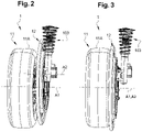
- This device 13 allows said railway wheel 12 to be driven between the passive position illustrated in figure 1 and 2 , and the active position shown in picture 3 .
- the railway wheel 12 in the passive position the railway wheel 12 is decoupled in rotation from the road wheel 11 and the second axis of rotation A2 is eccentric with respect to the first axis of rotation A1, whereas in the active position the railway wheel 12 is coupled in rotation to the road wheel 11 and the second axis of rotation A2 is coaxial with the first axis of rotation A1.
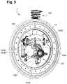
- the rail-road rolling member 1 of the figure 1 devoid of the fixing yoke 104, of the transmission shaft 101 and of the road wheel 11, this in order to better represent the device 13 for supporting and driving said railway wheel 12.
- the hub 102 of the vehicle is secured in a fixed manner to the suspension 103 of the axle via a first fixing lug 102A.
- a second fixing lug 102B of the hub 102 makes it possible to secure it to the fixing yoke 104.
- the device 13 for supporting and driving said railway wheel 12 comprises a guide mechanism 14 for the railway wheel 12 between its active and passive positions, where the guide mechanism 14 is controlled by an electric motor 15.
- the guide mechanism 14 further comprises a support 140, here a support plate 140 forming a handle, provided to be integral in a fixed manner with the hub 102 and comprising two branches 140A, 140B, one branch 140B of which is extended by a extension 140B1 to be connected to a side fixing lug 102C, called the third lug 102C, of the hub 102.
- a support 140 here a support plate 140 forming a handle, provided to be integral in a fixed manner with the hub 102 and comprising two branches 140A, 140B, one branch 140B of which is extended by a extension 140B1 to be connected to a side fixing lug 102C, called the third lug 102C, of the hub 102.
- the guide mechanism 14 comprises a rotating shaft 141 fixed free in rotation on the support 140 around a third axis of rotation A3.
- the fixing of the rotating shaft 141 to the support 140 is carried out by means of bearings 141A, here two bearings 141A, guiding the rotating shaft 141 in rotation around the third axis of rotation A3.
- the third axis of rotation A3 is perpendicular to the first and second axes of rotation A1, A2.
- the rotating shaft 141 comprises at its ends guide arms 16 of the railway wheel 12, in this case two guide arms 16.
- Said extension 140B1 of the arm of the support 140 comprises another bearing 141A on which is mounted free in rotation, around a fourth axis of rotation A4, an auxiliary guide arm 16 .
- the free end of this auxiliary guide arm 16 is secured both to a fixing bracket 12A for the railway wheel 12, and to a connecting rod 17 fixed to the end of one of the other arms of guide 16 connected to the rotating shaft 141.
- the fourth axis of rotation A4 is parallel to the third axis of rotation A3.
- the fixing brackets 12A and the guide arms 16 form attachment points of the railway wheel 12 to the guide mechanism 14.
- the use of three attachment points allows a stable hold of the railway wheel 12, as well as the maintaining its parallelism with respect to the road wheel 11.
- the guide arms 16 form a lever with respect to the rotating shaft 141 making it possible to bring the railway wheel 12 alternately to the passive position or to the active position.
- the rotating shaft 141 is driven using a motion conversion mechanism 18 provided to convert a rotational movement perpendicular to the third axis of rotation A3 into a rotational movement of the rotating shaft 141 around said third axis A3 .
- bevel gears 18A, 18B, also called concurrent, are provided, the output bevel gear 18B of which is coupled in rotation to the rotating shaft 141.
- the input bevel gear 18a is rotationally coupled by its input shaft 18A1 to an electric motor 15.
- the railway wheel 12 includes an inner crown 121 and an outer crown 122.
- the inner crown 121 is integral with the device 13 for supporting and driving said railway wheel 12. More particularly, the inner crown 121 is connected to said device 13 via the fixing brackets 12A integral with the inner crown 121 and comprising at their end rings 12A1 on which are mounted free in rotation pins 16A of the guide arms 16 disposed at their end.
- the outer crown 122 ensures the coupling of the railway wheel 12 to the road wheel 11. Furthermore, the outer crown 122 is equipped with a bead 122A on its periphery suitable for running on rails.
- the railway wheel 12 has an outer diameter greater than the outer diameter of the road wheel 11.
- the outer ring 122 of the railway wheel 12 extends radially beyond the road wheel 11.
- a rolling mechanism 123 here a set of balls, interposed between the inner ring 121 and the outer ring 122 allows rotational uncoupling of the inner and outer rings 121, 122 relative to each other. other.
- the rolling member 1 In a driving mode on the road, the rolling member 1 is in a configuration illustrated in figure 2 , where the railway wheel 12 is decoupled in rotation from the road wheel 11.
- the position of the rotating shaft 141 is that of the figure 8 , where the guide arms 16 forming a lever separate the railway wheel 12 from the road wheel 11.
- the railway wheel 12 is then raised relative to the road wheel 11, and the vehicle can move forward on the road.
- the vehicle In a mode of driving on rails, the vehicle is of course previously positioned in correspondence of the rails to allow the engagement of the vehicle on the latter, a platform can be provided for this purpose to raise the vehicle thus allowing the deployment of the railway wheels 12 in active position.
- the electric motor 15 is activated then driving the rotation of the input shaft 18A1 of the motion conversion mechanism 18.
- the input gear 18A whose teeth are engaged with the teeth of the output gear 18B therefore drives the output gear 18B in rotation.
- the rotation of the output gear 18B rotates the rotating shaft 141.
- the rotating shaft 141 then causes the rotational movement of the two guide arms 16 integral with the rotating shaft 141, as well as the rotational movement of the third guide arm 16 actuated by the two guide arms 16 linked to the rotating shaft 141 via the connecting rod 17.
- the guide arms 16 then cause the movement of the railway wheel 12 from its passive position to its active position corresponding to a rotation of the rotating shaft 141 through an angle equal to 160°.
- the orientation of the guide arms 16 in the active position corresponds to the configuration illustrated in figure 9 , and where the outer crown 122 of the railway wheel 12 is pressed against a tire 11A of the road wheel 11 to ensure the coupling of the railway wheel 12 to the road wheel 11.
- the guide arms 16 then keep the outer crown 122 pressed against the tire 11A to ensure this coupling in continuous rotation.
- flange 122A of railway wheel 12 of rolling member 1 is then engaged on the rails, while road wheel 11 is seated on the roadway comprising the rails.
- the seat of the vehicle is ensured by the road wheels 11 only, the railway wheels 12 engaged on the rails having the function of guiding the vehicle on them.
- the road wheels 11 of the vehicle then cause the vehicle to move forward on the roadway comprising the rails.
- the outer crown 122 of the railway wheel 12 is then driven in rotation by the kinetic energy of the road wheel 11.
- the balls of the rolling mechanism 123 allow the rotational decoupling of the outer crown 122 with respect to the inner crown 121 so that only the outer crown 122 is driven in rotation by the road wheel 11.
- the outer crown 122 then guides the vehicle on the rails.
- the electric motor 15 is driven in rotation in the opposite direction to disengage the railway wheels 12 from the rails and bring them into the passive position illustrated in picture 2 .
- the platform provided for engaging the vehicle on the rails also makes it possible to raise the vehicle and then ensure the disengagement bringing the railway wheels 12 into the passive position.
Abstract
L'invention concerne un organe de roulement (1) rail-route pour véhicule, comprenant une roue routière (11) montée sur un essieu du véhicule autour d'un premier axe de rotation (A1),
l'organe de roulement (1) comprenant :
une roue ferroviaire (12) de guidage du véhicule sur rails, de révolution autour d'un deuxième axe de rotation (A2),
un dispositif (13) de support et d'entraînement de ladite roue ferroviaire (12), configuré pour entraîner ladite roue ferroviaire (12) entre :
une position passive où la roue ferroviaire (12) est découplée en rotation de la roue routière (11) et où le deuxième axe de rotation (A2) est excentré par rapport au premier axe de rotation (A1) ; et
une position active où la roue ferroviaire (12) est couplée à la roue routière (11) et où le deuxième axe de rotation (A2) est coaxial au premier axe de rotation (A1).

the running gear (1) comprising:
a railway wheel (12) for guiding the vehicle on rails, of revolution around a second axis of rotation (A2),
a device (13) for supporting and driving said railway wheel (12), configured to drive said railway wheel (12) between:
a passive position where the railway wheel (12) is decoupled in rotation from the road wheel (11) and where the second axis of rotation (A2) is eccentric with respect to the first axis of rotation (A1); and
an active position where the railway wheel (12) is coupled to the road wheel (11) and where the second axis of rotation (A2) is coaxial with the first axis of rotation (A1).
Description
La présente invention concerne le domaine des véhicules automobiles rail-route pouvant transiter alternativement entre un mode de conduite sur route et un mode de conduite sur rails. Elle concerne plus particulièrement un organe de roulement rail-route, ainsi qu'un essieu de véhicule automobile comprenant un tel organe de roulement.The present invention relates to the field of road-rail motor vehicles which can transit alternately between a driving mode on the road and a driving mode on rails. It relates more particularly to a rail-road rolling member, as well as a motor vehicle axle comprising such a rolling member.
Il est connu des véhicules prévus pour une conduite alternativement sur route ou sur rails. Pour cela, ces véhicules sont équipés de roues routières et de roues ferroviaires adaptées à cette transition.Vehicles designed for driving alternately on the road or on rails are known. For this, these vehicles are equipped with road wheels and rail wheels adapted to this transition.
La transition d'un mode de conduite sur route vers un mode de conduite sur rails doit permettre d'assurer le couplage des roues ferroviaires avec les rails d'une ligne ferroviaire, alors que la transition d'un mode de conduite sur rails vers un mode de conduite sur route doit permettre d'assurer la mise sur route du véhicule.The transition from a driving mode on the road to a driving mode on rails must make it possible to ensure the coupling of the railway wheels with the rails of a railway line, whereas the transition from a driving mode on rails to a mode of driving on the road must make it possible to ensure the setting on the road of the vehicle.
Dans l'état de la technique connue, un tel véhicule automobile comprend des roues ferroviaires et des roues routières distinctes les unes des autres de sorte que les roues ferroviaires ou les roues routières sont montées sur des essieux de véhicule de façon articulées pour permettre leur déploiement ou leur rétractation. Il est ainsi possible de configurer le véhicule pour une conduite sur rails ou alternativement sur route.In the state of the known art, such a motor vehicle comprises railway wheels and road wheels separate from each other so that the railway wheels or the road wheels are mounted on vehicle axles in an articulated manner to allow their deployment or their withdrawal. It is thus possible to configure the vehicle for driving on rails or alternatively on the road.
Ce type de véhicule nécessite toutefois de prévoir des essieux supplémentaires pour supporter les roues ferroviaires. Le châssis du véhicule, ainsi que la motorisation du véhicule se trouvent alors mécaniquement complexes à réaliser.However, this type of vehicle requires the provision of additional axles to support the railway wheels. The chassis of the vehicle, as well as the engine of the vehicle are then mechanically complex to produce.
L'invention a pour objectif de palier au moins l'un des inconvénients cités en proposant entre autres l'amélioration d'un organe de roulement pour un tel véhicule automobile. A cet effet, l'invention a pour objet un organe de roulement rail-route pour véhicule, comprenant une roue routière destinée à être montée en rotation sur un essieu du véhicule autour d'un premier axe de rotation,
- l'organe de roulement comprenant en outre :
- une roue ferroviaire de guidage du véhicule sur rails, la roue ferroviaire étant de révolution autour d'un deuxième axe de rotation,
- un dispositif de support et d'entraînement de ladite roue ferroviaire,
- ledit dispositif étant configuré pour entraîner ladite roue ferroviaire entre :
- une position passive dans laquelle la roue ferroviaire est découplée en rotation de la roue routière et dans laquelle le deuxième axe de rotation est excentré par rapport au premier axe de rotation ; et
- une position active dans laquelle la roue ferroviaire est couplée en rotation à la roue routière et dans laquelle le deuxième axe de rotation est coaxial par rapport au premier axe de rotation.
- the running gear further comprising:
- a railway wheel for guiding the vehicle on rails, the railway wheel being of revolution about a second axis of rotation,
- a device for supporting and driving said railway wheel,
- said device being configured to drive said railway wheel between:
- a passive position in which the railway wheel is decoupled in rotation from the road wheel and in which the second axis of rotation is eccentric with respect to the first axis of rotation; and
- an active position in which the railway wheel is coupled in rotation to the road wheel and in which the second axis of rotation is coaxial with the first axis of rotation.
La configuration de l'organe de roulement selon l'invention évite l'utilisation d'essieux distincts dédiés aux roues routières et aux roues ferroviaires. L'organe de roulement forme un couple roue routière/roue ferroviaire dont la transition rails/route est facilitée par l'articulation de la roue ferroviaire à l'aide de dispositif de support et d'entraînement pour amener la roue ferroviaire entre une position concentrique avec l'axe de rotation de l'essieu et une position excentrique par rapport à ce même axe de rotation de l'essieu.The configuration of the running gear according to the invention avoids the use of separate axles dedicated to road wheels and railway wheels. The rolling member forms a road wheel/railway wheel pair, the rail/road transition of which is facilitated by the articulation of the railroad wheel using a support and drive device to bring the railroad wheel between a concentric position with the axis of rotation of the axle and an eccentric position with respect to this same axis of rotation of the axle.
On comprendra que la position concentrique correspond à la position active, en l'occurrence à une conduite sur rails, alors que la position excentrique correspond à la position passive, en l'occurrence à une conduite sur route.It will be understood that the concentric position corresponds to the active position, in this case to driving on rails, whereas the eccentric position corresponds to the passive position, in this case to driving on the road.
Selon un mode de réalisation de l'invention, la roue ferroviaire comprend une couronne intérieure solidaire du dispositif de support et d'entraînement de ladite roue ferroviaire, et une couronne extérieure assurant le couplage de la roue ferroviaire à la roue routière, la couronne intérieure et la couronne extérieure étant découplées en rotation l'une de l'autre par l'intermédiaire d'un mécanisme de roulement.According to one embodiment of the invention, the railway wheel comprises an inner ring integral with the device for supporting and driving said railway wheel, and an outer ring ensuring the coupling of the railway wheel to the road wheel, the inner ring and the outer ring being rotationally decoupled from each other via a rolling mechanism.
Une telle roue ferroviaire permet avantageusement la récupération de l'énergie cinétique de la roue routière pour l'entraînement de la roue ferroviaire.Such a railway wheel advantageously allows the recovery of the kinetic energy of the road wheel for driving the railway wheel.
Selon une variante de réalisation de l'invention, dans la position active la couronne extérieure est pressée contre un pneumatique de la roue routière pour assurer le couplage de la roue ferroviaire à la roue routière.According to a variant embodiment of the invention, in the active position the outer rim is pressed against a tire of the road wheel to ensure the coupling of the railway wheel to the road wheel.
On comprendra par exemple par l'expression « pressé contre » qu'un élément est couplé par friction à un autre élément.It will be understood for example by the expression “pressed against” that an element is coupled by friction to another element.
Le couplage en rotation de la couronne extérieure au pneumatique de la roue routière assure avantageusement une grande surface de contact permettant une plus grande transmission de l'énergie cinétique de la roue routière.The coupling in rotation of the outer crown to the tire of the road wheel advantageously provides a large contact surface allowing greater transmission of the kinetic energy of the road wheel.
Alternativement, dans la position active la couronne extérieure est pressée contre une jante de la roue ferroviaire pour assurer le couplage de la roue ferroviaire à la roue routière.Alternatively, in the active position the outer crown is pressed against a rim of the railway wheel to ensure the coupling of the railway wheel to the road wheel.
Un tel couplage de la couronne extérieure permet la récupération de l'énergie cinétique depuis un élément mécanique, en l'occurrence la jante, directement couplé à l'essieu du véhicule.Such coupling of the outer crown allows the recovery of kinetic energy from a mechanical element, in this case the rim, directly coupled to the axle of the vehicle.
Selon un mode de réalisation de l'invention, le dispositif de support et d'entraînement de ladite roue ferroviaire comprend un mécanisme de guidage de la roue ferroviaire comportant un support fixe prévu pour être solidaire de l'essieu et sur lequel est monté un arbre tournant autour d'un troisième axe de rotation portant à ses extrémités des bras de guidage de la roue ferroviaire. Les bras de guidage peuvent alors supporter la roue ferroviaire.According to one embodiment of the invention, the device for supporting and driving said railway wheel comprises a mechanism for guiding the railway wheel comprising a fixed support provided to be integral with the axle and on which is mounted a shaft rotating around a third axis of rotation carrying at its ends guide arms of the rail wheel. The guide arms can then support the railway wheel.
Les bras de guidage ont pour effet de supporter et guider la roue ferroviaire entre la position dite passive et la position dite active. Plus particulièrement, l'entraînement en rotation des bras de guidage permet de guider selon une portion circulaire la roue ferroviaire par rapport à la roue routière entre la position passive et la position active. La portion circulaire correspondant approximativement à une rotation de l'arbre tournant d'un angle de 160°.The guide arms have the effect of supporting and guiding the railway wheel between the so-called passive position and the so-called active position. More particularly, the rotational drive of the guide arms makes it possible to guide the railway wheel along a circular portion with respect to the road wheel between the passive position and the active position. The circular portion corresponds approximately to a rotation of the rotating shaft through an angle of 160°.
Selon un mode de réalisation de l'invention, le mécanisme de guidage et d'entraînement comprend en outre un bras de guidage auxiliaire en rotation autour d'un quatrième axe de rotation excentré par rapport au troisième axe de rotation.According to one embodiment of the invention, the guide and drive mechanism further comprises an auxiliary guide arm rotating around a fourth axis of rotation eccentric with respect to the third axis of rotation.
Le bras de guidage auxiliaire peut être un autre bras de guidage qui est auxiliaire, le bras de guidage auxiliaire supportant également la roue ferroviaire pour la guider.The auxiliary guide arm may be another guide arm which is auxiliary, the auxiliary guide arm also supporting the railway wheel to guide it.
Selon un mode de réalisation de l'invention, le mécanisme de guidage comprend un mécanisme de conversion de mouvement prévu pour convertir un mouvement de rotation perpendiculaire au troisième axe de rotation en un mouvement de rotation de l'arbre tournant autour dudit troisième axe.According to one embodiment of the invention, the guide mechanism comprises a movement conversion mechanism designed to convert a rotational movement perpendicular to the third axis of rotation into a rotational movement of the shaft rotating around said third axis.
Un tel mécanisme de conversion de mouvement a pour fait la réduction de son encombrement, celui-ci étant supporté par l'essieu du véhicule.Such a movement conversion mechanism has the effect of reducing its size, the latter being supported by the axle of the vehicle.
Selon un mode de réalisation de l'invention, le mécanisme de conversion de mouvement est formé par des engrenages coniques, dont l'engrenage de sortie est couplé en rotation à l'arbre tournant.According to one embodiment of the invention, the motion conversion mechanism is formed by bevel gears, the output gear of which is rotationally coupled to the rotating shaft.
Selon un mode de réalisation de l'invention, le mécanisme de conversion de mouvement est entraîné par un moteur électrique.According to one embodiment of the invention, the motion conversion mechanism is driven by an electric motor.
Le moteur directement couplé à la roue du mécanisme de conversion de mouvement réduit la puissance nécessaire à cet entraînement.The motor directly coupled to the wheel of the motion conversion mechanism reduces the power required for this drive.
Par ailleurs, l'invention concerne un essieu de véhicule comprenant un organe de roulement tel que défini précédemment.Furthermore, the invention relates to a vehicle axle comprising a rolling member as defined above.
Selon un mode de réalisation, l'essieu comprend une suspension à laquelle est solidarisé le dispositif de support et d'entraînement de ladite roue ferroviaire.According to one embodiment, the axle comprises a suspension to which the device for supporting and driving said railway wheel is secured.
Selon un mode de réalisation, la roue routière est portée par un moyeu configuré pour être relié à un arbre de transmission du véhicule.According to one embodiment, the road wheel is carried by a hub configured to be connected to a transmission shaft of the vehicle.
D'autres caractéristiques et avantages de l'invention apparaîtront à la lecture de la description nullement limitative qui suit et des figures annexées qui illustrent de manière schématique plusieurs modes de réalisation de l'invention.
- [
Fig. 1 ] représente une vue en perspective d'un organe de roulement monté sur un essieu d'un véhicule, l'organe de roulement comprenant une roue routière et une roue ferroviaire rétractable à l'aide d'un dispositif de support et d'entraînement. - [
Fig. 2 ] représente une vue de côté de l'organe de roulement de lafigure 1 dans une position passive adaptée à une conduite sur route. - [
Fig. 3 ] représente une vue de côté de l'organe de roulement de lafigure 1 dans une position active adaptée à une conduite sur rails. - [
Fig. 4 ] représente une vue en perspective de l'organe de roulement où l'essieu a été retiré. - [
Fig. 5 ] représente une vue arrière de l'organe de roulement de lafigure 4 . - [
Fig. 6 ] est une vue en perspective de la roue ferroviaire. - [
Fig. 7 ] est une vue en perspective d'une section de la roue ferroviaire représentée à lafigure 6 . - [
Fig. 8 ] est une vue en perspective du dispositif de support et d'entraînement tel que monté sur l'essieu et où le dispositif est représenté dans une position dite passive de l'organe de roulement. - [
Fig. 9 ] est une vue en perspective du dispositif de support et d'entraînement seul représenté dans une position dite active de l'organe de roulement.
- [
Fig. 1 ] shows a perspective view of a rolling member mounted on an axle of a vehicle, the rolling member comprising a road wheel and a retractable railway wheel using a support and drive device. - [
Fig. 2 ] shows a side view of the running gear of thefigure 1 in a passive position suitable for driving on the road. - [
Fig. 3 ] shows a side view of the running gear of thefigure 1 in an active position suitable for driving on rails. - [
Fig. 4 ] shows a perspective view of the running gear where the axle has been removed. - [
Fig. 5 ] shows a rear view of the running gear of thefigure 4 . - [
Fig. 6 ] is a perspective view of the railway wheel. - [
Fig. 7 ] is a perspective view of a section of the railway wheel shown infigure 6 . - [
Fig. 8 ] is a perspective view of the support and drive device as mounted on the axle and where the device is shown in a so-called passive position of the running gear. - [
Fig. 9 ] is a perspective view of the support and drive device alone shown in a so-called active position of the running gear.
En se référant à la
L'essieu est représenté ici comprend un arbre de transmission 101, un moyeu 102 recevant l'arbre de transmission 101, une suspension 103 fixée au moyeu 102 et une chape de fixation 104 prévue pour relier le moyeu 102 à un châssis du véhicule.The axle shown here comprises a
Dans la suite de la description on décrira un seul organe de roulement 1. Bien entendu, le véhicule est équipé de plusieurs organes de roulement 1. Ainsi, on comprendra que la description de plusieurs roues routière 11 ou plusieurs roues ferroviaires 12 fait référence à un véhicule équipé de plusieurs organes de roulement 1.In the remainder of the description, a single rolling
L'organe de roulement 1 rail-route comprend une roue routière 11 et une roue ferroviaire 12 assemblées l'une à l'autre de façon mobile.The road-
La roue routière 11 permet une conduite du véhicule sur route, alors que la roue ferroviaire 12 permet une conduite sur rails.The
La roue routière 11 est montée en rotation sur le moyeu 102 de l'essieu autour d'un premier axe de rotation A1.The
En se référant à la
En se référant à la
On comprendra particulièrement que dans la position passive et active de l'organe de roulement 1, l'assise du véhicule au sol est toujours réalisée par la roue routière 11. En d'autres termes, en conduite sur route ou bien en conduite sur rails, le véhicule est toujours guidé en traction au sol par la roue routière 11. Dans la position active, la roue ferroviaire 12 assure uniquement le guidage du véhicule sur les rails.It will be particularly understood that in the passive and active position of the
En se référant aux
De façon notable, l'organe de roulement 1 est équipé d'un dispositif 13 de support et d'entraînement de ladite roue ferroviaire 12.Notably, the rolling
Ce dispositif 13 permet l'entrainement de ladite roue ferroviaire 12 entre la position passive illustrée aux
Plus particulièrement, dans la position passive la roue ferroviaire 12 est découplée en rotation de la roue routière 11 et le deuxième axe de rotation A2 est excentré par rapport au premier axe de rotation A1, alors que dans la position active la roue ferroviaire 12 est couplée en rotation à la roue routière 11 et le deuxième axe de rotation A2 est coaxial par rapport au premier axe de rotation A1.More particularly, in the passive position the
En se référant aux
Le moyeu 102 du véhicule est solidarisé de façon fixe à la suspension 103 de l'essieu par l'intermédiaire d'une première patte de fixation 102A. Une deuxième patte de fixation 102B du moyeu 102 permet de le solidariser à la chape de fixation 104.The
Le dispositif 13 de support et d'entraînement de ladite roue ferroviaire 12 comprend un mécanisme de guidage 14 de la roue ferroviaire 12 entre ses positions active et passive, où le mécanisme de guidage 14 est commandé par un moteur électrique 15.The
Le mécanisme de guidage 14 comprend, par ailleurs, un support 140, ici une plaque de support 140 formant une anse, prévue pour être solidaire de façon fixe au moyeu 102 et comprenant deux branches 140A, 140B, dont une branche 140B se prolonge par une extension 140B1 pour être reliée à une patte de fixation latérale 102C, dite troisième patte 102C, du moyeu 102.The
En outre, le mécanisme de guidage 14 comprend un arbre tournant 141 fixé libre en rotation sur le support 140 autour d'un troisième axe de rotation A3. La fixation de l'arbre tournant 141 au support 140 est réalisée par l'intermédiaire de paliers 141A, ici deux paliers 141A, guidant l'arbre tournant 141 en rotation autour du troisième axe de rotation A3.In addition, the
Le troisième axe de rotation A3 est perpendiculaire au premier et deuxième axes de rotation A1, A2.The third axis of rotation A3 is perpendicular to the first and second axes of rotation A1, A2.
L'arbre tournant 141 comprend à ses extrémités des bras de guidage 16 de la roue ferroviaire 12, en l'occurrence deux bras de guidage 16.The
Ces bras de guidage 16 sont fixes par rapport à l'arbre tournant 141 et solidaires des équerres de fixation 12A de la roue ferroviaire 12.These guide
Ladite extension 140B1 de la branche du support 140 comprend un autre palier 141A sur lequel est monté libre en rotation, autour d'un quatrième axe de rotation A4, un bras de guidage 16 auxiliaire. L'extrémité libre de ce bras de guidage 16 auxiliaire est solidaire, à la fois d'une équerre de fixation 12A de la roue ferroviaire 12, et d'une tige de raccordement 17 fixée à l'extrémité d'un des autres bras de guidage 16 relié à l'arbre tournant 141.Said extension 140B1 of the arm of the
Le quatrième axe de rotation A4 est parallèle au troisième axe de rotation A3.The fourth axis of rotation A4 is parallel to the third axis of rotation A3.
L'entraînement en rotation des bras de guidage 16 reliés à l'arbre tournant 141 entraîne la rotation du bras de guidage 16 auxiliaire par l'intermédiaire de la tige de raccordement 17.The rotational drive of the
Les équerres de fixation 12A et les bras de guidage 16 forment des points d'attache de la roue ferroviaire 12 au mécanisme de guidage 14. L'utilisation de trois points d'attache permet un maintien stable de la roue ferroviaire 12, ainsi que le maintien de son parallélisme par rapport à la roue routière 11.The fixing
Les bras de guidage 16 forment un levier par rapport à l'arbre tournant 141 permettant d'amener la roue ferroviaire 12 alternativement à la position passive ou à la position active.The
L'arbre tournant 141 est entraîné à l'aide d'un mécanisme de conversion de mouvement 18 prévu pour convertir un mouvement de rotation perpendiculaire au troisième axe de rotation A3 en un mouvement de rotation de l'arbre tournant 141 autour dudit troisième axe A3.The
A cet effet, il est prévu des engrenages coniques 18A, 18B, dit aussi concourants, dont l'engrenage conique de sortie 18B est couplé en rotation de l'arbre tournant 141.For this purpose,
L'engrenage conique d'entrée 18a est couplé en rotation par son arbre d'entrée 18A1 à un moteur électrique 15.The input bevel gear 18a is rotationally coupled by its input shaft 18A1 to an
Bien entendu, le moteur électrique 15est fixe par rapport au support 14Of course, the
En se référant aux
Tel que représenté, la roue ferroviaire 12 comprend une couronne intérieure 121 et une couronne extérieure 122.As shown, the
La couronne intérieure 121 est solidaire du dispositif 13 de support et d'entraînement de ladite roue ferroviaire 12. Plus particulièrement, la couronne intérieure 121 est reliée audit dispositif 13 par l'intermédiaire des équerres de fixation 12A solidaire de la couronne intérieure 121 et comportant à leur extrémité des bagues 12A1 sur lesquelles sont montées libre en rotation des pions 16A des bras de guidage 16 disposés à leur extrémité.The
La couronne extérieure 122 assure le couplage de la roue ferroviaire 12 à la roue routière 11. Par ailleurs, la couronne extérieure 122 est équipée d'un boudin 122A sur son pourtour adapté à la circulation sur rails.The
On notera particulièrement que la roue ferroviaire 12 présente un diamètre extérieur supérieur au diamètre extérieur de la roue routière 11. En l'occurrence, dans la position active de l'organe de roulement 1, c'est-à-dire lorsque la roue routière 11 et la roue ferroviaire 12 sont coaxiales, la couronne extérieure 122 de la roue ferroviaire 12 s'étend radialement au-delà de la roue routière 11.It will be particularly noted that the
Il convient de noter qu'un mécanisme de roulement 123, ici un ensemble de billes, intercalé entre la couronne intérieure 121 et la couronne extérieure 122 permet un découplage en rotation des couronnes intérieure et extérieure 121, 122 l'une par rapport à l'autre.It should be noted that a
On va maintenant décrire plus particulièrement le fonctionnement de l'organe de roulement 1.We will now describe more particularly the operation of the
Dans un mode de conduite sur route, l'organe de roulement 1 se trouve dans une configuration illustrée à la
La roue ferroviaire 12 est alors relevée par rapport à la roue routière 11, et le véhicule peut avancer sur la route.The
Dans un mode de conduite sur rails, le véhicule est bien entendu préalablement positionné en correspondance des rails pour permettre l'engagement du véhicule sur ces dernières, une plateforme peut être prévu à cet effet pour surélever le véhicule permettant ainsi le déploiement des roues ferroviaires 12 dans la position active.In a mode of driving on rails, the vehicle is of course previously positioned in correspondence of the rails to allow the engagement of the vehicle on the latter, a platform can be provided for this purpose to raise the vehicle thus allowing the deployment of the
Une fois le véhicule positionné au-dessus des rails, le moteur électrique 15 est activé entraînant alors la rotation de l'arbre d'entrée 18A1 du mécanisme de conversion de mouvement 18. L'engrenage d'entrée 18A dont la denture est engagée avec la denture de l'engrange de sortie 18B entraîne par conséquent l'engrange de sortie 18B en rotation.Once the vehicle is positioned above the rails, the
La rotation du l'engrenage de sortie 18B met en rotation l'arbre tournant 141. L'arbre tournant 141 entraîne alors le déplacement en rotation des deux bras de guidage 16 solidaires de l'arbre tournant 141, ainsi que le déplacement en rotation du troisième bras de guidage 16 actionné par les deux bras de guidage 16 liés à l'arbre tournant 141 par l'intermédiaire de la tige de raccordement 17.The rotation of the
On comprendra que le mouvement de ces bras de guidage 16 est synchronisé par rapport à la rotation de l'arbre tournant 141.It will be understood that the movement of these guide
Les bras de guidage 16 entraînent alors le déplacement de la roue ferroviaire 12 de sa position passive vers sa position active correspondant à une rotation de l'arbre tournant 141 d'un angle égal à 160°.The
L'orientation des bras de guidage 16 dans la position active correspond à la configuration illustrée à la
Les bras de guidage 16 maintiennent alors pressés la couronne extérieure 122 contre le pneumatique 11A pour assurer ce couplage en rotation en continu.The
On comprendra que le couple généré sur l'arbre tournant 141 nécessaire à ce couplage en rotation est fourni par le moteur électrique 15.It will be understood that the torque generated on the
Dans la position active de l'organe de roulement 1, le boudin 122A de la roue ferroviaire 12 de l'organe de roulement 1 est alors engagé sur les rails, alors que la roue routière 11 est assise sur la chaussée comprenant les rails. Ainsi, l'assise du véhicule est assurée par les roues routières 11 uniquement, les roues ferroviaires 12 engagées sur les rails ayant pour fonction de guider le véhicule sur celles-ci.In the active position of rolling
Les roues routières 11 du véhicule entraînent alors le véhicule pour son avancée sur la chaussée comprenant les rails.The
La couronne extérieure 122 de la roue ferroviaire 12 est alors entraînée en rotation par l'énergie cinétique de la roue routière 11.The
Les billes du mécanisme de roulement 123 permettent le découplage en rotation de la couronne extérieure 122 par rapport à la couronne intérieure 121 de sorte que seule la couronne extérieure 122 est entraînée en rotation par la roue routière 11.The balls of the
La couronne extérieure 122 guide alors le véhicule sur les rails.The
Lorsqu'il est nécessaire de transiter le véhicule vers un mode de conduite sur route, le moteur électrique 15 est entraîné en rotation en sens inverse pour désengager les roues ferroviaires 12 des rails et les amener dans la position passive illustrée à la
A cet effet, la plateforme prévue pour engager le véhicule sur les rails permet également de surélever le véhicule et alors assurer le désengagement amenant les roues ferroviaires 12 dans la position passive.To this end, the platform provided for engaging the vehicle on the rails also makes it possible to raise the vehicle and then ensure the disengagement bringing the
Bien évidemment, l'invention n'est pas limitée aux exemples qui viennent d'être décrits et de nombreux aménagements peuvent être apportés à ces exemples sans sortir du cadre de l'invention. Notamment, les différentes caractéristiques, formes, variantes et modes de réalisation de l'invention peuvent être associés les uns avec les autres selon diverses combinaisons dans la mesure où ils ne sont pas incompatibles ou exclusifs les uns des autres. En particulier, toutes les variantes et modes de réalisation décrits précédemment sont combinables entre eux.Of course, the invention is not limited to the examples which have just been described and many adjustments can be made to these examples without departing from the scope of the invention. In particular, the different characteristics, forms, variants and embodiments of the invention can be associated with each other in various combinations insofar as they are not incompatible or exclusive of each other. In particular, all the variants and embodiments described previously can be combined with each other.
Claims (10)
Applications Claiming Priority (1)
| Application Number | Priority Date | Filing Date | Title |
|---|---|---|---|
| FR2011881A FR3116233A1 (en) | 2020-11-19 | 2020-11-19 | Improved road-rail running gear |
Publications (1)
| Publication Number | Publication Date |
|---|---|
| EP4000968A1 true EP4000968A1 (en) | 2022-05-25 |
Family
ID=74553980
Family Applications (1)
| Application Number | Title | Priority Date | Filing Date |
|---|---|---|---|
| EP21209372.8A Pending EP4000968A1 (en) | 2020-11-19 | 2021-11-19 | Improved rail-road rolling member |
Country Status (2)
| Country | Link |
|---|---|
| EP (1) | EP4000968A1 (en) |
| FR (1) | FR3116233A1 (en) |
Citations (4)
| Publication number | Priority date | Publication date | Assignee | Title |
|---|---|---|---|---|
| BE379301A (en) * | ||||
| FR1171550A (en) * | 1957-01-25 | 1959-01-27 | Chesapeake & Ohio Railway | Improvements to vehicles that can run on road and on rails |
| NL2000331C2 (en) * | 2006-11-23 | 2008-05-26 | Movares Nederland Bv | Combi wheel for bimodal vehicle, has rail and road wheels with adjustable rotation axes positioned eccentrically to each other and to their axle |
| FR3043947A1 (en) * | 2015-11-19 | 2017-05-26 | Soc Des Anciens Etablissements L Geismar | MOBILE VEHICLE ON THE GROUND AND ON A RAILWAY |
-
2020
- 2020-11-19 FR FR2011881A patent/FR3116233A1/en active Pending
-
2021
- 2021-11-19 EP EP21209372.8A patent/EP4000968A1/en active Pending
Patent Citations (4)
| Publication number | Priority date | Publication date | Assignee | Title |
|---|---|---|---|---|
| BE379301A (en) * | ||||
| FR1171550A (en) * | 1957-01-25 | 1959-01-27 | Chesapeake & Ohio Railway | Improvements to vehicles that can run on road and on rails |
| NL2000331C2 (en) * | 2006-11-23 | 2008-05-26 | Movares Nederland Bv | Combi wheel for bimodal vehicle, has rail and road wheels with adjustable rotation axes positioned eccentrically to each other and to their axle |
| FR3043947A1 (en) * | 2015-11-19 | 2017-05-26 | Soc Des Anciens Etablissements L Geismar | MOBILE VEHICLE ON THE GROUND AND ON A RAILWAY |
Also Published As
| Publication number | Publication date |
|---|---|
| FR3116233A1 (en) | 2022-05-20 |
Similar Documents
| Publication | Publication Date | Title |
|---|---|---|
| EP2512855B1 (en) | Motorised hub with coupling/decoupling means | |
| CA2725739C (en) | Wheel and brake assembly for aircraft equipped with a device for rotating and holding | |
| EP2543590B1 (en) | System for electric motorisation of a wheel | |
| EP0525663B1 (en) | Wheel unit with motor, especially for vehicles | |
| EP0414814B1 (en) | Wheel for a motor vehicle or towed vehicle and vehicule fitted with said wheel | |
| CA2777609A1 (en) | Rotating device coupling a ring to a wheel as well as the aircraft landing gear equipped with such a device | |
| EP2883774B1 (en) | Motor bogie for a rail vehicle in which the motor is substantially coaxial with the wheel axle | |
| EP1667885A1 (en) | System for guiding a vehicle along at least one guiding rail | |
| EP4000968A1 (en) | Improved rail-road rolling member | |
| EP0241377A1 (en) | Removable power unit and associated vehicle such as a golf caddy | |
| FR3064590A1 (en) | PENDULUM VEHICLE WITH INCLINATION BLOCKING ARRANGEMENTS | |
| FR2534213A1 (en) | TRACTOR OR SIMILAR VEHICLE HAVING DRIVE AND STEERING WHEELS CONTROLLED BY ROCKETS | |
| FR2984243A1 (en) | MOTORIZED HUB FOR THE ELECTRIC MOTORIZATION OF AN AXLE OF A HYBRID TRACTION VEHICLE | |
| EP3395640B1 (en) | Bogie for a railway vehicle comprising braking system comprising three brake disks arranged in between the axle bearings | |
| EP2066537A1 (en) | Drive mechanism comprising means for guiding a drive shaft | |
| FR2896469A1 (en) | Steering shaft for steering wheel of motor vehicle, has helicoidal compression spring arranged on countershaft, exerting axial force defined on upper and lower pinions of countershaft so that pinions tend to move away from one another | |
| EP1896305A1 (en) | Drive mechanism especially for a window wiping device with an elliptical wiping motion | |
| FR2931392A1 (en) | GROUND CONNECTION WITH ELECTRIC SUSPENSION WITH REDUCER, AND APPLICATION | |
| WO2010079375A1 (en) | Device for producing torque, in particular an orientation device | |
| FR2682647A1 (en) | Disengagable drive device for motor vehicle non-driving wheels | |
| FR2689459A1 (en) | Drive for wheels of vehicle - has auxiliary motors driving trailing wheels by friction | |
| EP0112735A1 (en) | Auxiliary manual drive for trailers, especially for caravans | |
| FR3087514A1 (en) | COMPACT MECHANICAL TORQUE SHOCK ABSORBER | |
| FR2619058A1 (en) | Transmission joint for controlling accessories of an internal combustion engine of vehicles | |
| CH419217A (en) | Engine bogie |
Legal Events
| Date | Code | Title | Description |
|---|---|---|---|
| PUAI | Public reference made under article 153(3) epc to a published international application that has entered the european phase |
Free format text: ORIGINAL CODE: 0009012 |
|
| STAA | Information on the status of an ep patent application or granted ep patent |
Free format text: STATUS: THE APPLICATION HAS BEEN PUBLISHED |
|
| AK | Designated contracting states |
Kind code of ref document: A1 Designated state(s): AL AT BE BG CH CY CZ DE DK EE ES FI FR GB GR HR HU IE IS IT LI LT LU LV MC MK MT NL NO PL PT RO RS SE SI SK SM TR |
|
| STAA | Information on the status of an ep patent application or granted ep patent |
Free format text: STATUS: REQUEST FOR EXAMINATION WAS MADE |
|
| 17P | Request for examination filed |
Effective date: 20220922 |
|
| RAV | Requested validation state of the european patent: fee paid |
Extension state: TN Effective date: 20220922 Extension state: MD Effective date: 20220922 Extension state: MA Effective date: 20220922 Extension state: KH Effective date: 20220922 |
|
| RAX | Requested extension states of the european patent have changed |
Extension state: ME Payment date: 20220922 Extension state: BA Payment date: 20220922 |
|
| RBV | Designated contracting states (corrected) |
Designated state(s): AL AT BE BG CH CY CZ DE DK EE ES FI FR GB GR HR HU IE IS IT LI LT LU LV MC MK MT NL NO PL PT RO RS SE SI SK SM TR |