EP4000968A1 - Verbessertes rollorgan für schiene und strasse - Google Patents
Verbessertes rollorgan für schiene und strasse Download PDFInfo
- Publication number
- EP4000968A1 EP4000968A1 EP21209372.8A EP21209372A EP4000968A1 EP 4000968 A1 EP4000968 A1 EP 4000968A1 EP 21209372 A EP21209372 A EP 21209372A EP 4000968 A1 EP4000968 A1 EP 4000968A1
- Authority
- EP
- European Patent Office
- Prior art keywords
- rotation
- road
- wheel
- railway wheel
- axis
- Prior art date
- Legal status (The legal status is an assumption and is not a legal conclusion. Google has not performed a legal analysis and makes no representation as to the accuracy of the status listed.)
- Pending
Links
- 238000005096 rolling process Methods 0.000 title claims description 24
- 230000007246 mechanism Effects 0.000 claims description 25
- 230000033001 locomotion Effects 0.000 claims description 20
- 230000008878 coupling Effects 0.000 claims description 12
- 238000010168 coupling process Methods 0.000 claims description 12
- 238000005859 coupling reaction Methods 0.000 claims description 12
- 238000006243 chemical reaction Methods 0.000 claims description 10
- 239000000725 suspension Substances 0.000 claims description 4
- 230000005540 biological transmission Effects 0.000 description 5
- 230000007704 transition Effects 0.000 description 5
- 230000000694 effects Effects 0.000 description 2
- 238000011084 recovery Methods 0.000 description 2
- 239000011324 bead Substances 0.000 description 1
- 230000006872 improvement Effects 0.000 description 1
- 230000001360 synchronised effect Effects 0.000 description 1
Images


Classifications
-
- B—PERFORMING OPERATIONS; TRANSPORTING
- B60—VEHICLES IN GENERAL
- B60F—VEHICLES FOR USE BOTH ON RAIL AND ON ROAD; AMPHIBIOUS OR LIKE VEHICLES; CONVERTIBLE VEHICLES
- B60F1/00—Vehicles for use both on rail and on road; Conversions therefor
- B60F1/02—Vehicles for use both on rail and on road; Conversions therefor with rail and road wheels on the same axle
-
- B—PERFORMING OPERATIONS; TRANSPORTING
- B60—VEHICLES IN GENERAL
- B60B—VEHICLE WHEELS; CASTORS; AXLES FOR WHEELS OR CASTORS; INCREASING WHEEL ADHESION
- B60B19/00—Wheels not otherwise provided for or having characteristics specified in one of the subgroups of this group
- B60B19/02—Wheels not otherwise provided for or having characteristics specified in one of the subgroups of this group convertible, e.g. from road wheel to rail wheel; Wheels specially designed for alternative use on road and rail
-
- B—PERFORMING OPERATIONS; TRANSPORTING
- B60—VEHICLES IN GENERAL
- B60B—VEHICLE WHEELS; CASTORS; AXLES FOR WHEELS OR CASTORS; INCREASING WHEEL ADHESION
- B60B2900/00—Purpose of invention
- B60B2900/30—Increase in
- B60B2900/351—Increase in versatility, e.g. usable for different purposes or different arrangements
Definitions
- the present invention relates to the field of road-rail motor vehicles which can transit alternately between a driving mode on the road and a driving mode on rails. It relates more particularly to a rail-road rolling member, as well as a motor vehicle axle comprising such a rolling member.
- Vehicles designed for driving alternately on the road or on rails are known.
- these vehicles are equipped with road wheels and rail wheels adapted to this transition.
- transition from a driving mode on the road to a driving mode on rails must make it possible to ensure the coupling of the railway wheels with the rails of a railway line, whereas the transition from a driving mode on rails to a mode of driving on the road must make it possible to ensure the setting on the road of the vehicle.
- such a motor vehicle comprises railway wheels and road wheels separate from each other so that the railway wheels or the road wheels are mounted on vehicle axles in an articulated manner to allow their deployment or their withdrawal. It is thus possible to configure the vehicle for driving on rails or alternatively on the road.
- the configuration of the running gear according to the invention avoids the use of separate axles dedicated to road wheels and railway wheels.
- the rolling member forms a road wheel/railway wheel pair, the rail/road transition of which is facilitated by the articulation of the railroad wheel using a support and drive device to bring the railroad wheel between a concentric position with the axis of rotation of the axle and an eccentric position with respect to this same axis of rotation of the axle.
- the concentric position corresponds to the active position, in this case to driving on rails
- the eccentric position corresponds to the passive position, in this case to driving on the road.
- the railway wheel comprises an inner ring integral with the device for supporting and driving said railway wheel, and an outer ring ensuring the coupling of the railway wheel to the road wheel, the inner ring and the outer ring being rotationally decoupled from each other via a rolling mechanism.
- Such a railway wheel advantageously allows the recovery of the kinetic energy of the road wheel for driving the railway wheel.
- the outer rim in the active position is pressed against a tire of the road wheel to ensure the coupling of the railway wheel to the road wheel.
- the coupling in rotation of the outer crown to the tire of the road wheel advantageously provides a large contact surface allowing greater transmission of the kinetic energy of the road wheel.
- the outer crown is pressed against a rim of the railway wheel to ensure the coupling of the railway wheel to the road wheel.
- Such coupling of the outer crown allows the recovery of kinetic energy from a mechanical element, in this case the rim, directly coupled to the axle of the vehicle.
- the device for supporting and driving said railway wheel comprises a mechanism for guiding the railway wheel comprising a fixed support provided to be integral with the axle and on which is mounted a shaft rotating around a third axis of rotation carrying at its ends guide arms of the rail wheel.
- the guide arms can then support the railway wheel.
- the guide arms have the effect of supporting and guiding the railway wheel between the so-called passive position and the so-called active position. More particularly, the rotational drive of the guide arms makes it possible to guide the railway wheel along a circular portion with respect to the road wheel between the passive position and the active position.
- the circular portion corresponds approximately to a rotation of the rotating shaft through an angle of 160°.
- the guide and drive mechanism further comprises an auxiliary guide arm rotating around a fourth axis of rotation eccentric with respect to the third axis of rotation.
- the auxiliary guide arm may be another guide arm which is auxiliary, the auxiliary guide arm also supporting the railway wheel to guide it.
- the guide mechanism comprises a movement conversion mechanism designed to convert a rotational movement perpendicular to the third axis of rotation into a rotational movement of the shaft rotating around said third axis.
- Such a movement conversion mechanism has the effect of reducing its size, the latter being supported by the axle of the vehicle.
- the motion conversion mechanism is formed by bevel gears, the output gear of which is rotationally coupled to the rotating shaft.
- the motion conversion mechanism is driven by an electric motor.
- the motor directly coupled to the wheel of the motion conversion mechanism reduces the power required for this drive.
- the invention relates to a vehicle axle comprising a rolling member as defined above.
- the axle comprises a suspension to which the device for supporting and driving said railway wheel is secured.
- the road wheel is carried by a hub configured to be connected to a transmission shaft of the vehicle.
- FIG. 1 there is shown a road-rail running gear 1 for a motor vehicle mounted on an axle of a vehicle.
- the axle shown here comprises a transmission shaft 101, a hub 102 receiving the transmission shaft 101, a suspension 103 fixed to the hub 102 and a fixing yoke 104 provided for connecting the hub 102 to a vehicle frame.
- the road-rail running gear 1 comprises a road wheel 11 and a railway wheel 12 assembled together in a movable manner.
- the road wheel 11 allows the vehicle to be driven on the road, while the railway wheel 12 allows driving on rails.
- the road wheel 11 is rotatably mounted on the hub 102 of the axle around a first axis of rotation A1.
- the rolling member 1 rail-road in a passive position where the rail wheel 12 is decoupled in rotation from the road wheel 11. In this passive position of the rail wheel 12, the rolling member 1 is adapted to road driving.
- the rolling member 1 rail-road in an active position where the rail wheel 12 is coupled in rotation with the road wheel 11.
- the rolling member 1 is adapted to driving on rails in which the railway wheel 12 makes it possible to guide the vehicle on the rails.
- the railway wheel 12 presents a revolution around an axis of rotation, said second axis of rotation A2.
- the rolling member 1 is equipped with a device 13 for supporting and driving said railway wheel 12.
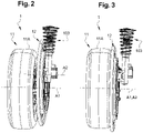
- This device 13 allows said railway wheel 12 to be driven between the passive position illustrated in figure 1 and 2 , and the active position shown in picture 3 .
- the railway wheel 12 in the passive position the railway wheel 12 is decoupled in rotation from the road wheel 11 and the second axis of rotation A2 is eccentric with respect to the first axis of rotation A1, whereas in the active position the railway wheel 12 is coupled in rotation to the road wheel 11 and the second axis of rotation A2 is coaxial with the first axis of rotation A1.
- the rail-road rolling member 1 of the figure 1 devoid of the fixing yoke 104, of the transmission shaft 101 and of the road wheel 11, this in order to better represent the device 13 for supporting and driving said railway wheel 12.
- the hub 102 of the vehicle is secured in a fixed manner to the suspension 103 of the axle via a first fixing lug 102A.
- a second fixing lug 102B of the hub 102 makes it possible to secure it to the fixing yoke 104.
- the device 13 for supporting and driving said railway wheel 12 comprises a guide mechanism 14 for the railway wheel 12 between its active and passive positions, where the guide mechanism 14 is controlled by an electric motor 15.
- the guide mechanism 14 further comprises a support 140, here a support plate 140 forming a handle, provided to be integral in a fixed manner with the hub 102 and comprising two branches 140A, 140B, one branch 140B of which is extended by a extension 140B1 to be connected to a side fixing lug 102C, called the third lug 102C, of the hub 102.
- a support 140 here a support plate 140 forming a handle, provided to be integral in a fixed manner with the hub 102 and comprising two branches 140A, 140B, one branch 140B of which is extended by a extension 140B1 to be connected to a side fixing lug 102C, called the third lug 102C, of the hub 102.
- the guide mechanism 14 comprises a rotating shaft 141 fixed free in rotation on the support 140 around a third axis of rotation A3.
- the fixing of the rotating shaft 141 to the support 140 is carried out by means of bearings 141A, here two bearings 141A, guiding the rotating shaft 141 in rotation around the third axis of rotation A3.
- the third axis of rotation A3 is perpendicular to the first and second axes of rotation A1, A2.
- the rotating shaft 141 comprises at its ends guide arms 16 of the railway wheel 12, in this case two guide arms 16.
- Said extension 140B1 of the arm of the support 140 comprises another bearing 141A on which is mounted free in rotation, around a fourth axis of rotation A4, an auxiliary guide arm 16 .
- the free end of this auxiliary guide arm 16 is secured both to a fixing bracket 12A for the railway wheel 12, and to a connecting rod 17 fixed to the end of one of the other arms of guide 16 connected to the rotating shaft 141.
- the fourth axis of rotation A4 is parallel to the third axis of rotation A3.
- the fixing brackets 12A and the guide arms 16 form attachment points of the railway wheel 12 to the guide mechanism 14.
- the use of three attachment points allows a stable hold of the railway wheel 12, as well as the maintaining its parallelism with respect to the road wheel 11.
- the guide arms 16 form a lever with respect to the rotating shaft 141 making it possible to bring the railway wheel 12 alternately to the passive position or to the active position.
- the rotating shaft 141 is driven using a motion conversion mechanism 18 provided to convert a rotational movement perpendicular to the third axis of rotation A3 into a rotational movement of the rotating shaft 141 around said third axis A3 .
- bevel gears 18A, 18B, also called concurrent, are provided, the output bevel gear 18B of which is coupled in rotation to the rotating shaft 141.
- the input bevel gear 18a is rotationally coupled by its input shaft 18A1 to an electric motor 15.
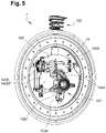
- the railway wheel 12 includes an inner crown 121 and an outer crown 122.
- the inner crown 121 is integral with the device 13 for supporting and driving said railway wheel 12. More particularly, the inner crown 121 is connected to said device 13 via the fixing brackets 12A integral with the inner crown 121 and comprising at their end rings 12A1 on which are mounted free in rotation pins 16A of the guide arms 16 disposed at their end.
- the outer crown 122 ensures the coupling of the railway wheel 12 to the road wheel 11. Furthermore, the outer crown 122 is equipped with a bead 122A on its periphery suitable for running on rails.
- the railway wheel 12 has an outer diameter greater than the outer diameter of the road wheel 11.
- the outer ring 122 of the railway wheel 12 extends radially beyond the road wheel 11.
- a rolling mechanism 123 here a set of balls, interposed between the inner ring 121 and the outer ring 122 allows rotational uncoupling of the inner and outer rings 121, 122 relative to each other. other.
- the rolling member 1 In a driving mode on the road, the rolling member 1 is in a configuration illustrated in figure 2 , where the railway wheel 12 is decoupled in rotation from the road wheel 11.
- the position of the rotating shaft 141 is that of the figure 8 , where the guide arms 16 forming a lever separate the railway wheel 12 from the road wheel 11.
- the railway wheel 12 is then raised relative to the road wheel 11, and the vehicle can move forward on the road.
- the vehicle In a mode of driving on rails, the vehicle is of course previously positioned in correspondence of the rails to allow the engagement of the vehicle on the latter, a platform can be provided for this purpose to raise the vehicle thus allowing the deployment of the railway wheels 12 in active position.
- the electric motor 15 is activated then driving the rotation of the input shaft 18A1 of the motion conversion mechanism 18.
- the input gear 18A whose teeth are engaged with the teeth of the output gear 18B therefore drives the output gear 18B in rotation.
- the rotation of the output gear 18B rotates the rotating shaft 141.
- the rotating shaft 141 then causes the rotational movement of the two guide arms 16 integral with the rotating shaft 141, as well as the rotational movement of the third guide arm 16 actuated by the two guide arms 16 linked to the rotating shaft 141 via the connecting rod 17.
- the guide arms 16 then cause the movement of the railway wheel 12 from its passive position to its active position corresponding to a rotation of the rotating shaft 141 through an angle equal to 160°.
- the orientation of the guide arms 16 in the active position corresponds to the configuration illustrated in figure 9 , and where the outer crown 122 of the railway wheel 12 is pressed against a tire 11A of the road wheel 11 to ensure the coupling of the railway wheel 12 to the road wheel 11.
- the guide arms 16 then keep the outer crown 122 pressed against the tire 11A to ensure this coupling in continuous rotation.
- flange 122A of railway wheel 12 of rolling member 1 is then engaged on the rails, while road wheel 11 is seated on the roadway comprising the rails.
- the seat of the vehicle is ensured by the road wheels 11 only, the railway wheels 12 engaged on the rails having the function of guiding the vehicle on them.
- the road wheels 11 of the vehicle then cause the vehicle to move forward on the roadway comprising the rails.
- the outer crown 122 of the railway wheel 12 is then driven in rotation by the kinetic energy of the road wheel 11.
- the balls of the rolling mechanism 123 allow the rotational decoupling of the outer crown 122 with respect to the inner crown 121 so that only the outer crown 122 is driven in rotation by the road wheel 11.
- the outer crown 122 then guides the vehicle on the rails.
- the electric motor 15 is driven in rotation in the opposite direction to disengage the railway wheels 12 from the rails and bring them into the passive position illustrated in picture 2 .
- the platform provided for engaging the vehicle on the rails also makes it possible to raise the vehicle and then ensure the disengagement bringing the railway wheels 12 into the passive position.
Landscapes
- Engineering & Computer Science (AREA)
- Mechanical Engineering (AREA)
- Transportation (AREA)
- Platform Screen Doors And Railroad Systems (AREA)
- Arrangement And Driving Of Transmission Devices (AREA)
Applications Claiming Priority (1)
| Application Number | Priority Date | Filing Date | Title |
|---|---|---|---|
| FR2011881A FR3116233A1 (fr) | 2020-11-19 | 2020-11-19 | Organe de roulement rail-route amélioré |
Publications (1)
| Publication Number | Publication Date |
|---|---|
| EP4000968A1 true EP4000968A1 (de) | 2022-05-25 |
Family
ID=74553980
Family Applications (1)
| Application Number | Title | Priority Date | Filing Date |
|---|---|---|---|
| EP21209372.8A Pending EP4000968A1 (de) | 2020-11-19 | 2021-11-19 | Verbessertes rollorgan für schiene und strasse |
Country Status (2)
| Country | Link |
|---|---|
| EP (1) | EP4000968A1 (de) |
| FR (1) | FR3116233A1 (de) |
Citations (4)
| Publication number | Priority date | Publication date | Assignee | Title |
|---|---|---|---|---|
| BE379301A (fr) * | 1928-09-01 | 1931-05-30 | Karrier Motors Limited | Perfectionnements apportés aux moyens de transport sur route et rails |
| FR1171550A (fr) * | 1957-01-25 | 1959-01-27 | Chesapeake & Ohio Railway | Perfectionnements aux véhicules pouvant rouler sur route et sur rails |
| NL2000331C2 (nl) * | 2006-11-23 | 2008-05-26 | Movares Nederland Bv | Combiwiel voor een bi-modaal voertuig. |
| FR3043947A1 (fr) * | 2015-11-19 | 2017-05-26 | Soc Des Anciens Etablissements L Geismar | Vehicule mobile sur le sol et sur une voie ferree |
-
2020
- 2020-11-19 FR FR2011881A patent/FR3116233A1/fr active Pending
-
2021
- 2021-11-19 EP EP21209372.8A patent/EP4000968A1/de active Pending
Patent Citations (4)
| Publication number | Priority date | Publication date | Assignee | Title |
|---|---|---|---|---|
| BE379301A (fr) * | 1928-09-01 | 1931-05-30 | Karrier Motors Limited | Perfectionnements apportés aux moyens de transport sur route et rails |
| FR1171550A (fr) * | 1957-01-25 | 1959-01-27 | Chesapeake & Ohio Railway | Perfectionnements aux véhicules pouvant rouler sur route et sur rails |
| NL2000331C2 (nl) * | 2006-11-23 | 2008-05-26 | Movares Nederland Bv | Combiwiel voor een bi-modaal voertuig. |
| FR3043947A1 (fr) * | 2015-11-19 | 2017-05-26 | Soc Des Anciens Etablissements L Geismar | Vehicule mobile sur le sol et sur une voie ferree |
Also Published As
| Publication number | Publication date |
|---|---|
| FR3116233A1 (fr) | 2022-05-20 |
Similar Documents
| Publication | Publication Date | Title |
|---|---|---|
| EP2512855B1 (de) | Motorisierte nabe mit kupplungs- und entkupplungsmitteln | |
| EP2543590B1 (de) | Elektrisches Motorisierungssystem eines Rads | |
| EP0525663B1 (de) | Radmodul mit Motor, insbesondere für Kraftfahrzeuge | |
| EP0414814B1 (de) | Rad eines motorfahrzeuges oder anhängers und ein mit diesem ausgerüstetes fahrzeug | |
| CA2777609C (fr) | Dispositif d'accouplement en rotation d'une couronne a une roue ainsi qu'un atterrisseur d'aeronef muni d'un tel dispositif | |
| EP2883774B1 (de) | Angetriebenes Drehgestell eines Schienenfahrzeugs wobei der Motor im wesentlichen koaxial zur Radsatzwelle angeordnet ist | |
| WO2005032905A1 (fr) | Systeme de guidage pour vehicule le long d’au moins un rail directeur | |
| EP4000968A1 (de) | Verbessertes rollorgan für schiene und strasse | |
| EP0241377A1 (de) | Ausbaubare Antriebseinheit und dazugehöriges Fahrzeug, insbesondere Golfwagen | |
| FR3064590A1 (fr) | Vehicule pendulaire a organes de blocage d'inclinaison | |
| FR2534213A1 (fr) | Tracteur ou vehicule similaire muni de roues motrices et directrices commandees par des fusees | |
| EP1896305A1 (de) | Antriebsmechanismus, insbesondere für eine fensterwischvorrichtung mit einer elliptischen wischbewegung | |
| FR2984243A1 (fr) | Moyeu motorise pour la motorisation electrique d'un essieu d'un vehicule automobile a traction hybride | |
| EP3395640B1 (de) | Drehgestell eines schienenfahrzeugs, das ein bremssystem mit drei bremsscheiben umfasst, die zwischen den achsengehäusen angeordnet sind | |
| EP2127917B1 (de) | Fahrgestell mit elektrischer Federung, das mit einem Reduzierstück ausgestattet ist, und seine Anwendung | |
| EP2066537A1 (de) | Mittel zur führung einer antriebswelle umfassender antriebsmechanismus | |
| FR2896469A1 (fr) | Arbre de direction pour volant a moyeu de direction fixe et mecanisme de moyeu de direction avec arbre de renvoi | |
| WO2010079375A1 (fr) | Dispositif de production de couple, notamment dispositif d'orientation | |
| FR2682647A1 (fr) | Dispositif d'entrainement debrayable pour roues non motrices de vehicule automobile. | |
| FR2689459A1 (fr) | Dispositif d'entrainement des roues non motrices d'un véhicule automobile, par couronne flottante. | |
| EP0112735A1 (de) | Hilfsapparat für Anhängerhandantrieb, insbesondere für Wohnwagen | |
| FR3087514A1 (fr) | Amortisseur compact de couple mecanique | |
| FR2619058A1 (fr) | Dispositif de transmission pour la commande des accessoires d'un moteur a combustion interne de vehicules | |
| CH419217A (fr) | Bogie moteur | |
| BE414270A (de) |
Legal Events
| Date | Code | Title | Description |
|---|---|---|---|
| PUAI | Public reference made under article 153(3) epc to a published international application that has entered the european phase |
Free format text: ORIGINAL CODE: 0009012 |
|
| STAA | Information on the status of an ep patent application or granted ep patent |
Free format text: STATUS: THE APPLICATION HAS BEEN PUBLISHED |
|
| AK | Designated contracting states |
Kind code of ref document: A1 Designated state(s): AL AT BE BG CH CY CZ DE DK EE ES FI FR GB GR HR HU IE IS IT LI LT LU LV MC MK MT NL NO PL PT RO RS SE SI SK SM TR |
|
| STAA | Information on the status of an ep patent application or granted ep patent |
Free format text: STATUS: REQUEST FOR EXAMINATION WAS MADE |
|
| 17P | Request for examination filed |
Effective date: 20220922 |
|
| RAV | Requested validation state of the european patent: fee paid |
Extension state: TN Effective date: 20220922 Extension state: MD Effective date: 20220922 Extension state: MA Effective date: 20220922 Extension state: KH Effective date: 20220922 |
|
| RAX | Requested extension states of the european patent have changed |
Extension state: ME Payment date: 20220922 Extension state: BA Payment date: 20220922 |
|
| RBV | Designated contracting states (corrected) |
Designated state(s): AL AT BE BG CH CY CZ DE DK EE ES FI FR GB GR HR HU IE IS IT LI LT LU LV MC MK MT NL NO PL PT RO RS SE SI SK SM TR |
|
| STAA | Information on the status of an ep patent application or granted ep patent |
Free format text: STATUS: EXAMINATION IS IN PROGRESS |
|
| RAP3 | Party data changed (applicant data changed or rights of an application transferred) |
Owner name: AKKODIS INGENIERIE PRODUIT SAS |
|
| 17Q | First examination report despatched |
Effective date: 20240506 |