EP2543475B1 - Method for grinding thin sheet-like workpiece and double-end surface grinder - Google Patents
Method for grinding thin sheet-like workpiece and double-end surface grinder Download PDFInfo
- Publication number
- EP2543475B1 EP2543475B1 EP12175279.4A EP12175279A EP2543475B1 EP 2543475 B1 EP2543475 B1 EP 2543475B1 EP 12175279 A EP12175279 A EP 12175279A EP 2543475 B1 EP2543475 B1 EP 2543475B1
- Authority
- EP
- European Patent Office
- Prior art keywords
- carrier
- static pressure
- guides
- carrier ring
- workpiece
- Prior art date
- Legal status (The legal status is an assumption and is not a legal conclusion. Google has not performed a legal analysis and makes no representation as to the accuracy of the status listed.)
- Active
Links
- 238000000034 method Methods 0.000 title claims description 37
- 230000003068 static effect Effects 0.000 claims description 283
- 230000002093 peripheral effect Effects 0.000 claims description 41
- 239000012530 fluid Substances 0.000 claims description 23
- 238000005259 measurement Methods 0.000 description 5
- 238000010586 diagram Methods 0.000 description 4
- XUIMIQQOPSSXEZ-UHFFFAOYSA-N Silicon Chemical compound [Si] XUIMIQQOPSSXEZ-UHFFFAOYSA-N 0.000 description 2
- 230000033228 biological regulation Effects 0.000 description 2
- 239000000919 ceramic Substances 0.000 description 2
- 238000004891 communication Methods 0.000 description 2
- 230000000149 penetrating effect Effects 0.000 description 2
- 239000011347 resin Substances 0.000 description 2
- 229920005989 resin Polymers 0.000 description 2
- 229910052710 silicon Inorganic materials 0.000 description 2
- 239000010703 silicon Substances 0.000 description 2
- XLYOFNOQVPJJNP-UHFFFAOYSA-N water Substances O XLYOFNOQVPJJNP-UHFFFAOYSA-N 0.000 description 2
- JOYRKODLDBILNP-UHFFFAOYSA-N Ethyl urethane Chemical compound CCOC(N)=O JOYRKODLDBILNP-UHFFFAOYSA-N 0.000 description 1
- 235000008331 Pinus X rigitaeda Nutrition 0.000 description 1
- 235000011613 Pinus brutia Nutrition 0.000 description 1
- 241000018646 Pinus brutia Species 0.000 description 1
- 238000009825 accumulation Methods 0.000 description 1
- PNEYBMLMFCGWSK-UHFFFAOYSA-N aluminium oxide Inorganic materials [O-2].[O-2].[O-2].[Al+3].[Al+3] PNEYBMLMFCGWSK-UHFFFAOYSA-N 0.000 description 1
- 229910010293 ceramic material Inorganic materials 0.000 description 1
- 239000012050 conventional carrier Substances 0.000 description 1
- 239000013078 crystal Substances 0.000 description 1
- 230000007423 decrease Effects 0.000 description 1
- 230000002950 deficient Effects 0.000 description 1
- 230000006866 deterioration Effects 0.000 description 1
- 230000000694 effects Effects 0.000 description 1
- 238000003754 machining Methods 0.000 description 1
- 238000012423 maintenance Methods 0.000 description 1
- 239000000463 material Substances 0.000 description 1
- 239000002184 metal Substances 0.000 description 1
- 229910001220 stainless steel Inorganic materials 0.000 description 1
- 239000010935 stainless steel Substances 0.000 description 1
Images


Classifications
-
- B—PERFORMING OPERATIONS; TRANSPORTING
- B24—GRINDING; POLISHING
- B24B—MACHINES, DEVICES, OR PROCESSES FOR GRINDING OR POLISHING; DRESSING OR CONDITIONING OF ABRADING SURFACES; FEEDING OF GRINDING, POLISHING, OR LAPPING AGENTS
- B24B7/00—Machines or devices designed for grinding plane surfaces on work, including polishing plane glass surfaces; Accessories therefor
- B24B7/04—Machines or devices designed for grinding plane surfaces on work, including polishing plane glass surfaces; Accessories therefor involving a rotary work-table
-
- B—PERFORMING OPERATIONS; TRANSPORTING
- B24—GRINDING; POLISHING
- B24B—MACHINES, DEVICES, OR PROCESSES FOR GRINDING OR POLISHING; DRESSING OR CONDITIONING OF ABRADING SURFACES; FEEDING OF GRINDING, POLISHING, OR LAPPING AGENTS
- B24B7/00—Machines or devices designed for grinding plane surfaces on work, including polishing plane glass surfaces; Accessories therefor
- B24B7/10—Single-purpose machines or devices
- B24B7/16—Single-purpose machines or devices for grinding end-faces, e.g. of gauges, rollers, nuts, piston rings
- B24B7/17—Single-purpose machines or devices for grinding end-faces, e.g. of gauges, rollers, nuts, piston rings for simultaneously grinding opposite and parallel end faces, e.g. double disc grinders
-
- B—PERFORMING OPERATIONS; TRANSPORTING
- B24—GRINDING; POLISHING
- B24B—MACHINES, DEVICES, OR PROCESSES FOR GRINDING OR POLISHING; DRESSING OR CONDITIONING OF ABRADING SURFACES; FEEDING OF GRINDING, POLISHING, OR LAPPING AGENTS
- B24B37/00—Lapping machines or devices; Accessories
- B24B37/04—Lapping machines or devices; Accessories designed for working plane surfaces
- B24B37/07—Lapping machines or devices; Accessories designed for working plane surfaces characterised by the movement of the work or lapping tool
- B24B37/08—Lapping machines or devices; Accessories designed for working plane surfaces characterised by the movement of the work or lapping tool for double side lapping
-
- B—PERFORMING OPERATIONS; TRANSPORTING
- B24—GRINDING; POLISHING
- B24B—MACHINES, DEVICES, OR PROCESSES FOR GRINDING OR POLISHING; DRESSING OR CONDITIONING OF ABRADING SURFACES; FEEDING OF GRINDING, POLISHING, OR LAPPING AGENTS
- B24B7/00—Machines or devices designed for grinding plane surfaces on work, including polishing plane glass surfaces; Accessories therefor
- B24B7/20—Machines or devices designed for grinding plane surfaces on work, including polishing plane glass surfaces; Accessories therefor characterised by a special design with respect to properties of the material of non-metallic articles to be ground
- B24B7/22—Machines or devices designed for grinding plane surfaces on work, including polishing plane glass surfaces; Accessories therefor characterised by a special design with respect to properties of the material of non-metallic articles to be ground for grinding inorganic material, e.g. stone, ceramics, porcelain
- B24B7/228—Machines or devices designed for grinding plane surfaces on work, including polishing plane glass surfaces; Accessories therefor characterised by a special design with respect to properties of the material of non-metallic articles to be ground for grinding inorganic material, e.g. stone, ceramics, porcelain for grinding thin, brittle parts, e.g. semiconductors, wafers
Definitions
- the present invention relates to a method for grinding a thin sheet-like workpiece and a double-end surface grinder that are used when grinding a thin sheet-like workpiece such as a silicon wafer.
- a direct-contact support method for supporting the workpiece by direct contact with the outer periphery of the workpiece and a carrier support method (Patent Document 3) for supporting the workpiece via a carrier and a carrier ring
- the direct-contact support method includes a roller support method (Patent Document 1) and a belt support method (Patent Document 2).
- roller support method the outer periphery of a disk-shaped workpiece is supported rotatably by a plurality of support rollers in the circumferential direction, and a workpiece is rotated around its center by any of the support rollers.
- belt support method Patent Document 2
- the outer periphery of a disk-shaped workpiece is supported rotatably by two support belts in the circumferential direction, and the workpiece is rotated around its center by the support belts.
- Patent Document 3 a workpiece is fitted into a fitting hole of a thin sheet-like carrier the outer periphery of which is fixed to a carrier ring, the carrier ring is supported by contact with a plurality of support rollers disposed at substantially even intervals at the outer periphery of the carrier ring, and by a drive gear that meshes with a ring gear on the inner peripheral side of the carrier ring, the workpiece is rotated around its center via the carrier ring and the carrier.
- a double-disc grinding apparatus having at least: a rotatable ring-shaped holder for supporting a sheet-like wafer having a notch for indicating a crystal orientation from an outer circumference side along a radial direction, the holder having a protruding portion to be engaged with the crystal-orientation-indicating notch; and a pair of grindstones for simultaneously grinding both surfaces of the wafer supported by the holder, wherein the holder is provided with at least one protruding portion separately from the protruding portion to be engaged with the crystal-orientation-indicating notch, and the both surfaces of the wafer are simultaneously ground by the pair of the grindstones while the wafer is supported and rotated with the at least one protruding portion being engaged with a wafer-supporting notch formed on the wafer.
- the outer periphery of the workpiece is directly supported by support rollers or support belts, and the workpiece is driven and rotated by the support rollers or support belts, so that this method cannot be adopted when grinding a thin sheet-like workpiece with high precision.
- the carrier support method a thin sheet-like carrier the outer periphery of which is fixed to a carrier ring is used, and in a state where a workpiece is fitted in a fitting hole of the carrier, the carrier ring supported by support rollers on the outer periphery is driven and rotated, so that a thin workpiece can be ground with high precision as compared with the direct-contact support method.
- the conventional carrier support method adopts a contact support method in which the carrier ring is supported by contact with a plurality of support rollers disposed at substantially even intervals on the outer periphery of the carrier ring, so that the following problem occurs.
- a guide ring is sandwiched and supported by contact with a plurality of support rollers, so that runouts of the support rollers are transmitted to the carrier ring and synthesized, and due to this combination, the rotation precision of the workpiece is deteriorated. If the attachment precision of the pivots of the support rollers, especially parallelism to the rotation center of the carrier ring is defective, such a problem occurs that a force other than rotation is transmitted to the carrier ring and the carrier ring and the workpiece tilt.
- support rollers As the support rollers, support rollers that were cast molded by using a resin material such as high-hardness urethane and finished by machining so that they hardly damage the carrier ring and reliably support the carrier ring without slippage, may be used, however, in this case, the support rollers are made of resin, so that the following problem occurs. That is, it is difficult to stably obtain circularity required for the support rollers, the quality of the support rollers is easily deteriorated with elapse of time, and further, the support rollers are easily worn.
- the present invention was made in view of these conventional problems, and an object thereof is to provide a method for grinding a thin sheet-like workpiece and a double-end surface grinder that can reduce influences of external forces on a carrier ring and improve workpiece grinding precision, and can maintain high grinding precision over a long period of time without causing problems such as friction.
- a method for grinding a thin sheet-like workpiece in a state where a thin sheet-like workpiece fitted to a carrier is supported by static pressures of a pair of static pressure pads in a non-contact manner, when grinding both surfaces of the workpiece by a pair of grinding wheels while rotating the workpiece via the carrier, an outer peripheral surface of a carrier ring disposed on the outer periphery of the carrier and substantially concentrically with the rotation center of the carrier is supported by static pressures of a plurality of static pressure carrier guides in the circumferential direction in a non-contact manner.
- a double-end surface grinder grinds both surfaces of a thin sheet-like workpiece fitted to a carrier by a pair of grinding wheels while rotating the workpiece via the carrier in a state where the workpiece is supported by static pressures of a pair of static pressure pads in a non-contact manner
- the double-end surface grinder includes, in the circumferential direction, a plurality of static pressure carrier guides that support an outer peripheral surface of a carrier ring disposed on the outer periphery of the carrier and substantially concentrically with the rotation center of the carrier by static pressures in a non-contact manner.
- the carrier ring may have a cylindrical outer peripheral surface, and the static pressure carrier guides may be disposed at substantially even intervals in proximity to the outer peripheral surface.
- the static pressure carrier guides may be fixed.
- the static pressure carrier guide may be floatable.
- Each of the static pressure carrier guides is pivotally supported by a floating shaft substantially parallel to the rotation center of the carrier ring, and each static pressure carrier guide may be provided with a static pressure pocket that supplies a static pressure fluid to the portion between the static pressure carrier guide and the outer peripheral surface of the carrier ring substantially symmetrically about the floating shaft in the rotation direction of the carrier ring.
- the double-end surface grinder may include a support arm that is pivotally supported swingably by a pivot substantially parallel to the rotation center of the carrier ring and supports at least a part of the static pressure carrier guides movably in the directions approaching and separating from the carrier ring, a drive means that turns the support arm around the pivot, and a stopper means that stops the support arm at a predetermined position.
- the static pressure carrier guides may be changeable between a fixed state and a floating state where the static pressure carrier guides float around the floating shafts substantially parallel to the rotation center of the carrier ring.
- the double-end surface grinder may include the static pressure carrier guides that are three or more in number and disposed at substantially even intervals at the outer periphery of the carrier ring, and a space adjusting means that adjusts spaces between the static pressure surfaces of the three or more static pressure carrier guides and the outer peripheral surface of the carrier ring by adjusting the position of at least one of the three or more static pressure carrier guides in the substantially diametrical direction of the carrier ring.
- a carrier ring is supported by static pressures of static pressure carrier guides, so that influences of external forces to be applied to the carrier ring can be reduced, the workpiece grinding precision can be improved, and high grinding precision can be maintained over a long period of time without causing problems such as friction.
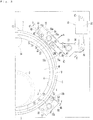
- FIG. 1 and Fig. 2 illustrate a horizontal double-end surface grinder adopting the present invention.
- This horizontal double-end surface grinder includes, as shown in Fig. 1 and Fig. 2 , a pair of left and right static pressure pads 1 that are disposed on the left and right so as to face each other and support a thin sheet-like workpiece W by static pressures in a non-contact manner, a pair of left and right grinding wheels 3 that are disposed rotatably around wheel shafts in the left-right direction corresponding to notched portions 2 of the static pressure pads 1 and move in the central axis direction of a cutting axis to grind both left and right side surfaces of the workpiece W supported by the static pressure pads 1, a carrier 4 that rotates the workpiece W fitted thereto around the center of the cutting axis in a state where the workpiece W is held by the static pressure pads 1, a carrier ring 5 that supports the outer periphery of the carrier 4, and a plurality of static pressure carrier guides
- the static pressure pads 1 are disposed on facing end sides of a pair of left and right movable bases 8 movable in the central axis direction of the cutting axis, and movable in the cutting axis direction between advanced positions at which the static pressure pads hold the workpiece W and withdrawn positions at which the static pressure pads withdraw from the workpiece W, and at the advanced positions, the static pressure pads support the workpiece W by static pressures in a non-contact manner via a static pressure fluid such as static pressure water supplied to the static pressure surface sides facing the workpiece W.
- a static pressure fluid such as static pressure water supplied to the static pressure surface sides facing the workpiece W.
- the carrier 4 is a thin sheet-like disk thinner than the finished thickness of the workpiece W, and has, substantially concentrically, a fitting hole 9 in which the workpiece W is removably fitted.
- the carrier 4 is supported by the carrier ring 5 disposed on the outer periphery of the carrier substantially concentrically, and a presser ring 10 that is fixed to the inside of the carrier ring 5 and presses the outer periphery of the carrier 4 to the carrier ring 5 side.
- the carrier ring 5 has an outer peripheral surface 12 formed into a cylindrical surface substantially concentrically with the rotation center of the carrier 4, and end faces on both sides in the axial center direction face stepped portions 11 on the outer peripheral side of the static pressure surfaces of the static pressure pads 1 via spaces.
- the carrier 4, the carrier ring 5, and the presser ring 10 constitute a carrier means 7, and when inserting or extracting the workpiece W, the workpiece W is inserted or extracted integrally with the carrier means 7.
- the carrier ring 5 is made of a ceramic material such as alumina that is thin in thickness and is easily increased in circularity, however, it may be made of a metal such as a stainless steel.
- a ring gear 13 is provided, and by a drive gear 14 that meshes with the ring gear 13, the carrier means 7 including the carrier 4 and the carrier ring 5 is driven to rotate.
- the static pressure carrier guides 6a and 6b are fitted to a facing end side facing the carrier 4 of one movable base 8, and three or more carrier guides are disposed at substantially even intervals in the circumferential direction at the outer periphery of the carrier ring 5.
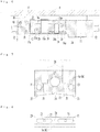
- four static pressure carrier guides 6a and 6b are disposed at substantially evenly-spaced four positions, and as shown in Fig. 3 , Fig. 4 , and Fig. 6 , the static pressure carrier guides 6a and 6b are pivotally attached to the movable base 8 via floating shafts 15a and 15b, and fitted via fixing means 16a and 16b and restricting means 17a and 17b changeably between a fixed state and a floating state.
- a shaft hole 20 through which the floating shaft 15a or 15b is inserted is formed at substantially the center in the rotation direction of the carrier ring 5 (hereinafter, referred to as rotation direction, simply), and two pin holes 21 disposed on both sides of the shaft hole 20, a static pressure surface 22 facing the outer peripheral surface 12 of the carrier ring 5 via a small space, two static pressure pockets 23 provided on the static pressure surface 22 side, and a release groove 24 disposed between the two static pressure pockets 23 are provided.
- the floating shafts 15a and 15b, the pin holes 21, the shaft holes 20 are substantially parallel to the rotation center axis of the carrier ring 5 and the cutting axis, and the pin holes 21 are disposed substantially symmetrically about the shaft hole 20 on both sides in the rotation direction.
- the static pressure surface 22 of each of the static pressure carrier guides 6a and 6b is formed into arc shapes along the outer peripheral surface 12 of the carrier ring 5, and face the outer peripheral surface 12 of the carrier ring 5 via a small space (for example, approximately 10 to 30 micrometers) in the diametrical direction.
- the static pressure pockets 23 are for supplying a static pressure fluid such as static pressure water to the portions between the static pressure surfaces 22 of the static pressure carrier guides 6a and 6b and the outer peripheral surface 12 of the carrier ring 5, and are formed by recesses recessed from the static pressure surfaces 22 and long in the rotation direction, and disposed substantially symmetrically on both sides in the rotation direction with respect to the floating shafts 15a and 15b and the shaft holes 20.
- Each static pressure pocket 23 is connected to a static pressure fluid supply source 29 via a flexible hose 26, etc., on the side opposite to the static pressure surface 22 from a communication hole 25 formed inside.
- static pressure carrier guides 6a and 6b two static pressure carrier guides 6a and 6b facing each other in the diametrical direction of the carrier ring 5 are connected to the static pressure fluid supply source 29 via the same circuit 27 as shown in Fig. 9 .
- a pressure regulation valve 30 and a flow meter 31 are interposed, and they manage the pressure and flow volume.
- the upper side two static pressure carrier guides 6a are fitted to the support arms 34 pivotally attached swingably to the movable base 8 by pivots 33, and when attaching or removing the carrier means 7, the support arms 34 are swung around the pivots 33 by drive means 19 to move the upper side static pressure carrier guides 6a in the directions approaching or separating from the carrier ring 5.
- the pivots 33 are substantially parallel to the floating shafts 15a.
- the static pressure carrier guide 6a On one end side of the support arm 34, the static pressure carrier guide 6a is fitted inside a housing 35, and to the other end side, a cylinder 36 constituting the drive means 19 is joined.
- the housing 35 is provided so as to penetrate in the diametrical direction of the carrier ring 5 between side walls 35a and 35b of the support arm 34, and inside this housing 35, the static pressure carrier guide 6a is housed, and the static pressure carrier guide 6a is pivotally supported by the floating shaft 15a inserted through the support arm 34 by penetrating through the side walls 35a and 35b on both sides of the housing 35.
- the static pressure carrier guide 6a inside the housing 35 is fixable at a proper angle to the support arm 34 by a fixing means 16a as shown in Fig. 3 and Fig. 6 , and becomes floatable within a floating range restricted by the restring means 17a when the fixing means 16 is released.
- the fixing means 16a includes a fixation pin 39 press-fitted in one pine hole 21 of the static pressure carrier guide 6a, and a fixing bracket 38 that has a pin hole 38b which the fixation pin 39 is fitted in and extracted from, and is removably fitted to the side surface of the support arm 34.
- the fixing bracket 38 is removably pivotally attached to the support arm 34 by a fixation bolt 40 on the base portion side, and the angle thereof is adjustable around the fixation bolt 40 by an adjusting bolt 41 that penetrates through a slot 38a of the fixing bracket and is screwed to the support arm 34 side.
- the pin hole 38b is provided on the tip end portion of the fixing bracket38, and in this pinhole 38b, the fixation pin 39 removably fits.
- the restricting means 17a is constituted by the other pin hole 21 of the static pressure carrier guide 6a and a restricting pin 42 penetrating through the housing 35 and inserted through the pin hole 21, and a space corresponding to the floating range is provided between the restricting pin 42 and the pin hole 21.
- a cylinder 36 is interposed between a joint pin 44 of the support arm 34 and the pivot pin 45 of the movable base 8, and swings the support arm 34 around the pivot 33 to move the static pressure carrier guide 6a in the directions approaching or separating from the carrier ring 5 (substantially the diametrical direction) .
- a stopper means 47 On one end side of the support arm 34, a stopper means 47 that stops the support arm 34 at a predetermined position is provided.
- the stopper means 47 includes, as shown in Fig. 3 and Fig. 6 , a contact portion 48 fixed to the movable base 8, and a screw-type stopper 49 screwed adjustably to one end side of the support arm 34, and by adjusting the stopper 49, the distance between the static pressure surfaces 22 of the static pressure carrier guides 6a and 6b on both sides in the diametrical direction of the carrier ring 5 changes and the space can be adjusted so that the carrier ring 5 is positioned at substantially the center between the static pressure carrier guides 6a and 6b. Therefore, the stopper means 47 also serves as a space adjusting means that adjusts the space between the static pressure surface 22 of the static pressure carrier guide 6a and the outer peripheral surface 12 of the carrier ring 5.
- the lower side two static pressure carrier guides 6b are fitted via the floating shafts 15b, the fixing means 16b including fixing brackets 50 (refer to Fig. 3 , Fig. 5 , and Fig. 10 ), and the restricting means 17b (refer to Fig. 11 ) changeably between a fixed state and a floating state.
- the floating shaft 15b is fixed to the movable base 8.
- the fixing bracket 50 is fitted so that one end side in the longitudinal direction thereof is invertible with respect to the floating shaft 15b and the angle of the fixing bracket is adjustable around the floating shaft 15b, and on the other end side, a fixing hole 53 and a floating recess 54 with a diameter larger than that of the fixing hole 53 are provided.
- the static pressure carrier guide 6b is pivotally supported by the floating shaft 15b, and in one pin hole 21, an engagement pin 55 is press-fitted. The amount of projection of the engagement pin 55 to the fixing bracket 50 side is set so that the engagement pin does not engage with the fixing hole 53 when the floating recess 54 is directed toward the static pressure carrier guide 6b side.
- the fixing means 16b for fixing the static pressure carrier guide 6b is constituted by, as shown in Fig. 3 , Fig. 5 , and Fig. 10 , the engagement pin 55 and the pin hole 21 of the fixing bracket 50, and by inserting the engagement pin 55 in the pin hole 21, the static pressure carrier guide 6b is fixed.
- the restricting means 17b that restricts the floating range of the static pressure carrier guide 6b is constituted by, as shown in Fig. 11 , the engagement pin 55 and the floating recess 54 of the fixing bracket 50, and when the engagement pin 55 enters the floating recess 54, the space between these corresponds to the floating range of the static pressure carrier guide 6b.
- a two-split seizing portion 56 that seizes the base portion of the floating shaft 15b, and a fastening bolt 57 that fastens this seizing portion 56 are provided, and the angle of the fixing bracket 50 is adjustable with respect to the floating shaft 15b.
- the fixing hole 53 and the floating recess 54 are formed to be long in the longitudinal direction of the fixing bracket 50 so that the angle of the fixing bracket 50 is adjustable around the floating shaft 15b.
- the workpiece W fitted to the carrier 4 is supported by static pressures of the pair of static pressure pads 1 from both left and right sides in a non-contact manner, and by supplying a static pressure fluid to the outer peripheral surface 12 of the carrier ring 5 from the static pressure pockets 23 of the static pressure carrier guides 6a and 6b disposed at substantially evenly-spaced four positions at the outer periphery of the carrier ring 5, the carrier ring 5 is supported by static pressures of the static pressure carrier guides 6a and 6b via the static pressure fluid in a non-contact manner, and the carrier ring 5 is driven by the drive gear 14 via the ring gear 13 to rotate the workpiece W fitted to the carrier 4 around its rotation center, and accordingly, both surfaces of the workpiece W are ground to a predetermined finished size by the pair of grinding wheels 3.
- the carrier ring 5 can be supported by static pressures of the static pressure carrier guides 6a and 6b at the outer periphery in a non-contact manner.
- the static pressure fluid supplied from the static pressure carrier guides 6a and 6b is present between the static pressure carrier guides and the outer peripheral surface 12 of the carrier ring 5, and by the static pressure carrier guides 6a and 6b, the carrier ring 5 can be supported by static pressures in a non-contact manner from the outer peripheral side via the static pressure fluid.
- the static pressure fluid supplied from the static pressure pads 1 is present between the static pressure carrier guides and the both end faces of the carrier ring 5 as in the conventional case, and by the static pressure pads 1, the carrier ring 5 can be supported by static pressures in a non-contact manner via the static pressure fluid.
- the carrier ring 5 is supported rotatably in a non-contact manner by static pressures of the static pressure carrier guides 6a and 6b via the static pressure fluid, so that problems such as wear, etc., caused by mutual contact between members as in the case of the contact support method do not occur, and high rotation precision can be maintained semipermanently. Therefore, deterioration in grinding precision for the workpiece W, an increase in the number of maintenance works, and occurrence of expenses for consumables due to wear, etc., can be prevented.
- the static pressure carrier guides 6a and 6b disposed at substantially evenly-spaced four positions at the outer periphery of the carrier ring 5 are connected to the same circuit 27 in which the pressure and flow volume of the static pressure fluid are sufficiently high as shown in Fig. 9 , so that when the spaces between the static pressure surfaces 22 of the static pressure carrier guides 6a and 6b and the outer peripheral surface 12 of the carrier ring 5 change, a force acts to equalize the pressure inside the same circuit 27, and the carrier ring 5 tries to maintain its stable position, so that stable rotation precision can be obtained.
- the carrier ring 5 maintains its stable position by moving so that the spaces between the static pressure carrier guides 6a and 6b become equal.
- the outer peripheral surface 12 of the carrier ring 5 is a cylindrical surface substantially concentric with the rotation center of the carrier 4, and is shaped so as not to have a groove, etc., for releasing the pressure of the static pressure fluid, and the static pressure surfaces 22 of the static pressure carrier guides 6a and 6b are in proximity to the outer peripheral surface 12 of the carrier ring 5 via small spaces, so that the carrier ring 5 can be stably supported by the static pressure fluid, and stable rotation precision of the carrier ring 5 can be obtained.
- each of the support arms 34 is swung in the arrow "a" direction shown in Fig. 3 around the pivot 33 by the cylinder 36 as shown by the alternate long and two short dashed line in Fig. 3 so that the upper side two static pressure carrier guides 6a separate in the diametrical direction from the carrier ring 5.
- the support arm 34 is turned in the direction opposite to the arrow "a" direction around the pivot 33 by the cylinder 36.
- the stopper 49 comes into contact with the contact portion 48 and restricts the support arm 34 from turning.
- the spaces between the static pressure surfaces 22 of the static pressure carrier guides 6a and 6b and the outer peripheral surface 12 of the carrier ring 5 can be arbitrarily adjusted. Specifically, by adjusting the stopper 49, the position of the support arm 34 when the stopper 47 comes into contact with the contact portion 48 changes, and the distance between the static pressure surfaces 22 of the static pressure carrier guides 6a and 6b on both sides in the diametrical direction of the carrier ring 5 changes.
- the carrier ring 5 is positioned at substantially the center between the static pressure carrier guides 6a and 6b, and the distances between the outer peripheral surface 12 of the carrier ring 5 and the static pressure surfaces 22 of the static pressure carrier guides 6a and 6b on both sides in the diametrical direction of the carrier ring become substantially equal to each other.
- the distances between the static pressure surfaces 22 of the static pressure carrier guides 6a and 6b and the outer peripheral surface 12 of the carrier ring 5 can be adjusted.
- the static pressure carrier guides 6a and 6b are changeable between a fixed state and a floating state, and by changing the states as appropriate, they can be used appropriately. For example, when the circularity of the carrier ring 5 is high and the carrier ring 5 can be reliably supported by static pressures, the static pressure carrier guides 6a and 6b are fixed, and when the circularity of the carrier ring 5 is low, the static pressure carrier guides 6a and 6b can be floated. It is also possible that the lower side two static pressure carrier guides 6b are fixed and the upper side two static pressure carrier guides 6a are floated.
- Fig. 3 and Fig. 6 show a state where the static pressure carrier guides 6a and 6b are fixed.
- the fixation pin 39 of the static pressure carrier guide 6a is inserted in the pin hole 38b of the fixing bracket 38, and the fixing bracket 38 is pivotally attached to the support arm 34 by the fixation bolt 40.
- An adjustment allowance when fixing the static pressure carrier guide 6a is normally within the range of the space between the pinhole 21 and the restricting pin 42, so that the restricting pin 42 may be left inserted in the pin hole 21.
- the size of the space between the static pressure surface 22 of the static pressure carrier guide 6a and the outer peripheral surface 12 of the carrier ring 5 is appropriately adjusted by the stopper means 47.
- the engagement pin 55 is inserted in the fixing hole 53 for fixing the static pressure carrier guide 6b and the fixing bracket 50, and the angle of the fixing bracket 50 is adjusted by turning around the floating shaft 15b so that the space between the static pressure surface 22 of the static pressure carrier guide 6b and the outer peripheral surface 12 of the carrier ring 5 becomes substantially equal between both sides of the floating shaft 15b, and then the fastening bolt 57 is tightened to fix the fixing bracket 50 to the floating shaft 15b. Accordingly, the lower side static pressure carrier guide 6b is fixed.
- static pressure carrier guides 6a and 6b are fixed, two static pressure pockets 23 are present in the static pressure surfaces 22 of the static pressure carrier guides 6a and 6b, and the static pressure fluid is supplied from these static pressure pockets 23 to the outer peripheral surface 12 of the carrier ring 5, so that the carrier ring 5 can be supported by static pressures via the static pressure fluid.
- the static pressure carrier guides 6a and 6b are in a fixed state, so that the carrier ring 5 can be prevented from wobbling and the carrier ring 5 can be reliably supported by static pressures.
- the fixation pin 39 of the static pressure carrier guide 6a comes off the pin hole 38b of the fixing bracket 38, so that fixation of the static pressure carrier guide 6a by the fixing means 16a can be released. Accordingly, the static pressure carrier guide 6a can be floated around the floating shaft 15a within the range of the space between the restricting pin 42 and the pin hole 21.
- the static pressure carrier guide 6b is fitted in a floatable manner in the range of the restricting means 17b.
- the static pressure carrier guide 6b is removed from the floating shaft 15b, and the fixing bracket 50 is inverted and fitted to the floating shaft 15b.
- the static pressure carrier guide 6b is fitted over the floating shaft 15b, and the engagement pin 55 is engaged with the floating recess 54 of the fixed bracket 50.
- the fixing bracket 50 is adjusted around the floating shaft 15b so that the space between the static pressure surface 22 of the static pressure carrier guide 6b and the outer peripheral surface 12 of the carrier ring 5 becomes substantially equal between both sides of the floating shaft 15b, and the fixing bracket is fixed by a fastening bolt 57. Accordingly, within the range between the engagement pin 55 and the floating recess 54, the static pressure carrier guide 6b can be floated around the floating shaft 15b.
- the carrier ring 5 can be supported by static pressures via the static pressure fluid.
- the static pressure carrier guides 6a and 6b float around the floating shafts 15a and 15b so that the spaces become substantially equal between both sides of the floating shafts 15a and 15b. Therefore, the static pressure carrier guides 6a and 6b can be prevented from coming into contact with the carrier ring 5.
- the restricting means 17a and 17b that restrict floating ranges of the static pressure carrier guides 6a and 6b are provided, so that unstable swing, etc., of the static pressure carrier guides 6a and 6b around the floating shafts 15a and 15b can be prevented.
- the static pressure carrier guide 6a when attaching the upper side static pressure carrier guide 6a to the support arm 34 that turns around the pivot 33, if the static pressure carrier guide 6a is fixed to the support arm 34, the static pressure carrier guide 6a may come into contact with the carrier ring 5 due to accumulation of errors, etc., and it becomes hard to make small the spaces between the static pressure carrier guides 6a and 6b and the carrier ring 5.
- the upper side static pressure carrier guide 6a can be prevented from coming into contact with the carrier ring 5 by floating of the upper side static pressure carrier guide 6a while the spaces between the static pressure surfaces 22 of the static pressure carrier guides 6a and 6b and the outer peripheral surface 12 of the carrier ring 5 are made small.
- the edge runout of the carrier ring 5 could be reduced to approximately 1/5 as compared with the conventional contact support method.
- Fig. 12 shows results of measurement of circularity of the carrier ring 5.
- Fig. 13 and Fig. 14 shows results of measurements of edge runout of the carrier ring 5 in the conventional contact support method and in the non- contact support method according to the present invention, respectively.
- a carrier ring that was made of ceramic and has an outer periphery circularity of 5 micrometers (measured value: 4. 5 micrometers) was used and edge runouts of the carrier ring 5 in the conventional contact support method and in the non-contact support method according to the present invention were measured.
- a measured value of the edge runout is approximately 15 micrometers as shown in Fig. 13 , and from this value, when the outer periphery circularity (approximately 5 micrometers) of the carrier ring 5 is deducted, the edge runout is approximately 10 micrometers.
- the measured value of the runout in the case of the non- contact support method is approximately 7 micrometers as shown in Fig. 14 , and from this, when the outer periphery circularity (approximately 5 micrometers) of the carrier ring 5 is deducted, the edge runout is approximately 2 micrometers.
- the edge runout of the carrier ring 5 can be reduced to approximately 1/5 as compared with the conventional contact support method. Therefore, the rotation precision of the carrier ring 5 is directly transmitted to the workpiece W in contact with the inner periphery of the carrier ring via the carrier 4, and acts on the grinding point of the workpiece W sandwiched and fixed by the pair of grinding wheels 3 in a grinding cycle and immediately influences grinding of the workpiece W, however, by adopting the non-contact support method according to the present invention, the influence of the edge runout of the carrier ring 5 can be reduced, and stable grinding precision for the workpiece W can be obtained.
- the present invention is not limited to the embodiments, and can be variously changed without departing from the spirit of the present invention.
- the static pressure carrier guides 6a and 6b can be changed between a fixed state and a floating state, however, it is also possible that all static pressure carrier guides 6a and 6b are fixed or floated, or the plurality of lower side static pressure carrier guides 6b are fixed and the plurality of upper side static pressure carrier guides 6a are floated.
- the static pressure carrier guides 6a and 6b are preferably disposed at substantially even intervals at the outer periphery of the carrier ring 5, however, they do not need to be disposed at substantially even intervals as long as the carrier ring 5 can be supported by static pressures of the plurality of static pressure carrier guides 6a and 6b.
- the static pressure carrier guides 6a and 6b are disposed at substantially even intervals, the static pressure carrier guides 6a and 6b are three or more in number.
- the number of static pressure carrier guides 6a and 6b is three, for example, two static pressure carrier guides 6b are disposed on the lower side, and the upper side one static pressure carrier guide 6a is provided movably in the diametrical direction of the carrier ring 5.
- the movable base 8 is provided with a guide mechanism in the substantially diametrical direction of the carrier ring 5, and the static pressure carrier guides 6a and 6b may be provided movably along the guide mechanism.
- the stopper means 47 that stops the support arm 34 at a predetermined position is also used as a space adjusting means that adjusts the space between the static pressure surface 22 of the static pressure carrier guide 6a or 6b and the outer peripheral surface 12 of the carrier ring 5, however, these means may be provided separately.
- All of the static pressure carrier guides 6a and 6b may be connected to the static pressure fluid supply source 29 via the same circuit 27, or the static pressure carrier guides 6a and 6b may be individually connected to the supply source 29 via independent pressure control circuits. Further, in the embodiment, a horizontal surface grinder is illustrated, however, the present invention can also be carried out in a vertical surface grinder. As the workpiece W, any workpiece can be used as long as it is a thin sheet-like workpiece.
Description
- The present invention relates to a method for grinding a thin sheet-like workpiece and a double-end surface grinder that are used when grinding a thin sheet-like workpiece such as a silicon wafer.
- When grinding a thin sheet-like workpiece such as a silicon wafer by using a horizontal double-end surface grinder, while rotating the workpiece supported by static pressures of a pair of left and right static pressure pads in a non-contact manner around its center, the workpiece is ground to a predetermined finished thickness by a pair of left and right grinding wheels rotating around a horizontal shaft.
- As a method for supporting the workpiece rotatably, there is a direct-contact support method (
Patent Documents 1 and 2) for supporting the workpiece by direct contact with the outer periphery of the workpiece and a carrier support method (Patent Document 3) for supporting the workpiece via a carrier and a carrier ring, and the direct-contact support method includes a roller support method (Patent Document 1) and a belt support method (Patent Document 2). - In the roller support method (Patent Document 1), the outer periphery of a disk-shaped workpiece is supported rotatably by a plurality of support rollers in the circumferential direction, and a workpiece is rotated around its center by any of the support rollers. In the belt support method (Patent Document 2), the outer periphery of a disk-shaped workpiece is supported rotatably by two support belts in the circumferential direction, and the workpiece is rotated around its center by the support belts.
- In the carrier support method (Patent Document 3), a workpiece is fitted into a fitting hole of a thin sheet-like carrier the outer periphery of which is fixed to a carrier ring, the carrier ring is supported by contact with a plurality of support rollers disposed at substantially even intervals at the outer periphery of the carrier ring, and by a drive gear that meshes with a ring gear on the inner peripheral side of the carrier ring, the workpiece is rotated around its center via the carrier ring and the carrier.
- Moreover, a double-disc grinding apparatus (Patent Document 4) is known having at least: a rotatable ring-shaped holder for supporting a sheet-like wafer having a notch for indicating a crystal orientation from an outer circumference side along a radial direction, the holder having a protruding portion to be engaged with the crystal-orientation-indicating notch; and a pair of grindstones for simultaneously grinding both surfaces of the wafer supported by the holder, wherein the holder is provided with at least one protruding portion separately from the protruding portion to be engaged with the crystal-orientation-indicating notch, and the both surfaces of the wafer are simultaneously ground by the pair of the grindstones while the wafer is supported and rotated with the at least one protruding portion being engaged with a wafer-supporting notch formed on the wafer.
-
- [Patent Document 1] Japanese Published Unexamined Patent Application No.
H10-175144 - [Patent Document 2] Japanese Published Unexamined Patent Application No.
H10-156681 - [Patent Document 3] Japanese Published Unexamined Patent Application No.
2005-205528 - [Patent Document 4]
US 2011/039476 A1 - In the conventional direct-contact support method, the outer periphery of the workpiece is directly supported by support rollers or support belts, and the workpiece is driven and rotated by the support rollers or support belts, so that this method cannot be adopted when grinding a thin sheet-like workpiece with high precision.
- On the other hand, in the carrier support method, a thin sheet-like carrier the outer periphery of which is fixed to a carrier ring is used, and in a state where a workpiece is fitted in a fitting hole of the carrier, the carrier ring supported by support rollers on the outer periphery is driven and rotated, so that a thin workpiece can be ground with high precision as compared with the direct-contact support method. However, the conventional carrier support method adopts a contact support method in which the carrier ring is supported by contact with a plurality of support rollers disposed at substantially even intervals on the outer periphery of the carrier ring, so that the following problem occurs.
- That is, conventionally, a guide ring is sandwiched and supported by contact with a plurality of support rollers, so that runouts of the support rollers are transmitted to the carrier ring and synthesized, and due to this combination, the rotation precision of the workpiece is deteriorated. If the attachment precision of the pivots of the support rollers, especially parallelism to the rotation center of the carrier ring is defective, such a problem occurs that a force other than rotation is transmitted to the carrier ring and the carrier ring and the workpiece tilt.
- As the support rollers, support rollers that were cast molded by using a resin material such as high-hardness urethane and finished by machining so that they hardly damage the carrier ring and reliably support the carrier ring without slippage, may be used, however, in this case, the support rollers are made of resin, so that the following problem occurs. That is, it is difficult to stably obtain circularity required for the support rollers, the quality of the support rollers is easily deteriorated with elapse of time, and further, the support rollers are easily worn.
- The present invention was made in view of these conventional problems, and an object thereof is to provide a method for grinding a thin sheet-like workpiece and a double-end surface grinder that can reduce influences of external forces on a carrier ring and improve workpiece grinding precision, and can maintain high grinding precision over a long period of time without causing problems such as friction.
- In a method for grinding a thin sheet-like workpiece according to the present invention, in a state where a thin sheet-like workpiece fitted to a carrier is supported by static pressures of a pair of static pressure pads in a non-contact manner, when grinding both surfaces of the workpiece by a pair of grinding wheels while rotating the workpiece via the carrier, an outer peripheral surface of a carrier ring disposed on the outer periphery of the carrier and substantially concentrically with the rotation center of the carrier is supported by static pressures of a plurality of static pressure carrier guides in the circumferential direction in a non-contact manner.
- A double-end surface grinder according to the present invention grinds both surfaces of a thin sheet-like workpiece fitted to a carrier by a pair of grinding wheels while rotating the workpiece via the carrier in a state where the workpiece is supported by static pressures of a pair of static pressure pads in a non-contact manner, wherein the double-end surface grinder includes, in the circumferential direction, a plurality of static pressure carrier guides that support an outer peripheral surface of a carrier ring disposed on the outer periphery of the carrier and substantially concentrically with the rotation center of the carrier by static pressures in a non-contact manner.
- The carrier ring may have a cylindrical outer peripheral surface, and the static pressure carrier guides may be disposed at substantially even intervals in proximity to the outer peripheral surface. The static pressure carrier guides may be fixed. Alternatively, the static pressure carrier guide may be floatable.
- Each of the static pressure carrier guides is pivotally supported by a floating shaft substantially parallel to the rotation center of the carrier ring, and each static pressure carrier guide may be provided with a static pressure pocket that supplies a static pressure fluid to the portion between the static pressure carrier guide and the outer peripheral surface of the carrier ring substantially symmetrically about the floating shaft in the rotation direction of the carrier ring.
- The double-end surface grinder may include a support arm that is pivotally supported swingably by a pivot substantially parallel to the rotation center of the carrier ring and supports at least a part of the static pressure carrier guides movably in the directions approaching and separating
from the carrier ring, a drive means that turns the support arm around the pivot, and a stopper means that stops the support arm at a predetermined position. - The static pressure carrier guides may be changeable between a fixed state and a floating state where the static pressure carrier guides float around the floating shafts substantially parallel to the rotation center of the carrier ring.
- The double-end surface grinder may include the static pressure carrier guides that are three or more in number and disposed at substantially even intervals at the outer periphery of the carrier ring, and a space adjusting means that adjusts spaces between the static pressure surfaces of the three or more static pressure carrier guides and the outer peripheral surface of the carrier ring by adjusting the position of at least one of the three or more static pressure carrier guides in the substantially diametrical direction of the carrier ring.
- According to the present invention, a carrier ring is supported by static pressures of static pressure carrier guides, so that influences of external forces to be applied to the carrier ring can be reduced, the workpiece grinding precision can be improved, and high grinding precision can be maintained over a long period of time without causing problems such as friction.
-
- [
Fig. 1 ] is a schematic side view of a horizontal double-end surface grinder showing an embodiment of the present invention. - [
Fig. 2 ] is a schematic sectional view of the same. - [
Fig. 3 ] is an enlarged side view of an essential portion of the same. - [
Fig. 4 ] is an enlarged sectional view of a support portion of an upper side static pressure carrier guide of the same. - [
Fig. 5 ] is a sectional view of a fixed state of the static pressure carrier guide of the same. - [
Fig. 6 ] is a sectional view taken along line X-X inFig. 3 of the same. - [
Fig. 7 ] is a sectional view of the static pressure carrier guide of the same. - [
Fig. 8 ] is a bottom view of the static pressure carrier guide of the same. - [
Fig. 9 ] is a static pressure circuit diagram of the static pressure carrier guides of the same. - [
Fig. 10 ] is a sectional view taken along line Y-Y inFig. 3 of the same. - [
Fig. 11 ] is a sectional view showing a floating state of the static pressure carrier guide of the same. - [
Fig. 12 ] is a diagram showing results of measurement of circularity of the carrier ring. - [
Fig. 13 ] is a diagram showing results of measurement of edge runout of the carrier ring in a conventional contact support method. - [
Fig. 14 ] is a diagram showing results of measurement of edge runout of the carrier ring in a non-contact support method according to the present invention. - Hereinafter, embodiments of the present invention are described in detail with reference to the drawings . The drawings illustrate a horizontal double-end surface grinder adopting the present invention. This horizontal double-end surface grinder includes, as shown in
Fig. 1 and Fig. 2 , a pair of left and rightstatic pressure pads 1 that are disposed on the left and right so as to face each other and support a thin sheet-like workpiece W by static pressures in a non-contact manner, a pair of left and right grindingwheels 3 that are disposed rotatably around wheel shafts in the left-right direction corresponding to notchedportions 2 of thestatic pressure pads 1 and move in the central axis direction of a cutting axis to grind both left and right side surfaces of the workpiece W supported by thestatic pressure pads 1, acarrier 4 that rotates the workpiece W fitted thereto around the center of the cutting axis in a state where the workpiece W is held by thestatic pressure pads 1, acarrier ring 5 that supports the outer periphery of thecarrier 4, and a plurality of static pressure carrier guides 6a and 6b that are disposed at substantially even intervals at the outer periphery of thecarrier ring 5 and support thecarrier ring 5 rotatably by static pressures in a non-contact manner from the outer periphery. - The
static pressure pads 1 are disposed on facing end sides of a pair of left and rightmovable bases 8 movable in the central axis direction of the cutting axis, and movable in the cutting axis direction between advanced positions at which the static pressure pads hold the workpiece W and withdrawn positions at which the static pressure pads withdraw from the workpiece W, and at the advanced positions, the static pressure pads support the workpiece W by static pressures in a non-contact manner via a static pressure fluid such as static pressure water supplied to the static pressure surface sides facing the workpiece W. - The
carrier 4 is a thin sheet-like disk thinner than the finished thickness of the workpiece W, and has, substantially concentrically, afitting hole 9 in which the workpiece W is removably fitted. Thecarrier 4 is supported by thecarrier ring 5 disposed on the outer periphery of the carrier substantially concentrically, and apresser ring 10 that is fixed to the inside of thecarrier ring 5 and presses the outer periphery of thecarrier 4 to thecarrier ring 5 side. Thecarrier ring 5 has an outerperipheral surface 12 formed into a cylindrical surface substantially concentrically with the rotation center of thecarrier 4, and end faces on both sides in the axial center direction face steppedportions 11 on the outer peripheral side of the static pressure surfaces of thestatic pressure pads 1 via spaces. Thecarrier 4, thecarrier ring 5, and thepresser ring 10 constitute a carrier means 7, and when inserting or extracting the workpiece W, the workpiece W is inserted or extracted integrally with the carrier means 7. - The
carrier ring 5 is made of a ceramic material such as alumina that is thin in thickness and is easily increased in circularity, however, it may be made of a metal such as a stainless steel. On the inner periphery of thepresser ring 10, aring gear 13 is provided, and by adrive gear 14 that meshes with thering gear 13, the carrier means 7 including thecarrier 4 and thecarrier ring 5 is driven to rotate. - The static
pressure carrier guides carrier 4 of onemovable base 8, and three or more carrier guides are disposed at substantially even intervals in the circumferential direction at the outer periphery of thecarrier ring 5. For example, in the present embodiment, four static pressure carrier guides 6a and 6b are disposed at substantially evenly-spaced four positions, and as shown inFig. 3 ,Fig. 4 , andFig. 6 , the static pressure carrier guides 6a and 6b are pivotally attached to themovable base 8 via floatingshafts means - In each static
pressure carrier guide Fig. 7 and Fig. 8 , ashaft hole 20 through which the floatingshaft pin holes 21 disposed on both sides of theshaft hole 20, astatic pressure surface 22 facing the outerperipheral surface 12 of thecarrier ring 5 via a small space, two static pressure pockets 23 provided on thestatic pressure surface 22 side, and arelease groove 24 disposed between the two static pressure pockets 23 are provided. The floatingshafts carrier ring 5 and the cutting axis, and the pin holes 21 are disposed substantially symmetrically about theshaft hole 20 on both sides in the rotation direction. - The
static pressure surface 22 of each of the static pressure carrier guides 6a and 6b is formed into arc shapes along the outerperipheral surface 12 of thecarrier ring 5, and face the outerperipheral surface 12 of thecarrier ring 5 via a small space (for example, approximately 10 to 30 micrometers) in the diametrical direction. The static pressure pockets 23 are for supplying a static pressure fluid such as static pressure water to the portions between the static pressure surfaces 22 of the static pressure carrier guides 6a and 6b and the outerperipheral surface 12 of thecarrier ring 5, and are formed by recesses recessed from the static pressure surfaces 22 and long in the rotation direction, and disposed substantially symmetrically on both sides in the rotation direction with respect to the floatingshafts static pressure pocket 23 is connected to a static pressurefluid supply source 29 via aflexible hose 26, etc., on the side opposite to thestatic pressure surface 22 from acommunication hole 25 formed inside. - Among the static pressure carrier guides 6a and 6b, two static pressure carrier guides 6a and 6b facing each other in the diametrical direction of the
carrier ring 5 are connected to the static pressurefluid supply source 29 via thesame circuit 27 as shown inFig. 9 . In eachcircuit 27, apressure regulation valve 30 and aflow meter 31 are interposed, and they manage the pressure and flow volume. - The upper side two static pressure carrier guides 6a are fitted to the
support arms 34 pivotally attached swingably to themovable base 8 bypivots 33, and when attaching or removing the carrier means 7, thesupport arms 34 are swung around thepivots 33 by drive means 19 to move the upper side static pressure carrier guides 6a in the directions approaching or separating from thecarrier ring 5. Thepivots 33 are substantially parallel to the floatingshafts 15a. - On one end side of the
support arm 34, the staticpressure carrier guide 6a is fitted inside ahousing 35, and to the other end side, acylinder 36 constituting the drive means 19 is joined. As shown inFig. 4 andFig. 6 , thehousing 35 is provided so as to penetrate in the diametrical direction of thecarrier ring 5 betweenside walls support arm 34, and inside thishousing 35, the staticpressure carrier guide 6a is housed, and the staticpressure carrier guide 6a is pivotally supported by the floatingshaft 15a inserted through thesupport arm 34 by penetrating through theside walls housing 35. The staticpressure carrier guide 6a inside thehousing 35 is fixable at a proper angle to thesupport arm 34 by a fixing means 16a as shown inFig. 3 andFig. 6 , and becomes floatable within a floating range restricted by the restring means 17a when the fixing means 16 is released. - The fixing means 16a includes a
fixation pin 39 press-fitted in onepine hole 21 of the staticpressure carrier guide 6a, and a fixingbracket 38 that has apin hole 38b which thefixation pin 39 is fitted in and extracted from, and is removably fitted to the side surface of thesupport arm 34. The fixingbracket 38 is removably pivotally attached to thesupport arm 34 by a fixation bolt 40 on the base portion side, and the angle thereof is adjustable around the fixation bolt 40 by an adjusting bolt 41 that penetrates through aslot 38a of the fixing bracket and is screwed to thesupport arm 34 side. Thepin hole 38b is provided on the tip end portion of the fixing bracket38, and in thispinhole 38b, thefixation pin 39 removably fits. The restrictingmeans 17a is constituted by theother pin hole 21 of the staticpressure carrier guide 6a and a restrictingpin 42 penetrating through thehousing 35 and inserted through thepin hole 21, and a space corresponding to the floating range is provided between the restrictingpin 42 and thepin hole 21. - A
cylinder 36 is interposed between ajoint pin 44 of thesupport arm 34 and thepivot pin 45 of themovable base 8, and swings thesupport arm 34 around thepivot 33 to move the staticpressure carrier guide 6a in the directions approaching or separating from the carrier ring 5 (substantially the diametrical direction) . On one end side of thesupport arm 34, a stopper means 47 that stops thesupport arm 34 at a predetermined position is provided. - The stopper means 47 includes, as shown in
Fig. 3 andFig. 6 , acontact portion 48 fixed to themovable base 8, and a screw-type stopper 49 screwed adjustably to one end side of thesupport arm 34, and by adjusting thestopper 49, the distance between the static pressure surfaces 22 of the static pressure carrier guides 6a and 6b on both sides in the diametrical direction of thecarrier ring 5 changes and the space can be adjusted so that thecarrier ring 5 is positioned at substantially the center between the static pressure carrier guides 6a and 6b. Therefore, the stopper means 47 also serves as a space adjusting means that adjusts the space between thestatic pressure surface 22 of the staticpressure carrier guide 6a and the outerperipheral surface 12 of thecarrier ring 5. - As shown in
Fig. 3 ,Fig. 5 ,Fig. 10, and Fig. 11 , the lower side two static pressure carrier guides 6b are fitted via the floatingshafts 15b, the fixing means 16b including fixing brackets 50 (refer toFig. 3 ,Fig. 5 , andFig. 10 ), and the restrictingmeans 17b (refer toFig. 11 ) changeably between a fixed state and a floating state. - The floating
shaft 15b is fixed to themovable base 8. The fixingbracket 50 is fitted so that one end side in the longitudinal direction thereof is invertible with respect to the floatingshaft 15b and the angle of the fixing bracket is adjustable around the floatingshaft 15b, and on the other end side, a fixinghole 53 and a floatingrecess 54 with a diameter larger than that of the fixinghole 53 are provided. The staticpressure carrier guide 6b is pivotally supported by the floatingshaft 15b, and in onepin hole 21, anengagement pin 55 is press-fitted. The amount of projection of theengagement pin 55 to the fixingbracket 50 side is set so that the engagement pin does not engage with the fixinghole 53 when the floatingrecess 54 is directed toward the staticpressure carrier guide 6b side. - The fixing means 16b for fixing the static
pressure carrier guide 6b is constituted by, as shown inFig. 3 ,Fig. 5 , andFig. 10 , theengagement pin 55 and thepin hole 21 of the fixingbracket 50, and by inserting theengagement pin 55 in thepin hole 21, the staticpressure carrier guide 6b is fixed. - The restricting means 17b that restricts the floating range of the static
pressure carrier guide 6b is constituted by, as shown inFig. 11 , theengagement pin 55 and the floatingrecess 54 of the fixingbracket 50, and when theengagement pin 55 enters the floatingrecess 54, the space between these corresponds to the floating range of the staticpressure carrier guide 6b. - On one end side of the fixing
bracket 50, a two-split seizing portion 56 that seizes the base portion of the floatingshaft 15b, and afastening bolt 57 that fastens this seizingportion 56 are provided, and the angle of the fixingbracket 50 is adjustable with respect to the floatingshaft 15b. The fixinghole 53 and the floatingrecess 54 are formed to be long in the longitudinal direction of the fixingbracket 50 so that the angle of the fixingbracket 50 is adjustable around the floatingshaft 15b. - When grinding a workpiece W, the workpiece W fitted to the
carrier 4 is supported by static pressures of the pair ofstatic pressure pads 1 from both left and right sides in a non-contact manner, and by supplying a static pressure fluid to the outerperipheral surface 12 of thecarrier ring 5 from the static pressure pockets 23 of the static pressure carrier guides 6a and 6b disposed at substantially evenly-spaced four positions at the outer periphery of thecarrier ring 5, thecarrier ring 5 is supported by static pressures of the static pressure carrier guides 6a and 6b via the static pressure fluid in a non-contact manner, and thecarrier ring 5 is driven by thedrive gear 14 via thering gear 13 to rotate the workpiece W fitted to thecarrier 4 around its rotation center, and accordingly, both surfaces of the workpiece W are ground to a predetermined finished size by the pair of grindingwheels 3. - Accordingly, the
carrier ring 5 can be supported by static pressures of the static pressure carrier guides 6a and 6b at the outer periphery in a non-contact manner. Specifically, the static pressure fluid supplied from the static pressure carrier guides 6a and 6b is present between the static pressure carrier guides and the outerperipheral surface 12 of thecarrier ring 5, and by the static pressure carrier guides 6a and 6b, thecarrier ring 5 can be supported by static pressures in a non-contact manner from the outer peripheral side via the static pressure fluid. On the other hand, the static pressure fluid supplied from thestatic pressure pads 1 is present between the static pressure carrier guides and the both end faces of thecarrier ring 5 as in the conventional case, and by thestatic pressure pads 1, thecarrier ring 5 can be supported by static pressures in a non-contact manner via the static pressure fluid. - Therefore, all of the outer periphery and both end faces of the
carrier ring 5 are supported by static pressures in a non-contact manner, and in comparison with the conventional contact support method in which thecarrier ring 5 is supported by guide rollers, external forces to be applied to the workpiece W from thecarrier ring 5 via thecarrier 4 during a grinding cycle are reduced, so that the rotation precision (mainly, edge runout) of the workpiece W can be improved. Therefore, the grinding precision for the workpiece W can be improved. - In addition, the
carrier ring 5 is supported rotatably in a non-contact manner by static pressures of the static pressure carrier guides 6a and 6b via the static pressure fluid, so that problems such as wear, etc., caused by mutual contact between members as in the case of the contact support method do not occur, and high rotation precision can be maintained semipermanently. Therefore, deterioration in grinding precision for the workpiece W, an increase in the number of maintenance works, and occurrence of expenses for consumables due to wear, etc., can be prevented. - Among the static pressure carrier guides 6a and 6b disposed at substantially evenly-spaced four positions at the outer periphery of the
carrier ring 5, the static pressure carrier guides 6a and 6b disposed so as to face each other in the diametrical direction of thecarrier ring 5 are connected to thesame circuit 27 in which the pressure and flow volume of the static pressure fluid are sufficiently high as shown inFig. 9 , so that when the spaces between the static pressure surfaces 22 of the static pressure carrier guides 6a and 6b and the outerperipheral surface 12 of thecarrier ring 5 change, a force acts to equalize the pressure inside thesame circuit 27, and thecarrier ring 5 tries to maintain its stable position, so that stable rotation precision can be obtained. - Specifically, if the pressure balance between the pair of static pressure carrier guides 6a and 6b facing each other is lost for some reason and, for example, the space between the lower side static
pressure carrier guide 6b and thecarrier ring 5 becomes narrower, the pressure inside the static pressure pockets 23 of this staticpressure carrier guide 6b increases. On the other hand, the space between the upper side staticpressure carrier guide 6a and thecarrier ring 5 becomes larger, and the pressure inside the static pressure pockets 23 of this static pressure carrier guide 6a decreases. Therefore, according to the pressure difference between the static pressure pockets 23 of the static pressure carrier guides 6a and 6b, thecarrier ring 5 maintains its stable position by moving so that the spaces between the static pressure carrier guides 6a and 6b become equal. - The outer
peripheral surface 12 of thecarrier ring 5 is a cylindrical surface substantially concentric with the rotation center of thecarrier 4, and is shaped so as not to have a groove, etc., for releasing the pressure of the static pressure fluid, and the static pressure surfaces 22 of the static pressure carrier guides 6a and 6b are in proximity to the outerperipheral surface 12 of thecarrier ring 5 via small spaces, so that thecarrier ring 5 can be stably supported by the static pressure fluid, and stable rotation precision of thecarrier ring 5 can be obtained. In addition, on thestatic pressure surface 22 of each of the static pressure carrier guides 6a and 6b, two static pressure pockets 23 are provided in the rotation direction of thecarrier ring 5, and are divided into two by therelease groove 24 between the two static pressure pockets, so that the pressures of the static pressure fluid on both sides in the rotation direction of thecarrier ring 5 can be balanced by each staticpressure carrier guide - When attaching or removing the carrier means 7, each of the
support arms 34 is swung in the arrow "a" direction shown inFig. 3 around thepivot 33 by thecylinder 36 as shown by the alternate long and two short dashed line inFig. 3 so that the upper side two static pressure carrier guides 6a separate in the diametrical direction from thecarrier ring 5. After thecarrier ring 5 is inserted into the predetermined position, thesupport arm 34 is turned in the direction opposite to the arrow "a" direction around thepivot 33 by thecylinder 36. When the space between thestatic pressure surface 22 of the upper side staticpressure carrier guide 6a and the outerperipheral surface 12 of thecarrier ring 5 becomes the predetermined space, thestopper 49 comes into contact with thecontact portion 48 and restricts thesupport arm 34 from turning. - Thus, by moving the upper side static
pressure carrier guide 6a by driving thesupport arm 34 by thecylinder 36, the distance between the pair of static pressure carrier guides 6a and 6b disposed so as to face each other in the diametrical direction of thecarrier ring 5 is changed, so that thecarrier ring 5 can be easily inserted and extracted, and this operation can be easily automatized. - By adjusting the position at which the screw-
type stopper 49 of the stopper means 47 comes into contact with thecontact portion 48, the spaces between the static pressure surfaces 22 of the static pressure carrier guides 6a and 6b and the outerperipheral surface 12 of thecarrier ring 5 can be arbitrarily adjusted. Specifically, by adjusting thestopper 49, the position of thesupport arm 34 when thestopper 47 comes into contact with thecontact portion 48 changes, and the distance between the static pressure surfaces 22 of the static pressure carrier guides 6a and 6b on both sides in the diametrical direction of thecarrier ring 5 changes. Then, when the static pressure fluid is supplied from the static pressure carrier guides 6a and 6b on both sides in the diametrical direction of thecarrier ring 5 to the outer periphery of thecarrier ring 5, thecarrier ring 5 is positioned at substantially the center between the static pressure carrier guides 6a and 6b, and the distances between the outerperipheral surface 12 of thecarrier ring 5 and the static pressure surfaces 22 of the static pressure carrier guides 6a and 6b on both sides in the diametrical direction of the carrier ring become substantially equal to each other. Therefore, according to the distance between the static pressure surfaces 22 of the static pressure carrier guides 6a and 6b on both sides in the diametrical direction of thecarrier ring 5, the distances between the static pressure surfaces 22 of the static pressure carrier guides 6a and 6b and the outerperipheral surface 12 of thecarrier ring 5 can be adjusted. - The static pressure carrier guides 6a and 6b are changeable between a fixed state and a floating state, and by changing the states as appropriate, they can be used appropriately. For example, when the circularity of the
carrier ring 5 is high and thecarrier ring 5 can be reliably supported by static pressures, the static pressure carrier guides 6a and 6b are fixed, and when the circularity of thecarrier ring 5 is low, the static pressure carrier guides 6a and 6b can be floated. It is also possible that the lower side two static pressure carrier guides 6b are fixed and the upper side two static pressure carrier guides 6a are floated. -
Fig. 3 andFig. 6 show a state where the static pressure carrier guides 6a and 6b are fixed. To fix the upper side staticpressure carrier guide 6a, as shown inFig 3 ,Fig. 5 ,Fig. 6 , andFig. 10 , thefixation pin 39 of the staticpressure carrier guide 6a is inserted in thepin hole 38b of the fixingbracket 38, and the fixingbracket 38 is pivotally attached to thesupport arm 34 by the fixation bolt 40. In this state, when the fixingbracket 38 is turned around the fixation bolt 40 in the range within theslot 38a, the staticpressure carrier guide 6a turns around the floatingshaft 15a and the space between thestatic pressure surface 22 of the staticpressure carrier guide 6a and the outerperipheral surface 12 of thecarrier ring 5 differs between both sides of the floatingshaft 15a, so that at a position at which the space becomes substantially equal between both sides of the floatingshaft 15a, the adjusting bolt 41 is tightened to fix the static pressure carrier guide. - An adjustment allowance when fixing the static
pressure carrier guide 6a is normally within the range of the space between the pinhole 21 and the restrictingpin 42, so that the restrictingpin 42 may be left inserted in thepin hole 21. The size of the space between thestatic pressure surface 22 of the staticpressure carrier guide 6a and the outerperipheral surface 12 of thecarrier ring 5 is appropriately adjusted by the stopper means 47. - To fix the lower side static
pressure carrier guide 6b, as shown inFig. 5 andFig. 10 , theengagement pin 55 is inserted in the fixinghole 53 for fixing the staticpressure carrier guide 6b and the fixingbracket 50, and the angle of the fixingbracket 50 is adjusted by turning around the floatingshaft 15b so that the space between thestatic pressure surface 22 of the staticpressure carrier guide 6b and the outerperipheral surface 12 of thecarrier ring 5 becomes substantially equal between both sides of the floatingshaft 15b, and then thefastening bolt 57 is tightened to fix the fixingbracket 50 to the floatingshaft 15b. Accordingly, the lower side staticpressure carrier guide 6b is fixed. - Thus, even when the static pressure carrier guides 6a and 6b are fixed, two static pressure pockets 23 are present in the static pressure surfaces 22 of the static pressure carrier guides 6a and 6b, and the static pressure fluid is supplied from these static pressure pockets 23 to the outer
peripheral surface 12 of thecarrier ring 5, so that thecarrier ring 5 can be supported by static pressures via the static pressure fluid. The static pressure carrier guides 6a and 6b are in a fixed state, so that thecarrier ring 5 can be prevented from wobbling and thecarrier ring 5 can be reliably supported by static pressures. - To float the upper side static
pressure carrier guide 6a, by removing the fixingbracket 38, thefixation pin 39 of the staticpressure carrier guide 6a comes off thepin hole 38b of the fixingbracket 38, so that fixation of the staticpressure carrier guide 6a by the fixing means 16a can be released. Accordingly, the staticpressure carrier guide 6a can be floated around the floatingshaft 15a within the range of the space between the restrictingpin 42 and thepin hole 21. - To float the lower side static
pressure carrier guide 6b, as shown inFig. 11 , by inverting the fixingbracket 50, the staticpressure carrier guide 6b is fitted in a floatable manner in the range of the restrictingmeans 17b. First, the staticpressure carrier guide 6b is removed from the floatingshaft 15b, and the fixingbracket 50 is inverted and fitted to the floatingshaft 15b. Next, the staticpressure carrier guide 6b is fitted over the floatingshaft 15b, and theengagement pin 55 is engaged with the floatingrecess 54 of the fixedbracket 50. - Then, the fixing
bracket 50 is adjusted around the floatingshaft 15b so that the space between thestatic pressure surface 22 of the staticpressure carrier guide 6b and the outerperipheral surface 12 of thecarrier ring 5 becomes substantially equal between both sides of the floatingshaft 15b, and the fixing bracket is fixed by afastening bolt 57. Accordingly, within the range between theengagement pin 55 and the floatingrecess 54, the staticpressure carrier guide 6b can be floated around the floatingshaft 15b. - Thus, after the static pressure carrier guides 6a and 6b are made floatable, when the static pressure fluid is supplied from the static pressure pockets 23 of the static pressure carrier guides 6a and 6b to the outer
peripheral surface 12 of thecarrier ring 5, thecarrier ring 5 can be supported by static pressures via the static pressure fluid. When the spaces between the static pressure surfaces 22 of the static pressure carrier guides 6a and 6b and the outerperipheral surface 12 of thecarrier ring 5 differ between both sides of the floatingshafts shafts shafts carrier ring 5. Further, the restrictingmeans shafts - In addition to the use by fixing or floating all of the static pressure carrier guides 6a and 6b, for example, use in a state where the lower side two static pressure carrier guides 6b are fixed and the upper side two static pressure carrier guides 6a fitted to the
support arms 34 are floatable around the floatingshafts 15a, is also possible. In this case, even while the attaching/removing operation of thecarrier ring 5 is facilitated, the spaces between the static pressure surfaces 22 of the static pressure carrier guides 6a and 6b and the outerperipheral surface 12 of thecarrier ring 5 are made small, and thecarrier ring 5 can be stably supported by static pressures. - Specifically, when attaching the upper side static
pressure carrier guide 6a to thesupport arm 34 that turns around thepivot 33, if the staticpressure carrier guide 6a is fixed to thesupport arm 34, the staticpressure carrier guide 6a may come into contact with thecarrier ring 5 due to accumulation of errors, etc., and it becomes hard to make small the spaces between the static pressure carrier guides 6a and 6b and thecarrier ring 5. However, by fitting the staticpressure carrier guide 6a to thesupport arm 34 in a floatable manner, the upper side staticpressure carrier guide 6a can be prevented from coming into contact with thecarrier ring 5 by floating of the upper side staticpressure carrier guide 6a while the spaces between the static pressure surfaces 22 of the static pressure carrier guides 6a and 6b and the outerperipheral surface 12 of thecarrier ring 5 are made small. - Incidentally, when the non-contact support method according to the present invention and the conventional contact support method using conventional support rollers were inspected by using a
carrier ring 5 made of ceramic, in the non-contact support method according to the present invention, the edge runout of thecarrier ring 5 could be reduced to approximately 1/5 as compared with the conventional contact support method.Fig. 12 shows results of measurement of circularity of thecarrier ring 5.Fig. 13 and Fig. 14 shows results of measurements of edge runout of thecarrier ring 5 in the conventional contact support method and in the non- contact support method according to the present invention, respectively. - As the
carrier ring 5, as shown inFig. 12 , a carrier ring that was made of ceramic and has an outer periphery circularity of 5 micrometers (measured value: 4. 5 micrometers) was used and edge runouts of thecarrier ring 5 in the conventional contact support method and in the non-contact support method according to the present invention were measured. In the case of the conventional contact support method, a measured value of the edge runout is approximately 15 micrometers as shown inFig. 13 , and from this value, when the outer periphery circularity (approximately 5 micrometers) of thecarrier ring 5 is deducted, the edge runout is approximately 10 micrometers. On the other hand, the measured value of the runout in the case of the non- contact support method is approximately 7 micrometers as shown inFig. 14 , and from this, when the outer periphery circularity (approximately 5 micrometers) of thecarrier ring 5 is deducted, the edge runout is approximately 2 micrometers. - Therefore, in the non-contact support method according to the present invention, the edge runout of the
carrier ring 5 can be reduced to approximately 1/5 as compared with the conventional contact support method. Therefore, the rotation precision of thecarrier ring 5 is directly transmitted to the workpiece W in contact with the inner periphery of the carrier ring via thecarrier 4, and acts on the grinding point of the workpiece W sandwiched and fixed by the pair of grindingwheels 3 in a grinding cycle and immediately influences grinding of the workpiece W, however, by adopting the non-contact support method according to the present invention, the influence of the edge runout of thecarrier ring 5 can be reduced, and stable grinding precision for the workpiece W can be obtained. - Embodiments of the present invention are described in detail above, however, the present invention is not limited to the embodiments, and can be variously changed without departing from the spirit of the present invention. For example, in the embodiment, the static pressure carrier guides 6a and 6b can be changed between a fixed state and a floating state, however, it is also possible that all static pressure carrier guides 6a and 6b are fixed or floated, or the plurality of lower side static pressure carrier guides 6b are fixed and the plurality of upper side static pressure carrier guides 6a are floated.
- The static pressure carrier guides 6a and 6b are preferably disposed at substantially even intervals at the outer periphery of the
carrier ring 5, however, they do not need to be disposed at substantially even intervals as long as thecarrier ring 5 can be supported by static pressures of the plurality of static pressure carrier guides 6a and 6b. When the static pressure carrier guides 6a and 6b are disposed at substantially even intervals, the static pressure carrier guides 6a and 6b are three or more in number. When the number of static pressure carrier guides 6a and 6b is three, for example, two static pressure carrier guides 6b are disposed on the lower side, and the upper side one staticpressure carrier guide 6a is provided movably in the diametrical direction of thecarrier ring 5. - When the static pressure pockets 23 are provided in the
static pressure surface 22 of each of the static pressure carrier guides 6a and 6b substantially symmetrically about the floatingshaft static pressure pocket 23 long in the rotation direction is provided continuously. It is also possible that the drive means 19 that drives thesupport arm 34 is constituted by a motor in addition to thecylinder 36, and thesupport arm 34 is driven by the motor via a torsion axis or gear. - When the static pressure carrier guides 6a and 6b are moved in the directions approaching or separating from the
carrier ring 5, it is possible that themovable base 8 is provided with a guide mechanism in the substantially diametrical direction of thecarrier ring 5, and the static pressure carrier guides 6a and 6b may be provided movably along the guide mechanism. In the embodiment, the stopper means 47 that stops thesupport arm 34 at a predetermined position is also used as a space adjusting means that adjusts the space between thestatic pressure surface 22 of the staticpressure carrier guide peripheral surface 12 of thecarrier ring 5, however, these means may be provided separately. - All of the static pressure carrier guides 6a and 6b may be connected to the static pressure
fluid supply source 29 via thesame circuit 27, or the static pressure carrier guides 6a and 6b may be individually connected to thesupply source 29 via independent pressure control circuits. Further, in the embodiment, a horizontal surface grinder is illustrated, however, the present invention can also be carried out in a vertical surface grinder. As the workpiece W, any workpiece can be used as long as it is a thin sheet-like workpiece. -
- 1
- Static pressure pad
- 2
- notched portions
- 3
- Grinding wheel
- 4
- Carrier
- 5
- Carrier ring
- 6a, 6b
- Static pressure carrier guide
- 7
- carrier means
- 8
- left and right movable bases
- 9
- fitting hole
- 10
- presser ring
- 11
- axial center direction face stepped portions
- 12
- Outer peripheral surface
- 13
- ring gear
- 14
- drive gear
- 15a, 15b
- Floating shaft
- 16a, 16b
- Fixing means
- 17a, 17b
- Restricting means
- 19
- Drive means
- 20
- shaft hole
- 21
- Pin hole
- 22
- Static pressure surface
- 23
- Static pressure pocket
- 24
- Release groove
- 25
- Communication hole
- 26
- Flexible hose
- 27
- Circuit
- 29
- Supply source
- 30
- Pressure regulation valve
- 31
- Flow meter
- 33
- Pivot
- 34
- Support arm
- 35
- Housing
- 35a, 35b
- Side wall
- 36
- Cylinder
- 38
- Fixing bracket
- 38a
- slot
- 38b
- Pin hole
- 39
- Fixation pin
- 40
- Fixation bolt
- 41
- Adjusting bolt
- 42
- Restricting pin
- 44
- Joint pin
- 45
- pivot pin
- 47
- Stopper means (space adjusting means)
- 48
- Contact portion
- 49
- Screw-type stopper
- 50
- Fixing brackets
- 53
- Fixing hole
- 54
- Floating recess
- 55
- engagement pin
- 56
- two-split seizing portion
- 57
- fastening bolt
- W
- Workpiece
Claims (9)
- A method for grinding a thin sheet-like workpiece, wherein when grinding both surfaces of a thin sheet-like workpiece (W) by a pair of grinding wheels (3) while rotating the workpiece (W) via a carrier (4) in a state where the thin sheet-like workpiece (W) fitted to the carrier (4) is supported by static pressures of a pair of static pressure pads (1) in a non-contact manner, characterized in that an outer peripheral surface (12) of a carrier ring (5) disposed on the outer periphery of the carrier (4) and substantially concentrically with the rotation center of the carrier (4) is supported by static pressures of a plurality of static pressure carrier guides (6a, 6b) in the circumferential direction in a non-contact manner.
- A double-end surface grinder, that grinds both surfaces of a thin sheet-like workpiece (W) by a pair of grinding wheels (3),while rotating the workpiece (W) via a carrier (4)(4) in a state where the thin sheet-like workpiece (W) fitted to the carrier (4) is supported by static pressures of a pair of static pressure pads (1) in a non-contact manner, characterized in that the double-end surface grinder comprises- a plurality of static pressure carrier guides (6a, 6b) that are provided in the circumferential direction to support an outer peripheral surface (12) of a carrier ring (5) disposed on the outer periphery of the carrier (4) and substantially concentrically with the rotation center of the carrier (4) by static pressures in a non-contact manner.
- The double-end surface grinder according to Claim 2, characterized in that the carrier ring (5) has a cylindrical outer peripheral surface, and the static pressure carrier guides (6a, 6b) are disposed at substantially even intervals in proximity to the outer peripheral surface (12).
- The double-end surface grinder according to Claim 2 or 3, characterized in that the static pressure carrier guides (6a, 6b) are fixed.
- The double-end surface grinder according to Claim 2 or 3, characterized in that the static pressure carrier guides (6a, 6b) are floatable.
- The double-end surface grinder according to any of Claims 2 to 5, characterized in that each of the static pressure carrier guides (6a, 6b) are pivotally supported by a floating shafts (15a, 15b) substantially parallel to the rotation center of the carrier ring (5), and in each of the static pressure carrier guides (6a, 6b), static pressure pockets (23) that supplies a static pressure fluid to the portion between the static pressure carrier guide (6a, 6b) and the outer peripheral surface (12) of the carrier ring (5) are provided substantially symmetrically about the floating shafts (15a, 15b) in a rotation direction of the carrier ring (5).
- The double-end surface grinder according to any of Claims 2 to 6, characterized in that the double-end surface grinder comprises a support arm (34) that is pivotally supported swingably by a pivot (33) substantially parallel to the rotation center of the carrier ring (5), and supports at least a part of the static pressure carrier guides (6a, 6b) movably in the directions approaching and separating from the carrier ring (5)(5), a drive means (19) that turns the support arm (34) around the pivot (33), and a stopper means (47) that stops the support arm (34) at a predetermined position.
- The double-end surface grinder according to any of Claims 2 to 7, characterized in that the static pressure carrier guides (6a, 6b) are changeable between a fixed state and a floating state where the static pressure carrier guides (6a, 6b) float around the floating shafts (15, 15b) substantially parallel to the rotation center of the carrier ring (5).
- The double-end surface grinder according to any of Claims 2 to 8, characterized in that the double-end surface grinder comprises the static pressure carrier guides (6a, 6b) that are three or more in number and disposed at substantially even intervals at the outer periphery of the carrier ring (5), and a space adjusting means that adjusts spaces between static pressure surfaces (22) of the three or more static pressure carrier guides (6a, 6b) and the outer peripheral surface (12) of the carrier ring (5) by adjusting the position of at least one of the three or more static pressure carrier guides (6a, 6b) in the substantially diametrical direction of the carrier ring (5).
Applications Claiming Priority (1)
| Application Number | Priority Date | Filing Date | Title |
|---|---|---|---|
| JP2011152022A JP5627114B2 (en) | 2011-07-08 | 2011-07-08 | Thin plate workpiece grinding method and double-head surface grinding machine |
Publications (3)
| Publication Number | Publication Date |
|---|---|
| EP2543475A2 EP2543475A2 (en) | 2013-01-09 |
| EP2543475A3 EP2543475A3 (en) | 2017-01-04 |
| EP2543475B1 true EP2543475B1 (en) | 2019-03-27 |
Family
ID=46507898
Family Applications (1)
| Application Number | Title | Priority Date | Filing Date |
|---|---|---|---|
| EP12175279.4A Active EP2543475B1 (en) | 2011-07-08 | 2012-07-06 | Method for grinding thin sheet-like workpiece and double-end surface grinder |
Country Status (5)
| Country | Link |
|---|---|
| EP (1) | EP2543475B1 (en) |
| JP (1) | JP5627114B2 (en) |
| KR (1) | KR101911553B1 (en) |
| SG (1) | SG187316A1 (en) |
| TW (1) | TWI604918B (en) |
Families Citing this family (4)
| Publication number | Priority date | Publication date | Assignee | Title |
|---|---|---|---|---|
| JP5724958B2 (en) * | 2012-07-03 | 2015-05-27 | 信越半導体株式会社 | Double-head grinding apparatus and double-head grinding method for workpiece |
| CN104259984A (en) * | 2014-09-18 | 2015-01-07 | 洛阳巨优机床有限公司 | Floating and fixing device for reciprocating feed plate of reciprocating parallel surface grinding machine |
| CN104369058A (en) * | 2014-11-27 | 2015-02-25 | 石家庄轴设机电设备有限公司 | Roller parallel surface grinding machine support and application method thereof |
| CN115741453B (en) * | 2022-11-30 | 2024-02-27 | 大连理工大学 | Intelligent double-sided grinder with multiple fused sensors |
Family Cites Families (8)
| Publication number | Priority date | Publication date | Assignee | Title |
|---|---|---|---|---|
| US3431681A (en) * | 1965-07-23 | 1969-03-11 | Landis Tool Co | Work support shoe assembly |
| JP3673904B2 (en) | 1996-12-03 | 2005-07-20 | 光洋機械工業株式会社 | Double-side grinding machine for thin disk-shaped workpieces |
| JP3702379B2 (en) | 1996-12-13 | 2005-10-05 | 光洋機械工業株式会社 | Double-side grinding machine for thin disk-shaped workpieces |
| JP2002036078A (en) * | 2001-06-25 | 2002-02-05 | Koyo Mach Ind Co Ltd | Double face grinding device for thin disk work |
| JP3993856B2 (en) * | 2004-01-22 | 2007-10-17 | 光洋機械工業株式会社 | Double-head surface grinding machine |
| JP4143563B2 (en) * | 2004-03-16 | 2008-09-03 | 住友重機械工業株式会社 | Work holding device and double-sided processing device |
| JP4780142B2 (en) * | 2008-05-22 | 2011-09-28 | 信越半導体株式会社 | Wafer manufacturing method |
| JP2010042488A (en) * | 2008-08-15 | 2010-02-25 | Mori Seiki Co Ltd | Workpiece receiver and grinding machine including the same |
-
2011
- 2011-07-08 JP JP2011152022A patent/JP5627114B2/en active Active
-
2012
- 2012-06-22 SG SG2012046975A patent/SG187316A1/en unknown
- 2012-06-27 KR KR1020120069087A patent/KR101911553B1/en active IP Right Grant
- 2012-07-06 EP EP12175279.4A patent/EP2543475B1/en active Active
- 2012-07-06 TW TW101124333A patent/TWI604918B/en active
Non-Patent Citations (1)
| Title |
|---|
| None * |
Also Published As
| Publication number | Publication date |
|---|---|
| JP2013018065A (en) | 2013-01-31 |
| TWI604918B (en) | 2017-11-11 |
| SG187316A1 (en) | 2013-02-28 |
| KR101911553B1 (en) | 2018-10-24 |
| KR20130006303A (en) | 2013-01-16 |
| JP5627114B2 (en) | 2014-11-19 |
| EP2543475A2 (en) | 2013-01-09 |
| EP2543475A3 (en) | 2017-01-04 |
| TW201313386A (en) | 2013-04-01 |
Similar Documents
| Publication | Publication Date | Title |
|---|---|---|
| EP2543475B1 (en) | Method for grinding thin sheet-like workpiece and double-end surface grinder | |
| KR101664532B1 (en) | Method for detecting polishing trouble of a substrate and polishing apparatus | |
| JP5612936B2 (en) | Centerless grinding machine | |
| JP3969956B2 (en) | Double-sided simultaneous grinding method, double-sided simultaneous grinding machine, double-sided simultaneous lapping method, and double-sided simultaneous lapping machine | |
| JP2008200816A (en) | Cylindrical grinder | |
| KR20050023463A (en) | Apparatus for polishing gemstones automatically | |
| CN103962939A (en) | Polishing apparatus and polishing method | |
| RU2638478C2 (en) | Method and cylindrical grinding machine for centerless cylindrical grinding | |
| US9669513B2 (en) | Double-disc grinding apparatus and workpiece double-disc grinding method | |
| JP7136953B2 (en) | processing equipment | |
| KR101688911B1 (en) | Centerless grinding machine comprising a dressing function | |
| JP2005205528A (en) | Double ended surface grinding attachment | |
| JPH10543A (en) | Duble head surface grinding device | |
| JP2016535683A (en) | Tool grinder spindle | |
| JP4414449B2 (en) | Surface grinding machine, spindle device, and surface grinding method | |
| JP6303568B2 (en) | Tapered roller grinding apparatus and tapered roller grinding method | |
| US10124459B2 (en) | Lens-centering method for spherical center-type processing machine, lens-processing method, and spherical center-type processing machine | |
| JPS6325910B2 (en) | ||
| JP5344851B2 (en) | Simple rotation transmission unit and grinding machine | |
| JP2006237098A (en) | Double-sided polishing apparatus and method of double-sided polishing | |
| KR101993533B1 (en) | Rotary journal surface grinding device | |
| JP2008044020A (en) | Method and device for adjusting oscillation of electrodeposited internal gear type grinding wheel | |
| JP2004042220A (en) | Lens centering method, lens working method, and lens | |
| JP2001170862A (en) | Work holding device | |
| JP2014091171A (en) | Grinding spindle of screw grinder |
Legal Events
| Date | Code | Title | Description |
|---|---|---|---|
| PUAI | Public reference made under article 153(3) epc to a published international application that has entered the european phase |
Free format text: ORIGINAL CODE: 0009012 |
|
| AK | Designated contracting states |
Kind code of ref document: A2 Designated state(s): AL AT BE BG CH CY CZ DE DK EE ES FI FR GB GR HR HU IE IS IT LI LT LU LV MC MK MT NL NO PL PT RO RS SE SI SK SM TR |
|
| AX | Request for extension of the european patent |
Extension state: BA ME |
|
| PUAL | Search report despatched |
Free format text: ORIGINAL CODE: 0009013 |
|
| AK | Designated contracting states |
Kind code of ref document: A3 Designated state(s): AL AT BE BG CH CY CZ DE DK EE ES FI FR GB GR HR HU IE IS IT LI LT LU LV MC MK MT NL NO PL PT RO RS SE SI SK SM TR |
|
| AX | Request for extension of the european patent |
Extension state: BA ME |
|
| RIC1 | Information provided on ipc code assigned before grant |
Ipc: B24B 7/22 20060101ALI20161201BHEP Ipc: B24B 7/04 20060101AFI20161201BHEP |
|
| STAA | Information on the status of an ep patent application or granted ep patent |
Free format text: STATUS: REQUEST FOR EXAMINATION WAS MADE |
|
| 17P | Request for examination filed |
Effective date: 20170503 |
|
| RBV | Designated contracting states (corrected) |
Designated state(s): AL AT BE BG CH CY CZ DE DK EE ES FI FR GB GR HR HU IE IS IT LI LT LU LV MC MK MT NL NO PL PT RO RS SE SI SK SM TR |
|
| GRAP | Despatch of communication of intention to grant a patent |
Free format text: ORIGINAL CODE: EPIDOSNIGR1 |
|
| STAA | Information on the status of an ep patent application or granted ep patent |
Free format text: STATUS: GRANT OF PATENT IS INTENDED |
|
| INTG | Intention to grant announced |
Effective date: 20181115 |
|
| GRAS | Grant fee paid |
Free format text: ORIGINAL CODE: EPIDOSNIGR3 |
|
| GRAA | (expected) grant |
Free format text: ORIGINAL CODE: 0009210 |
|
| STAA | Information on the status of an ep patent application or granted ep patent |
Free format text: STATUS: THE PATENT HAS BEEN GRANTED |
|
| AK | Designated contracting states |
Kind code of ref document: B1 Designated state(s): AL AT BE BG CH CY CZ DE DK EE ES FI FR GB GR HR HU IE IS IT LI LT LU LV MC MK MT NL NO PL PT RO RS SE SI SK SM TR |
|
| REG | Reference to a national code |
Ref country code: GB Ref legal event code: FG4D |
|
| REG | Reference to a national code |
Ref country code: CH Ref legal event code: EP |
|
| REG | Reference to a national code |
Ref country code: AT Ref legal event code: REF Ref document number: 1112494 Country of ref document: AT Kind code of ref document: T Effective date: 20190415 |
|
| REG | Reference to a national code |
Ref country code: IE Ref legal event code: FG4D |
|
| REG | Reference to a national code |
Ref country code: DE Ref legal event code: R096 Ref document number: 602012058213 Country of ref document: DE |
|
| PG25 | Lapsed in a contracting state [announced via postgrant information from national office to epo] |
Ref country code: SE Free format text: LAPSE BECAUSE OF FAILURE TO SUBMIT A TRANSLATION OF THE DESCRIPTION OR TO PAY THE FEE WITHIN THE PRESCRIBED TIME-LIMIT Effective date: 20190327 Ref country code: FI Free format text: LAPSE BECAUSE OF FAILURE TO SUBMIT A TRANSLATION OF THE DESCRIPTION OR TO PAY THE FEE WITHIN THE PRESCRIBED TIME-LIMIT Effective date: 20190327 Ref country code: NO Free format text: LAPSE BECAUSE OF FAILURE TO SUBMIT A TRANSLATION OF THE DESCRIPTION OR TO PAY THE FEE WITHIN THE PRESCRIBED TIME-LIMIT Effective date: 20190627 Ref country code: LT Free format text: LAPSE BECAUSE OF FAILURE TO SUBMIT A TRANSLATION OF THE DESCRIPTION OR TO PAY THE FEE WITHIN THE PRESCRIBED TIME-LIMIT Effective date: 20190327 |
|
| REG | Reference to a national code |
Ref country code: NL Ref legal event code: MP Effective date: 20190327 |
|
| PG25 | Lapsed in a contracting state [announced via postgrant information from national office to epo] |
Ref country code: GR Free format text: LAPSE BECAUSE OF FAILURE TO SUBMIT A TRANSLATION OF THE DESCRIPTION OR TO PAY THE FEE WITHIN THE PRESCRIBED TIME-LIMIT Effective date: 20190628 Ref country code: HR Free format text: LAPSE BECAUSE OF FAILURE TO SUBMIT A TRANSLATION OF THE DESCRIPTION OR TO PAY THE FEE WITHIN THE PRESCRIBED TIME-LIMIT Effective date: 20190327 Ref country code: LV Free format text: LAPSE BECAUSE OF FAILURE TO SUBMIT A TRANSLATION OF THE DESCRIPTION OR TO PAY THE FEE WITHIN THE PRESCRIBED TIME-LIMIT Effective date: 20190327 Ref country code: NL Free format text: LAPSE BECAUSE OF FAILURE TO SUBMIT A TRANSLATION OF THE DESCRIPTION OR TO PAY THE FEE WITHIN THE PRESCRIBED TIME-LIMIT Effective date: 20190327 Ref country code: RS Free format text: LAPSE BECAUSE OF FAILURE TO SUBMIT A TRANSLATION OF THE DESCRIPTION OR TO PAY THE FEE WITHIN THE PRESCRIBED TIME-LIMIT Effective date: 20190327 Ref country code: BG Free format text: LAPSE BECAUSE OF FAILURE TO SUBMIT A TRANSLATION OF THE DESCRIPTION OR TO PAY THE FEE WITHIN THE PRESCRIBED TIME-LIMIT Effective date: 20190627 |
|
| REG | Reference to a national code |
Ref country code: AT Ref legal event code: MK05 Ref document number: 1112494 Country of ref document: AT Kind code of ref document: T Effective date: 20190327 |
|
| PG25 | Lapsed in a contracting state [announced via postgrant information from national office to epo] |
Ref country code: CZ Free format text: LAPSE BECAUSE OF FAILURE TO SUBMIT A TRANSLATION OF THE DESCRIPTION OR TO PAY THE FEE WITHIN THE PRESCRIBED TIME-LIMIT Effective date: 20190327 Ref country code: IT Free format text: LAPSE BECAUSE OF FAILURE TO SUBMIT A TRANSLATION OF THE DESCRIPTION OR TO PAY THE FEE WITHIN THE PRESCRIBED TIME-LIMIT Effective date: 20190327 Ref country code: ES Free format text: LAPSE BECAUSE OF FAILURE TO SUBMIT A TRANSLATION OF THE DESCRIPTION OR TO PAY THE FEE WITHIN THE PRESCRIBED TIME-LIMIT Effective date: 20190327 Ref country code: RO Free format text: LAPSE BECAUSE OF FAILURE TO SUBMIT A TRANSLATION OF THE DESCRIPTION OR TO PAY THE FEE WITHIN THE PRESCRIBED TIME-LIMIT Effective date: 20190327 Ref country code: EE Free format text: LAPSE BECAUSE OF FAILURE TO SUBMIT A TRANSLATION OF THE DESCRIPTION OR TO PAY THE FEE WITHIN THE PRESCRIBED TIME-LIMIT Effective date: 20190327 Ref country code: AL Free format text: LAPSE BECAUSE OF FAILURE TO SUBMIT A TRANSLATION OF THE DESCRIPTION OR TO PAY THE FEE WITHIN THE PRESCRIBED TIME-LIMIT Effective date: 20190327 Ref country code: PT Free format text: LAPSE BECAUSE OF FAILURE TO SUBMIT A TRANSLATION OF THE DESCRIPTION OR TO PAY THE FEE WITHIN THE PRESCRIBED TIME-LIMIT Effective date: 20190727 Ref country code: SK Free format text: LAPSE BECAUSE OF FAILURE TO SUBMIT A TRANSLATION OF THE DESCRIPTION OR TO PAY THE FEE WITHIN THE PRESCRIBED TIME-LIMIT Effective date: 20190327 |
|
| PG25 | Lapsed in a contracting state [announced via postgrant information from national office to epo] |
Ref country code: PL Free format text: LAPSE BECAUSE OF FAILURE TO SUBMIT A TRANSLATION OF THE DESCRIPTION OR TO PAY THE FEE WITHIN THE PRESCRIBED TIME-LIMIT Effective date: 20190327 Ref country code: SM Free format text: LAPSE BECAUSE OF FAILURE TO SUBMIT A TRANSLATION OF THE DESCRIPTION OR TO PAY THE FEE WITHIN THE PRESCRIBED TIME-LIMIT Effective date: 20190327 |
|
| PG25 | Lapsed in a contracting state [announced via postgrant information from national office to epo] |
Ref country code: AT Free format text: LAPSE BECAUSE OF FAILURE TO SUBMIT A TRANSLATION OF THE DESCRIPTION OR TO PAY THE FEE WITHIN THE PRESCRIBED TIME-LIMIT Effective date: 20190327 Ref country code: IS Free format text: LAPSE BECAUSE OF FAILURE TO SUBMIT A TRANSLATION OF THE DESCRIPTION OR TO PAY THE FEE WITHIN THE PRESCRIBED TIME-LIMIT Effective date: 20190727 |
|
| REG | Reference to a national code |
Ref country code: DE Ref legal event code: R097 Ref document number: 602012058213 Country of ref document: DE |
|
| PG25 | Lapsed in a contracting state [announced via postgrant information from national office to epo] |
Ref country code: DK Free format text: LAPSE BECAUSE OF FAILURE TO SUBMIT A TRANSLATION OF THE DESCRIPTION OR TO PAY THE FEE WITHIN THE PRESCRIBED TIME-LIMIT Effective date: 20190327 |
|
| PLBE | No opposition filed within time limit |
Free format text: ORIGINAL CODE: 0009261 |
|
| STAA | Information on the status of an ep patent application or granted ep patent |
Free format text: STATUS: NO OPPOSITION FILED WITHIN TIME LIMIT |
|
| PG25 | Lapsed in a contracting state [announced via postgrant information from national office to epo] |
Ref country code: SI Free format text: LAPSE BECAUSE OF FAILURE TO SUBMIT A TRANSLATION OF THE DESCRIPTION OR TO PAY THE FEE WITHIN THE PRESCRIBED TIME-LIMIT Effective date: 20190327 Ref country code: MC Free format text: LAPSE BECAUSE OF FAILURE TO SUBMIT A TRANSLATION OF THE DESCRIPTION OR TO PAY THE FEE WITHIN THE PRESCRIBED TIME-LIMIT Effective date: 20190327 |
|
| REG | Reference to a national code |
Ref country code: CH Ref legal event code: PL |
|
| 26N | No opposition filed |
Effective date: 20200103 |
|
| GBPC | Gb: european patent ceased through non-payment of renewal fee |
Effective date: 20190706 |
|
| PG25 | Lapsed in a contracting state [announced via postgrant information from national office to epo] |
Ref country code: TR Free format text: LAPSE BECAUSE OF FAILURE TO SUBMIT A TRANSLATION OF THE DESCRIPTION OR TO PAY THE FEE WITHIN THE PRESCRIBED TIME-LIMIT Effective date: 20190327 |
|
| REG | Reference to a national code |
Ref country code: BE Ref legal event code: MM Effective date: 20190731 |
|
| PG25 | Lapsed in a contracting state [announced via postgrant information from national office to epo] |
Ref country code: GB Free format text: LAPSE BECAUSE OF NON-PAYMENT OF DUE FEES Effective date: 20190706 |
|
| PG25 | Lapsed in a contracting state [announced via postgrant information from national office to epo] |
Ref country code: CH Free format text: LAPSE BECAUSE OF NON-PAYMENT OF DUE FEES Effective date: 20190731 Ref country code: BE Free format text: LAPSE BECAUSE OF NON-PAYMENT OF DUE FEES Effective date: 20190731 Ref country code: LI Free format text: LAPSE BECAUSE OF NON-PAYMENT OF DUE FEES Effective date: 20190731 Ref country code: LU Free format text: LAPSE BECAUSE OF NON-PAYMENT OF DUE FEES Effective date: 20190706 |
|
| PG25 | Lapsed in a contracting state [announced via postgrant information from national office to epo] |
Ref country code: FR Free format text: LAPSE BECAUSE OF NON-PAYMENT OF DUE FEES Effective date: 20190731 |
|
| PG25 | Lapsed in a contracting state [announced via postgrant information from national office to epo] |
Ref country code: IE Free format text: LAPSE BECAUSE OF NON-PAYMENT OF DUE FEES Effective date: 20190706 |
|
| PG25 | Lapsed in a contracting state [announced via postgrant information from national office to epo] |
Ref country code: CY Free format text: LAPSE BECAUSE OF FAILURE TO SUBMIT A TRANSLATION OF THE DESCRIPTION OR TO PAY THE FEE WITHIN THE PRESCRIBED TIME-LIMIT Effective date: 20190327 |
|
| PG25 | Lapsed in a contracting state [announced via postgrant information from national office to epo] |
Ref country code: HU Free format text: LAPSE BECAUSE OF FAILURE TO SUBMIT A TRANSLATION OF THE DESCRIPTION OR TO PAY THE FEE WITHIN THE PRESCRIBED TIME-LIMIT; INVALID AB INITIO Effective date: 20120706 Ref country code: MT Free format text: LAPSE BECAUSE OF FAILURE TO SUBMIT A TRANSLATION OF THE DESCRIPTION OR TO PAY THE FEE WITHIN THE PRESCRIBED TIME-LIMIT Effective date: 20190327 |
|
| PG25 | Lapsed in a contracting state [announced via postgrant information from national office to epo] |
Ref country code: MK Free format text: LAPSE BECAUSE OF FAILURE TO SUBMIT A TRANSLATION OF THE DESCRIPTION OR TO PAY THE FEE WITHIN THE PRESCRIBED TIME-LIMIT Effective date: 20190327 |
|
| REG | Reference to a national code |
Ref country code: DE Ref legal event code: R081 Ref document number: 602012058213 Country of ref document: DE Owner name: JTEKT MACHINE SYSTEMS CORPORATION, YAO-SHI, JP Free format text: FORMER OWNER: KOYO MACHINE INDUSTRIES CO., LTD., YAO-SHI, OSAKA, JP |
|
| PGFP | Annual fee paid to national office [announced via postgrant information from national office to epo] |
Ref country code: DE Payment date: 20230531 Year of fee payment: 12 |