EP2542659B1 - Bioprinting station, assembly comprising such bioprinting station and bioprinting method - Google Patents
Bioprinting station, assembly comprising such bioprinting station and bioprinting method Download PDFInfo
- Publication number
- EP2542659B1 EP2542659B1 EP11707159.7A EP11707159A EP2542659B1 EP 2542659 B1 EP2542659 B1 EP 2542659B1 EP 11707159 A EP11707159 A EP 11707159A EP 2542659 B1 EP2542659 B1 EP 2542659B1
- Authority
- EP
- European Patent Office
- Prior art keywords
- interest
- area
- bioprinting
- substrate
- acquired image
- Prior art date
- Legal status (The legal status is an assumption and is not a legal conclusion. Google has not performed a legal analysis and makes no representation as to the accuracy of the status listed.)
- Active
Links
Images


Classifications
-
- C—CHEMISTRY; METALLURGY
- C12—BIOCHEMISTRY; BEER; SPIRITS; WINE; VINEGAR; MICROBIOLOGY; ENZYMOLOGY; MUTATION OR GENETIC ENGINEERING
- C12M—APPARATUS FOR ENZYMOLOGY OR MICROBIOLOGY; APPARATUS FOR CULTURING MICROORGANISMS FOR PRODUCING BIOMASS, FOR GROWING CELLS OR FOR OBTAINING FERMENTATION OR METABOLIC PRODUCTS, i.e. BIOREACTORS OR FERMENTERS
- C12M33/00—Means for introduction, transport, positioning, extraction, harvesting, peeling or sampling of biological material in or from the apparatus
- C12M33/04—Means for introduction, transport, positioning, extraction, harvesting, peeling or sampling of biological material in or from the apparatus by injection or suction, e.g. using pipettes, syringes, needles
-
- B—PERFORMING OPERATIONS; TRANSPORTING
- B01—PHYSICAL OR CHEMICAL PROCESSES OR APPARATUS IN GENERAL
- B01L—CHEMICAL OR PHYSICAL LABORATORY APPARATUS FOR GENERAL USE
- B01L3/00—Containers or dishes for laboratory use, e.g. laboratory glassware; Droppers
- B01L3/02—Burettes; Pipettes
- B01L3/0241—Drop counters; Drop formers
- B01L3/0268—Drop counters; Drop formers using pulse dispensing or spraying, eg. inkjet type, piezo actuated ejection of droplets from capillaries
-
- C—CHEMISTRY; METALLURGY
- C12—BIOCHEMISTRY; BEER; SPIRITS; WINE; VINEGAR; MICROBIOLOGY; ENZYMOLOGY; MUTATION OR GENETIC ENGINEERING
- C12M—APPARATUS FOR ENZYMOLOGY OR MICROBIOLOGY; APPARATUS FOR CULTURING MICROORGANISMS FOR PRODUCING BIOMASS, FOR GROWING CELLS OR FOR OBTAINING FERMENTATION OR METABOLIC PRODUCTS, i.e. BIOREACTORS OR FERMENTERS
- C12M1/00—Apparatus for enzymology or microbiology
- C12M1/26—Inoculator or sampler
-
- C—CHEMISTRY; METALLURGY
- C12—BIOCHEMISTRY; BEER; SPIRITS; WINE; VINEGAR; MICROBIOLOGY; ENZYMOLOGY; MUTATION OR GENETIC ENGINEERING
- C12M—APPARATUS FOR ENZYMOLOGY OR MICROBIOLOGY; APPARATUS FOR CULTURING MICROORGANISMS FOR PRODUCING BIOMASS, FOR GROWING CELLS OR FOR OBTAINING FERMENTATION OR METABOLIC PRODUCTS, i.e. BIOREACTORS OR FERMENTERS
- C12M21/00—Bioreactors or fermenters specially adapted for specific uses
- C12M21/08—Bioreactors or fermenters specially adapted for specific uses for producing artificial tissue or for ex-vivo cultivation of tissue
-
- C—CHEMISTRY; METALLURGY
- C12—BIOCHEMISTRY; BEER; SPIRITS; WINE; VINEGAR; MICROBIOLOGY; ENZYMOLOGY; MUTATION OR GENETIC ENGINEERING
- C12M—APPARATUS FOR ENZYMOLOGY OR MICROBIOLOGY; APPARATUS FOR CULTURING MICROORGANISMS FOR PRODUCING BIOMASS, FOR GROWING CELLS OR FOR OBTAINING FERMENTATION OR METABOLIC PRODUCTS, i.e. BIOREACTORS OR FERMENTERS
- C12M33/00—Means for introduction, transport, positioning, extraction, harvesting, peeling or sampling of biological material in or from the apparatus
-
- B—PERFORMING OPERATIONS; TRANSPORTING
- B01—PHYSICAL OR CHEMICAL PROCESSES OR APPARATUS IN GENERAL
- B01L—CHEMICAL OR PHYSICAL LABORATORY APPARATUS FOR GENERAL USE
- B01L2200/00—Solutions for specific problems relating to chemical or physical laboratory apparatus
- B01L2200/06—Fluid handling related problems
- B01L2200/0647—Handling flowable solids, e.g. microscopic beads, cells, particles
-
- B—PERFORMING OPERATIONS; TRANSPORTING
- B01—PHYSICAL OR CHEMICAL PROCESSES OR APPARATUS IN GENERAL
- B01L—CHEMICAL OR PHYSICAL LABORATORY APPARATUS FOR GENERAL USE
- B01L2200/00—Solutions for specific problems relating to chemical or physical laboratory apparatus
- B01L2200/14—Process control and prevention of errors
- B01L2200/143—Quality control, feedback systems
-
- B—PERFORMING OPERATIONS; TRANSPORTING
- B01—PHYSICAL OR CHEMICAL PROCESSES OR APPARATUS IN GENERAL
- B01L—CHEMICAL OR PHYSICAL LABORATORY APPARATUS FOR GENERAL USE
- B01L2400/00—Moving or stopping fluids
- B01L2400/04—Moving fluids with specific forces or mechanical means
- B01L2400/0403—Moving fluids with specific forces or mechanical means specific forces
- B01L2400/0454—Moving fluids with specific forces or mechanical means specific forces radiation pressure, optical tweezers
-
- B—PERFORMING OPERATIONS; TRANSPORTING
- B01—PHYSICAL OR CHEMICAL PROCESSES OR APPARATUS IN GENERAL
- B01L—CHEMICAL OR PHYSICAL LABORATORY APPARATUS FOR GENERAL USE
- B01L3/00—Containers or dishes for laboratory use, e.g. laboratory glassware; Droppers
- B01L3/50—Containers for the purpose of retaining a material to be analysed, e.g. test tubes
- B01L3/502—Containers for the purpose of retaining a material to be analysed, e.g. test tubes with fluid transport, e.g. in multi-compartment structures
- B01L3/5027—Containers for the purpose of retaining a material to be analysed, e.g. test tubes with fluid transport, e.g. in multi-compartment structures by integrated microfluidic structures, i.e. dimensions of channels and chambers are such that surface tension forces are important, e.g. lab-on-a-chip
- B01L3/502761—Containers for the purpose of retaining a material to be analysed, e.g. test tubes with fluid transport, e.g. in multi-compartment structures by integrated microfluidic structures, i.e. dimensions of channels and chambers are such that surface tension forces are important, e.g. lab-on-a-chip specially adapted for handling suspended solids or molecules independently from the bulk fluid flow, e.g. for trapping or sorting beads or physically stretching molecules
-
- B—PERFORMING OPERATIONS; TRANSPORTING
- B33—ADDITIVE MANUFACTURING TECHNOLOGY
- B33Y—ADDITIVE MANUFACTURING, i.e. MANUFACTURING OF THREE-DIMENSIONAL [3D] OBJECTS BY ADDITIVE DEPOSITION, ADDITIVE AGGLOMERATION OR ADDITIVE LAYERING, e.g. BY 3D PRINTING, STEREOLITHOGRAPHY OR SELECTIVE LASER SINTERING
- B33Y80/00—Products made by additive manufacturing
-
- G—PHYSICS
- G01—MEASURING; TESTING
- G01N—INVESTIGATING OR ANALYSING MATERIALS BY DETERMINING THEIR CHEMICAL OR PHYSICAL PROPERTIES
- G01N35/00—Automatic analysis not limited to methods or materials provided for in any single one of groups G01N1/00 - G01N33/00; Handling materials therefor
- G01N35/10—Devices for transferring samples or any liquids to, in, or from, the analysis apparatus, e.g. suction devices, injection devices
- G01N2035/1027—General features of the devices
- G01N2035/1034—Transferring microquantities of liquid
- G01N2035/1041—Ink-jet like dispensers
Definitions
- the invention relates to a Bioprinting station, to an assembly comprising such Bioprinting station and to a Bioprinting method.
- Bioprinting biological printing station comprising:
- the invention has particularly advantageous applications in the treatment of loss of tissue architecture (including multiple cell types and matrix components precisely organized in three dimensions) caused for example by a trauma or a disease and which leads to loss of tissue function.
- tissue engineering which aims to provide for biological substitutes which restore, maintain or improve tissue function or a whole organ has been developed.
- the developing tissue can adopt both the form and the function of the desired organ, and can be implanted into the body of patient.
- Bioprinting consists in an automated, computer-aided layer-by-layer deposition, transfer and patterning of biological materials including cells and cell aggregates
- Organ printing: computer-aided jet-based 3D tissue engineering V. Mironov, T. Boland, T. Trusk, G. Forgacs, and R.R. Markwald, Trends in Biotechnology, vol. 21, Apr. 2003, 157-161 ;
- Biofabrication: a 21st century manufacturing paradigm V. Mironov, T. Trusk, V. Kasyanov, S. Little, R. Swaja, et R. Markwald, Biofabrication, vol. 1, 2009, p. 022001 ;
- Jet-based methods to print living cells B.R.
- Laser-guided direct writing is a technique capable of trapping multiple cells in a laser beam and depositing them as a steady stream onto arbitrary non-absorbing surfaces
- Laser-guided direct writing for three-dimensional tissue engineering Nahmias Y, Schwartz RE, Verfaillie CM, Odde DJ, Biotechnol Bioeng 2005; 92: 129-36 ; " Micropatterning of living cells by laser-guided direct writing: application to fabrication of hepatic-endothelial sinusoid-like structures", Yaakov Nahmias, David J. Odde, Nat Protoc 2006 ).
- Laser-Assisted Bioprinting is based on the laser-induced forward-transfer (LIFT) technique in which a pulsed laser is used to induce the transfer of biological material from a ribbon as a reservoir, formed of a layer of biological material spread onto an optically transparent quartz support, to a substrate in close proximity to or in contact with the ribbon
- LIFT laser-induced forward-transfer
- MAPLE-DW matrix assisted pulsed laser evaporation-direct write
- AFA-LIFT absorbing film assisted-LIFT
- the invention aims to improve the accuracy in the determination of the pattern of the Bioprinting in order to deposit a pattern of biological material that accurately matches the area of interest onto which this pattern of biological material has to be deposited.
- the invention proposes a Bioprinting station of the aforementioned type comprising an imaging system adapted to acquire an image of the substrate and to reveal on the acquired image the feature of the area of interest with respect to the remaining part, the acquired image of the substrate being processed so as to detect the revealed area of interest on the acquired image and to determine the pattern corresponding to the area of interest detected on the acquired image.
- the Bioprinting station provides for an automated direct acquisition of the area of interest onto which the pattern is to be deposited and to determine the pattern specific to the area of interest shown on the acquired image.
- the deposited pattern of biological material can therefore accurately match the area of interest, shown for example by contrast with respect to the remaining part of the substrate on the acquired image of the substrate and detected by an operator through the control unit or automatically by the control unit, and the overall accuracy of the Bioprinting can be improved.
- the electronic control unit is adapted to process the acquired image of the substrate so as to automatically detect the revealed area of interest on the acquired image and to automatically determine the pattern corresponding to the area of interest detected on the acquired image.
- the electronic control unit may further be adapted to determine a location of the area of interest in a reference frame of the Bioprinting station and to drive the dispenser and the positioning system relative to one another according to the determined location. An automated location of the area of interest can, therefore, be provided.
- the electronic control unit may be adapted to drive the imaging system according to an optical pathway corresponding to the determined pattern to be deposited. In doing so, the imaging system can follow the dispensing of the biological material.
- the Bioprinting station implements Laser-Assisted Bioprinting.
- the dispenser may comprise:
- the laser system may comprise a laser device for emitting the laser beam, such as an infra-red pulsed laser, and an optical scanning device adapted to orient the laser beam within the opened working space.
- a laser device for emitting the laser beam such as an infra-red pulsed laser
- an optical scanning device adapted to orient the laser beam within the opened working space.
- a ribbon acting as a reservoir for the biological material, may then be received at least partly in the opened working space of the holding device, the ribbon presenting a first surface that faces the laser system and a second surface provided with a layer of biological material, said second surface facing the positioning system.
- the ribbon may comprise a support transparent to the laser beam and coated with the layer of biological material, and an intermediate transduction layer arranged between the support and the layer of biological material.
- CAMI computer-assisted medical interventions
- the Laser-Assisted Bioprinting station can be a part of a medical assembly adapted to perform different tasks with respect to therapy and surgical treatments.
- the laser device itself can be used for other tasks than transferring the biological material from the ribbon to the substrate, such as ablation, machining, heating, welding, etc.
- the Bioprinting device When implemented in tissue engineering, the Bioprinting device may be adapted to form a biological tissue structure through deposition of the pattern of biological material, the area of interest having a relief with respect to the remaining part of the substrate as feature, said relief having a geometry, the imaging system being adapted to reveal on the acquired image the relief, the revealed relief being detected on the acquired image and the pattern corresponding to the geometry of the relief detected on the acquired image being determined, so as to form the biological tissue structure corresponding to the relief.
- the electronic control unit may be adapted to automatically detect the revealed relief on the acquired image and to automatically determine the pattern corresponding to the geometry of the relief detected on the acquired image.
- the invention has been found to be of particular interest in the application of forming a biological tissue structure, in 2D or 3D through a layer-by-layer deposition of biological material (including cells and cell aggregates in such application), onto a recess of the substrate as area of interest.
- the imaging system is adapted to measure a difference in the distance between the substrate and the biological material dispenser, and to show this difference trough a corresponding contrast on the image of the substrate.
- the invention is, however, not limited to such application and can be implemented in other application, such as the treatment of other disease and trauma.
- the Bioprinting station could be implemented for the deposition of drugs or other molecules having a biological effect on cells of a tissue as biological material onto determined cells, such as cells of a tumor, that can be shown by contrast with the remaining part of the substrate.
- the cells may have a specific arrangement detectable by the imaging system or can be marked by a suitable marker previously attached thereto, so as to present an optical feature that can be revealed by an appropriate setting of the imaging system (filter, ).
- the invention proposes an assembly comprising a Bioprinting station as defined above, and a substrate presenting at least one area of interest and a remaining part, said area of interest having the feature that distinguishes said area of interest from the remaining part, the substrate being arranged in the positioning system.
- the area of interest may have a relief, such as a recess, with respect to the remaining part of the substrate, said relief having a geometry, the Bioprinting station being adapted to form the biological tissue structure corresponding to the relief.
- the invention proposes a Bioprinting method comprising the following steps:
- the step E may comprise automatically detecting the revealed area of interest on the acquired image and automatically determining the pattern corresponding to the area of interest detected on the acquired image.
- the area of interest of the substrate has a relief with respect to the remaining part of the substrate as feature, said relief having a geometry
- the step D comprises revealing on the acquired image the relief
- the step E comprises detecting the revealed relief on the acquired image and determining the pattern corresponding to the geometry of the relief detected on the acquired image
- the step F comprises forming a biological tissue structure corresponding to the relief.
- the step E may further comprise determining a location of the area of interest, and the step F may comprise depositing the biological material at the determined location.
- Figure 1 schematically represents a Bioprinting station 1 adapted to deposit on a substrate 3 biological material 2 for a therapeutic or surgical treatment of a tissue of a body.
- the biological material 3 can be any suitable biological material having therapeutic or surgical effect, including living cells and cell aggregates, as well as drugs or any molecule adapted to interact with the cells of the tissue.
- the substrate 3 forms a support onto which the biological material can be received in order to interact with cells of the tissue, to be cultured or to grow.
- the biological material 2 can be printed directly on a substrate 3 formed by a part of the body itself, or indirectly, the deposited biological material 2 being subsequently implanted, together with the substrate 3 or not.
- the substrate 3 can be a cell culture, a natural tissue extracted from the body, an artificial tissue or a scaffold, especially made of biocompatible or implantable material, or other.
- the invention is disclosed, in particular, in relation to a Bioprinting station 1 dedicated to High-Throughput Laser-assisted Bioprinting (HT-LAB) for an application in tissue engineering, given as an illustrative non-limiting example.
- HT-LAB High-Throughput Laser-assisted Bioprinting
- Such station permits to print different types of biological material 2 at micrometer resolution, especially for the assembly of complex two-dimension (2D) or three-dimension (3D) biological tissue structures.
- the described Laser-Assisted Bioprinting station 1 can be used to form a biological tissue structure intended to restore, maintain or improve a tissue having a defect through the deposition of a pattern accurately corresponding to shape of the defect.
- the substrate 3 made either directly of the tissue to be repaired or of any other appropriate support which allows for a subsequent effect or interaction with the cells of the tissue, presents at least one area of interest 3a onto which the biological material 2 has to be printed, and a remaining part 3b.
- the area of interest 3a has a feature that distinguishes this area of interest 3a from the remaining part 3b.
- the area of interest 3a is a recess that distinguishes from the remaining part 3b of the substrate 3 trough an upper surface internally offset with respect to that of the remaining part 3b.
- the area of interest 3a could, however, be any other kind of relief providing for a level difference of surface with respect to the remaining part 3b.
- the deposition of biological material 2 can be performed directly onto the area of interest 3a forming the defect of the tissue itself, or indirectly apart from the tissue, onto an area of interest having a geometry which matches that of the defect, the resulting biological tissue structure being then implanted in the defect of the tissue.
- the invention could be implemented in any other kind of laser assisted bioprinting station, using for example LGDW, MAPLE-DW or AFA-LIFT. More generally, the invention could be used in any other kind of Bioprinting station, including inkjet printers, pressure-operated mechanical extruders such as bioplotters, micro-contact printing, lithography and others.
- the invention is not limited to an application in tissue engineering and could be implemented for the treatment of other disease and trauma.
- the Bioprinting station can be used for accurately depositing drugs or other active substance onto cells identified in an appropriate manner, for example though the use of a marker providing to the cells a feature, such as an optical feature, different from that of the remaining part of the substrate.
- the Bioprinting station 1 comprises a Bioprinting device 4 adapted to deposit the pattern of biological material 2 and controlled by an electronic control unit 5.
- the Bioprinting device 4 comprises at least one biological material dispenser and a positioning system, not shown, which receives the substrate 3.
- the dispenser and the positioning system are arranged relative to one another so as to permit deposition of the biological material 2 onto the substrate 3.
- the control unit 5, electronic is connected to the dispenser and to the positioning system so as to move at least one of them, for example the positioning system, with respect to the other in order to position the area of interest 3a with respect to the dispenser.
- the positioning system is for example made of a sophisticated five-axe positioning system with the purpose of printing multi-color patterns and building 3D biological structures.
- the substrate 3 can be held with a (x, y, z) motorized micrometric translation stage whose resolution is 1 ⁇ m for longitudinal x and transverse y axes and 5 ⁇ m for vertical axis z.
- the dispenser comprises:
- the ribbon 6 comprises a support transparent to the laser beam, for example a disk made of IR-transparent quartz, and coated with the layer of biological material 2.
- the Laser-Assisted Bioprinting device 4 performs an absorbing film assisted-LIFT (AFA-LIFT).
- AFA-LIFT film assisted-LIFT
- An intermediate transduction layer is therefore arranged between the support and the layer of biological material 2 to change the optical energy receive by the laser beam 9 into mechanical energy to transfer the biological material 2.
- the ribbon 6 could, however, be adapted to any other kind on laser printing method, where such intermediate transduction layer is not used.
- the holding device 7 may consists in a high resolution (1° angular resolution) motorized carousel rotatably mounted with respect to the laser system 8 and provided with several opened working space receiving respective ribbons 6 provided with different biological materials 2.
- the carousel may have a loading capacity of five different ribbons 6.
- the substrate positioning system and carousel are held on the same vertical axis with the aim of varying focusing conditions without changing the gap distance.
- the holding device is connected to the control unit 5 so that each opened working space may face the area of interest 3a of the substrate 3.
- the laser system 8 comprises a laser device 10 for emitting the laser beam 9 and an optical scanning device adapted to orient the laser beam 9 within the opened working space 7a and onto the first surface 6a of the ribbon 6.
- the laser device 10 may be an infra-red pulsed laser having a wavelength ⁇ which avoids inducing alteration of the biological materials used.
- a UV laser could be used.
- the laser system is connected to the control unit which controls the laser parameter of the laser device 10 and drives the galvanometric mirrors 11 and the optical F-theta lens 12 so as to direct the laser beam 9, having the suitable parameters to cause transfer of the biological material, according to a determined pattern onto the first surface 6a of the ribbon 6.
- the Bioprinting station further comprises an imaging system 15, such as a CCD camera and/or any other suitable imaging device adapted to provide anatomical and/or functional images, for example a photon imager, MRI, fMRI, PET or other, connected to the control unit 5 and driven according to an optical pathway corresponding to the determined pattern to be deposited for focal setting in the ribbon 6 and (x, y, z) substrate positioning carried out through the optical scanning system 11, 12.
- an imaging system 15 such as a CCD camera and/or any other suitable imaging device adapted to provide anatomical and/or functional images, for example a photon imager, MRI, fMRI, PET or other, connected to the control unit 5 and driven according to an optical pathway corresponding to the determined pattern to be deposited for focal setting in the ribbon 6 and (x, y, z) substrate positioning carried out through the optical scanning system 11, 12.
- the imaging system 15 is adapted to acquire an image of the substrate 3, for example through a scan performed by moving the optical pathway along the substrate, and to reveal the recess 3a with respect to the remaining part 3b of the substrate 3.
- the imaging system is sensitive to the surface offset between the upper surface of the recess 3a and that of the remaining part 3b and can show, for example by contrast, the recess 3a on the image of the substrate.
- the imaging system 15 can be adapted accordingly to reveal the area of interest.
- the area of interest can consist of cells of a different type from that of the remaining part, the imaging system 15 being adapted to detect the cells of the area of interest.
- the cells may have a spatial arrangement that makes them distinguishable from other cells.
- the cells of the area of interest can be illuminated or otherwise marked so as to be revealed by the imaging system 15 provided, where needed, with a suitable filter and/or suitable settings.
- the control unit 5 includes instructions allowing the image of the substrate acquired by the imaging system 15 to be automatically processed so as to detect the revealed recess and to determine the pattern corresponding to the geometry of the recess 3a, so as to form the biological tissue structure corresponding to the recess 3a.
- a location of the recess 3a in a reference frame of the Bioprinting station can be made in an automated manner by the control unit processing the image of the substrate so as to drive the positioning system, the holding device 7 and/or the dispenser accordingly.
- the image of the substrate acquired by the imaging system 15 can be processed by an operator.
- the operator may detect and possibly locate the revealed recess on the acquired image through the control unit 5, and may then determine and input the pattern that best fits the recess.
- the Bioprinting method comprises the following steps:
- the pulse duration ⁇ and the repetition rate f can be considered with the purpose of high throughput processes.
- the beam quality, including divergence q, spatial mode and pulse-to-pulse stability (ptp) must be taken into account to ensure the reproducibility, the stability and the high resolution of the system.
- jet formation could be related to bubble dynamics.
- Bubble growth depends mainly on viscosity and surface tension of the liquid, while bubble collapsing is related to the distance between the bubble front and the free surface. Consequently, because droplet ejection is driven by bubble dynamics, high throughput LAB (HT-LAB) requires spatial-temporal proximity between two pulses and, thus two bubbles, to be taken into account in order to avoid the perturbation of the collapsing of the initial bubble by another.
- HT-LAB high throughput LAB
- the above described High-Throughput Laser-Assisted Bioprinting station can advantageously by used in tissue engineering to form a biological tissue structure, in two dimensions or three dimensions, intended to restore, maintain or improve a tissue having a defect through the deposition of a pattern accurately corresponding to the geometry of the defect.
- the deposition can be performed directly onto the defect and the tissue, or indirectly apart from the tissue and then implanted in the tissue.
- the first experimentation described in relation to Figures 2 to 8 consists in depositing nano-hydroxyapatite (n-HA) into mouse calvaria defects of critical size, in vivo.
- n-HA nano-hydroxyapatite
- Nano-hydroxyapatite (n-HA) slurry was prepared via wet chemical precipitation at room temperature by dropping an orthophosphoric acid solution (H 3 PO 4 ) into calcium hydroxide solution (Ca(OH) 2 ).
- TEM analysis of the dried synthesized material displayed 50 nm long needle-shaped crystals.
- FTIR analysis showed specific bands of phosphate ions at 559 cm -1 , 601 cm -1 and 1018 cm -1 and a non-specific carbonate band at 1415 cm -1 .
- X-Ray Diffraction (XRD) analysis of dried material revealed crystallites with hexagonal lattice parameters specific of hydroxyapatite.
- n-HA synthesized was biocompatible with osteoblastic cells and caused no inflammation in vivo in mice calvarial defects.
- the ribbon is made of three layers: a support, a thin metal absorbing layer, as intermediate transduction layer, and a solution of hydrogel composed of a suspension of n-HA.
- the support is a 30 mm diameter disk made of IR-transparent quartz. It was first coated with a thin absorbing layer of titanium (60nm) using a high vacuum titanium coater. The thickness was chosen to be higher than the optical skin depth at near-IR wavelengths (1064 nm).
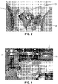
- mice Thirty-six 12 week-old 0F-1 male mice (Charles Rivers, France) were used for this study: Six were used to test infra red laser irradiation on mice brain and thirty were used for nHA in vivo printing They were first anesthetized with Ketamin and Xylazine through intraperitoneal injection. After skin antisepsis (Betadine), an incision was performed in skull midline and the scalp was dissected to expose the calvaria, then the periosteum was carefully peeled off. Two lateral 4 mm wide calvaria bone defects were performed ( Figure 2 ) in each animal with a 4 mm diameter trephine (TBR, Toulouse, France).
- the surgical procedures were performed under constant saline irrigation and care was taken to prevent dura mater injury. Then, the animals were placed inside the bioprinting station for in vivo printing experiments (see below). At the end of the experiment, the soft tissues were repositioned and sutured using 3/0 Vicryl. Animals recovered in a warm environment before being returned to animal facilities.
- MRI Magnetic Resonance Imaging
- a horizontal 4,7 T Biospec system (Bruker, Germany). This system is equipped with a 6 cm gradient insert capable of 950 mT/m maximum strength and 80 ⁇ m rise time.
- Mice were anesthetized with 1.5-2 % isofluorane (Centravet, La Palisse, France) mixed in air and then positioned prone within the magnet, with the head placed at the center of the NMR coil.
- the total number of averages was equal to 24 (6 per I magnitude images) resulting in a total acquisition time of 23 minutes 26 seconds.
- the skull and brain were harvested in blocks, and prepared for demineralized histological sections: The samples were demineralized 12 hours (Decalcifying osseux BAYER, ref 70033, France), then dehydrated in ethanol (70%, 80%, 95%, 100%) then embedded in paraffin. Ten microns coronal sections were cut and stained with Hematoxylin - Eosin-Saffron (HES) and observed under a photomicroscope (Nikon eclipse 80i, The Netherlands). The sections were observed for the presence of inflammation at brain/skull interface.
- HES Hematoxylin - Eosin-Saffron
- the mouse was installed in the holding device configured to receive the mouse and the calvaria defects were positioned to face the ribbon.
- mice Thirty OF1 male mice (12 weeks old) were included within this cohort. After the generation of calvaria bone defects, each animal received the same amount of material, which consisted in 30 stacked layers (20 ⁇ m each) of n-HA printed by HT Bio-LP in the left defect (test site). The controlateral (right) defect was left empty for negative control (control site). Skin was then sutured and animal were returned to animal facilities.
- MRI was used as a non-invasive methodology to evaluate brain inflammation in vivo longitudinally in two animals of the 3 months group at day 7, day 15 and day 30. Parameters used in this study were similar to those presented above.
- X-ray microtomography acquisitions were done for all samples, using a General Electric ⁇ CT. Tension and intensity used for X rays generation were 80 kV and 60 mA, respectively; 800 views were acquired with an exposure time of 3000 ms. The resolution obtained was 0.015 mm.
- Image J Software was used to evaluate unreconstructed surface of the bone defect.
- Statistical analyses were performed using Medcalc® software (Belgium). Comparisons of the three independent groups (unpaired samples: one week, one month and three months) were done with the non parametric Mann-Whitney U-test. Differences were considered significant with p ⁇ 0.05.
- Hydroxyapatite was chosen because it is the major non-organic component of bone.
- mice over thirty male mice, twenty-nine recovered after the whole process, including surgical sequence and further laser printing experiments. Neither wound infection nor neurological disorders were developed in the animals after surgery and n-HA printing. In addition, after bone defect achievement, dura mater was checked for its integrity, what was confirmed by the presence of pulsating blood vessels.
- n-Ha material was also observed in the controlateral defect, an area not being concerned by the printing experiment.
- n-HA can be observed at a distance from the brain surface (control sites, calvaria midline). These n-HA particles may have moved from the printed site due to the absence of immobilization of printed materials into the recipient site. Pressures applied on the skin during suturing and after animal recovery could have thus induced migration of printed n-Ha from the printed defect to the contro-lateral site. In the future, a specific attention will be paid on immobilizing the printed materials and in suturing mouse skin. In this aim, using surgical glue or other biomembranes are envisaged.
- Upgrading medical robots with Bioprinting ability may allow, first, to improve surgical precision. Indeed, while ⁇ L volumes of materials or drugs can be currently handled in the body by surgeons (or actual robots) by using syringes, highly smaller volumes could be deposited using biological printers since these laters can generate droplets of pL volume. Moreover, parallel to volume reduction, spatial resolution will be also largely improved by the use of laser printers or other bioprinters.
- the second experimentation described in relation to Figures 9 to 11 consists in an in vivo printing of MG63 cells transfected by Luciferase enzyme (MG63-Luc) as biological material within a midline mouse calvaria defect.
- MG63-Luc Luciferase enzyme
- the deposited biological material was a solution of MG63 cells transfected by Luciferase enzyme (MG63-Luc).
- Cell concentration was 50 Millions cells/ml and cells were suspended in culture medium supplemented with 0.5 % Alginate (v/v).
- nude mice (Charles River, France) were used to perform a midline calvaria defect of 4 mm wide with diameter trephine burr (TBR Toulouse, France) (see Figure 9 ).
- the preparation of the animal is similar to the above-mentioned procedure.
- the above described biological printing station 1 was used and a ribbon, similar to that described in relation to the first experimentation except for the layer of biological material coating the support, was prepared.
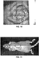
- the mouse as a receiving substrate 3 was placed in the positioning system ( Figure 9 ) with the midline calvaria defect as area of interest facing the opened working area of the holding device and the CCD camera.
- the defect was detected by the CCD camera of the imaging system of the biological printing station as can be seen from Figure 10 showing a video capture of the defect.
- a 3 mm-diameter ring pattern was determined.
- the center of the ring was adjusted to the center of the defect.
- Macroscopic observation performed immediately after bioprinting exhibit the circle of MG63 cells.
- Luciferin was injected intraperitoneaoulsy for Photon imaging (Biospace, France) analysis. Results of immediate photon imager observations are shown in Figure 11 that evidenced the presence of a ring-shape pattern of MG63 cells at the position determined preliminary by the imaging system.
- the third experimentation described in relation to Figure 12 consists in an in vivo printing of murine mesenchymal stem cells (D1 cell line bought from ATCC) transfected by luciferase enzyme as biological material (D1-Luc) within a lateral mouse calvaria defect.
- D1 cell line bought from ATCC
- D1-Luc biological material
- the deposited biological material was a solution of D1 cells transfected by Luciferase enzyme (D1-Luc).
- Cell concentration was 50 Millions cells/ml and cells were suspended in culture medium supplemented with 1 % Alginate (v/v).
- Balb/c (Charles River, France) were used to perform two lateral calvaria defects of 3.3 mm wide with diameter trephine burr (TBR Toulouse, France).
- the preparation of the animal is similar to the above-mentioned procedure.
- the above described biological printing station 1 was used and a ribbon, similar to that described in relation to the second experimentation except for the layer of biological material coating the support, was prepared.
- the mouse as a receiving substrate 3 was placed in the positioning system with one of the lateral calvaria defects as area of interest facing the opened working area of the holding device and the CCD camera.
- the defect was detected by the CCD camera of the imaging system of the biological printing station.
- a ring pattern was determined as follow: outer diameter: 3.2mm and inner diameter: 2.8mm. The center of the ring was adjusted to the center of the defect.
Landscapes
- Health & Medical Sciences (AREA)
- Life Sciences & Earth Sciences (AREA)
- Engineering & Computer Science (AREA)
- Chemical & Material Sciences (AREA)
- Bioinformatics & Cheminformatics (AREA)
- Zoology (AREA)
- Organic Chemistry (AREA)
- Wood Science & Technology (AREA)
- Biomedical Technology (AREA)
- Genetics & Genomics (AREA)
- Biotechnology (AREA)
- General Health & Medical Sciences (AREA)
- General Engineering & Computer Science (AREA)
- Sustainable Development (AREA)
- Microbiology (AREA)
- Biochemistry (AREA)
- Molecular Biology (AREA)
- Clinical Laboratory Science (AREA)
- Chemical Kinetics & Catalysis (AREA)
- Medicinal Chemistry (AREA)
- Apparatus Associated With Microorganisms And Enzymes (AREA)
- Anesthesiology (AREA)
- Hematology (AREA)
- Animal Behavior & Ethology (AREA)
- Public Health (AREA)
- Veterinary Medicine (AREA)
- Heart & Thoracic Surgery (AREA)
- Prostheses (AREA)
Priority Applications (1)
| Application Number | Priority Date | Filing Date | Title |
|---|---|---|---|
| EP11707159.7A EP2542659B1 (en) | 2010-03-04 | 2011-03-04 | Bioprinting station, assembly comprising such bioprinting station and bioprinting method |
Applications Claiming Priority (3)
| Application Number | Priority Date | Filing Date | Title |
|---|---|---|---|
| EP10305224 | 2010-03-04 | ||
| PCT/EP2011/053331 WO2011107599A1 (en) | 2010-03-04 | 2011-03-04 | Bioprinting station, assembly comprising such bioprinting station and bioprinting method |
| EP11707159.7A EP2542659B1 (en) | 2010-03-04 | 2011-03-04 | Bioprinting station, assembly comprising such bioprinting station and bioprinting method |
Publications (2)
| Publication Number | Publication Date |
|---|---|
| EP2542659A1 EP2542659A1 (en) | 2013-01-09 |
| EP2542659B1 true EP2542659B1 (en) | 2018-03-07 |
Family
ID=42950279
Family Applications (1)
| Application Number | Title | Priority Date | Filing Date |
|---|---|---|---|
| EP11707159.7A Active EP2542659B1 (en) | 2010-03-04 | 2011-03-04 | Bioprinting station, assembly comprising such bioprinting station and bioprinting method |
Country Status (5)
| Country | Link |
|---|---|
| US (2) | US9039998B2 (https=) |
| EP (1) | EP2542659B1 (https=) |
| JP (1) | JP5757961B2 (https=) |
| ES (1) | ES2671594T3 (https=) |
| WO (1) | WO2011107599A1 (https=) |
Cited By (1)
| Publication number | Priority date | Publication date | Assignee | Title |
|---|---|---|---|---|
| US12427229B2 (en) | 2020-08-06 | 2025-09-30 | PhosPrint P.C. | Laser ablation/removal and laser induced forward transfer of biological material |
Families Citing this family (69)
| Publication number | Priority date | Publication date | Assignee | Title |
|---|---|---|---|---|
| US8241905B2 (en) | 2004-02-24 | 2012-08-14 | The Curators Of The University Of Missouri | Self-assembling cell aggregates and methods of making engineered tissue using the same |
| JP5624981B2 (ja) | 2008-06-24 | 2014-11-12 | ザ・キュレーターズ・オブ・ザ・ユニバーシティ・オブ・ミズーリThe Curators Ofthe University Of Missouri | 自己集合性多細胞体、および前記多細胞体を用いて3次元の生物構造体を作製する方法 |
| WO2011085225A1 (en) | 2010-01-08 | 2011-07-14 | Wake Forest University Health Sciences | Delivery system |
| AU2011318437B2 (en) | 2010-10-21 | 2015-02-26 | Organovo, Inc. | Devices, systems, and methods for the fabrication of tissue |
| WO2012068170A2 (en) | 2010-11-15 | 2012-05-24 | Jau-Nan Lee | Generation of neural stem cells from human trophoblast stem cells |
| AU2012225644B2 (en) | 2011-03-07 | 2017-05-04 | Wake Forest University Health Sciences | Delivery system |
| KR101616761B1 (ko) * | 2011-08-16 | 2016-04-29 | 에이에스엠엘 네델란즈 비.브이. | 리소그래피 장치, 프로그램가능한 패터닝 디바이스 및 리소그래피 방법 |
| HK1200483A1 (en) | 2011-09-12 | 2015-08-07 | 奥加诺沃公司 | Engineered tissues for in vitro research uses, arrays thereof, and methods of making the same |
| GB201119032D0 (en) | 2011-11-03 | 2011-12-14 | Isis Innovation | Multisomes: encapsulated droplet networks |
| US9499779B2 (en) * | 2012-04-20 | 2016-11-22 | Organovo, Inc. | Devices, systems, and methods for the fabrication of tissue utilizing UV cross-linking |
| US10668762B2 (en) * | 2012-10-21 | 2020-06-02 | Precise Bio Inc. | Multi-technology printing system |
| US9446618B2 (en) * | 2012-10-21 | 2016-09-20 | Photon Jet Ltd | Multi-technology printing system |
| GB201219196D0 (en) | 2012-10-25 | 2012-12-12 | Isis Innovation | Droplet assembly method |
| GB201219201D0 (en) | 2012-10-25 | 2012-12-12 | Isis Innovation | Hydrogel network |
| EP2731126A1 (en) | 2012-11-09 | 2014-05-14 | Nederlandse Organisatie voor toegepast -natuurwetenschappelijk onderzoek TNO | Method for bonding bare chip dies |
| WO2014085493A1 (en) | 2012-11-30 | 2014-06-05 | Jau-Nan Lee | Methods of differentiating stem cells by modulating mir-124 |
| KR102449271B1 (ko) | 2012-12-07 | 2022-09-29 | 옥스포드 유니버시티 이노베이션 리미티드 | 3d 프린팅에 의한 비말 어셈블리 |
| WO2014110590A1 (en) | 2013-01-14 | 2014-07-17 | Scripps Health | Tissue array printing |
| US9442105B2 (en) | 2013-03-15 | 2016-09-13 | Organovo, Inc. | Engineered liver tissues, arrays thereof, and methods of making the same |
| US10150258B2 (en) | 2013-07-29 | 2018-12-11 | Carnegie Mellon University | Additive manufacturing of embedded materials |
| SG11201600770RA (en) | 2013-07-31 | 2016-02-26 | Organovo Inc | Automated devices, systems, and methods for the fabrication of tissue |
| JP6612760B2 (ja) * | 2013-10-11 | 2019-11-27 | アドバンスト・ソリューションズ・ライフ・サイエンシズ,エルエルシー | 生体材料構造体の設計、製作、および組み立てシステムならびにワークステーション |
| US11903612B2 (en) | 2013-11-04 | 2024-02-20 | University Of Iowa Research Foundation | Bioprinter and methods of using same |
| EP2896717A1 (en) * | 2014-01-15 | 2015-07-22 | Nanotechplasma SARL | Laser direct synthesis and deposit of nanocomposite materials or nanostructures |
| JP2017514643A (ja) | 2014-03-25 | 2017-06-08 | バイオボット、インコーポレイテッド | 電磁放射線を利用する材料及び組織の製造のための方法、デバイス、及びシステム |
| EP3808838B1 (en) | 2014-04-04 | 2024-04-10 | Organovo, Inc. | Engineered three-dimensional breast tissue, adipose tissue, and tumor disease model |
| US9764515B2 (en) | 2014-05-01 | 2017-09-19 | Musc Foundation For Research Development | Multidispensor cartesian robotic printer |
| KR20170064547A (ko) | 2014-10-06 | 2017-06-09 | 오가노보, 인크. | 조작된 신장 조직, 이의 어레이, 및 이를 제조하는 방법 |
| US11529436B2 (en) | 2014-11-05 | 2022-12-20 | Organovo, Inc. | Engineered three-dimensional skin tissues, arrays thereof, and methods of making the same |
| US9808490B2 (en) | 2014-11-26 | 2017-11-07 | Accelerated Biosciences Corp. | Induced hepatocytes and uses thereof |
| FR3030360B1 (fr) | 2014-12-17 | 2018-07-13 | Universite de Bordeaux | Procede d'impression par laser et dispositif pour sa mise en oeuvre |
| FR3030361B1 (fr) * | 2014-12-17 | 2017-01-20 | Univ Bordeaux | Procede d'impression d'elements biologiques par laser et dispositif pour sa mise en oeuvre |
| US10046091B2 (en) | 2015-03-20 | 2018-08-14 | Elwha Llc | Printing systems and related methods |
| USD760825S1 (en) | 2015-03-25 | 2016-07-05 | Biobots, Inc. | Bioprinter |
| EP3912577B1 (en) | 2015-06-23 | 2025-04-09 | Stryker Corporation | Delivery system for delivering material to a target site |
| KR102078602B1 (ko) * | 2015-07-23 | 2020-02-19 | 한국화학연구원 | 지방세포와 마크로파지의 3차원 공동 배양 방법 |
| US11788042B2 (en) | 2015-07-31 | 2023-10-17 | Redwire Space Technologies, Inc. | Biomanufacturing system, method, and 3D bioprinting hardware in a reduced gravity environment |
| US10655096B2 (en) | 2015-07-31 | 2020-05-19 | Techshot, Inc. | Biomanufacturing system, method, and 3D bioprinting hardware in a reduced gravity environment |
| EP3344400B1 (en) | 2015-09-04 | 2022-07-20 | The General Hospital Corporation | Three dimensional microtissue bioprinter |
| EP3359641B1 (en) | 2015-10-09 | 2020-01-08 | DEKA Products Limited Partnership | Fluid pumping and bioreactor system |
| WO2017083402A1 (en) | 2015-11-09 | 2017-05-18 | Organovo, Inc. | Improved methods for tissue fabrication |
| US10433921B2 (en) | 2015-12-28 | 2019-10-08 | Mako Surgical Corp. | Apparatus and methods for robot assisted bone treatment |
| US10675442B2 (en) | 2016-02-08 | 2020-06-09 | Nextern, Inc. | Robotically augmented catheter manipulation handle |
| US10888428B2 (en) | 2016-05-12 | 2021-01-12 | University Of Notre Dame Du Lac | Additive manufacturing device for biomaterials |
| EP3463169B1 (en) * | 2016-05-26 | 2023-07-19 | Scripps Health | Systems to repair tissue defects |
| AU2017204355B2 (en) | 2016-07-08 | 2021-09-09 | Mako Surgical Corp. | Scaffold for alloprosthetic composite implant |
| US10345208B2 (en) | 2016-07-12 | 2019-07-09 | Deka Products Limited Partnership | System and method for applying force to a device |
| US11254901B2 (en) | 2016-07-12 | 2022-02-22 | Deka Products Limited Partnership | System and method for printing tissue |
| US20180033609A1 (en) * | 2016-07-28 | 2018-02-01 | QMAT, Inc. | Removal of non-cleaved/non-transferred material from donor substrate |
| US11299705B2 (en) | 2016-11-07 | 2022-04-12 | Deka Products Limited Partnership | System and method for creating tissue |
| WO2018094504A1 (en) * | 2016-11-23 | 2018-05-31 | Institut National De La Recherche Scientifique | Method and system of laser-driven impact acceleration |
| FR3063932B1 (fr) * | 2017-03-15 | 2019-03-22 | Universite de Bordeaux | Equipement et procede pour le depot de particules sur une cible |
| FR3063931B1 (fr) * | 2017-03-15 | 2019-03-22 | Poietis | Equipement et procede d'impression additive |
| FR3063930B1 (fr) * | 2017-03-15 | 2019-03-22 | Poietis | Procede de bioimpression |
| US10570362B2 (en) | 2017-07-12 | 2020-02-25 | Deka Products Limited Partnership | System and method for transferring tissue |
| US12297416B2 (en) | 2017-07-12 | 2025-05-13 | Deka Products Limited Partneship | System and method for transferring tissue |
| DE102018005010A1 (de) * | 2017-07-13 | 2019-01-17 | Wika Alexander Wiegand Se & Co. Kg | Transfer und Aufschmelzen von Schichten |
| WO2019034954A1 (en) * | 2017-08-17 | 2019-02-21 | Clear-Cut Medical Ltd. | FABRIC MARKING SYSTEM |
| SE1850073A1 (en) * | 2018-01-24 | 2019-07-25 | Cellink Ab | 3D bioprinters |
| FR3082123B1 (fr) | 2018-06-07 | 2020-10-16 | Urgo Rech Innovation Et Developpement | Pansement cellularise et son procede de fabrication |
| FR3087703B1 (fr) * | 2018-10-25 | 2020-12-04 | Poietis | Systeme de bio-impression robotise |
| EP3877748A4 (en) * | 2018-11-06 | 2022-11-09 | Cellino Biotech, Inc. | Systems for cell control |
| EP3670665A1 (en) | 2018-12-20 | 2020-06-24 | Hochschule Für Angewandte Wissenschaften München | Laser-induced cell transfer and sorting |
| FR3093944B1 (fr) * | 2019-03-22 | 2021-03-19 | Poietis | Cartouche pour bioimpression |
| EP3983200B1 (en) * | 2019-06-14 | 2023-07-12 | IO Tech Group Ltd. | Additive manufacturing of a free form object made of multicomponent materials |
| AU2021261864A1 (en) | 2020-11-03 | 2022-05-19 | Mako Surgical Corp. | Multi-component locking implant |
| LU102294B1 (en) * | 2020-12-17 | 2022-06-21 | Fyzikalni Ustav Av Cr V V I | A method and a device for assembly of a nanomaterial structure |
| JPWO2023195492A1 (https=) * | 2022-04-06 | 2023-10-12 | ||
| GR1010614B (el) * | 2023-01-27 | 2024-01-23 | Εθνικο Μετσοβιο Πολυτεχνειο, | Μεθοδος εκτυπωσης φαρμακων με λεϊζερ και συστημα εφαρμογης αυτης |
Citations (2)
| Publication number | Priority date | Publication date | Assignee | Title |
|---|---|---|---|---|
| US20030157271A1 (en) * | 2001-01-19 | 2003-08-21 | Duignan Michael T. | Method and apparatus for pulse-position synchronization in miniature structures manufacturing processes |
| US6864101B1 (en) * | 1991-11-22 | 2005-03-08 | Affymetrix, Inc. | Combinatorial strategies for polymer synthesis |
Family Cites Families (8)
| Publication number | Priority date | Publication date | Assignee | Title |
|---|---|---|---|---|
| US6177151B1 (en) * | 1999-01-27 | 2001-01-23 | The United States Of America As Represented By The Secretary Of The Navy | Matrix assisted pulsed laser evaporation direct write |
| EP2363828A1 (en) * | 2000-10-24 | 2011-09-07 | Cyntellect, Inc. | Device for selectively targeting cells within a three-dimensional specimen |
| GR1004059B (el) * | 2001-12-31 | 2002-11-15 | Ιωαννα Ζεργιωτη | Κατασκευη βιοπολυμερικων σχηματων μεσω εναποθεσης με λειζερ. |
| DE10236029A1 (de) * | 2002-08-02 | 2004-02-19 | Cybio Systems Gmbh | Einrichtung zum Dispensieren und Beobachten der Lumineszenz von Einzelproben in Multiprobenanordnungen |
| JP2004202126A (ja) * | 2002-12-26 | 2004-07-22 | Next:Kk | 人工骨成形方法 |
| US7381440B2 (en) * | 2003-06-06 | 2008-06-03 | The United States Of America As Represented By The Secretary Of The Navy | Biological laser printing for tissue microdissection via indirect photon-biomaterial interactions |
| DE102004021904B4 (de) * | 2004-05-04 | 2011-08-18 | Carl Zeiss Microlmaging GmbH, 07745 | Verfahren und Vorrichtung zur Erzeugung einer Analyseanordnung mit diskreten, separaten Messbereichen zur biologischen, biochemischen oder chemischen Analyse |
| WO2011085225A1 (en) | 2010-01-08 | 2011-07-14 | Wake Forest University Health Sciences | Delivery system |
-
2011
- 2011-03-04 US US13/582,145 patent/US9039998B2/en active Active
- 2011-03-04 WO PCT/EP2011/053331 patent/WO2011107599A1/en not_active Ceased
- 2011-03-04 EP EP11707159.7A patent/EP2542659B1/en active Active
- 2011-03-04 JP JP2012555441A patent/JP5757961B2/ja active Active
- 2011-03-04 ES ES11707159.7T patent/ES2671594T3/es active Active
-
2015
- 2015-04-22 US US14/692,821 patent/US9629989B2/en active Active
Patent Citations (2)
| Publication number | Priority date | Publication date | Assignee | Title |
|---|---|---|---|---|
| US6864101B1 (en) * | 1991-11-22 | 2005-03-08 | Affymetrix, Inc. | Combinatorial strategies for polymer synthesis |
| US20030157271A1 (en) * | 2001-01-19 | 2003-08-21 | Duignan Michael T. | Method and apparatus for pulse-position synchronization in miniature structures manufacturing processes |
Cited By (1)
| Publication number | Priority date | Publication date | Assignee | Title |
|---|---|---|---|---|
| US12427229B2 (en) | 2020-08-06 | 2025-09-30 | PhosPrint P.C. | Laser ablation/removal and laser induced forward transfer of biological material |
Also Published As
| Publication number | Publication date |
|---|---|
| US20150224291A1 (en) | 2015-08-13 |
| JP5757961B2 (ja) | 2015-08-05 |
| EP2542659A1 (en) | 2013-01-09 |
| US9629989B2 (en) | 2017-04-25 |
| US20130017564A1 (en) | 2013-01-17 |
| JP2013521033A (ja) | 2013-06-10 |
| ES2671594T3 (es) | 2018-06-07 |
| US9039998B2 (en) | 2015-05-26 |
| WO2011107599A1 (en) | 2011-09-09 |
Similar Documents
| Publication | Publication Date | Title |
|---|---|---|
| EP2542659B1 (en) | Bioprinting station, assembly comprising such bioprinting station and bioprinting method | |
| Keriquel et al. | In vivo bioprinting for computer-and robotic-assisted medical intervention: preliminary study in mice | |
| Singh et al. | In situ bioprinting–bioprinting from benchside to bedside? | |
| Chang et al. | Laser-induced forward transfer based laser bioprinting in biomedical applications | |
| Zhang et al. | Tissue engineering applications of three-dimensional bioprinting | |
| Murphy et al. | 3D bioprinting of tissues and organs | |
| JP2017514643A (ja) | 電磁放射線を利用する材料及び組織の製造のための方法、デバイス、及びシステム | |
| JP7595584B2 (ja) | オルガノイド培養のためのシステムおよび方法 | |
| Starly et al. | 3D bioprinting techniques | |
| Bharadwaj et al. | Open source bioprinters: Revolutionizing the accessibility of biofabrication | |
| Manzoli et al. | An Overview of 3D Bioprinting Impact on Cell Viability: From Damage Assessment to Protection Solutions | |
| EP3870446A1 (fr) | Dispositif de bio-impression isole | |
| Buchberger et al. | Laser Structuring for Biomedical Applications | |
| Mielczarek et al. | A Prototype of a 3D Bioprinter | |
| Catros et al. | In vivo and in situ biofabrication by laser-assisted bioprinting | |
| Sidor et al. | Additive manufacturing of engineered living materials | |
| Venkat et al. | Medical 3D Printing: Techniques, Advances, Applications, Challenges, and Regulatory Implications | |
| Kérourédan et al. | Laser-Assisted Bioprinting for Tissue Engineering | |
| ES3024481T3 (en) | Methods and systems for generating three-dimensional biological structures | |
| Choudhury et al. | Applications of 3D Bioprinting in Anatomical Structure | |
| US20250009939A1 (en) | Vascular bone organoid and its compression-perfusion fabricator system | |
| Kumar et al. | 3D bioprinting techniques for tissue engineering applications | |
| EP1996694A1 (de) | Vorrichtung und verfahren zur kultivierung und generierung von biologischem material in einem nährstoffnebel | |
| US20240228934A9 (en) | Nonclinical method for testing medical device surface interactions with migrating cells in simulated in vivo environment | |
| Kumar et al. | Bioprinting Technologies: Advancing the Future of Regenerative Medicine and Tissue Engineering |
Legal Events
| Date | Code | Title | Description |
|---|---|---|---|
| PUAI | Public reference made under article 153(3) epc to a published international application that has entered the european phase |
Free format text: ORIGINAL CODE: 0009012 |
|
| 17P | Request for examination filed |
Effective date: 20120813 |
|
| AK | Designated contracting states |
Kind code of ref document: A1 Designated state(s): AL AT BE BG CH CY CZ DE DK EE ES FI FR GB GR HR HU IE IS IT LI LT LU LV MC MK MT NL NO PL PT RO RS SE SI SK SM TR |
|
| DAX | Request for extension of the european patent (deleted) | ||
| STAA | Information on the status of an ep patent application or granted ep patent |
Free format text: STATUS: EXAMINATION IS IN PROGRESS |
|
| 17Q | First examination report despatched |
Effective date: 20170509 |
|
| GRAP | Despatch of communication of intention to grant a patent |
Free format text: ORIGINAL CODE: EPIDOSNIGR1 |
|
| STAA | Information on the status of an ep patent application or granted ep patent |
Free format text: STATUS: GRANT OF PATENT IS INTENDED |
|
| INTG | Intention to grant announced |
Effective date: 20171023 |
|
| GRAS | Grant fee paid |
Free format text: ORIGINAL CODE: EPIDOSNIGR3 |
|
| GRAA | (expected) grant |
Free format text: ORIGINAL CODE: 0009210 |
|
| STAA | Information on the status of an ep patent application or granted ep patent |
Free format text: STATUS: THE PATENT HAS BEEN GRANTED |
|
| AK | Designated contracting states |
Kind code of ref document: B1 Designated state(s): AL AT BE BG CH CY CZ DE DK EE ES FI FR GB GR HR HU IE IS IT LI LT LU LV MC MK MT NL NO PL PT RO RS SE SI SK SM TR |
|
| REG | Reference to a national code |
Ref country code: GB Ref legal event code: FG4D |
|
| REG | Reference to a national code |
Ref country code: CH Ref legal event code: EP Ref country code: AT Ref legal event code: REF Ref document number: 976579 Country of ref document: AT Kind code of ref document: T Effective date: 20180315 |
|
| REG | Reference to a national code |
Ref country code: IE Ref legal event code: FG4D |
|
| REG | Reference to a national code |
Ref country code: DE Ref legal event code: R096 Ref document number: 602011046245 Country of ref document: DE |
|
| REG | Reference to a national code |
Ref country code: CH Ref legal event code: NV Representative=s name: ABREMA AGENCE BREVET ET MARQUES, GANGUILLET, CH |
|
| REG | Reference to a national code |
Ref country code: ES Ref legal event code: FG2A Ref document number: 2671594 Country of ref document: ES Kind code of ref document: T3 Effective date: 20180607 |
|
| REG | Reference to a national code |
Ref country code: NL Ref legal event code: FP |
|
| REG | Reference to a national code |
Ref country code: LT Ref legal event code: MG4D |
|
| PG25 | Lapsed in a contracting state [announced via postgrant information from national office to epo] |
Ref country code: FI Free format text: LAPSE BECAUSE OF FAILURE TO SUBMIT A TRANSLATION OF THE DESCRIPTION OR TO PAY THE FEE WITHIN THE PRESCRIBED TIME-LIMIT Effective date: 20180307 Ref country code: NO Free format text: LAPSE BECAUSE OF FAILURE TO SUBMIT A TRANSLATION OF THE DESCRIPTION OR TO PAY THE FEE WITHIN THE PRESCRIBED TIME-LIMIT Effective date: 20180607 Ref country code: CY Free format text: LAPSE BECAUSE OF FAILURE TO SUBMIT A TRANSLATION OF THE DESCRIPTION OR TO PAY THE FEE WITHIN THE PRESCRIBED TIME-LIMIT Effective date: 20180307 Ref country code: HR Free format text: LAPSE BECAUSE OF FAILURE TO SUBMIT A TRANSLATION OF THE DESCRIPTION OR TO PAY THE FEE WITHIN THE PRESCRIBED TIME-LIMIT Effective date: 20180307 Ref country code: LT Free format text: LAPSE BECAUSE OF FAILURE TO SUBMIT A TRANSLATION OF THE DESCRIPTION OR TO PAY THE FEE WITHIN THE PRESCRIBED TIME-LIMIT Effective date: 20180307 |
|
| REG | Reference to a national code |
Ref country code: AT Ref legal event code: MK05 Ref document number: 976579 Country of ref document: AT Kind code of ref document: T Effective date: 20180307 |
|
| PG25 | Lapsed in a contracting state [announced via postgrant information from national office to epo] |
Ref country code: LV Free format text: LAPSE BECAUSE OF FAILURE TO SUBMIT A TRANSLATION OF THE DESCRIPTION OR TO PAY THE FEE WITHIN THE PRESCRIBED TIME-LIMIT Effective date: 20180307 Ref country code: SE Free format text: LAPSE BECAUSE OF FAILURE TO SUBMIT A TRANSLATION OF THE DESCRIPTION OR TO PAY THE FEE WITHIN THE PRESCRIBED TIME-LIMIT Effective date: 20180307 Ref country code: BG Free format text: LAPSE BECAUSE OF FAILURE TO SUBMIT A TRANSLATION OF THE DESCRIPTION OR TO PAY THE FEE WITHIN THE PRESCRIBED TIME-LIMIT Effective date: 20180607 Ref country code: RS Free format text: LAPSE BECAUSE OF FAILURE TO SUBMIT A TRANSLATION OF THE DESCRIPTION OR TO PAY THE FEE WITHIN THE PRESCRIBED TIME-LIMIT Effective date: 20180307 Ref country code: GR Free format text: LAPSE BECAUSE OF FAILURE TO SUBMIT A TRANSLATION OF THE DESCRIPTION OR TO PAY THE FEE WITHIN THE PRESCRIBED TIME-LIMIT Effective date: 20180608 |
|
| PG25 | Lapsed in a contracting state [announced via postgrant information from national office to epo] |
Ref country code: RO Free format text: LAPSE BECAUSE OF FAILURE TO SUBMIT A TRANSLATION OF THE DESCRIPTION OR TO PAY THE FEE WITHIN THE PRESCRIBED TIME-LIMIT Effective date: 20180307 Ref country code: EE Free format text: LAPSE BECAUSE OF FAILURE TO SUBMIT A TRANSLATION OF THE DESCRIPTION OR TO PAY THE FEE WITHIN THE PRESCRIBED TIME-LIMIT Effective date: 20180307 Ref country code: PL Free format text: LAPSE BECAUSE OF FAILURE TO SUBMIT A TRANSLATION OF THE DESCRIPTION OR TO PAY THE FEE WITHIN THE PRESCRIBED TIME-LIMIT Effective date: 20180307 Ref country code: AL Free format text: LAPSE BECAUSE OF FAILURE TO SUBMIT A TRANSLATION OF THE DESCRIPTION OR TO PAY THE FEE WITHIN THE PRESCRIBED TIME-LIMIT Effective date: 20180307 |
|
| PG25 | Lapsed in a contracting state [announced via postgrant information from national office to epo] |
Ref country code: AT Free format text: LAPSE BECAUSE OF FAILURE TO SUBMIT A TRANSLATION OF THE DESCRIPTION OR TO PAY THE FEE WITHIN THE PRESCRIBED TIME-LIMIT Effective date: 20180307 Ref country code: SM Free format text: LAPSE BECAUSE OF FAILURE TO SUBMIT A TRANSLATION OF THE DESCRIPTION OR TO PAY THE FEE WITHIN THE PRESCRIBED TIME-LIMIT Effective date: 20180307 Ref country code: SK Free format text: LAPSE BECAUSE OF FAILURE TO SUBMIT A TRANSLATION OF THE DESCRIPTION OR TO PAY THE FEE WITHIN THE PRESCRIBED TIME-LIMIT Effective date: 20180307 Ref country code: CZ Free format text: LAPSE BECAUSE OF FAILURE TO SUBMIT A TRANSLATION OF THE DESCRIPTION OR TO PAY THE FEE WITHIN THE PRESCRIBED TIME-LIMIT Effective date: 20180307 |
|
| REG | Reference to a national code |
Ref country code: DE Ref legal event code: R097 Ref document number: 602011046245 Country of ref document: DE |
|
| PG25 | Lapsed in a contracting state [announced via postgrant information from national office to epo] |
Ref country code: PT Free format text: LAPSE BECAUSE OF FAILURE TO SUBMIT A TRANSLATION OF THE DESCRIPTION OR TO PAY THE FEE WITHIN THE PRESCRIBED TIME-LIMIT Effective date: 20180709 |
|
| PLBE | No opposition filed within time limit |
Free format text: ORIGINAL CODE: 0009261 |
|
| STAA | Information on the status of an ep patent application or granted ep patent |
Free format text: STATUS: NO OPPOSITION FILED WITHIN TIME LIMIT |
|
| PG25 | Lapsed in a contracting state [announced via postgrant information from national office to epo] |
Ref country code: DK Free format text: LAPSE BECAUSE OF FAILURE TO SUBMIT A TRANSLATION OF THE DESCRIPTION OR TO PAY THE FEE WITHIN THE PRESCRIBED TIME-LIMIT Effective date: 20180307 |
|
| 26N | No opposition filed |
Effective date: 20181210 |
|
| PG25 | Lapsed in a contracting state [announced via postgrant information from national office to epo] |
Ref country code: IT Free format text: LAPSE BECAUSE OF FAILURE TO SUBMIT A TRANSLATION OF THE DESCRIPTION OR TO PAY THE FEE WITHIN THE PRESCRIBED TIME-LIMIT Effective date: 20180307 Ref country code: SI Free format text: LAPSE BECAUSE OF FAILURE TO SUBMIT A TRANSLATION OF THE DESCRIPTION OR TO PAY THE FEE WITHIN THE PRESCRIBED TIME-LIMIT Effective date: 20180307 |
|
| PG25 | Lapsed in a contracting state [announced via postgrant information from national office to epo] |
Ref country code: MC Free format text: LAPSE BECAUSE OF FAILURE TO SUBMIT A TRANSLATION OF THE DESCRIPTION OR TO PAY THE FEE WITHIN THE PRESCRIBED TIME-LIMIT Effective date: 20180307 |
|
| PG25 | Lapsed in a contracting state [announced via postgrant information from national office to epo] |
Ref country code: LU Free format text: LAPSE BECAUSE OF NON-PAYMENT OF DUE FEES Effective date: 20190304 |
|
| PG25 | Lapsed in a contracting state [announced via postgrant information from national office to epo] |
Ref country code: IE Free format text: LAPSE BECAUSE OF NON-PAYMENT OF DUE FEES Effective date: 20190304 |
|
| PG25 | Lapsed in a contracting state [announced via postgrant information from national office to epo] |
Ref country code: TR Free format text: LAPSE BECAUSE OF FAILURE TO SUBMIT A TRANSLATION OF THE DESCRIPTION OR TO PAY THE FEE WITHIN THE PRESCRIBED TIME-LIMIT Effective date: 20180307 |
|
| PG25 | Lapsed in a contracting state [announced via postgrant information from national office to epo] |
Ref country code: MT Free format text: LAPSE BECAUSE OF NON-PAYMENT OF DUE FEES Effective date: 20190304 |
|
| REG | Reference to a national code |
Ref country code: CH Ref legal event code: PFUS Owner name: INSERM (INSTITUT NATIONAL DE LA SANTE ET DE LA, FR Free format text: FORMER OWNER: INSERM (INSTITUT NATIONAL DE LA SANTE ET DE LA RECHERCHE MEDICALE), FR |
|
| PG25 | Lapsed in a contracting state [announced via postgrant information from national office to epo] |
Ref country code: IS Free format text: LAPSE BECAUSE OF FAILURE TO SUBMIT A TRANSLATION OF THE DESCRIPTION OR TO PAY THE FEE WITHIN THE PRESCRIBED TIME-LIMIT Effective date: 20180707 |
|
| PG25 | Lapsed in a contracting state [announced via postgrant information from national office to epo] |
Ref country code: HU Free format text: LAPSE BECAUSE OF FAILURE TO SUBMIT A TRANSLATION OF THE DESCRIPTION OR TO PAY THE FEE WITHIN THE PRESCRIBED TIME-LIMIT; INVALID AB INITIO Effective date: 20110304 |
|
| PG25 | Lapsed in a contracting state [announced via postgrant information from national office to epo] |
Ref country code: MK Free format text: LAPSE BECAUSE OF FAILURE TO SUBMIT A TRANSLATION OF THE DESCRIPTION OR TO PAY THE FEE WITHIN THE PRESCRIBED TIME-LIMIT Effective date: 20180307 |
|
| PGFP | Annual fee paid to national office [announced via postgrant information from national office to epo] |
Ref country code: ES Payment date: 20250425 Year of fee payment: 15 |
|
| PGFP | Annual fee paid to national office [announced via postgrant information from national office to epo] |
Ref country code: CH Payment date: 20250403 Year of fee payment: 15 |
|
| REG | Reference to a national code |
Ref country code: DE Ref legal event code: R082 Ref document number: 602011046245 Country of ref document: DE Representative=s name: HOFFMANN EITLE PATENT- UND RECHTSANWAELTE PART, DE |
|
| REG | Reference to a national code |
Ref country code: CH Ref legal event code: U11 Free format text: ST27 STATUS EVENT CODE: U-0-0-U10-U11 (AS PROVIDED BY THE NATIONAL OFFICE) Effective date: 20260401 |
|
| PGFP | Annual fee paid to national office [announced via postgrant information from national office to epo] |
Ref country code: GB Payment date: 20260331 Year of fee payment: 16 |
|
| PGFP | Annual fee paid to national office [announced via postgrant information from national office to epo] |
Ref country code: DE Payment date: 20260331 Year of fee payment: 16 |
|
| PGFP | Annual fee paid to national office [announced via postgrant information from national office to epo] |
Ref country code: BE Payment date: 20260331 Year of fee payment: 16 |
|
| PGFP | Annual fee paid to national office [announced via postgrant information from national office to epo] |
Ref country code: NL Payment date: 20260331 Year of fee payment: 16 |
|
| PGFP | Annual fee paid to national office [announced via postgrant information from national office to epo] |
Ref country code: FR Payment date: 20260331 Year of fee payment: 16 |