EP3344400B1 - Three dimensional microtissue bioprinter - Google Patents
Three dimensional microtissue bioprinter Download PDFInfo
- Publication number
- EP3344400B1 EP3344400B1 EP16843097.3A EP16843097A EP3344400B1 EP 3344400 B1 EP3344400 B1 EP 3344400B1 EP 16843097 A EP16843097 A EP 16843097A EP 3344400 B1 EP3344400 B1 EP 3344400B1
- Authority
- EP
- European Patent Office
- Prior art keywords
- bioprinter
- bioink
- fluid
- syringe
- microtissue
- Prior art date
- Legal status (The legal status is an assumption and is not a legal conclusion. Google has not performed a legal analysis and makes no representation as to the accuracy of the status listed.)
- Active
Links
- 239000012530 fluid Substances 0.000 claims description 62
- 206010028980 Neoplasm Diseases 0.000 claims description 40
- 230000007547 defect Effects 0.000 claims description 30
- 238000000034 method Methods 0.000 claims description 28
- 210000000845 cartilage Anatomy 0.000 claims description 18
- 230000033001 locomotion Effects 0.000 claims description 18
- 210000000988 bone and bone Anatomy 0.000 claims description 11
- 210000004881 tumor cell Anatomy 0.000 claims description 10
- 238000004891 communication Methods 0.000 claims description 9
- 210000002889 endothelial cell Anatomy 0.000 claims description 8
- 210000003321 cartilage cell Anatomy 0.000 claims description 5
- 238000013537 high throughput screening Methods 0.000 claims description 4
- 150000001875 compounds Chemical class 0.000 claims description 3
- 238000007876 drug discovery Methods 0.000 claims description 3
- 210000002536 stromal cell Anatomy 0.000 claims description 3
- 229940000406 drug candidate Drugs 0.000 claims description 2
- 210000001519 tissue Anatomy 0.000 description 69
- 210000004027 cell Anatomy 0.000 description 45
- 210000002901 mesenchymal stem cell Anatomy 0.000 description 24
- 239000003814 drug Substances 0.000 description 16
- 229940079593 drug Drugs 0.000 description 16
- 239000000017 hydrogel Substances 0.000 description 14
- 238000002513 implantation Methods 0.000 description 14
- 230000003833 cell viability Effects 0.000 description 13
- 239000000463 material Substances 0.000 description 13
- 101000958041 Homo sapiens Musculin Proteins 0.000 description 12
- 210000004271 bone marrow stromal cell Anatomy 0.000 description 11
- 210000005228 liver tissue Anatomy 0.000 description 11
- 239000011159 matrix material Substances 0.000 description 11
- 238000007639 printing Methods 0.000 description 11
- 238000010186 staining Methods 0.000 description 10
- 230000008439 repair process Effects 0.000 description 9
- 238000001727 in vivo Methods 0.000 description 8
- 230000007246 mechanism Effects 0.000 description 8
- 102000010834 Extracellular Matrix Proteins Human genes 0.000 description 7
- 108010037362 Extracellular Matrix Proteins Proteins 0.000 description 7
- 210000002744 extracellular matrix Anatomy 0.000 description 7
- 206010021143 Hypoxia Diseases 0.000 description 6
- 210000001188 articular cartilage Anatomy 0.000 description 6
- 238000011161 development Methods 0.000 description 6
- 230000018109 developmental process Effects 0.000 description 6
- 230000003511 endothelial effect Effects 0.000 description 6
- 230000035572 chemosensitivity Effects 0.000 description 5
- 238000007877 drug screening Methods 0.000 description 5
- 238000007490 hematoxylin and eosin (H&E) staining Methods 0.000 description 5
- 238000000338 in vitro Methods 0.000 description 5
- 238000002347 injection Methods 0.000 description 5
- 239000007924 injection Substances 0.000 description 5
- 210000005229 liver cell Anatomy 0.000 description 5
- 238000012360 testing method Methods 0.000 description 5
- 238000004458 analytical method Methods 0.000 description 4
- 239000002246 antineoplastic agent Substances 0.000 description 4
- 229940041181 antineoplastic drug Drugs 0.000 description 4
- 238000013459 approach Methods 0.000 description 4
- 201000011510 cancer Diseases 0.000 description 4
- 238000010586 diagram Methods 0.000 description 4
- 239000000975 dye Substances 0.000 description 4
- 238000005516 engineering process Methods 0.000 description 4
- 238000000386 microscopy Methods 0.000 description 4
- 239000000203 mixture Substances 0.000 description 4
- XJMOSONTPMZWPB-UHFFFAOYSA-M propidium iodide Chemical compound [I-].[I-].C12=CC(N)=CC=C2C2=CC=C(N)C=C2[N+](CCC[N+](C)(CC)CC)=C1C1=CC=CC=C1 XJMOSONTPMZWPB-UHFFFAOYSA-M 0.000 description 4
- 210000000130 stem cell Anatomy 0.000 description 4
- 238000001356 surgical procedure Methods 0.000 description 4
- 102000008186 Collagen Human genes 0.000 description 3
- 108010035532 Collagen Proteins 0.000 description 3
- 238000003556 assay Methods 0.000 description 3
- 210000001185 bone marrow Anatomy 0.000 description 3
- 238000004113 cell culture Methods 0.000 description 3
- 238000003570 cell viability assay Methods 0.000 description 3
- 229940044683 chemotherapy drug Drugs 0.000 description 3
- 229920001436 collagen Polymers 0.000 description 3
- 238000004624 confocal microscopy Methods 0.000 description 3
- 238000009650 gentamicin protection assay Methods 0.000 description 3
- 238000010438 heat treatment Methods 0.000 description 3
- 230000007954 hypoxia Effects 0.000 description 3
- 230000001146 hypoxic effect Effects 0.000 description 3
- 210000004379 membrane Anatomy 0.000 description 3
- 239000012528 membrane Substances 0.000 description 3
- 238000011275 oncology therapy Methods 0.000 description 3
- 230000003287 optical effect Effects 0.000 description 3
- 229920000642 polymer Polymers 0.000 description 3
- 230000001023 pro-angiogenic effect Effects 0.000 description 3
- 230000035945 sensitivity Effects 0.000 description 3
- 230000017423 tissue regeneration Effects 0.000 description 3
- 230000035899 viability Effects 0.000 description 3
- 239000011800 void material Substances 0.000 description 3
- 206010059866 Drug resistance Diseases 0.000 description 2
- WZUVPPKBWHMQCE-UHFFFAOYSA-N Haematoxylin Chemical compound C12=CC(O)=C(O)C=C2CC2(O)C1C1=CC=C(O)C(O)=C1OC2 WZUVPPKBWHMQCE-UHFFFAOYSA-N 0.000 description 2
- 108010073929 Vascular Endothelial Growth Factor A Proteins 0.000 description 2
- 102000005789 Vascular Endothelial Growth Factors Human genes 0.000 description 2
- 108010019530 Vascular Endothelial Growth Factors Proteins 0.000 description 2
- 230000004931 aggregating effect Effects 0.000 description 2
- 230000004075 alteration Effects 0.000 description 2
- 238000005267 amalgamation Methods 0.000 description 2
- 230000033115 angiogenesis Effects 0.000 description 2
- 230000008901 benefit Effects 0.000 description 2
- 210000002449 bone cell Anatomy 0.000 description 2
- 230000010478 bone regeneration Effects 0.000 description 2
- 230000003848 cartilage regeneration Effects 0.000 description 2
- 210000002950 fibroblast Anatomy 0.000 description 2
- 239000007850 fluorescent dye Substances 0.000 description 2
- 230000004927 fusion Effects 0.000 description 2
- 239000000499 gel Substances 0.000 description 2
- 230000005484 gravity Effects 0.000 description 2
- 230000012010 growth Effects 0.000 description 2
- 210000005003 heart tissue Anatomy 0.000 description 2
- 238000003384 imaging method Methods 0.000 description 2
- 238000012216 screening Methods 0.000 description 2
- 230000000638 stimulation Effects 0.000 description 2
- 230000001225 therapeutic effect Effects 0.000 description 2
- 238000011282 treatment Methods 0.000 description 2
- FHVDTGUDJYJELY-UHFFFAOYSA-N 6-{[2-carboxy-4,5-dihydroxy-6-(phosphanyloxy)oxan-3-yl]oxy}-4,5-dihydroxy-3-phosphanyloxane-2-carboxylic acid Chemical compound O1C(C(O)=O)C(P)C(O)C(O)C1OC1C(C(O)=O)OC(OP)C(O)C1O FHVDTGUDJYJELY-UHFFFAOYSA-N 0.000 description 1
- 108010027529 Bio-glue Proteins 0.000 description 1
- 206010061762 Chondropathy Diseases 0.000 description 1
- 208000030453 Drug-Related Side Effects and Adverse reaction Diseases 0.000 description 1
- 102000016942 Elastin Human genes 0.000 description 1
- 108010014258 Elastin Proteins 0.000 description 1
- 241001465754 Metazoa Species 0.000 description 1
- 229930040373 Paraformaldehyde Natural products 0.000 description 1
- 239000004743 Polypropylene Substances 0.000 description 1
- 206010070863 Toxicity to various agents Diseases 0.000 description 1
- 206010064390 Tumour invasion Diseases 0.000 description 1
- 238000004115 adherent culture Methods 0.000 description 1
- 229940072056 alginate Drugs 0.000 description 1
- 235000010443 alginic acid Nutrition 0.000 description 1
- 229920000615 alginic acid Polymers 0.000 description 1
- 238000010171 animal model Methods 0.000 description 1
- 239000011324 bead Substances 0.000 description 1
- 239000000090 biomarker Substances 0.000 description 1
- 238000001574 biopsy Methods 0.000 description 1
- 230000015572 biosynthetic process Effects 0.000 description 1
- 239000004566 building material Substances 0.000 description 1
- 230000009400 cancer invasion Effects 0.000 description 1
- 210000004413 cardiac myocyte Anatomy 0.000 description 1
- 230000022131 cell cycle Effects 0.000 description 1
- 238000012512 characterization method Methods 0.000 description 1
- 239000003795 chemical substances by application Substances 0.000 description 1
- 210000001612 chondrocyte Anatomy 0.000 description 1
- 210000003711 chorioallantoic membrane Anatomy 0.000 description 1
- 238000004590 computer program Methods 0.000 description 1
- 238000002316 cosmetic surgery Methods 0.000 description 1
- 210000004748 cultured cell Anatomy 0.000 description 1
- 230000034994 death Effects 0.000 description 1
- 231100000517 death Toxicity 0.000 description 1
- 201000010099 disease Diseases 0.000 description 1
- 208000037265 diseases, disorders, signs and symptoms Diseases 0.000 description 1
- 239000000890 drug combination Substances 0.000 description 1
- 238000009509 drug development Methods 0.000 description 1
- 230000036267 drug metabolism Effects 0.000 description 1
- 238000001035 drying Methods 0.000 description 1
- 229920002549 elastin Polymers 0.000 description 1
- 230000005611 electricity Effects 0.000 description 1
- 210000001671 embryonic stem cell Anatomy 0.000 description 1
- 230000002708 enhancing effect Effects 0.000 description 1
- YQGOJNYOYNNSMM-UHFFFAOYSA-N eosin Chemical compound [Na+].OC(=O)C1=CC=CC=C1C1=C2C=C(Br)C(=O)C(Br)=C2OC2=C(Br)C(O)=C(Br)C=C21 YQGOJNYOYNNSMM-UHFFFAOYSA-N 0.000 description 1
- 238000000407 epitaxy Methods 0.000 description 1
- 238000001125 extrusion Methods 0.000 description 1
- 238000000799 fluorescence microscopy Methods 0.000 description 1
- 238000012632 fluorescent imaging Methods 0.000 description 1
- 238000012835 hanging drop method Methods 0.000 description 1
- 210000003494 hepatocyte Anatomy 0.000 description 1
- 102000046949 human MSC Human genes 0.000 description 1
- 210000005260 human cell Anatomy 0.000 description 1
- 230000010354 integration Effects 0.000 description 1
- 230000009545 invasion Effects 0.000 description 1
- 210000003127 knee Anatomy 0.000 description 1
- 239000011344 liquid material Substances 0.000 description 1
- 230000004060 metabolic process Effects 0.000 description 1
- 230000003278 mimic effect Effects 0.000 description 1
- 238000002324 minimally invasive surgery Methods 0.000 description 1
- 230000000877 morphologic effect Effects 0.000 description 1
- 210000000963 osteoblast Anatomy 0.000 description 1
- 229920002866 paraformaldehyde Polymers 0.000 description 1
- 230000001575 pathological effect Effects 0.000 description 1
- 238000002135 phase contrast microscopy Methods 0.000 description 1
- 210000001778 pluripotent stem cell Anatomy 0.000 description 1
- -1 polypropylene Polymers 0.000 description 1
- 229920001155 polypropylene Polymers 0.000 description 1
- 238000001959 radiotherapy Methods 0.000 description 1
- 230000008261 resistance mechanism Effects 0.000 description 1
- 238000001338 self-assembly Methods 0.000 description 1
- 239000000243 solution Substances 0.000 description 1
- 241000894007 species Species 0.000 description 1
- 231100000419 toxicity Toxicity 0.000 description 1
- 230000001988 toxicity Effects 0.000 description 1
- 231100000041 toxicology testing Toxicity 0.000 description 1
- 210000003606 umbilical vein Anatomy 0.000 description 1
- 230000037303 wrinkles Effects 0.000 description 1
Images


Classifications
-
- A—HUMAN NECESSITIES
- A61—MEDICAL OR VETERINARY SCIENCE; HYGIENE
- A61L—METHODS OR APPARATUS FOR STERILISING MATERIALS OR OBJECTS IN GENERAL; DISINFECTION, STERILISATION OR DEODORISATION OF AIR; CHEMICAL ASPECTS OF BANDAGES, DRESSINGS, ABSORBENT PADS OR SURGICAL ARTICLES; MATERIALS FOR BANDAGES, DRESSINGS, ABSORBENT PADS OR SURGICAL ARTICLES
- A61L27/00—Materials for grafts or prostheses or for coating grafts or prostheses
- A61L27/36—Materials for grafts or prostheses or for coating grafts or prostheses containing ingredients of undetermined constitution or reaction products thereof, e.g. transplant tissue, natural bone, extracellular matrix
- A61L27/38—Materials for grafts or prostheses or for coating grafts or prostheses containing ingredients of undetermined constitution or reaction products thereof, e.g. transplant tissue, natural bone, extracellular matrix containing added animal cells
- A61L27/3804—Materials for grafts or prostheses or for coating grafts or prostheses containing ingredients of undetermined constitution or reaction products thereof, e.g. transplant tissue, natural bone, extracellular matrix containing added animal cells characterised by specific cells or progenitors thereof, e.g. fibroblasts, connective tissue cells, kidney cells
- A61L27/3834—Cells able to produce different cell types, e.g. hematopoietic stem cells, mesenchymal stem cells, marrow stromal cells, embryonic stem cells
-
- A—HUMAN NECESSITIES
- A61—MEDICAL OR VETERINARY SCIENCE; HYGIENE
- A61L—METHODS OR APPARATUS FOR STERILISING MATERIALS OR OBJECTS IN GENERAL; DISINFECTION, STERILISATION OR DEODORISATION OF AIR; CHEMICAL ASPECTS OF BANDAGES, DRESSINGS, ABSORBENT PADS OR SURGICAL ARTICLES; MATERIALS FOR BANDAGES, DRESSINGS, ABSORBENT PADS OR SURGICAL ARTICLES
- A61L27/00—Materials for grafts or prostheses or for coating grafts or prostheses
- A61L27/36—Materials for grafts or prostheses or for coating grafts or prostheses containing ingredients of undetermined constitution or reaction products thereof, e.g. transplant tissue, natural bone, extracellular matrix
- A61L27/38—Materials for grafts or prostheses or for coating grafts or prostheses containing ingredients of undetermined constitution or reaction products thereof, e.g. transplant tissue, natural bone, extracellular matrix containing added animal cells
- A61L27/3804—Materials for grafts or prostheses or for coating grafts or prostheses containing ingredients of undetermined constitution or reaction products thereof, e.g. transplant tissue, natural bone, extracellular matrix containing added animal cells characterised by specific cells or progenitors thereof, e.g. fibroblasts, connective tissue cells, kidney cells
-
- A—HUMAN NECESSITIES
- A61—MEDICAL OR VETERINARY SCIENCE; HYGIENE
- A61L—METHODS OR APPARATUS FOR STERILISING MATERIALS OR OBJECTS IN GENERAL; DISINFECTION, STERILISATION OR DEODORISATION OF AIR; CHEMICAL ASPECTS OF BANDAGES, DRESSINGS, ABSORBENT PADS OR SURGICAL ARTICLES; MATERIALS FOR BANDAGES, DRESSINGS, ABSORBENT PADS OR SURGICAL ARTICLES
- A61L27/00—Materials for grafts or prostheses or for coating grafts or prostheses
- A61L27/36—Materials for grafts or prostheses or for coating grafts or prostheses containing ingredients of undetermined constitution or reaction products thereof, e.g. transplant tissue, natural bone, extracellular matrix
- A61L27/38—Materials for grafts or prostheses or for coating grafts or prostheses containing ingredients of undetermined constitution or reaction products thereof, e.g. transplant tissue, natural bone, extracellular matrix containing added animal cells
- A61L27/3839—Materials for grafts or prostheses or for coating grafts or prostheses containing ingredients of undetermined constitution or reaction products thereof, e.g. transplant tissue, natural bone, extracellular matrix containing added animal cells characterised by the site of application in the body
- A61L27/3843—Connective tissue
- A61L27/3847—Bones
-
- A—HUMAN NECESSITIES
- A61—MEDICAL OR VETERINARY SCIENCE; HYGIENE
- A61L—METHODS OR APPARATUS FOR STERILISING MATERIALS OR OBJECTS IN GENERAL; DISINFECTION, STERILISATION OR DEODORISATION OF AIR; CHEMICAL ASPECTS OF BANDAGES, DRESSINGS, ABSORBENT PADS OR SURGICAL ARTICLES; MATERIALS FOR BANDAGES, DRESSINGS, ABSORBENT PADS OR SURGICAL ARTICLES
- A61L27/00—Materials for grafts or prostheses or for coating grafts or prostheses
- A61L27/36—Materials for grafts or prostheses or for coating grafts or prostheses containing ingredients of undetermined constitution or reaction products thereof, e.g. transplant tissue, natural bone, extracellular matrix
- A61L27/38—Materials for grafts or prostheses or for coating grafts or prostheses containing ingredients of undetermined constitution or reaction products thereof, e.g. transplant tissue, natural bone, extracellular matrix containing added animal cells
- A61L27/3839—Materials for grafts or prostheses or for coating grafts or prostheses containing ingredients of undetermined constitution or reaction products thereof, e.g. transplant tissue, natural bone, extracellular matrix containing added animal cells characterised by the site of application in the body
- A61L27/3843—Connective tissue
- A61L27/3852—Cartilage, e.g. meniscus
-
- A—HUMAN NECESSITIES
- A61—MEDICAL OR VETERINARY SCIENCE; HYGIENE
- A61L—METHODS OR APPARATUS FOR STERILISING MATERIALS OR OBJECTS IN GENERAL; DISINFECTION, STERILISATION OR DEODORISATION OF AIR; CHEMICAL ASPECTS OF BANDAGES, DRESSINGS, ABSORBENT PADS OR SURGICAL ARTICLES; MATERIALS FOR BANDAGES, DRESSINGS, ABSORBENT PADS OR SURGICAL ARTICLES
- A61L27/00—Materials for grafts or prostheses or for coating grafts or prostheses
- A61L27/50—Materials characterised by their function or physical properties, e.g. injectable or lubricating compositions, shape-memory materials, surface modified materials
-
- B—PERFORMING OPERATIONS; TRANSPORTING
- B01—PHYSICAL OR CHEMICAL PROCESSES OR APPARATUS IN GENERAL
- B01L—CHEMICAL OR PHYSICAL LABORATORY APPARATUS FOR GENERAL USE
- B01L3/00—Containers or dishes for laboratory use, e.g. laboratory glassware; Droppers
- B01L3/02—Burettes; Pipettes
- B01L3/0241—Drop counters; Drop formers
- B01L3/0268—Drop counters; Drop formers using pulse dispensing or spraying, eg. inkjet type, piezo actuated ejection of droplets from capillaries
-
- B—PERFORMING OPERATIONS; TRANSPORTING
- B29—WORKING OF PLASTICS; WORKING OF SUBSTANCES IN A PLASTIC STATE IN GENERAL
- B29C—SHAPING OR JOINING OF PLASTICS; SHAPING OF MATERIAL IN A PLASTIC STATE, NOT OTHERWISE PROVIDED FOR; AFTER-TREATMENT OF THE SHAPED PRODUCTS, e.g. REPAIRING
- B29C64/00—Additive manufacturing, i.e. manufacturing of three-dimensional [3D] objects by additive deposition, additive agglomeration or additive layering, e.g. by 3D printing, stereolithography or selective laser sintering
- B29C64/10—Processes of additive manufacturing
- B29C64/106—Processes of additive manufacturing using only liquids or viscous materials, e.g. depositing a continuous bead of viscous material
- B29C64/112—Processes of additive manufacturing using only liquids or viscous materials, e.g. depositing a continuous bead of viscous material using individual droplets, e.g. from jetting heads
-
- B—PERFORMING OPERATIONS; TRANSPORTING
- B29—WORKING OF PLASTICS; WORKING OF SUBSTANCES IN A PLASTIC STATE IN GENERAL
- B29C—SHAPING OR JOINING OF PLASTICS; SHAPING OF MATERIAL IN A PLASTIC STATE, NOT OTHERWISE PROVIDED FOR; AFTER-TREATMENT OF THE SHAPED PRODUCTS, e.g. REPAIRING
- B29C64/00—Additive manufacturing, i.e. manufacturing of three-dimensional [3D] objects by additive deposition, additive agglomeration or additive layering, e.g. by 3D printing, stereolithography or selective laser sintering
- B29C64/20—Apparatus for additive manufacturing; Details thereof or accessories therefor
- B29C64/205—Means for applying layers
- B29C64/209—Heads; Nozzles
-
- B—PERFORMING OPERATIONS; TRANSPORTING
- B33—ADDITIVE MANUFACTURING TECHNOLOGY
- B33Y—ADDITIVE MANUFACTURING, i.e. MANUFACTURING OF THREE-DIMENSIONAL [3-D] OBJECTS BY ADDITIVE DEPOSITION, ADDITIVE AGGLOMERATION OR ADDITIVE LAYERING, e.g. BY 3-D PRINTING, STEREOLITHOGRAPHY OR SELECTIVE LASER SINTERING
- B33Y10/00—Processes of additive manufacturing
-
- B—PERFORMING OPERATIONS; TRANSPORTING
- B33—ADDITIVE MANUFACTURING TECHNOLOGY
- B33Y—ADDITIVE MANUFACTURING, i.e. MANUFACTURING OF THREE-DIMENSIONAL [3-D] OBJECTS BY ADDITIVE DEPOSITION, ADDITIVE AGGLOMERATION OR ADDITIVE LAYERING, e.g. BY 3-D PRINTING, STEREOLITHOGRAPHY OR SELECTIVE LASER SINTERING
- B33Y30/00—Apparatus for additive manufacturing; Details thereof or accessories therefor
-
- B—PERFORMING OPERATIONS; TRANSPORTING
- B33—ADDITIVE MANUFACTURING TECHNOLOGY
- B33Y—ADDITIVE MANUFACTURING, i.e. MANUFACTURING OF THREE-DIMENSIONAL [3-D] OBJECTS BY ADDITIVE DEPOSITION, ADDITIVE AGGLOMERATION OR ADDITIVE LAYERING, e.g. BY 3-D PRINTING, STEREOLITHOGRAPHY OR SELECTIVE LASER SINTERING
- B33Y50/00—Data acquisition or data processing for additive manufacturing
- B33Y50/02—Data acquisition or data processing for additive manufacturing for controlling or regulating additive manufacturing processes
-
- B—PERFORMING OPERATIONS; TRANSPORTING
- B41—PRINTING; LINING MACHINES; TYPEWRITERS; STAMPS
- B41J—TYPEWRITERS; SELECTIVE PRINTING MECHANISMS, i.e. MECHANISMS PRINTING OTHERWISE THAN FROM A FORME; CORRECTION OF TYPOGRAPHICAL ERRORS
- B41J2/00—Typewriters or selective printing mechanisms characterised by the printing or marking process for which they are designed
- B41J2/005—Typewriters or selective printing mechanisms characterised by the printing or marking process for which they are designed characterised by bringing liquid or particles selectively into contact with a printing material
- B41J2/01—Ink jet
- B41J2/015—Ink jet characterised by the jet generation process
- B41J2/04—Ink jet characterised by the jet generation process generating single droplets or particles on demand
-
- C—CHEMISTRY; METALLURGY
- C12—BIOCHEMISTRY; BEER; SPIRITS; WINE; VINEGAR; MICROBIOLOGY; ENZYMOLOGY; MUTATION OR GENETIC ENGINEERING
- C12M—APPARATUS FOR ENZYMOLOGY OR MICROBIOLOGY; APPARATUS FOR CULTURING MICROORGANISMS FOR PRODUCING BIOMASS, FOR GROWING CELLS OR FOR OBTAINING FERMENTATION OR METABOLIC PRODUCTS, i.e. BIOREACTORS OR FERMENTERS
- C12M21/00—Bioreactors or fermenters specially adapted for specific uses
- C12M21/08—Bioreactors or fermenters specially adapted for specific uses for producing artificial tissue or for ex-vivo cultivation of tissue
-
- C—CHEMISTRY; METALLURGY
- C12—BIOCHEMISTRY; BEER; SPIRITS; WINE; VINEGAR; MICROBIOLOGY; ENZYMOLOGY; MUTATION OR GENETIC ENGINEERING
- C12M—APPARATUS FOR ENZYMOLOGY OR MICROBIOLOGY; APPARATUS FOR CULTURING MICROORGANISMS FOR PRODUCING BIOMASS, FOR GROWING CELLS OR FOR OBTAINING FERMENTATION OR METABOLIC PRODUCTS, i.e. BIOREACTORS OR FERMENTERS
- C12M33/00—Means for introduction, transport, positioning, extraction, harvesting, peeling or sampling of biological material in or from the apparatus
-
- C—CHEMISTRY; METALLURGY
- C12—BIOCHEMISTRY; BEER; SPIRITS; WINE; VINEGAR; MICROBIOLOGY; ENZYMOLOGY; MUTATION OR GENETIC ENGINEERING
- C12N—MICROORGANISMS OR ENZYMES; COMPOSITIONS THEREOF; PROPAGATING, PRESERVING, OR MAINTAINING MICROORGANISMS; MUTATION OR GENETIC ENGINEERING; CULTURE MEDIA
- C12N5/00—Undifferentiated human, animal or plant cells, e.g. cell lines; Tissues; Cultivation or maintenance thereof; Culture media therefor
- C12N5/06—Animal cells or tissues; Human cells or tissues
- C12N5/0602—Vertebrate cells
- C12N5/067—Hepatocytes
- C12N5/0671—Three-dimensional culture, tissue culture or organ culture; Encapsulated cells
-
- C—CHEMISTRY; METALLURGY
- C12—BIOCHEMISTRY; BEER; SPIRITS; WINE; VINEGAR; MICROBIOLOGY; ENZYMOLOGY; MUTATION OR GENETIC ENGINEERING
- C12N—MICROORGANISMS OR ENZYMES; COMPOSITIONS THEREOF; PROPAGATING, PRESERVING, OR MAINTAINING MICROORGANISMS; MUTATION OR GENETIC ENGINEERING; CULTURE MEDIA
- C12N5/00—Undifferentiated human, animal or plant cells, e.g. cell lines; Tissues; Cultivation or maintenance thereof; Culture media therefor
- C12N5/06—Animal cells or tissues; Human cells or tissues
- C12N5/0697—Artificial constructs associating cells of different lineages, e.g. tissue equivalents
-
- G—PHYSICS
- G01—MEASURING; TESTING
- G01N—INVESTIGATING OR ANALYSING MATERIALS BY DETERMINING THEIR CHEMICAL OR PHYSICAL PROPERTIES
- G01N33/00—Investigating or analysing materials by specific methods not covered by groups G01N1/00 - G01N31/00
- G01N33/48—Biological material, e.g. blood, urine; Haemocytometers
- G01N33/50—Chemical analysis of biological material, e.g. blood, urine; Testing involving biospecific ligand binding methods; Immunological testing
- G01N33/5005—Chemical analysis of biological material, e.g. blood, urine; Testing involving biospecific ligand binding methods; Immunological testing involving human or animal cells
- G01N33/5008—Chemical analysis of biological material, e.g. blood, urine; Testing involving biospecific ligand binding methods; Immunological testing involving human or animal cells for testing or evaluating the effect of chemical or biological compounds, e.g. drugs, cosmetics
- G01N33/5011—Chemical analysis of biological material, e.g. blood, urine; Testing involving biospecific ligand binding methods; Immunological testing involving human or animal cells for testing or evaluating the effect of chemical or biological compounds, e.g. drugs, cosmetics for testing antineoplastic activity
-
- A—HUMAN NECESSITIES
- A61—MEDICAL OR VETERINARY SCIENCE; HYGIENE
- A61L—METHODS OR APPARATUS FOR STERILISING MATERIALS OR OBJECTS IN GENERAL; DISINFECTION, STERILISATION OR DEODORISATION OF AIR; CHEMICAL ASPECTS OF BANDAGES, DRESSINGS, ABSORBENT PADS OR SURGICAL ARTICLES; MATERIALS FOR BANDAGES, DRESSINGS, ABSORBENT PADS OR SURGICAL ARTICLES
- A61L2400/00—Materials characterised by their function or physical properties
- A61L2400/06—Flowable or injectable implant compositions
-
- A—HUMAN NECESSITIES
- A61—MEDICAL OR VETERINARY SCIENCE; HYGIENE
- A61L—METHODS OR APPARATUS FOR STERILISING MATERIALS OR OBJECTS IN GENERAL; DISINFECTION, STERILISATION OR DEODORISATION OF AIR; CHEMICAL ASPECTS OF BANDAGES, DRESSINGS, ABSORBENT PADS OR SURGICAL ARTICLES; MATERIALS FOR BANDAGES, DRESSINGS, ABSORBENT PADS OR SURGICAL ARTICLES
- A61L2430/00—Materials or treatment for tissue regeneration
- A61L2430/02—Materials or treatment for tissue regeneration for reconstruction of bones; weight-bearing implants
-
- A—HUMAN NECESSITIES
- A61—MEDICAL OR VETERINARY SCIENCE; HYGIENE
- A61L—METHODS OR APPARATUS FOR STERILISING MATERIALS OR OBJECTS IN GENERAL; DISINFECTION, STERILISATION OR DEODORISATION OF AIR; CHEMICAL ASPECTS OF BANDAGES, DRESSINGS, ABSORBENT PADS OR SURGICAL ARTICLES; MATERIALS FOR BANDAGES, DRESSINGS, ABSORBENT PADS OR SURGICAL ARTICLES
- A61L2430/00—Materials or treatment for tissue regeneration
- A61L2430/06—Materials or treatment for tissue regeneration for cartilage reconstruction, e.g. meniscus
-
- B—PERFORMING OPERATIONS; TRANSPORTING
- B01—PHYSICAL OR CHEMICAL PROCESSES OR APPARATUS IN GENERAL
- B01L—CHEMICAL OR PHYSICAL LABORATORY APPARATUS FOR GENERAL USE
- B01L2200/00—Solutions for specific problems relating to chemical or physical laboratory apparatus
- B01L2200/06—Fluid handling related problems
- B01L2200/0673—Handling of plugs of fluid surrounded by immiscible fluid
-
- B—PERFORMING OPERATIONS; TRANSPORTING
- B01—PHYSICAL OR CHEMICAL PROCESSES OR APPARATUS IN GENERAL
- B01L—CHEMICAL OR PHYSICAL LABORATORY APPARATUS FOR GENERAL USE
- B01L2300/00—Additional constructional details
- B01L2300/18—Means for temperature control
- B01L2300/1805—Conductive heating, heat from thermostatted solids is conducted to receptacles, e.g. heating plates, blocks
- B01L2300/1822—Conductive heating, heat from thermostatted solids is conducted to receptacles, e.g. heating plates, blocks using Peltier elements
-
- B—PERFORMING OPERATIONS; TRANSPORTING
- B01—PHYSICAL OR CHEMICAL PROCESSES OR APPARATUS IN GENERAL
- B01L—CHEMICAL OR PHYSICAL LABORATORY APPARATUS FOR GENERAL USE
- B01L2400/00—Moving or stopping fluids
- B01L2400/04—Moving fluids with specific forces or mechanical means
- B01L2400/0475—Moving fluids with specific forces or mechanical means specific mechanical means and fluid pressure
- B01L2400/0478—Moving fluids with specific forces or mechanical means specific mechanical means and fluid pressure pistons
-
- B—PERFORMING OPERATIONS; TRANSPORTING
- B01—PHYSICAL OR CHEMICAL PROCESSES OR APPARATUS IN GENERAL
- B01L—CHEMICAL OR PHYSICAL LABORATORY APPARATUS FOR GENERAL USE
- B01L2400/00—Moving or stopping fluids
- B01L2400/04—Moving fluids with specific forces or mechanical means
- B01L2400/0475—Moving fluids with specific forces or mechanical means specific mechanical means and fluid pressure
- B01L2400/0487—Moving fluids with specific forces or mechanical means specific mechanical means and fluid pressure fluid pressure, pneumatics
Definitions
- the invention relates to three-dimensional bioprinting, and more particularly to a computer controlled programmable three dimensional (3D) bioprinter generating live microtissues with precisely controlled microscale accurate XYZ motion and volumetric nanoliter dispensing capability.
- Bioprinters were developed to try and meet the challenge of printing three dimensional tissues. Bioprinters fabricate structures via a dropwise printing of cells with a material which serves as the "bio-glue". Bioprinters are limited by slow throughput inherent in the small size of their building materials as well as the vast number of building units that must be deposited. Various techniques and technologies exist for various applications of bioprinting.
- Contact bioprinting is polymer printing without cells, and is used by the 3D Bioplotter available from the Envisiontec company.
- the polymer printing method only prints a scaffold with a plastics-like polymer.
- Live cell bioprinting uses contact live cell bioprinting in bulk sizes. This technique does not allow microtissue printing as the resultant tissues are a couple of centimeters in size. Contact live cell bioprinting can only perform low throughput printing.
- Non-contact valve based bioprinting techniques provide cell only bioprinting. See, for example, Faulkner-Jones, et al., "Development of a valve-based cell printer for the formation of human embryonic stem cell spheroid aggregates", Biofabrication 5.1 (2013): 015013 .
- Non-contact valve based bioprinting techniques can also provide cell and hydrogel bioprinting. See, for example, Moon, et al., “Layer by layer three-dimensional tissue epitaxy by cell-laden hydrogel droplets", Tissue Engineering Part C: Methods 16.1 (2009): 157-166 .
- Moon, et al. printed the droplets into a larger piece and their system could only generate a structure with cells suspended in the hydrogel without tissue architecture or morphology. Other commercial printers are unable to print tissue with architecture and morphology similar to native tissues.
- Air driven dispensing can provide coaxial gas flow bead generation.
- This technique uses continuous air flow and continuous dispensing material flow in a coaxial setup, which cannot control the volume of each droplet and cannot dispense a single droplet.
- This technique ordinarily dispenses thousands of droplets at a time, and in commercial systems, such as those available from Nisco Engineering AG, the material is limited to alginate.
- cell aggregates-non-real 3D models cell aggregates are generated by a hanging-drop-method or from a non-adherent cell culture surface. This technique has been used by others trying to mimic 3D tissue and there are commercial products available. However, the aggregates are just piled two dimensional cells without extracellular matrix. For example, it has been shown that the drug resistance mechanism of cell aggregates is the same as two dimensional confluent cells. See, for example, Steadman, Kenneth, et al. "PolyHEMA spheroids are an inadequate model for the drug resistance of the intractable solid tumors.” Cell Cycle 7.6 (2008): 818-829 . Also, two dimensional cell culture does not resemble the complex biological or pathological nature in vivo. Animal models do not fully resemble human diseases because of species differences.
- each dispensing unit may include (i) a syringe including a hollow body and a plunger dimensioned to translate in the body wherein the body has an exit orifice; (ii) an actuator in contact with a proximal end of the plunger; (iii) a controller for moving the actuator; and (iv) a nozzle having a wall defining a fluid path extending from an inlet of the nozzle to an outlet of the nozzle.
- the inlet of the nozzle is in fluid communication with the exit orifice of the body of the syringe.
- the nozzle includes a fluid passageway in fluid communication with a source of fluid and the fluid path.
- the bioprinter can be used in a method of preparing microtissue comprising dispensing a bioink from one or more dispensing units of the bioprinter on a plate.
- the microtissue may comprise stem cells, bone cells, cartilage cells, liver cells, tumor cells, tumor stromal cells, endothelial cells, and other types of cells.
- the bioprinter can be used in a method for repairing a bone defect or a cartilage defect comprising dispensing bioink from one or more dispensing units of the bioprinter to create microtissue comprising cartilage cells; and implanting the microtissue in a bone defect or a cartilage defect.
- the bioprinter can be used in a method for high-throughput screening for drug discovery comprising dispensing bioink from one or more dispensing units of the bioprinter to create a plurality of microtissue samples; and contacting at least a portion of the plurality of microtissue samples with a drug candidate compound.
- the microtissue samples may comprise tumor cells.
- the controller executes a program received from a computer in the controller to drive the actuator toward the proximal end of the plunger to dispense a bioink from the body of the syringe.
- the bioprinter may further comprise a temperature controller surrounding the body of the syringe, a temperature controlled plate for receiving a bioink from the outlet of the nozzle, and a humidifier for creating a humidity controlled zone adjacent to the temperature controlled plate.
- fluid from the fluid passageway can separate droplets of dispensed material and may force the droplets of dispensed material to exit the outlet of the nozzle.
- a volume of each droplet may be in a range of 10 nanoliters to 15 microliters.
- the source of fluid may comprise a controllable valve for supplying fluid.
- the controllable valve may be controlled by a second controller.
- the source of fluid in the bioprinter comprises a controllable valve for supplying pulsed fluid, pulsed air, millisecond pulsed air and sub-millisecond pulsed air.
- each dispensing unit may be a non-contact dispensing unit
- the nozzle may be integral with the syringe body, and the nozzle may be separate from the syringe body.
- the outlet of the nozzle can have an inner diameter of 100 microns to 3 millimeters.
- the bioprinter may comprise a plurality of dispensing units, and each of the dispensing units may be mounted on an XYZ motion system.
- each dispensing unit includes (i) a syringe including a hollow body and a plunger dimensioned to translate in the body, wherein the body has an exit orifice; (ii) an actuator in contact with and moving a proximal end of the plunger; (iii) a controller for controlling the motion of the actuator; and (iv) a nozzle having a wall defining a fluid path extending from an inlet of the nozzle to an outlet of the nozzle. The inlet of the nozzle is in fluid communication with the exit orifice of the body of the syringe.
- the syringe does not include a valve between the exit orifice of the body of the syringe and proximal end of the plunger.
- the bioprinter can be used in a method of preparing microtissue comprising dispensing a bioink from one or more dispensing units of the bioprinter on a plate.
- the microtissue may comprise stem cells, bone cells, cartilage cells, liver cells, tumor cells and other types of cells.
- the bioprinter can be used in a method for repairing a bone or cartilage defect comprising dispensing bioink from one or more dispensing units of the bioprinter to create microtissue comprising cartilage cells; and implanting the microtissues in a bone or cartilage defect.
- the bioprinter can be used in a method for high-throughput screening for drug discovery comprising dispensing bioink from one or more dispensing units of the bioprinter to create a plurality of microtissue samples; and contacting at least a portion of the plurality of microtissue samples with a drug library to find candidate compounds.
- the microtissue samples may comprise tumor cells.
- the controller executes a program stored in the controller to drive the actuator toward the proximal end of the plunger to dispense a bioink from the body of the syringe.
- the bioprinter may further comprise a temperature controller surrounding the body of the syringe, a temperature controlled plate for receiving a bioink from the outlet of the nozzle, and a humidifier for creating a humidity controlled zone adjacent to the temperature controlled plate.
- the nozzle in the bioprinter may include a fluid passageway in fluid communication with a source of fluid and the fluid path. The fluid from the fluid passageway may separate droplets of dispensed material and may force the droplets of dispensed material to exit the outlet of the nozzle.
- a volume of each droplet may be in a range of 10 nanoliters to 15 microliters.
- the source of fluid may comprise a controllable value for supplying fluid. The controllable value may be controlled by a second controller.
- the source of fluid in the bioprinter may comprise a controllable valve for supplying pulsed fluid, pulsed air, millisecond pulsed air and sub-millisecond pulsed air.
- each dispensing unit may be a non-contact dispensing unit, the nozzle may be integral with the syringe body, and the nozzle may be separate from the syringe body.
- the outlet of the nozzle can have an inner diameter of 100 microns to 3 millimeters.
- the bioprinter may comprise a plurality of dispensing units, and each of the dispensing units is mounted on an XYZ motion system.
- bioprinter of the present disclosure is a computer controlled programmable 3D bioprinter generating live micro tissues with precisely controlled micro-scale accurate XYZ motion and volumetric nanoliter dispensing capability.
- bioprinter of the present disclosure directly prints human cells and extra cellular matrix mixtures onto the surface of cell culture containers, such as culture dishes and micro plates.
- the printed tissues have the morphology and function of native tissues.
- the bioprinter works in two modes: (1) high speed printing mode which is used to bioprint micro tissues in large amount for the purpose of tissue regeneration; and (2) precision print mode, which bioprints one, or a specific number of, microtissue(s) into each well of a 96 or 384 well plate for drug screening and personalized therapeutic purposes.
- Our bioprinter has a computer controlled XYZ linear motion system, which controls the position and the movement of the aligned dispensing units (e.g., printing heads).
- Each dispensing unit dispenses our tissue of interest including cells or matrix or a specified mixture of the two (bio-ink) using the following mechanism.
- the dispensing unit is composed of: (1) a linear actuator-driven syringe pump controlled by a computer, (2) a dispensing syringe, which holds the bio-ink and dispenses a predetermined nanoliter-volume material through the nozzle each time; and (3) a novel dispensing nozzle.
- the printed tissues are in high throughput format for drug screening.
- the bioprinter rapidly prints live and functional micro tissues for tissue regeneration and modeling.
- the printed tissues can be composed of: (1) primary type of cells, such as tumor cells, hepatocytes and cardiomyocytes, (2) supporting cells, and (3) extracellular matrix so that they function as native tissues because the micro environment of the tissues are reconstructed. Additionally, we can bioprint stem cells with matrix for cartilage and bone regeneration. We theorize that we can bioprint fibroblasts capable of producing elastin, a molecule that diminishes through life resulting in wrinkles. This could have a profound impact on cosmetic surgery. The ability to print a variety of other tissues is limitless.
- the volumetric non-contact dispensing unit is superior to existing dispensing technology.
- the volumetric dispensing unit extrudes cells and/or matrix mixture out of the dispensing nozzle at nanoliter resolution; the extrusion is accomplished via a linear actuator. Because the extruded cell-matrix mixture cannot fall off the nozzle by gravity when the volume is at nanoliter level, our dispensing unit uses millisecond air pulses to blow it away from the nozzle to accomplish the dispensing.
- Other non-contact printer heads which are valve-based or piezoelectric, rely on timing or pressure to control the volume of dispensing. They need calibration for different viscosity materials while ours does not.
- Our system can use a coaxial setup or a non-coaxial setup for delivery of pulsed air.
- a non-coaxial setup has better position control of the dispensed material.
- the bioprinter 10 may include a plurality of dispensing units 12.
- one dispensing unit 12 is shown in Figure 1 .
- the dispensing unit 12 includes a syringe 14, a nozzle 25, an actuation mechanism 36, and a temperature controller 43 (shown in dashed lines in Fig. 1 ).
- the syringe 14 has a body 15 defining a hollow interior space 16 of the syringe 14.
- the body 15 comprises an opaque, translucent, or transparent polymeric material, such as polypropylene.
- a plunger 17 having a disk-shaped proximal end 18 and a disk-shaped distal end 19 is positioned in the interior space 16 of the syringe 14 for movement toward and away from an exit orifice 20 defined by a dispensing tip 21 of the syringe 14.
- a bioink 22 is contained in the interior space 16 of the syringe 14. No valve is required between the exit orifice 20 of the body 15 of the syringe 14 and the distal end 19 of the plunger.
- the nozzle 25 has a side wall 26, an inlet 27, and an outlet 28, which may have an inside diameter of 100 microns to 3 millimeters.
- the side wall 26 defines a fluid path 29 in the nozzle 25 between the inlet 27 and the outlet 28.
- the nozzle 25 includes a fluid port 31 that defines a fluid passageway 32 in fluid communication with the fluid path 29 in the nozzle 25.
- a fluid conduit 33 places the fluid passageway 32 of the fluid port 31 in fluid communication with a source of fluid 34.
- a controllable valve can be placed between the fluid conduit 33 and the source of fluid 34 for supplying fluid to the fluid passageway 32 of the fluid port 31.
- the controllable valve can be controlled by a controller that opens and closes the controllable valve to deliver pulsed fluid (e.g., air) from the source of fluid 34 to the fluid passageway 32 of the fluid port 31.
- pulsed fluid e.g., air
- the nozzle 25 is separate from the body 15 of the syringe 14.
- the nozzle 25 can be integral with the body 15 of the syringe 14.
- the actuation mechanism 36 of the dispensing unit 12 includes a controller 37 and an actuator 38 having a leadscrew 39 and a disk shaped distal end section 41.
- the controller 37 may be linked to the actuator 38 through an electrical cable 42.
- the distal end section 41 of the actuator 38 is placed in contact with the proximal end 18 of the plunger 17.
- the actuator 38 is a linear actuator.
- the actuator 38 is a step motor based device. Through the leadscrew 39 and rotating locker mechanism inside, the actuator 38 converts the rotation of a step motor inside the actuator 38 into the linear motion of the leadscrew 39.
- the distance which the distal end 41 travels depends on the degree of step motor rotation.
- the degree of rotation is controlled by the controller 37 which receives the command sent from a computer program.
- the leadscrew 39 moves toward the proximal end 18 of the plunger 17 to dispense the bioink 22 from the body 15 of the syringe 14.
- the temperature controller 43 of the dispensing unit 12 includes a housing 44 that surrounds temperature controlling elements 45, such as Peltier cooling-and-heating elements.
- the temperature controller 43 provides a temperature controlled enclosure to surround the syringe 14 and dispensing nozzle 25.
- One purpose of the temperature controlled enclosure is to control the temperature of the bioink 22 (e.g., cells and/or matrix) at a desired level, which is cold most of time and may be warmed occasionally according to different applications.
- the bioprinter 10 includes a temperature control plate 50 for receiving bioink 22 that is dispensed from the dispensing unit 12.
- the temperature control plate 50 may comprise resistive heating elements or Peltier cooling-and-heating elements. that receive electricity via an electrical lead 51.
- the bioprinter 10 also includes a humidifier 58 with a tubular flow director 59. The humidifier 58 creates a humidity controlled zone 61 adjacent the temperature control plate 50. Droplets 66 of the bioink 22 exit outlet 28 of the nozzle 25 and create microtissue 68 on the temperature control plate 50.
- the bioprinter 10 includes an XYZ motion system 80 having a support X, a support Y 1 , a support Y 2 , and housings Z1, Z2, Z3, which each house a dispensing unit 12 as shown in Figure 1 .
- a drive control mechanism 85 controls motion of support Y 1 , and support Y 2 towards and away from each other in directions Ay and By shown in Figure 2 .
- a drive control mechanism 86 controls motion of support X in directions Ax and Bx shown in Figure 2 .
- a drive control mechanisms 87a, 87b, 87c control motion of housings Z1, Z2, Z3 in directions Az and Bz shown in Figure 2 .
- the drive control mechanisms 85, 86, 87a, 87b, 87c may be in electrical communication with a programmable controller for controlling XYZ motion of the housings Z1, Z2, Z3 (which each house a dispensing unit 12). Each dispensing unit 12 is mounted to a Z-axis.
- three Z axis dispensing unit housings Z1, Z2, Z3 are shown as a non-limiting representative number.
- three dispensing units could each include the same bioink
- two dispensing units could include the same bioink and the other dispensing unit could include a different bioink
- three dispensing units could each include a different bioink.
- a microplate including an array of wells can be placed on the temperature control plate 50 for receiving bioink 22 that is dispensed from the dispensing unit 12.
- other cell culture containers without an array of wells such as a Petri dish or single well plate
- Syringes 14 filled with the same or different bioinks are installed in each dispensing unit 12, and the controller 37 is programmed for a dispensing sequence.
- the controller 37 places the distal end section 41 of each actuator 38 in contact with the proximal end 18 of the associated plunger 17.
- the XYZ motion system 80 moves the dispensing units over selected wells (or selected locations on the temperature control plate 50). As the controller drives each actuator 38 toward the plate 50, bioink 22 flows into the fluid path 29 in the nozzle 25.
- the controllable valve then opens and closes to deliver pulsed fluid (e.g., air) from the source of fluid 34 to the fluid passageway 32 of the fluid port 31.
- pulsed fluid e.g., air
- the pulsed fluid creates separate droplets 66 from the flow of bioink in the fluid path 29 in the nozzle 25.
- a volume of each droplet can be in a range of 10 nanoliters to 15 microliters.
- the droplets 66 are repeatedly placed on the plate 50 (or in the wells of the microplate) to create the microtissue samples 68 (see Fig. 2 ).
- the bioprinter 10 uses volumetric based dispensing, which means the volume of dispensing is linear to the distance that the plunger 17 moves.
- Example 1 describes the development of injectable mesenchymal stem cells (MSCs) microtissues for repairing cartilage defects using 3D bioprinting.
- MSCs mesenchymal stem cells
- This is a representative project for our high speed bioprinting in which we bioprint micro-cartilage and bone tissues using human bone marrow mesenchymal stem cells (MSCs).
- MSCs human bone marrow mesenchymal stem cells
- Our bioprinted micro-tissue is predeveloped and mechanically enhanced in vitro. Once injected in vivo, the tissues self-assemble into large tissue amalgamations which can repair the defects.
- Bone marrow mesenchymal stem cells (MSCs) and bulk hydrogel have been used to repair the cartilage defects in open surgery.
- MSCs bone marrow mesenchymal stem cells
- bulk hydrogel As a minimally invasive approach is always preferred for joint surgery, injectable tissue engineered cartilage would be an ideal solution to repair cartilage defects.
- volume shrinkage and poor mechanical properties of hydrogel which results in void space in the implantation, limit the application of a MSCs-hydrogel injection.
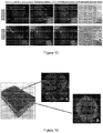
- Figure 3 shows a schematic diagram of one version of a 3D bioprinter of the invention bioprinting mesenchymal stem cell microtissue, and the bioprinted mesenchymal stem cell microtissues.
- FIG. 4 shows that mesenchymal stem cells (MSCs) in the microtissues exhibit high cell viability after bioprinting (A) and injection through a 1.4 millimeter (mm) inside diameter (I.D.) needle (B).
- the scale bar is 100 ⁇ m.
- Figure 5 shows confocal images (A 3D; B section) that revealed the histological architecture of high cell density and ECM.
- the scale bar is 100 ⁇ m.
- Figure 6 shows that the dimension of MSC tissues stabilized after 3 days of culture, which is the time point chosen for implantation.
- Figure 7 shows that an MSC microtissue out grew into the surrounding hydrogel as shown by phase contrast imaging.
- the scale bar is 250 ⁇ m.
- Figure 8 shows MSCs that were labeled with Cellbrite red, green and blue fluorescent dyes and bioprinted into a individual microtissue respectively. The tissue-fusion was observed when they were placed adjacently.
- the scale bar is 500 ⁇ m.
- Figure 9 shows that the printed microtissues could pass through a 1.4 mm I.D. transparent needle.
- the scale bar is 500 ⁇ m.
- MSCs in the microtissues showed high cell viability after injection as shown in Figure 4B .
- Figure 10 shows that cartilage defects (2.0 mm, A-left shows the defect) were generated in the porcine articular cartilage explants.
- Stereo (A-right) and fluorescent microscopic (B) images of the defect show the filling with MSC microtissues.
- Figure 11 shows that two weeks after implantation, the defect is still completely filled in the microtissue filled group (A) comparing with large proportion of void space in the MSCs and hydrogel filled group (B) because of gel shrinkage.
- (C) is the non-treated group.
- Figure 12 shows that two weeks after implantation, the explants were sliced perpendicularly along the line as shown in (A). The sliced tissues were stained with cell viability dyes. B is a fluorescent image of section interface (arrow pointing the bottom of the defect). The green fluorescence indicates high cell viability.
- Example 1 we have successfully developed a new approach in 3D bioprinting to generate MSC microtissues and it shows promise to repair the articular cartilage defects minimally invasively.
- Example 2 describes high throughput 3D bioprinting of tumor micro tissues for drug development and personalized cancer therapy.
- TMTs tumor microtissues
- 3D bioprinting The bioink composed of tumor cells, stromal cells and ECM is loaded into our custom developed 3D bioprinter of the present invention. Micro tumor tissues were directly bioprinted into each well of a 96 or 384 well plate. The viability of the cells in the tissues were analyzed using live/dead staining. Figure 13 shows the schematic diagram of the 3D bioprinter.
- TMTs were cryosectioned or optical sectioned, and analyzed by hematoxylin and eosin (H&E or HE) staining, confocal and multiple-photon microscopy respectively.
- H&E or HE hematoxylin and eosin
- hypoxic micro environment analysis TMT cryosections were stained by using Hypoxyprobe-Green kit which labels hypoxia area with green fluorescence color.
- Invasion assay The TMTs were first printed and the extra bioink without cells were printed around the tumor tissues. Phase contrast or fluorescent imaging were used to analyze tumor invasion into the matrix.
- Angiogenesis assay In order to analyze the pro-angiogenic biomolecules secreted by tumor tissues. Bioprinted microtissue consisted only Human Umbilical Vein Endothelial Cells (HUVECs) and matrix were imbedded in collagen hydrogel and co-cultured with bioprinted TMT and the angiogenesis sprouting was analyzed by phase contrast and fluorescence microscopy.
- HUVECs Human Umbilical Vein Endothelial Cells
- Chemosensitivity test To determine the chemosensitivity of 3D bioprinted TMT and conventional 2D cells, cells and TMTs were plated into each well of a 384-well plate. Drugs were added for 72 hours and live/dead fluorescent was performed. Confocal or multiple-photon microscopy were used to analyze the cell viability in 3D and 2D respectively.
- CAM Chorioallantoic membrane assay
- Figure 16 shows an invasion assay.
- a TMT invaded into the surrounding matrix after being cultured overnight.
- Figure 18 shows endothelial microtissues that were bioprinted and embedded in the collagen matrix. When co-cultured with a bioprinted tumor microtissue (arrow), an endothelial microtissue robust capillary sprouted. The TMT shows higher pro-angiogenic effect than endothelial microtissue alone or with vascular endothelial growth factor stimulation.
- Figure 20 shows tumor micro tissue implantation that was performed using a CAM model.
- (C) the tumor tissue was surgically removed with surrounding membrane.
- Bar 500 ⁇ m
- vascularized human micro liver tissues show significant higher cell density (A) and viability (B) comparing with non-vascularized micro liver tissues (C and D).
- the invention provides a three dimensional microtissue bioprinter and methods for using the three dimensional microtissue bioprinter.
- a computer controlled programmable 3D bioprinter for generating live micro tissues with precisely controlled micro-scale accurate XYZ motion and volumetric nanoliter dispensing capability.
- the invention could be used for personalized cancer therapy.
- Three dimensional bioprinting tumor tissues using cancer cells isolated from individual patients after surgery or biopsy can be used to determine sensitive drug(s) or drug combination(s) for the individual patient, including but not limited to, chemotherapy drugs and radiotherapy-enhancing drugs. Because the 3D tumor tissue closely resembles the in vivo situation, it can more accurately help the oncologists to find the best medication regimen for the patient.
- the invention could be used for cartilage and bone tissue regeneration through minimally invasive surgery.
- the invention could be used for drug metabolism testing for the pharmaceutical industry.
- the invention could be used for drug toxicity screening for the pharmaceutical industry.
Description
- The invention relates to three-dimensional bioprinting, and more particularly to a computer controlled programmable three dimensional (3D) bioprinter generating live microtissues with precisely controlled microscale accurate XYZ motion and volumetric nanoliter dispensing capability.
- Bioprinters were developed to try and meet the challenge of printing three dimensional tissues. Bioprinters fabricate structures via a dropwise printing of cells with a material which serves as the "bio-glue". Bioprinters are limited by slow throughput inherent in the small size of their building materials as well as the vast number of building units that must be deposited. Various techniques and technologies exist for various applications of bioprinting.
- Contact bioprinting is polymer printing without cells, and is used by the 3D Bioplotter available from the Envisiontec company. The polymer printing method only prints a scaffold with a plastics-like polymer.
- Live cell bioprinting uses contact live cell bioprinting in bulk sizes. This technique does not allow microtissue printing as the resultant tissues are a couple of centimeters in size. Contact live cell bioprinting can only perform low throughput printing.
- Non-contact valve based bioprinting techniques provide cell only bioprinting. See, for example, Faulkner-Jones, et al., "Development of a valve-based cell printer for the formation of human embryonic stem cell spheroid aggregates", Biofabrication 5.1 (2013): 015013. Non-contact valve based bioprinting techniques can also provide cell and hydrogel bioprinting. See, for example, Moon, et al., "Layer by layer three-dimensional tissue epitaxy by cell-laden hydrogel droplets", Tissue Engineering Part C: Methods 16.1 (2009): 157-166. Moon, et al. printed the droplets into a larger piece and their system could only generate a structure with cells suspended in the hydrogel without tissue architecture or morphology. Other commercial printers are unable to print tissue with architecture and morphology similar to native tissues.
- Air driven dispensing can provide coaxial gas flow bead generation. This technique uses continuous air flow and continuous dispensing material flow in a coaxial setup, which cannot control the volume of each droplet and cannot dispense a single droplet. This technique ordinarily dispenses thousands of droplets at a time, and in commercial systems, such as those available from Nisco Engineering AG, the material is limited to alginate.
- In cell aggregates-non-real 3D models, cell aggregates are generated by a hanging-drop-method or from a non-adherent cell culture surface. This technique has been used by others trying to mimic 3D tissue and there are commercial products available. However, the aggregates are just piled two dimensional cells without extracellular matrix. For example, it has been shown that the drug resistance mechanism of cell aggregates is the same as two dimensional confluent cells. See, for example, Steadman, Kenneth, et al. "PolyHEMA spheroids are an inadequate model for the drug resistance of the intractable solid tumors." Cell Cycle 7.6 (2008): 818-829. Also, two dimensional cell culture does not resemble the complex biological or pathological nature in vivo. Animal models do not fully resemble human diseases because of species differences.
- From the clinical perspective, minimally invasive approaches are always preferred for joint and many bone surgeries. Others have injected chondrocytes taken from the knee and mesenchymal stem cells in the hopes of repairing tissue defects. However, weak mechanical properties, volume shrinkage and long time in vivo growth make it inapplicable to joint cartilage or bone repair. The document
EP 1 274 508 A2 describes a bioprinter able to deliver small amounts of liquid materials. - Therefore, there exists a need for a technology for printing human tissues in vitro that resemble the nature of human tissues in vivo.
- In one aspect, the present disclosure provides a bioprinter comprising one or more dispensing units. Each dispensing unit may include (i) a syringe including a hollow body and a plunger dimensioned to translate in the body wherein the body has an exit orifice; (ii) an actuator in contact with a proximal end of the plunger; (iii) a controller for moving the actuator; and (iv) a nozzle having a wall defining a fluid path extending from an inlet of the nozzle to an outlet of the nozzle. The inlet of the nozzle is in fluid communication with the exit orifice of the body of the syringe. The nozzle includes a fluid passageway in fluid communication with a source of fluid and the fluid path. The bioprinter can be used in a method of preparing microtissue comprising dispensing a bioink from one or more dispensing units of the bioprinter on a plate. The microtissue may comprise stem cells, bone cells, cartilage cells, liver cells, tumor cells, tumor stromal cells, endothelial cells, and other types of cells. The bioprinter can be used in a method for repairing a bone defect or a cartilage defect comprising dispensing bioink from one or more dispensing units of the bioprinter to create microtissue comprising cartilage cells; and implanting the microtissue in a bone defect or a cartilage defect. The bioprinter can be used in a method for high-throughput screening for drug discovery comprising dispensing bioink from one or more dispensing units of the bioprinter to create a plurality of microtissue samples; and contacting at least a portion of the plurality of microtissue samples with a drug candidate compound. The microtissue samples may comprise tumor cells.
- The controller executes a program received from a computer in the controller to drive the actuator toward the proximal end of the plunger to dispense a bioink from the body of the syringe. The bioprinter may further comprise a temperature controller surrounding the body of the syringe, a temperature controlled plate for receiving a bioink from the outlet of the nozzle, and a humidifier for creating a humidity controlled zone adjacent to the temperature controlled plate. In the bioprinter, fluid from the fluid passageway can separate droplets of dispensed material and may force the droplets of dispensed material to exit the outlet of the nozzle. In the bioprinter, a volume of each droplet may be in a range of 10 nanoliters to 15 microliters. The source of fluid may comprise a controllable valve for supplying fluid. The controllable valve may be controlled by a second controller. The source of fluid in the bioprinter comprises a controllable valve for supplying pulsed fluid, pulsed air, millisecond pulsed air and sub-millisecond pulsed air. In the bioprinter, each dispensing unit may be a non-contact dispensing unit, the nozzle may be integral with the syringe body, and the nozzle may be separate from the syringe body. The outlet of the nozzle can have an inner diameter of 100 microns to 3 millimeters. The bioprinter may comprise a plurality of dispensing units, and each of the dispensing units may be mounted on an XYZ motion system.
- In another aspect, the present disclosure provides a bioprinter comprising one or more dispensing units. Each dispensing unit includes (i) a syringe including a hollow body and a plunger dimensioned to translate in the body, wherein the body has an exit orifice; (ii) an actuator in contact with and moving a proximal end of the plunger; (iii) a controller for controlling the motion of the actuator; and (iv) a nozzle having a wall defining a fluid path extending from an inlet of the nozzle to an outlet of the nozzle. The inlet of the nozzle is in fluid communication with the exit orifice of the body of the syringe. The syringe does not include a valve between the exit orifice of the body of the syringe and proximal end of the plunger. The bioprinter can be used in a method of preparing microtissue comprising dispensing a bioink from one or more dispensing units of the bioprinter on a plate. The microtissue may comprise stem cells, bone cells, cartilage cells, liver cells, tumor cells and other types of cells. The bioprinter can be used in a method for repairing a bone or cartilage defect comprising dispensing bioink from one or more dispensing units of the bioprinter to create microtissue comprising cartilage cells; and implanting the microtissues in a bone or cartilage defect. The bioprinter can be used in a method for high-throughput screening for drug discovery comprising dispensing bioink from one or more dispensing units of the bioprinter to create a plurality of microtissue samples; and contacting at least a portion of the plurality of microtissue samples with a drug library to find candidate compounds. The microtissue samples may comprise tumor cells.
- In the bioprinter, the controller executes a program stored in the controller to drive the actuator toward the proximal end of the plunger to dispense a bioink from the body of the syringe. The bioprinter may further comprise a temperature controller surrounding the body of the syringe, a temperature controlled plate for receiving a bioink from the outlet of the nozzle, and a humidifier for creating a humidity controlled zone adjacent to the temperature controlled plate. The nozzle in the bioprinter may include a fluid passageway in fluid communication with a source of fluid and the fluid path. The fluid from the fluid passageway may separate droplets of dispensed material and may force the droplets of dispensed material to exit the outlet of the nozzle. In the bioprinter, a volume of each droplet may be in a range of 10 nanoliters to 15 microliters. The source of fluid may comprise a controllable value for supplying fluid. The controllable value may be controlled by a second controller. The source of fluid in the bioprinter may comprise a controllable valve for supplying pulsed fluid, pulsed air, millisecond pulsed air and sub-millisecond pulsed air. In the bioprinter, each dispensing unit may be a non-contact dispensing unit, the nozzle may be integral with the syringe body, and the nozzle may be separate from the syringe body. The outlet of the nozzle can have an inner diameter of 100 microns to 3 millimeters. The bioprinter may comprise a plurality of dispensing units, and each of the dispensing units is mounted on an XYZ motion system.
- One version of the bioprinter of the present disclosure is a computer controlled programmable 3D bioprinter generating live micro tissues with precisely controlled micro-scale accurate XYZ motion and volumetric nanoliter dispensing capability.
- One version of the bioprinter of the present disclosure directly prints human cells and extra cellular matrix mixtures onto the surface of cell culture containers, such as culture dishes and micro plates. The printed tissues have the morphology and function of native tissues. The bioprinter works in two modes: (1) high speed printing mode which is used to bioprint micro tissues in large amount for the purpose of tissue regeneration; and (2) precision print mode, which bioprints one, or a specific number of, microtissue(s) into each well of a 96 or 384 well plate for drug screening and personalized therapeutic purposes.
- Our bioprinter has a computer controlled XYZ linear motion system, which controls the position and the movement of the aligned dispensing units (e.g., printing heads). Each dispensing unit dispenses our tissue of interest including cells or matrix or a specified mixture of the two (bio-ink) using the following mechanism. The dispensing unit is composed of: (1) a linear actuator-driven syringe pump controlled by a computer, (2) a dispensing syringe, which holds the bio-ink and dispenses a predetermined nanoliter-volume material through the nozzle each time; and (3) a novel dispensing nozzle. Because an adhesion force exists between the nozzle and the dispensed material, without external force, only larger droplets, about 50 microliters and above, can be generated by gravity force alone. We use a millisecond pulse air dispensing unit to blow the nanoliter level dispensed material away from the syringe nozzle and dispense it onto the surface. The short pulse air flow has very accurate positioning and does not interfere with the already dispensed droplets.
- The printed tissues are in high throughput format for drug screening. The bioprinter rapidly prints live and functional micro tissues for tissue regeneration and modeling. The printed tissues can be composed of: (1) primary type of cells, such as tumor cells, hepatocytes and cardiomyocytes, (2) supporting cells, and (3) extracellular matrix so that they function as native tissues because the micro environment of the tissues are reconstructed. Additionally, we can bioprint stem cells with matrix for cartilage and bone regeneration. We theorize that we can bioprint fibroblasts capable of producing elastin, a molecule that diminishes through life resulting in wrinkles. This could have a profound impact on cosmetic surgery. The ability to print a variety of other tissues is limitless.
- The volumetric non-contact dispensing unit is superior to existing dispensing technology. The volumetric dispensing unit extrudes cells and/or matrix mixture out of the dispensing nozzle at nanoliter resolution; the extrusion is accomplished via a linear actuator. Because the extruded cell-matrix mixture cannot fall off the nozzle by gravity when the volume is at nanoliter level, our dispensing unit uses millisecond air pulses to blow it away from the nozzle to accomplish the dispensing. Other non-contact printer heads, which are valve-based or piezoelectric, rely on timing or pressure to control the volume of dispensing. They need calibration for different viscosity materials while ours does not.
- We are able to print micro tissues with morphology similar to the native tissue. In order to accomplish this, we print the droplets of bioink onto a temperature controlled surface to partially solidify the printed bio-ink during printing and control humidity to keep the printed bioink from drying and to maintain high cell viability. Our precise technology allows us to print tissue systems morphologically comparable to native tissues.
- Our system can use a coaxial setup or a non-coaxial setup for delivery of pulsed air. A non-coaxial setup has better position control of the dispensed material.
- Our results show that our printed tumor micro tissues, with the same components as native tumor tissue, are much more drug resistant to chemotherapy drugs than the cell aggregates. Additionally, there are many types of cells that do not aggregate and are not amenable to conventional cell aggregating techniques. We can still print these non-aggregating tissues using our bioprinter/technique. This represents a much more realistic testing scenario.
- Our bioprinted microtissue is predeveloped and mechanically enhanced in vitro. Once injected in vivo, the tissues self-assemble into large tissue amalgamations which can repair the defects.
- Our bioprinted microtissue fills a need in predicting drug effectiveness or other medication on the human organism.
- These and other features, aspects, and advantages of the present invention will become better understood upon consideration of the following detailed description, drawings, and appended claims.
-
-
Figure 1 is a perspective view of a bioprinter according to the invention with a partially exploded section showing the dispensing unit of the bioprinter. -
Figure 2 is a partial side view, with the dispensing unit in cross-section, of the bioprinter ofFigure 1 . -
Figure 2A is a perspective view of the XYZ motion system of the bioprinter ofFigures 1 and 2 . -
Figure 3 shows a schematic diagram of one version of a 3D bioprinter of the invention bioprinting mesenchymal stem cell microtissue, and the bioprinted mesenchymal stem cell microtissues. -
Figure 4 shows that mesenchymal stem cells (MSCs) in the microtissues exhibit high cell viability after bioprinting (A) and injection through a 1.4 millimeter (mm) inside diameter (I.D.) needle (B). The scale bar is 100 µm. -
Figure 5 shows confocal images (A 3D; B section) that revealed the histological architecture of high cell density and extracellular matrix (ECM). The scale bar is 100 µm. -
Figure 6 shows that the dimension of MSC tissues stabilized after 3 days of culture, which is the time point chosen for implantation. -
Figure 7 shows that MSC microtissues out grew into the surrounding hydrogel as shown by phase contrast imaging. The scale bar is 250 µm. -
Figure 8 shows MSCs that were labeled with Cellbrite red, green and blue fluorescent dyes and bioprinted into a individual microtissue respectively. The tissue-fusion was observed when they were placed adjacently. The scale bar is 500 µm. -
Figure 9 shows that the printed microtissues could pass through a 1.4 mm I.D. transparent needle. The scale bar is 500µm. MSCs in the microtissues showed high cell viability after injection as shown inFigure 4B . -
Figure 10 shows that cartilage defects (2.0 mm, A-left shows the defect) were generated in the porcine articular cartilage explants. Stereo (A-right) and fluorescent microscopic (B) images of the defect show the filling with MSC microtissues. -
Figure 11 shows that two weeks after implantation, the defect is still completely filled in the microtissue filled group (A) comparing with large proportion of void space in the MSCs and hydrogel filled group (B) because of gel shrinkage. (C) is the non-treated group. -
Figure 12 shows that two weeks after implantation, the explants were sliced perpendicularly along the line as shown in (A). The sliced tissues were stained with cell viability dyes. B is a fluorescent image of section interface (arrow pointing the bottom of the defect). The green fluorescence indicates high cell viability. -
Figure 13 shows a schematic diagram of a 3D bioprinter of the invention. -
Figure 14 shows in (A), H&E staining of a bioprinted tumor microtissue (TMT), which has similar morphology to the native tumor tissues. (Bar= 100µm); in (B), 3D volume reconstructed image of a bioprinted TMT, which was imaged by confocal microscopy; and in (C), a representative image of a micro tumor tissue in a well of a 384 well plate, green staining indicates live cells. (Bar= 100µm) -
Figure 15 shows representative images of a TMT in (A), composed of human endothelial cells in (B), human mesenchymal stem cells in (C) and human cancer cells in (D). (Bar = 100µm). -
Figure 16 shows an invasion assay. A TMT invaded into the surrounding matrix after being cultured overnight. The red area (center) in C shows the original location of the TMT at day 1. (Bar = 100µm) -
Figure 17 shows the TMT sections that were stained with a Hypoxyprobe - Green kit which can stain a hypoxia area into a fluorescent green color. A large number of hypoxic cells were observed within the core of the bioprinted micro tumor tissue. (Bar = 100µm) -
Figure 18 shows endothelial microtissues that were bioprinted and embedded in the collagen matrix. When co-cultured with a bioprinted tumor microtissue (arrow), a endothelial microtissue robust capillary sprouted. The TMT shows higher pro-angiogenic effect than endothelial microtissue alone or with vascular endothelial growth factor stimulation. -
Figure 19 shows a chemosensitivity analysis using two dimensional tumor cells (A) and TMT (B) in a 384-well plate. After 72 hours of drug treatment, live/dead cell staining with Hoechst dye and propidium iodide (PI) were performed. With confocal or multiple-photon microscopy, optical sections were used for cell viability analysis and to determine the IC50. (Bar = 50µm) -
Figure 20 shows tumor micro tissue implantation that was performed using a CAM model. The stereo microscopic views at the times of (A) implantation (B) 8 days after implantation. In (C), the tumor tissue was surgically removed with surrounding membrane. (Bar = 500µm) -
Figure 21 shows vascularized human micro liver tissues that were bioprinted with HepG2 human liver cells and human endothelial cells. The vascularized micro liver tissues show significant higher cell density (A: H&E staining) and viability (B: live-dead staining, blue indicating live cells and purple indicating dead cells) comparing with non-vascularized micro liver tissues (C : H&E staining. D: live-dead staining). - Like reference numerals will be used to refer to like parts from Figure to Figure in the following description of the drawings.
- Referring now to
Figures 1 and 2 , there is shown one non-limiting example embodiment of abioprinter 10 according to the invention. Thebioprinter 10 may include a plurality of dispensingunits 12. For ease of illustration and description, one dispensingunit 12 is shown inFigure 1 . The dispensingunit 12 includes asyringe 14, anozzle 25, anactuation mechanism 36, and a temperature controller 43 (shown in dashed lines inFig. 1 ). - The
syringe 14 has abody 15 defining a hollowinterior space 16 of thesyringe 14. Typically, thebody 15 comprises an opaque, translucent, or transparent polymeric material, such as polypropylene. Aplunger 17 having a disk-shapedproximal end 18 and a disk-shapeddistal end 19 is positioned in theinterior space 16 of thesyringe 14 for movement toward and away from anexit orifice 20 defined by a dispensingtip 21 of thesyringe 14. Abioink 22 is contained in theinterior space 16 of thesyringe 14. No valve is required between theexit orifice 20 of thebody 15 of thesyringe 14 and thedistal end 19 of the plunger. - The
nozzle 25 has aside wall 26, aninlet 27, and anoutlet 28, which may have an inside diameter of 100 microns to 3 millimeters. Theside wall 26 defines afluid path 29 in thenozzle 25 between theinlet 27 and theoutlet 28. Thenozzle 25 includes afluid port 31 that defines afluid passageway 32 in fluid communication with thefluid path 29 in thenozzle 25. A fluid conduit 33 places thefluid passageway 32 of thefluid port 31 in fluid communication with a source offluid 34. A controllable valve can be placed between the fluid conduit 33 and the source offluid 34 for supplying fluid to thefluid passageway 32 of thefluid port 31. The controllable valve can be controlled by a controller that opens and closes the controllable valve to deliver pulsed fluid (e.g., air) from the source offluid 34 to thefluid passageway 32 of thefluid port 31. In the version of the dispensingunit 12 shown, thenozzle 25 is separate from thebody 15 of thesyringe 14. However, thenozzle 25 can be integral with thebody 15 of thesyringe 14. - The
actuation mechanism 36 of the dispensingunit 12 includes acontroller 37 and anactuator 38 having aleadscrew 39 and a disk shapeddistal end section 41. Thecontroller 37 may be linked to theactuator 38 through anelectrical cable 42. When thesyringe 14 is installed in the dispensingunit 12, thedistal end section 41 of theactuator 38 is placed in contact with theproximal end 18 of theplunger 17. Theactuator 38 is a linear actuator. Theactuator 38 is a step motor based device. Through theleadscrew 39 and rotating locker mechanism inside, theactuator 38 converts the rotation of a step motor inside theactuator 38 into the linear motion of theleadscrew 39. The distance which thedistal end 41 travels depends on the degree of step motor rotation. The degree of rotation is controlled by thecontroller 37 which receives the command sent from a computer program. Theleadscrew 39 moves toward theproximal end 18 of theplunger 17 to dispense the bioink 22 from thebody 15 of thesyringe 14. - The
temperature controller 43 of the dispensingunit 12 includes ahousing 44 that surroundstemperature controlling elements 45, such as Peltier cooling-and-heating elements. Thetemperature controller 43 provides a temperature controlled enclosure to surround thesyringe 14 and dispensingnozzle 25. One purpose of the temperature controlled enclosure is to control the temperature of the bioink 22 (e.g., cells and/or matrix) at a desired level, which is cold most of time and may be warmed occasionally according to different applications. - Still referring to
Figures 1 and 2 , thebioprinter 10 includes atemperature control plate 50 for receivingbioink 22 that is dispensed from the dispensingunit 12. Thetemperature control plate 50 may comprise resistive heating elements or Peltier cooling-and-heating elements. that receive electricity via anelectrical lead 51. Thebioprinter 10 also includes ahumidifier 58 with atubular flow director 59. Thehumidifier 58 creates a humidity controlledzone 61 adjacent thetemperature control plate 50.Droplets 66 of thebioink 22exit outlet 28 of thenozzle 25 and createmicrotissue 68 on thetemperature control plate 50. - Looking at
Figure 2A , thebioprinter 10 includes an XYZ motion system 80 having a support X, a support Y1, a support Y2, and housings Z1, Z2, Z3, which each house a dispensingunit 12 as shown inFigure 1 . Adrive control mechanism 85 controls motion of support Y1, and support Y2 towards and away from each other in directions Ay and By shown inFigure 2 . Adrive control mechanism 86 controls motion of support X in directions Ax and Bx shown inFigure 2 . Adrive control mechanisms Figure 2 . Thedrive control mechanisms unit 12 is mounted to a Z-axis. - In
Figure 2A , three Z axis dispensing unit housings Z1, Z2, Z3 are shown as a non-limiting representative number. However, there is no limitation on the number of dispensing units; it depends on how many components are needed to print for a specific microtissue. For example, when using three dispensing units, (i) three dispensing units could each include the same bioink, (ii) two dispensing units could include the same bioink and the other dispensing unit could include a different bioink, or (iii) three dispensing units could each include a different bioink. - Having described the components of the
bioprinter 10, operation of thebioprinter 10 can be explained further. A microplate including an array of wells (e.g., 384, 1536, or 3456 wells) can be placed on thetemperature control plate 50 for receivingbioink 22 that is dispensed from the dispensingunit 12. Alternatively, other cell culture containers without an array of wells (such as a Petri dish or single well plate) on thetemperature control plate 50 can directly receivebioink 22 that is dispensed from the dispensingunit 12. -
Syringes 14 filled with the same or different bioinks are installed in each dispensingunit 12, and thecontroller 37 is programmed for a dispensing sequence. Thecontroller 37 places thedistal end section 41 of each actuator 38 in contact with theproximal end 18 of the associatedplunger 17. The XYZ motion system 80 moves the dispensing units over selected wells (or selected locations on the temperature control plate 50). As the controller drives each actuator 38 toward theplate 50,bioink 22 flows into thefluid path 29 in thenozzle 25. The controllable valve then opens and closes to deliver pulsed fluid (e.g., air) from the source offluid 34 to thefluid passageway 32 of thefluid port 31. The pulsed fluid createsseparate droplets 66 from the flow of bioink in thefluid path 29 in thenozzle 25. A volume of each droplet can be in a range of 10 nanoliters to 15 microliters. Thedroplets 66 are repeatedly placed on the plate 50 (or in the wells of the microplate) to create the microtissue samples 68 (seeFig. 2 ). Thebioprinter 10 uses volumetric based dispensing, which means the volume of dispensing is linear to the distance that theplunger 17 moves. - The invention is further illustrated in the following Examples which are presented for purposes of illustration and not of limitation.
- Example 1 describes the development of injectable mesenchymal stem cells (MSCs) microtissues for repairing cartilage defects using 3D bioprinting. This is a representative project for our high speed bioprinting in which we bioprint micro-cartilage and bone tissues using human bone marrow mesenchymal stem cells (MSCs). We have successfully bioprinted micro bone tissue and MSC-incorporated-tissue for cartilage and bone regeneration. Our bioprinted micro-tissue is predeveloped and mechanically enhanced in vitro. Once injected in vivo, the tissues self-assemble into large tissue amalgamations which can repair the defects.
- Articular cartilage exhibits poor intrinsic capacity for repair, and tissue engineering is a new approach for articular cartilage repair. Bone marrow mesenchymal stem cells (MSCs) and bulk hydrogel have been used to repair the cartilage defects in open surgery. As a minimally invasive approach is always preferred for joint surgery, injectable tissue engineered cartilage would be an ideal solution to repair cartilage defects. However, volume shrinkage and poor mechanical properties of hydrogel, which results in void space in the implantation, limit the application of a MSCs-hydrogel injection. In this example, we aimed to develop volume stabilized MSC microtissues using 3D bioprinting, and repair the defect in articular cartilage through the self-assembly of the micro tissues.
-
- 1. 3D bioprinting: The microtissues, comprising human MSCs and bioink composed of hydrogels in the pre-optimized combination, were directly bioprinted using our custom developed 3D bioprinter of the present invention (see
Fig. 3 ). - 2. Cell viability: Live/dead cell viability assay in MSC microtissues was performed after bioprinting.
- 3. Morphology: Morphology of the microtissue was studied by HE staining and confocal microscopy.
- 4. Dimension alteration: Diameters of the microtissues were imaged by microscopically at a series of time points to analyze the volume alteration.
- 5. Single tissue 3D out growth: The microtissues were embedded in the hydrogel within a 96-well plate to observe tissue outgrowth under an inverted microscope.
- 6. Multiple tissue fusion/assembly: MSCs were labeled with Cellbrite (red, green and blue respectively) and several microtissues were placed on the ultra-low attachment surface to observe tissue fusion at different time points.
- 7. Injectability: The bioprinted microtissues suspended in medium were pushed through a 1.4 mm I.D. needle, and cell viability was analyzed by live/dead staining.
- 8. Cartilage defect repairing in a cartilage explants culture model: Defects, 2 mm in diameter, were made in the porcine articular cartilage explants. The defects were filled with MSC microtissues to evaluate integration outcome. MSC hydrogel were used as the control. Also, live/dead staining was performed to study cell viability after 2 weeks cultivation.
-
Figure 3 shows a schematic diagram of one version of a 3D bioprinter of the invention bioprinting mesenchymal stem cell microtissue, and the bioprinted mesenchymal stem cell microtissues. -
Figure 4 shows that mesenchymal stem cells (MSCs) in the microtissues exhibit high cell viability after bioprinting (A) and injection through a 1.4 millimeter (mm) inside diameter (I.D.) needle (B). The scale bar is 100 µm. -
Figure 5 shows confocal images (A 3D; B section) that revealed the histological architecture of high cell density and ECM. The scale bar is 100 µm. -
Figure 6 shows that the dimension of MSC tissues stabilized after 3 days of culture, which is the time point chosen for implantation. -
Figure 7 shows that an MSC microtissue out grew into the surrounding hydrogel as shown by phase contrast imaging. The scale bar is 250 µm. -
Figure 8 shows MSCs that were labeled with Cellbrite red, green and blue fluorescent dyes and bioprinted into a individual microtissue respectively. The tissue-fusion was observed when they were placed adjacently. The scale bar is 500 µm. -
Figure 9 shows that the printed microtissues could pass through a 1.4 mm I.D. transparent needle. The scale bar is 500µm. MSCs in the microtissues showed high cell viability after injection as shown inFigure 4B . -
Figure 10 shows that cartilage defects (2.0 mm, A-left shows the defect) were generated in the porcine articular cartilage explants. Stereo (A-right) and fluorescent microscopic (B) images of the defect show the filling with MSC microtissues. -
Figure 11 shows that two weeks after implantation, the defect is still completely filled in the microtissue filled group (A) comparing with large proportion of void space in the MSCs and hydrogel filled group (B) because of gel shrinkage. (C) is the non-treated group. -
Figure 12 shows that two weeks after implantation, the explants were sliced perpendicularly along the line as shown in (A). The sliced tissues were stained with cell viability dyes. B is a fluorescent image of section interface (arrow pointing the bottom of the defect). The green fluorescence indicates high cell viability. - In Example 1, we have successfully developed a new approach in 3D bioprinting to generate MSC microtissues and it shows promise to repair the articular cartilage defects minimally invasively.
- Example 2 describes high throughput 3D bioprinting of tumor micro tissues for drug development and personalized cancer therapy.
- Cancer caused about 25% of all deaths in the United States in 2014. In vitro anti-cancer drug screening is widely used in the pharmaceutical industry and chemosensitivity test for patients. However, only 2D assays and simple 3D culture models were used previously. But these models do not resemble the native tumor microenvironment, or yield inaccurate prediction of drug sensitivity. In this example, we report a novel 3D bioprinted model of tumor microtissues (TMTs), which resemble the native tumor characteristics, for high throughput screening. We characterized the 3D bioprinted tumors in various of aspects.
- 3D bioprinting: The bioink composed of tumor cells, stromal cells and ECM is loaded into our custom developed 3D bioprinter of the present invention. Micro tumor tissues were directly bioprinted into each well of a 96 or 384 well plate. The viability of the cells in the tissues were analyzed using live/dead staining.
Figure 13 shows the schematic diagram of the 3D bioprinter. - Morphologic characterization: The TMTs were cryosectioned or optical sectioned, and analyzed by hematoxylin and eosin (H&E or HE) staining, confocal and multiple-photon microscopy respectively.
- Hypoxic micro environment analysis: TMT cryosections were stained by using Hypoxyprobe-Green kit which labels hypoxia area with green fluorescence color.
- Invasion assay: The TMTs were first printed and the extra bioink without cells were printed around the tumor tissues. Phase contrast or fluorescent imaging were used to analyze tumor invasion into the matrix.
- Angiogenesis assay: In order to analyze the pro-angiogenic biomolecules secreted by tumor tissues. Bioprinted microtissue consisted only Human Umbilical Vein Endothelial Cells (HUVECs) and matrix were imbedded in collagen hydrogel and co-cultured with bioprinted TMT and the angiogenesis sprouting was analyzed by phase contrast and fluorescence microscopy.
- Chemosensitivity test: To determine the chemosensitivity of 3D bioprinted TMT and conventional 2D cells, cells and TMTs were plated into each well of a 384-well plate. Drugs were added for 72 hours and live/dead fluorescent was performed. Confocal or multiple-photon microscopy were used to analyze the cell viability in 3D and 2D respectively.
- In vivo implantation: Chorioallantoic membrane assay (CAM) was used to evaluate the tumorigenicity in vivo. TMTs were implanted on the top of the growing CAMs on 8th day of development. On the 16th day, each egg was imaged using stereo microscope. The tumors were surgically removed with surrounding membrane and fixed in 4% paraformaldehyde for further histological analysis.
-
Figure 14 shows in (A), H&E staining of a bioprinted tumor microtissue (TMT), which has similar morphology to the native tumor tissues. (Bar= 100µm); in (B), 3D volume reconstructed image of a bioprinted TMT, which was imaged by confocal microscopy; and in (C), a representative image of a micro tumor tissue in a well of a 384 well plate, green staining indicates live cells. (Bar= 100µm) -
Figure 15 shows representative images of a TMT in (A), composed of human endothelial cells in (B), human mesenchymal stem cells in (C) and human cancer cells in (D). (Bar = 100µm). -
Figure 16 shows an invasion assay. A TMT invaded into the surrounding matrix after being cultured overnight. The red area (center) in C shows the original location of the TMT at day 1. (Bar = 100µm) -
Figure 17 shows the TMT sections that were stained with a Hypoxyprobe - Green kit which can stain a hypoxia area into a fluorescent green color. A large number of hypoxic cells were observed within the core of the bioprinted micro tumor tissue. (Bar = 100µm) -
Figure 18 shows endothelial microtissues that were bioprinted and embedded in the collagen matrix. When co-cultured with a bioprinted tumor microtissue (arrow), an endothelial microtissue robust capillary sprouted. The TMT shows higher pro-angiogenic effect than endothelial microtissue alone or with vascular endothelial growth factor stimulation. -
Figure 19 shows a chemosensitivity analysis using two dimensional tumor cells (A) and TMT (B) in a 384-well plate. After 72 hours of drug treatment, live/dead cell staining with Hoechst dye and propidium iodide (PI) were performed. With confocal or multiple-photon microscopy, optical sections were used for cell viability analysis and to determine the IC50. (Bar = 50µm) -
Figure 20 shows tumor micro tissue implantation that was performed using a CAM model. The stereo microscopic views at the times of (A) implantation (B) 8 days after implantation. In (C), the tumor tissue was surgically removed with surrounding membrane. (Bar = 500µm) - We have successfully developed a high throughput 3D bioprinting system to generate tumor micro tissues in vitro, which resemble many characteristics of the native tumor tissues. The system has therefore demonstrated as a powerful tool for screening anti-cancer drugs and selecting the sensitive drugs for personalized cancer therapy.
- We 3D bioprinted liver tissues. Specifically, we have successfully bioprinted vascularized human micro liver tissues using HepG2 human liver cells and human endothelial cells. As shown in
Fig. 21 , the vascularized micro liver tissues show significant higher cell density (A) and viability (B) comparing with non-vascularized micro liver tissues (C and D). - Thus, the invention provides a three dimensional microtissue bioprinter and methods for using the three dimensional microtissue bioprinter. We have disclosed a computer controlled programmable 3D bioprinter for generating live micro tissues with precisely controlled micro-scale accurate XYZ motion and volumetric nanoliter dispensing capability. We have printed many types of tissue with many different types of cells including pluripotent stem cells, bone marrow mesechymal stem cells, osteoblasts, fibroblast, human endothelial cells, liver cells, and many different tumor cells.
- We have bioprinted micro tumor tissues for high throughput drug screening and therapeutic purposes. We have characterized many aspects of the printed tumor tissues including morphology, function, biomarker, micro-environment, 3D structure, and invasion and drug sensitivities. As we have experience in tumor bioprinting, we envision successful micro heart and liver tissue printing which requires the same technical procedures with different cells. We 3D bioprinted liver tissues.
- We have performed anti-tumor drug screening with 3D bioprinted tumor tissues as described above. This is a desirable service for the pharmaceutical industry to develop new anti-cancer drugs, including but not limited to, chemotherapy drugs, and radiotherapy sensitivity enhancing drugs. The advantage is that our system can assist in development significantly more quickly and at markedly lower development costs (no animal studies). The 3D nature of the bioprinted tissues should also allow for more accurate assessment compared to currently employed 2D cultured cell screening also saving money and time.
- The invention could be used for personalized cancer therapy. Three dimensional bioprinting tumor tissues using cancer cells isolated from individual patients after surgery or biopsy can be used to determine sensitive drug(s) or drug combination(s) for the individual patient, including but not limited to, chemotherapy drugs and radiotherapy-enhancing drugs. Because the 3D tumor tissue closely resembles the in vivo situation, it can more accurately help the oncologists to find the best medication regimen for the patient.
- The invention could be used for cartilage and bone tissue regeneration through minimally invasive surgery.
- The invention could be used for drug metabolism testing for the pharmaceutical industry. We can utilize our 3D bioprinted micro liver tissues to test drugs under development for their metabolism profiles in high throughput.
- The invention could be used for drug toxicity screening for the pharmaceutical industry. We can utilize our 3D bioprinted micro liver and heart tissues to screen for toxicity of candidate drugs for the pharmaceutical industry.
- Although the present invention has been described in detail with reference to certain embodiments, one skilled in the art will appreciate that the present invention can be practiced by other than the described embodiments, which have been presented for purposes of illustration and not of limitation. Therefore, the scope of the appended claims should not be limited to the embodiments contained herein.
Claims (14)
- A bioprinter (10) comprising:a source of fluid, and one or more dispensing units (12), each dispensing unit including(i) a syringe (14) including a hollow body (15) and a plunger (17) dimensioned to translate in the body, the body having an exit orifice (20);(ii) an actuator (38) in contact with a proximal end of the plunger;(iii) a controller (37) for controlling linear motion of the actuator, wherein the controller is configured to drive the actuator toward the proximal end of the plunger to dispense a bioink from the body of the syringe; and(iv) a nozzle (25) having a wall (26) defining a fluid path (29) extending from an inlet (27) of the nozzle to an outlet (28) of the nozzle, the inlet of the nozzle being in fluid communication with the exit orifice of the body of the syringe, wherein as the controller drives the actuator toward the proximal end of the plunger bioink flows into the fluid path,wherein the nozzle includes a fluid passageway (32) in fluid communication with the source of fluid (34) and the fluid path, characterised in that, the controller is further configured to controla controllable valve to deliver pulsed fluid from the source of fluid to the fluid passageway to create separate droplets (66) from the flow of bioink in the fluid path in the nozzle.
- The bioprinter of claim 1 wherein:
the controller executes a program received from a computer in the controller to drive the actuator toward the proximal end of the plunger to dispense a bioink from the body of the syringe. - A method of preparing microtissue, the method comprising:(a) dispensing a bioink from one or more dispensing units of the bioprinter of claim 1 on a plate.
- The method of claim 3 wherein:
the microtissue comprises tumor cells, tumor stromal cells and endothelial cells. - A method for repairing a bone defect or a cartilage defect, the method comprising:(a) dispensing bioink from one or more dispensing units of the bioprinter of claim 1 to create microtissue comprising cartilage cells; and(b) implanting the microtissue in the bone defect or the cartilage defect.
- A method of high-throughput screening for drug discovery, the method comprising:(a) dispensing bioink from one or more dispensing units of the bioprinter of claim 1 to create a plurality of microtissue samples; and(b) contacting at least a portion of the plurality of microtissue samples with a drug candidate compound.
- The bioprinter of claim 1 wherein:
the syringe does not include a valve between the exit orifice of the body of the syringe and a distal end of the plunger. - The bioprinter of claim 7 wherein:
the controller executes a program stored in the controller to drive the actuator toward the proximal end of the plunger to dispense a bioink from the body of the syringe. - The bioprinter of claim 1 or claim 7 further comprising:
a temperature controller surrounding the body of the syringe. - The bioprinter of claim 1 or claim 7 further comprising:
a temperature controlled plate for receiving a bioink from the outlet of the nozzle. - The bioprinter of claim 10 further comprising:
a humidifier for creating a humidity controlled zone adjacent to the temperature controlled plate. - The bioprinter of claim 1 or claim 7 wherein:
the controllable valve supplies millisecond pulsed air. - The bioprinter of claim 1 or claim 7 wherein:
the bioprinter comprises a plurality of the dispensing units. - The bioprinter of claim 1 or claim 7 wherein:
the bioprinter uses a non-coaxial setup for delivery of pulsed air.
Applications Claiming Priority (2)
| Application Number | Priority Date | Filing Date | Title |
|---|---|---|---|
| US201562214551P | 2015-09-04 | 2015-09-04 | |
| PCT/US2016/050167 WO2017040975A1 (en) | 2015-09-04 | 2016-09-02 | Three dimensional microtissue bioprinter |
Publications (3)
| Publication Number | Publication Date |
|---|---|
| EP3344400A1 EP3344400A1 (en) | 2018-07-11 |
| EP3344400A4 EP3344400A4 (en) | 2019-06-12 |
| EP3344400B1 true EP3344400B1 (en) | 2022-07-20 |
Family
ID=58188478
Family Applications (1)
| Application Number | Title | Priority Date | Filing Date |
|---|---|---|---|
| EP16843097.3A Active EP3344400B1 (en) | 2015-09-04 | 2016-09-02 | Three dimensional microtissue bioprinter |
Country Status (5)
| Country | Link |
|---|---|
| US (2) | US11400183B2 (en) |
| EP (1) | EP3344400B1 (en) |
| JP (1) | JP2018529334A (en) |
| CN (1) | CN108602089B (en) |
| WO (1) | WO2017040975A1 (en) |
Families Citing this family (22)
| Publication number | Priority date | Publication date | Assignee | Title |
|---|---|---|---|---|
| JP6502857B2 (en) | 2013-01-14 | 2019-04-17 | スクリップス ヘルス | Tissue array printing |
| AU2016340154A1 (en) * | 2015-10-15 | 2018-04-26 | The Regents Of The University Of California | Systems, apparatus and methods for cryogenic 3D printing |
| US11220060B2 (en) | 2015-12-30 | 2022-01-11 | Revotek Co., Ltd | Bioprinter temperature control system and bioprinter |
| EP3463169B1 (en) | 2016-05-26 | 2023-07-19 | Scripps Health | Systems to repair tissue defects |
| US20180051113A1 (en) * | 2016-08-22 | 2018-02-22 | Board Of Regents, The University Of Texas System | Melt-processable thermoset polymers, method of synthesis thereof and use in fused filament fabrication printing |
| US20180290360A1 (en) * | 2017-04-06 | 2018-10-11 | Mold-Masters (2007) Limited | Liquid injection molding apparatus |
| WO2018218060A2 (en) * | 2017-05-25 | 2018-11-29 | Tdbt Ip Inc. | Aseptic printer system including dual-arm mechanism |
| US10570362B2 (en) * | 2017-07-12 | 2020-02-25 | Deka Products Limited Partnership | System and method for transferring tissue |
| CN108891026B (en) * | 2018-08-03 | 2021-03-02 | 广州迈普再生医学科技股份有限公司 | Piston extrusion type spray head of 3D printer |
| US10434713B1 (en) * | 2018-05-15 | 2019-10-08 | Taiyuan University Of Technology | Printhead device for 3D bio-printer |
| US20210269776A1 (en) * | 2018-06-28 | 2021-09-02 | Cedars-Sinai Medical Center | Compact mechanical syringe extruder for 3d bioprinting of cell laden gels |
| CN108819219A (en) * | 2018-09-07 | 2018-11-16 | 上海黑焰医疗科技有限公司 | A kind of hand-held 3D biomaterial extruder |
| JP2022520583A (en) * | 2019-02-15 | 2022-03-31 | セリンク エービー | Systems and methods for controlled discharge of temperature sensitive fluids in liquid treatment and discharge systems |
| GB201902862D0 (en) * | 2019-03-04 | 2019-04-17 | Univ Dublin | A print head and insert for use with a three-dimensional bioprinter |
| WO2021090089A1 (en) * | 2019-11-05 | 2021-05-14 | Io Tech Group Ltd. | Systems for material deposition |
| WO2021178928A2 (en) * | 2020-03-05 | 2021-09-10 | Meatech 3D, Ltd. | Bioprinter print head |
| GB2587251B (en) * | 2020-03-24 | 2021-12-29 | Rem3Dy Health Ltd | 3D printer |
| CN112140530B (en) * | 2020-09-16 | 2022-04-01 | 清源泰硕(北京)生物医疗科技有限公司 | Multi-module serial biological 3D printing device |
| KR102459226B1 (en) | 2021-03-30 | 2022-10-27 | 한국기계연구원 | An apparatus for manufacturing a well plate using micro-scale additive processing and dispensing a solution, and a method for manufacturing a well plate and dispensing a solution using the same |
| WO2023247801A1 (en) * | 2022-06-24 | 2023-12-28 | Katholieke Universiteit Leuven | Printing of cell aggregates |
| CN114940971B (en) * | 2022-06-24 | 2024-03-15 | 中山大学 | Construction method of high-activity cartilage tissue based on Faraday wave |
| WO2024006369A1 (en) * | 2022-06-30 | 2024-01-04 | Illumina, Inc. | Non-contact dispensers and related systems and methods |
Family Cites Families (21)
| Publication number | Priority date | Publication date | Assignee | Title |
|---|---|---|---|---|
| WO2001074490A2 (en) | 2000-04-03 | 2001-10-11 | Ecole Polytechnique Federale De Lausanne (Epfl) | A device for dispensing accurately-controlled small doses of liquid |
| WO2002040634A2 (en) | 2000-11-14 | 2002-05-23 | Genetag Technology, Inc. | Expression miniarrays and uses thereof |
| AU2002324775A1 (en) | 2001-08-23 | 2003-03-10 | Sciperio, Inc. | Architecture tool and methods of use |
| GB2393234A (en) | 2002-07-11 | 2004-03-24 | Willett Int Ltd | Solenoid valve and the use thereof in a drop on demand ink jet printer |
| US7051654B2 (en) | 2003-05-30 | 2006-05-30 | Clemson University | Ink-jet printing of viable cells |
| US8241905B2 (en) | 2004-02-24 | 2012-08-14 | The Curators Of The University Of Missouri | Self-assembling cell aggregates and methods of making engineered tissue using the same |
| WO2006005923A1 (en) | 2004-07-08 | 2006-01-19 | Norgren Limited | Liquid dispensing system |
| US7939003B2 (en) | 2004-08-11 | 2011-05-10 | Cornell Research Foundation, Inc. | Modular fabrication systems and methods |
| WO2007124481A2 (en) | 2006-04-21 | 2007-11-01 | Drexel University | Bioprinting three-dimensional structures onto microscale tissue analog devices for pharmacokinetic study and other uses |
| US8287959B2 (en) * | 2007-04-19 | 2012-10-16 | Stratasys, Inc. | Syringe tip assembly and layered deposition systems utilizing the same |
| ES2671594T3 (en) | 2010-03-04 | 2018-06-07 | INSERM (Institut National de la Santé et de la Recherche Médicale) | Bioprinting station, assembly comprising said bioprinting station and bioprinting method |
| US20120089238A1 (en) * | 2010-10-06 | 2012-04-12 | Hyun-Wook Kang | Integrated organ and tissue printing methods, system and apparatus |
| DE102011121956A1 (en) * | 2011-12-23 | 2013-06-27 | Arburg Gmbh + Co. Kg | Control method for characteristic map determination |
| JP6065386B2 (en) | 2012-03-05 | 2017-01-25 | セイコーエプソン株式会社 | Mist collection device |
| US20150037445A1 (en) | 2013-07-31 | 2015-02-05 | Organovo, Inc. | Automated devices, systems, and methods for the fabrication of tissue |
| US11903612B2 (en) * | 2013-11-04 | 2024-02-20 | University Of Iowa Research Foundation | Bioprinter and methods of using same |
| WO2015107333A1 (en) | 2014-01-14 | 2015-07-23 | King's College London | 3d printing of facial prostheses |
| US9579829B2 (en) * | 2014-06-02 | 2017-02-28 | Vadient Optics, Llc | Method for manufacturing an optical element |
| CN104403923B (en) * | 2014-11-11 | 2016-11-23 | 南京卡迪睿伯生物技术有限公司 | Three-dimensional tissue's organ culture model and high throughput automated stereo-picture analysis platform thereof and application thereof |
| US20160325498A1 (en) * | 2015-05-04 | 2016-11-10 | Daniel Gelbart | 3D Printer Based on a Staggered Nozzle Array |
| US9968437B2 (en) * | 2015-06-22 | 2018-05-15 | Bao Tran | 3D printer |
-
2016
- 2016-09-02 CN CN201680063270.4A patent/CN108602089B/en active Active
- 2016-09-02 US US15/757,461 patent/US11400183B2/en active Active
- 2016-09-02 JP JP2018512170A patent/JP2018529334A/en active Pending
- 2016-09-02 WO PCT/US2016/050167 patent/WO2017040975A1/en active Application Filing
- 2016-09-02 EP EP16843097.3A patent/EP3344400B1/en active Active
-
2022
- 2022-06-29 US US17/852,663 patent/US20220323649A1/en active Pending
Also Published As
| Publication number | Publication date |
|---|---|
| JP2018529334A (en) | 2018-10-11 |
| WO2017040975A1 (en) | 2017-03-09 |
| CN108602089B (en) | 2022-11-04 |
| US20220323649A1 (en) | 2022-10-13 |
| CN108602089A (en) | 2018-09-28 |
| EP3344400A1 (en) | 2018-07-11 |
| US11400183B2 (en) | 2022-08-02 |
| EP3344400A4 (en) | 2019-06-12 |
| US20180243478A1 (en) | 2018-08-30 |
Similar Documents
| Publication | Publication Date | Title |
|---|---|---|
| US20220323649A1 (en) | Three dimensional microtissue bioprinter | |
| Ma et al. | 3D bioprinting of functional tissue models for personalized drug screening and in vitro disease modeling | |
| Radhakrishnan et al. | Organotypic cancer tissue models for drug screening: 3D constructs, bioprinting and microfluidic chips | |
| US20200140808A1 (en) | Self-assembling cell aggregates and methods of making engineered tissue using the same | |
| EP2526978B1 (en) | Device and method of generating in vitro blood vessels | |
| Banerjee et al. | Strategies for 3D bioprinting of spheroids: A comprehensive review | |
| KR20200093032A (en) | Bio printer for manufacturing 3D cell constructs | |
| US10744505B2 (en) | Microfluidic device for in vitro 3D cell culture experimentation | |
| CN113165374B (en) | Printing head assembly for 3D biological printer | |
| Kumar et al. | Inkjet printing of mammalian cells–Theory and applications | |
| US9617520B2 (en) | Device and method of 3-dimensionally generating in vitro blood vessels | |
| US20230089445A1 (en) | System and method for organoid culture | |
| Dsouza et al. | Organ-on-Chip platforms to study tumor evolution and chemosensitivity | |
| EP4239052A1 (en) | Cultivation device for biological cell material and method of manufacturing thereof | |
| JP2020516286A (en) | An array of live cells that have been vascularized in vitro | |
| Dixit et al. | Bioprinting in Pharmaceuticals | |
| Tröndle | Fabrication of hollow 3D tissue models with drop-on-demand bioprinting and controlled cellular self-assembly | |
| Gross et al. | Accessible, Open-source Hardware and Process Designs for 3D Bioprinting and Culturing Channels Lined with iPSC-derived Vascular Endothelial Cells | |
| Qasaimeh et al. | Microfluidic probes to process surfaces, cells, and tissues | |
| Cabral et al. | Three-Dimensional Bioprinting of Organoids: Past, Present, and Prospective | |
| Cicolini | Development of a microfluidic alveolus-on-chip supporting epithelial-endothelial cells co-culture and air-liquid interface implementation for the modelling of the physiological alveolar-capillary barrier | |
| Tasoglu et al. | Organ printing and cell encapsulation | |
| Ko et al. | Microfluidic high-throughput 3D cell culture | |
| Woodfield | New Frontiers for Biofabrication and Bioreactor Design in Microphysiological System Development | |
| Schoenenberger et al. | Self-Organization on a Chip: From Nanoscale Actin Assemblies to Tumor Spheroids |
Legal Events
| Date | Code | Title | Description |
|---|---|---|---|
| STAA | Information on the status of an ep patent application or granted ep patent |
Free format text: STATUS: THE INTERNATIONAL PUBLICATION HAS BEEN MADE |
|
| PUAI | Public reference made under article 153(3) epc to a published international application that has entered the european phase |
Free format text: ORIGINAL CODE: 0009012 |
|
| STAA | Information on the status of an ep patent application or granted ep patent |
Free format text: STATUS: REQUEST FOR EXAMINATION WAS MADE |
|
| 17P | Request for examination filed |
Effective date: 20180404 |
|
| AK | Designated contracting states |
Kind code of ref document: A1 Designated state(s): AL AT BE BG CH CY CZ DE DK EE ES FI FR GB GR HR HU IE IS IT LI LT LU LV MC MK MT NL NO PL PT RO RS SE SI SK SM TR |
|
| AX | Request for extension of the european patent |
Extension state: BA ME |
|
| DAV | Request for validation of the european patent (deleted) | ||
| DAX | Request for extension of the european patent (deleted) | ||
| A4 | Supplementary search report drawn up and despatched |
Effective date: 20190514 |
|
| RIC1 | Information provided on ipc code assigned before grant |
Ipc: B33Y 30/00 20150101ALI20190508BHEP Ipc: B33Y 10/00 20150101ALI20190508BHEP Ipc: B29C 64/209 20170101ALI20190508BHEP Ipc: A61L 27/50 20060101ALI20190508BHEP Ipc: A61L 27/38 20060101ALI20190508BHEP Ipc: C12N 5/00 20060101ALI20190508BHEP Ipc: C12M 3/00 20060101ALI20190508BHEP Ipc: B29C 64/112 20170101AFI20190508BHEP Ipc: B41J 2/04 20060101ALI20190508BHEP Ipc: B01L 3/02 20060101ALI20190508BHEP |
|
| STAA | Information on the status of an ep patent application or granted ep patent |
Free format text: STATUS: EXAMINATION IS IN PROGRESS |
|
| 17Q | First examination report despatched |
Effective date: 20210223 |
|
| STAA | Information on the status of an ep patent application or granted ep patent |
Free format text: STATUS: EXAMINATION IS IN PROGRESS |
|
| REG | Reference to a national code |
Ref country code: DE Ref legal event code: R079 Ref document number: 602016073677 Country of ref document: DE Free format text: PREVIOUS MAIN CLASS: B05D0001400000 Ipc: B29C0064209000 |
|
| RIC1 | Information provided on ipc code assigned before grant |
Ipc: A61L 27/50 20060101ALI20211124BHEP Ipc: A61L 27/38 20060101ALI20211124BHEP Ipc: B01L 3/02 20060101ALI20211124BHEP Ipc: C12M 1/26 20060101ALI20211124BHEP Ipc: C12N 5/071 20100101ALI20211124BHEP Ipc: B41J 2/04 20060101ALI20211124BHEP Ipc: B33Y 10/00 20150101ALI20211124BHEP Ipc: B33Y 30/00 20150101ALI20211124BHEP Ipc: B29C 64/112 20170101ALI20211124BHEP Ipc: B29C 64/209 20170101AFI20211124BHEP |
|
| GRAP | Despatch of communication of intention to grant a patent |
Free format text: ORIGINAL CODE: EPIDOSNIGR1 |
|
| STAA | Information on the status of an ep patent application or granted ep patent |
Free format text: STATUS: GRANT OF PATENT IS INTENDED |
|
| INTG | Intention to grant announced |
Effective date: 20220127 |
|
| GRAS | Grant fee paid |
Free format text: ORIGINAL CODE: EPIDOSNIGR3 |
|
| GRAA | (expected) grant |
Free format text: ORIGINAL CODE: 0009210 |
|
| STAA | Information on the status of an ep patent application or granted ep patent |
Free format text: STATUS: THE PATENT HAS BEEN GRANTED |
|
| RIN1 | Information on inventor provided before grant (corrected) |
Inventor name: GROTTKAU, BRIAN Inventor name: PANG, YONGGANG |
|
| AK | Designated contracting states |
Kind code of ref document: B1 Designated state(s): AL AT BE BG CH CY CZ DE DK EE ES FI FR GB GR HR HU IE IS IT LI LT LU LV MC MK MT NL NO PL PT RO RS SE SI SK SM TR |
|
| REG | Reference to a national code |
Ref country code: CH Ref legal event code: EP |
|
| REG | Reference to a national code |
Ref country code: DE Ref legal event code: R096 Ref document number: 602016073677 Country of ref document: DE |
|
| REG | Reference to a national code |
Ref country code: AT Ref legal event code: REF Ref document number: 1505268 Country of ref document: AT Kind code of ref document: T Effective date: 20220815 |
|
| REG | Reference to a national code |
Ref country code: IE Ref legal event code: FG4D |
|
| REG | Reference to a national code |
Ref country code: LT Ref legal event code: MG9D |
|
| REG | Reference to a national code |
Ref country code: NL Ref legal event code: MP Effective date: 20220720 |
|
| PG25 | Lapsed in a contracting state [announced via postgrant information from national office to epo] |
Ref country code: SE Free format text: LAPSE BECAUSE OF FAILURE TO SUBMIT A TRANSLATION OF THE DESCRIPTION OR TO PAY THE FEE WITHIN THE PRESCRIBED TIME-LIMIT Effective date: 20220720 Ref country code: RS Free format text: LAPSE BECAUSE OF FAILURE TO SUBMIT A TRANSLATION OF THE DESCRIPTION OR TO PAY THE FEE WITHIN THE PRESCRIBED TIME-LIMIT Effective date: 20220720 Ref country code: PT Free format text: LAPSE BECAUSE OF FAILURE TO SUBMIT A TRANSLATION OF THE DESCRIPTION OR TO PAY THE FEE WITHIN THE PRESCRIBED TIME-LIMIT Effective date: 20221121 Ref country code: NO Free format text: LAPSE BECAUSE OF FAILURE TO SUBMIT A TRANSLATION OF THE DESCRIPTION OR TO PAY THE FEE WITHIN THE PRESCRIBED TIME-LIMIT Effective date: 20221020 Ref country code: NL Free format text: LAPSE BECAUSE OF FAILURE TO SUBMIT A TRANSLATION OF THE DESCRIPTION OR TO PAY THE FEE WITHIN THE PRESCRIBED TIME-LIMIT Effective date: 20220720 Ref country code: LV Free format text: LAPSE BECAUSE OF FAILURE TO SUBMIT A TRANSLATION OF THE DESCRIPTION OR TO PAY THE FEE WITHIN THE PRESCRIBED TIME-LIMIT Effective date: 20220720 Ref country code: LT Free format text: LAPSE BECAUSE OF FAILURE TO SUBMIT A TRANSLATION OF THE DESCRIPTION OR TO PAY THE FEE WITHIN THE PRESCRIBED TIME-LIMIT Effective date: 20220720 Ref country code: FI Free format text: LAPSE BECAUSE OF FAILURE TO SUBMIT A TRANSLATION OF THE DESCRIPTION OR TO PAY THE FEE WITHIN THE PRESCRIBED TIME-LIMIT Effective date: 20220720 Ref country code: ES Free format text: LAPSE BECAUSE OF FAILURE TO SUBMIT A TRANSLATION OF THE DESCRIPTION OR TO PAY THE FEE WITHIN THE PRESCRIBED TIME-LIMIT Effective date: 20220720 |
|
| REG | Reference to a national code |
Ref country code: AT Ref legal event code: MK05 Ref document number: 1505268 Country of ref document: AT Kind code of ref document: T Effective date: 20220720 |
|
| PG25 | Lapsed in a contracting state [announced via postgrant information from national office to epo] |
Ref country code: PL Free format text: LAPSE BECAUSE OF FAILURE TO SUBMIT A TRANSLATION OF THE DESCRIPTION OR TO PAY THE FEE WITHIN THE PRESCRIBED TIME-LIMIT Effective date: 20220720 Ref country code: IS Free format text: LAPSE BECAUSE OF FAILURE TO SUBMIT A TRANSLATION OF THE DESCRIPTION OR TO PAY THE FEE WITHIN THE PRESCRIBED TIME-LIMIT Effective date: 20221120 Ref country code: HR Free format text: LAPSE BECAUSE OF FAILURE TO SUBMIT A TRANSLATION OF THE DESCRIPTION OR TO PAY THE FEE WITHIN THE PRESCRIBED TIME-LIMIT Effective date: 20220720 Ref country code: GR Free format text: LAPSE BECAUSE OF FAILURE TO SUBMIT A TRANSLATION OF THE DESCRIPTION OR TO PAY THE FEE WITHIN THE PRESCRIBED TIME-LIMIT Effective date: 20221021 |
|
| REG | Reference to a national code |
Ref country code: DE Ref legal event code: R097 Ref document number: 602016073677 Country of ref document: DE |
|
| PG25 | Lapsed in a contracting state [announced via postgrant information from national office to epo] |
Ref country code: SM Free format text: LAPSE BECAUSE OF FAILURE TO SUBMIT A TRANSLATION OF THE DESCRIPTION OR TO PAY THE FEE WITHIN THE PRESCRIBED TIME-LIMIT Effective date: 20220720 Ref country code: RO Free format text: LAPSE BECAUSE OF FAILURE TO SUBMIT A TRANSLATION OF THE DESCRIPTION OR TO PAY THE FEE WITHIN THE PRESCRIBED TIME-LIMIT Effective date: 20220720 Ref country code: MC Free format text: LAPSE BECAUSE OF FAILURE TO SUBMIT A TRANSLATION OF THE DESCRIPTION OR TO PAY THE FEE WITHIN THE PRESCRIBED TIME-LIMIT Effective date: 20220720 Ref country code: DK Free format text: LAPSE BECAUSE OF FAILURE TO SUBMIT A TRANSLATION OF THE DESCRIPTION OR TO PAY THE FEE WITHIN THE PRESCRIBED TIME-LIMIT Effective date: 20220720 Ref country code: CZ Free format text: LAPSE BECAUSE OF FAILURE TO SUBMIT A TRANSLATION OF THE DESCRIPTION OR TO PAY THE FEE WITHIN THE PRESCRIBED TIME-LIMIT Effective date: 20220720 Ref country code: AT Free format text: LAPSE BECAUSE OF FAILURE TO SUBMIT A TRANSLATION OF THE DESCRIPTION OR TO PAY THE FEE WITHIN THE PRESCRIBED TIME-LIMIT Effective date: 20220720 |
|
| REG | Reference to a national code |
Ref country code: CH Ref legal event code: PL |
|
| REG | Reference to a national code |
Ref country code: BE Ref legal event code: MM Effective date: 20220930 |
|
| PLBE | No opposition filed within time limit |
Free format text: ORIGINAL CODE: 0009261 |
|
| STAA | Information on the status of an ep patent application or granted ep patent |
Free format text: STATUS: NO OPPOSITION FILED WITHIN TIME LIMIT |
|
| PG25 | Lapsed in a contracting state [announced via postgrant information from national office to epo] |
Ref country code: SK Free format text: LAPSE BECAUSE OF FAILURE TO SUBMIT A TRANSLATION OF THE DESCRIPTION OR TO PAY THE FEE WITHIN THE PRESCRIBED TIME-LIMIT Effective date: 20220720 Ref country code: EE Free format text: LAPSE BECAUSE OF FAILURE TO SUBMIT A TRANSLATION OF THE DESCRIPTION OR TO PAY THE FEE WITHIN THE PRESCRIBED TIME-LIMIT Effective date: 20220720 |
|
| 26N | No opposition filed |
Effective date: 20230421 |
|
| PG25 | Lapsed in a contracting state [announced via postgrant information from national office to epo] |
Ref country code: LU Free format text: LAPSE BECAUSE OF NON-PAYMENT OF DUE FEES Effective date: 20220902 Ref country code: AL Free format text: LAPSE BECAUSE OF FAILURE TO SUBMIT A TRANSLATION OF THE DESCRIPTION OR TO PAY THE FEE WITHIN THE PRESCRIBED TIME-LIMIT Effective date: 20220720 |
|
| P01 | Opt-out of the competence of the unified patent court (upc) registered |
Effective date: 20230526 |
|
| PG25 | Lapsed in a contracting state [announced via postgrant information from national office to epo] |
Ref country code: LI Free format text: LAPSE BECAUSE OF NON-PAYMENT OF DUE FEES Effective date: 20220930 Ref country code: IE Free format text: LAPSE BECAUSE OF NON-PAYMENT OF DUE FEES Effective date: 20220902 Ref country code: CH Free format text: LAPSE BECAUSE OF NON-PAYMENT OF DUE FEES Effective date: 20220930 |
|
| PG25 | Lapsed in a contracting state [announced via postgrant information from national office to epo] |
Ref country code: SI Free format text: LAPSE BECAUSE OF FAILURE TO SUBMIT A TRANSLATION OF THE DESCRIPTION OR TO PAY THE FEE WITHIN THE PRESCRIBED TIME-LIMIT Effective date: 20220720 |
|
| PG25 | Lapsed in a contracting state [announced via postgrant information from national office to epo] |
Ref country code: BE Free format text: LAPSE BECAUSE OF NON-PAYMENT OF DUE FEES Effective date: 20220930 |
|
| PGFP | Annual fee paid to national office [announced via postgrant information from national office to epo] |
Ref country code: GB Payment date: 20230927 Year of fee payment: 8 |
|
| PGFP | Annual fee paid to national office [announced via postgrant information from national office to epo] |
Ref country code: FR Payment date: 20230925 Year of fee payment: 8 Ref country code: DE Payment date: 20230927 Year of fee payment: 8 |
|
| PG25 | Lapsed in a contracting state [announced via postgrant information from national office to epo] |
Ref country code: HU Free format text: LAPSE BECAUSE OF FAILURE TO SUBMIT A TRANSLATION OF THE DESCRIPTION OR TO PAY THE FEE WITHIN THE PRESCRIBED TIME-LIMIT; INVALID AB INITIO Effective date: 20160902 |