EP2542496B1 - Procédé et système de détection d' engagement et de désengagement de charges transportées par des véhicules automatisés - Google Patents
Procédé et système de détection d' engagement et de désengagement de charges transportées par des véhicules automatisés Download PDFInfo
- Publication number
- EP2542496B1 EP2542496B1 EP11750973.7A EP11750973A EP2542496B1 EP 2542496 B1 EP2542496 B1 EP 2542496B1 EP 11750973 A EP11750973 A EP 11750973A EP 2542496 B1 EP2542496 B1 EP 2542496B1
- Authority
- EP
- European Patent Office
- Prior art keywords
- sensor array
- vehicle
- coupled
- data
- camera
- Prior art date
- Legal status (The legal status is an assumption and is not a legal conclusion. Google has not performed a legal analysis and makes no representation as to the accuracy of the status listed.)
- Active
Links
- 238000000034 method Methods 0.000 title claims description 89
- 238000005259 measurement Methods 0.000 claims description 34
- 230000008569 process Effects 0.000 claims description 31
- 238000006073 displacement reaction Methods 0.000 claims description 18
- 238000012545 processing Methods 0.000 claims description 10
- 238000003860 storage Methods 0.000 description 12
- 238000010586 diagram Methods 0.000 description 10
- 238000001514 detection method Methods 0.000 description 8
- 230000032258 transport Effects 0.000 description 8
- 239000002994 raw material Substances 0.000 description 5
- 238000003708 edge detection Methods 0.000 description 3
- 238000000605 extraction Methods 0.000 description 3
- 238000004519 manufacturing process Methods 0.000 description 3
- 238000004891 communication Methods 0.000 description 2
- 238000012937 correction Methods 0.000 description 2
- 238000009826 distribution Methods 0.000 description 2
- 230000007613 environmental effect Effects 0.000 description 2
- 239000002184 metal Substances 0.000 description 2
- 238000012544 monitoring process Methods 0.000 description 2
- 230000003287 optical effect Effects 0.000 description 2
- 230000011218 segmentation Effects 0.000 description 2
- 238000004220 aggregation Methods 0.000 description 1
- 230000002776 aggregation Effects 0.000 description 1
- 238000005516 engineering process Methods 0.000 description 1
- 239000000835 fiber Substances 0.000 description 1
- 230000005484 gravity Effects 0.000 description 1
- 238000003780 insertion Methods 0.000 description 1
- 230000037431 insertion Effects 0.000 description 1
- 238000009434 installation Methods 0.000 description 1
- 230000010354 integration Effects 0.000 description 1
- 238000002360 preparation method Methods 0.000 description 1
- 230000004044 response Effects 0.000 description 1
- 230000000979 retarding effect Effects 0.000 description 1
- 238000012549 training Methods 0.000 description 1
- 230000009466 transformation Effects 0.000 description 1
- 238000000844 transformation Methods 0.000 description 1
Images


Classifications
-
- B—PERFORMING OPERATIONS; TRANSPORTING
- B66—HOISTING; LIFTING; HAULING
- B66F—HOISTING, LIFTING, HAULING OR PUSHING, NOT OTHERWISE PROVIDED FOR, e.g. DEVICES WHICH APPLY A LIFTING OR PUSHING FORCE DIRECTLY TO THE SURFACE OF A LOAD
- B66F9/00—Devices for lifting or lowering bulky or heavy goods for loading or unloading purposes
- B66F9/06—Devices for lifting or lowering bulky or heavy goods for loading or unloading purposes movable, with their loads, on wheels or the like, e.g. fork-lift trucks
- B66F9/075—Constructional features or details
- B66F9/20—Means for actuating or controlling masts, platforms, or forks
-
- B—PERFORMING OPERATIONS; TRANSPORTING
- B66—HOISTING; LIFTING; HAULING
- B66F—HOISTING, LIFTING, HAULING OR PUSHING, NOT OTHERWISE PROVIDED FOR, e.g. DEVICES WHICH APPLY A LIFTING OR PUSHING FORCE DIRECTLY TO THE SURFACE OF A LOAD
- B66F9/00—Devices for lifting or lowering bulky or heavy goods for loading or unloading purposes
- B66F9/06—Devices for lifting or lowering bulky or heavy goods for loading or unloading purposes movable, with their loads, on wheels or the like, e.g. fork-lift trucks
- B66F9/075—Constructional features or details
- B66F9/0755—Position control; Position detectors
-
- G—PHYSICS
- G05—CONTROLLING; REGULATING
- G05D—SYSTEMS FOR CONTROLLING OR REGULATING NON-ELECTRIC VARIABLES
- G05D1/00—Control of position, course, altitude or attitude of land, water, air or space vehicles, e.g. using automatic pilots
- G05D1/02—Control of position or course in two dimensions
- G05D1/021—Control of position or course in two dimensions specially adapted to land vehicles
- G05D1/0231—Control of position or course in two dimensions specially adapted to land vehicles using optical position detecting means
- G05D1/0246—Control of position or course in two dimensions specially adapted to land vehicles using optical position detecting means using a video camera in combination with image processing means
Definitions
- the automated forklifts and human operators cannot accurately determine object load orientation, especially, when the object load is stored at a raised position. For example, if several object loads are stacked on top of each other or in high racking, a conventional automated forklift or human operator cannot ascertain the object pose above a certain load height. In many cases, a bottom object load orientation differs from a top object load orientation. Variations throughout a warehouse floor prevent correct object orientation computation because an object, such as a pallet, has different poses when placed at various locations. A poorly constructed warehouse floor or an uneven local terrain, for instance, disrupts effective automation of warehouse tasks. In addition, when the object load is wrapped in plastic (i.e., shrink wrapped), conventional sensing technologies fail and cannot accurately determine the object load orientation.
- plastic i.e., shrink wrapped
- ROBOLIFT vision based autonomous navigation of a conventional fork-lift for pallet handling' (XP010244098) describes an integrated mobile robot on top of a conventional fork lift carrier, to perform autonomous missions.
- DE 10 2008 027701 A1 describes a method that involves determining a relative position of a load to be received opposite to a load receiving unit by a control device from data of a sensor, which is arranged in an elevated movable manner. A correction value between an initial alignment of the load receiving unit and a predetermined alignment of the load receiving unit for receiving the load is calculated and the initial alignment of the load receiving unit is corrected based on the correction value by the control device.
- Sungmin Byun et al. 'Real-time positioning and orienting of pallets based on monocular vision' (XP031360384 ) describes a vision-based method for positioning and orienting pallets using a single camera mounted on the fork carriage of an autonomous forklift.
- the orientation of a standard pallet without any fiducial marks is first determined by using a back-projection technique.
- the position of the pallet is then determined by using the height information of the standard pallet.
- Various embodiments of the present invention generally comprise a method and apparatus for sensing object load engagement, transportation and disengagement by automated vehicles.
- a method of operating an automated vehicle to engage or disengage an object load in a physical environment comprising a rack system is provided.
- the method comprises analyzing a plurality of objects that are placed throughout the physical environment by processing data that is transmitted from a sensor array attached to a lift carriage of the vehicle, and is characterised in that the method further comprises: executing an object recognition process on the sensor array data to identify the rack system by comparing rack system models with the sensor array data, utilising the rack system identification and a software module resident on a mobile computer coupled to the vehicle or a central computer coupled to the sensor array via a network to align a lifting element of the vehicle with entry points for a pallet or a shelf within the rack system, and engaging or disengaging the object load with the aligned lifting element.
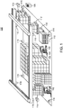
- Figure 1 illustrates a schematic, perspective view of a physical environment 100 comprising one or more embodiments of the present invention.
- the physical environment 100 further includes a floor 110 upon which a plurality of objects occupy.
- the plurality of objects include a plurality of pallets 112, a plurality of units 114 and/or the like as explained further below.
- the physical environment 100 also includes various obstructions (not pictured) to the proper operation of the vehicle 102. Some of the plurality of objects form obstacles along paths for completing tasks. These obstacles may disrupt task completion on a given vehicle path. For example, an obstacle includes a broken pallet at a target destination associated with an object load being transported. The vehicle 102 may be unable to unload the object load unless the broken pallet is removed.
- the physical environment 100 may include a warehouse for housing the plurality of units 114 in preparation for future transportation.
- warehouses may include loading docks to load and unload the plurality of units from commercial vehicles, railways, airports and/or seaports.
- the plurality of units 114 generally include various goods, products and/or raw materials and/or the like that are usually placed on one or more pallets.
- the plurality of units 114 may be consumer goods that are placed on ISO standard pallets and loaded into pallet racks by forklifts to be distributed to retail stores.
- the vehicle 102 facilitates such a distribution by moving the consumer goods to designated locations where other vehicles, (e.g., commercial trucks) load and subsequently deliver the consumer goods to one or more target destinations.
- One or more computing devices are utilized to process sensor array data and execute tasks.
- the mobile computer 104 and/or the central computer 106 control the vehicle 102 and perform various tasks within the physical environment 100.
- the mobile computer 104 is adapted to couple with the vehicle 102 as illustrated.
- the mobile computer 104 may also receive and aggregate data (e.g., laser scanner data, image data and/or any other related sensor data) that is transmitted by the sensor array 108.
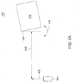
- various software modules within the central computer 106 and/or the mobile computer 104 determine orientation information associated with a particular object load (i.e., a pallet-size load) to be lifted.
- the orientation information includes measurements reflecting angular displacement and linear displacement about an x, y and z axes as explained further below.
- these measurements define an entry point orientation associated with a pallet or a rack system.
- these measurements may define a destination orientation associated with a target destination, such as a target pallet, for the particular object load.
- the various software modules within the central computer 106 and/or the mobile computer 104 extract the measurements and position the one or more lifting elements, such as the forks. Based on these measurements, the lifting elements may be positioned to optimally engage the particular object load. For example, the various software modules may align the lifting elements with entry points for the pallet or a shelf within the rack system. As another example, the various software modules may position the lifting elements to match the destination orientation associated with the target destination such that the particular object load is unloaded properly and aligned with any other object located below the same target destination.
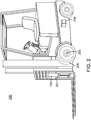
- Figure 2 illustrates a perspective view of the forklift 200 for facilitating automation of various tasks within a physical environment according to one or more embodiments of the present invention.
- Orientation information i.e., an entry point orientation
- Orientation information is used to guide the forklift 200 into the storage bay and place the pallet on cantilevered arms or rails.
- the dimensions of the forklift 200 including overall width and mast width, must be accurate when determining an orientation associated with an object and/or a target destination.
- the forklift 200 typically includes two or more forks (i.e., skids or tines) for lifting and carrying units within the physical environment.
- the forklift 200 may include one or more metal poles (not pictured) in order to lift certain units (e.g., carpet rolls, metal coils and/or the like).
- the forklift 200 includes hydraulics-powered, telescopic forks that permit two or more pallets to be placed behind each other without an aisle between these pallets.
- the lift carriage 300 is designed to raise and lower one or more lifting elements, such as forks 302, vertically in order to engage and transport object loads.
- a scanner array 321 comprising one or more laser scanners 304 and one or more cameras 306 is fitted to the lift carriage 300 (e.g., the sensor array 108 of Figure 1 ).
- the scanner array 321 may be mounted to the lift carriage 300 and retrofit object load sensing to the forklift 200.
- the camera 306 and laser 304 may form a moveable sensor head 320 according to one embodiment. When the moveable sensor head 320 is moved into a retracted position, the camera 306 and the laser sensor 304 are positioned above the forks 302.
- the sensor head 320 is attached to a pair of guide rails 308, which are attached to the mounting plate 310 through two guide bushings 312.
- the laser scanner 304 and the camera 306 may be articulated between multiple positions including, as a minimum, locations above or below the forks 302.
- the scanner array 321 includes various mechanical components that articulate (i.e., move) sensor head 320.
- a ball screw is utilized to raise or lower the laser scanner 304 and the camera 306.
- a type of mechanical components being used for articulation may depend on physical attributes associated with the forklift 200 and/or installation requirements associated with a physical environment.
- a driven linear slide table is employed to transport the laser scanner 304 and the camera 306 into various positions.
- the laser scanner 304 and/or the camera 306 located in certain positions relative to the lift carriage 300 provides these devices with a clear view beyond any object load being carried on the forks 302. Such positions further enable efficient data fitting between object models and sensor array data, which may be a combination of laser scanner data and image data, as explained further below.
- object models and sensor array data which may be a combination of laser scanner data and image data, as explained further below.
- various software modules can automatically cross correlate information between these devices, according to some embodiments.
- the various software modules use geometric transformations to perform the correlation.
- a drive motor 314 connected to a gear, which engages a rack in a rack and pinion arrangement and moves the sensor head 320 to a location above the forks 302.
- the laser scanner 304, the camera 306 and the drive motor 314 are coupled to a mobile computer (e.g., the mobile computer 104 of Figure 1 ).
- the driver motor 314 rotates the sensor head 320 when capturing the sensor array data in order to identify objects or object loads that are not directly aligned with the forks 302.
- Various software modules within the mobile computer control the drive motor 314 and store image data and laser scanner data.
- the mobile computer communicates the image data and the laser scanner to a central computer where an object recognition process is executed to identify a particular object and generate orientation information as explained in detail further below.
- the various software modules fit the matching rack system against the image as depicted in Figure 5B to compute the value for Rx 514.
- feature extraction processing techniques such as edge detection, may be utilized to identify the rack system 502 and compute the various measurements that constitute the entry point orientation of the shelf 504.
- the various software modules employ rack system model training to identify the rack system 502 and define the entry point orientation associated with the shelf 504. Using rack system model images, the various software modules are trained to determine the linear and angular displacement measurements as explained in the present disclosure. These measurements are subsequently transposed from the laser scanner 304 origin to the automated vehicle origin.
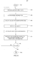
- an object recognition process is executed.
- Various software modules such as the environment sensing module (e.g., the environment sensing module 630 of Figure 6 ), perform the object recognition process (e.g., the object recognition process 628 of Figure 6 ) by comparing the sensor array data with the various object models as described in the present disclosure.
- the object recognition process may search for an object model, such as a pallet model, having similar or identical dimensions (e.g., length and width of entry points) as a particular object, such as a pallet (e.g., the pallet 112 of Figure 1 ).
- the object recognition process may utilize feature extraction processing techniques, such as edge detection, to identify the particular object, such as a rack system.
- the orientation information (e.g., the orientation information 324 of Figure 3 ) includes various linear and angular displacement measurements between the automated vehicle (e.g., the forklift 200 of Figure 2 ) and the object load (e.g., the object load 402 of Figure 4 ).
- lifting elements are moved in accordance with the entry point orientation measurements.
- the automated vehicle software positions the lifting elements into an orientation that matches the entry point orientation measurements as explained in the present disclosure.
- the object load is engaged.
Landscapes
- Engineering & Computer Science (AREA)
- Transportation (AREA)
- Structural Engineering (AREA)
- Mechanical Engineering (AREA)
- Physics & Mathematics (AREA)
- Civil Engineering (AREA)
- Life Sciences & Earth Sciences (AREA)
- Geology (AREA)
- Multimedia (AREA)
- Computer Vision & Pattern Recognition (AREA)
- Chemical & Material Sciences (AREA)
- Combustion & Propulsion (AREA)
- Electromagnetism (AREA)
- Aviation & Aerospace Engineering (AREA)
- Radar, Positioning & Navigation (AREA)
- Remote Sensing (AREA)
- General Physics & Mathematics (AREA)
- Automation & Control Theory (AREA)
- Forklifts And Lifting Vehicles (AREA)
- Warehouses Or Storage Devices (AREA)
- Control Of Position, Course, Altitude, Or Attitude Of Moving Bodies (AREA)
Claims (15)
- Procédé de pilotage d'un véhicule automatisé (102) permettant d'engager ou de désengager une charge d'objet (402) dans un environnement physique comprenant un système de crémaillère (502), consistant à :analyser une pluralité d'objets placés dans tout l'environnement physique en traitant des données transmises à partir d'un réseau de capteurs (108) fixé à un chariot élévateur (300) du véhicule (102) ;caractérisé en ce que le procédé consiste en outre à :exécuter un processus de reconnaissance d'objet (628) sur les données du réseau de capteurs (610), pour identifier le système de crémaillère (502) en comparant des modèles de système de crémaillère aux données du réseau de capteurs (610) ;utiliser l'identification du système de crémaillère et un module logiciel résidant sur un ordinateur portable (104) couplé au véhicule (102) ou un ordinateur central (106) couplé au réseau de capteurs (108) via un réseau (602), pour aligner un élément de levage (302) du véhicule (102) avec les points d'entrée d'une palette (112) ou d'une étagère (504) à l'intérieur du système de crémaillère (502) ; etengager ou désengager la charge d'objet (402) avec l'élément de levage aligné (302).
- Procédé selon la revendication 1, dans lequel :le véhicule (102) comprend des fourches de levage (302) et le réseau de capteurs (108) est positionné sous les fourches de levage (302) ; etle procédé consiste à utiliser un module logiciel résidant sur un ordinateur portable (104) couplé au véhicule (102) ou un ordinateur central (106) couplé au réseau de capteurs (108) via un réseau (602), pour déterminer si le point de destination n'est pas obstrué et désengager la charge d'objet (402) si le point de destination n'est pas obstrué.
- Procédé selon la revendication 1, dans lequel le procédé consiste à :engager une charge d'objet (402) ; etutiliser un module logiciel résidant sur un ordinateur portable (104) couplé au véhicule (102) ou un ordinateur central (106) couplé au réseau de capteurs (108) via un réseau (602), pour calculer une distance par rapport au centre de la charge d'objet (402) engagée ; etutiliser la distance calculée par rapport au centre de la charge d'objet (402) engagée et une mesure de déplacement stockée entre le véhicule (102) et la charge d'objet (402) engagée, pour calibrer le réseau de capteurs (108).
- Procédé selon la revendication 1, dans lequel le procédé consiste en outre à :scanner la charge d'objet (402) tout en déplaçant verticalement le chariot élévateur (300) et le réseau de capteurs (108) ;exécuter un processus de reconnaissance d'objet (628) sur les données du réseau de capteurs (610), pour identifier un modèle de palette correspondant ;engager ou désengager la charge d'objet (402) en fonction de l'identification du modèle de palette correspondant.
- Procédé selon la revendication 1, dans lequel le procédé consiste en outre à utiliser un module logiciel résidant sur un ordinateur portable (104) couplé au véhicule (102) ou un ordinateur central (106) couplé au réseau de capteurs (108) via un réseau (602), pour définir l'orientation d'un point d'entrée associé à une étagère (504) dans le système de crémaillère (502).
- Procédé selon la revendication 1, dans lequel :le réseau de capteurs (108) comprend une caméra (306) fixée au chariot élévateur (300) du véhicule (102) ; etles données du réseau de capteurs (610) comprennent les données enregistrées par la caméra (306).
- Procédé selon la revendication 1, dans lequel :le réseau de capteurs (108) comprend un scanner laser (304) et une caméra (306) fixée au chariot élévateur (300) du véhicule (102) ; etles données du réseau de capteurs (610) comprennent les données enregistrées par le scanner laser (304) et la caméra (306).
- Procédé selon la revendication 7, dans lequel le scanner laser (304) et la caméra (306) fonctionnent en association avec une lumière (318) pour améliorer l'identification des obstructions.
- Procédé selon la revendication 1, dans lequel le réseau de capteurs (108) comprend un scanner laser (304) et une caméra (306) fixée au chariot élévateur (300) du véhicule (102) sous la forme d'une tête de capteur mobile (320) fixée à une paire de rails de guidage (308).
- Procédé selon la revendication 9, dans lequel une vis à bille est utilisée pour lever ou abaisser la tête de capteur (320) ou une table coulissante linéaire entraînée est utilisée pour transporter la tête de capteur (320).
- Procédé selon la revendication 9, dans lequel :le véhicule (102) comprend des fourches de levage (302) et un moteur d'entraînement (314) relié à un engrenage, qui engage une crémaillère dans un agencement à crémaillère et pignon ; etle procédé consiste à utiliser l'agencement à crémaillère et pignon pour déplacer la tête de capteur (320) jusqu'à un emplacement au-dessus des fourches de levage (302), en dessous des fourches de levage (302).
- Procédé selon la revendication 11, dans lequel le procédé consiste à mettre en rotation la tête de capteur (320) avec le moteur d'entraînement (314) lors de l'enregistrement des données de réseau de capteurs (610) afin d'identifier les objets ou les charges d'objets (402) qui ne sont pas directement alignés avec les fourches (302).
- Procédé selon la revendication 1, dans lequel :le réseau de capteurs (108) comprend un scanner laser (304) et une caméra (306) fixée au chariot élévateur (300) du véhicule (102) ;le scanner laser (304) et la caméra (306) sont colinéaires et orthogonaux dans le plan horizontal et coplanaires dans le plan vertical par rapport à l'axe d'un véhicule automatisé ; etle procédé consiste à utiliser un module logiciel résidant sur un ordinateur portable (104) couplé au véhicule (102) ou un ordinateur central (106) couplé au réseau de capteurs (108) via un réseau (602), pour établir automatiquement des corrélations croisées entre les informations du scanner laser (304) et de la caméra (306).
- Procédé selon la revendication 1, dans lequel :le réseau de capteurs (108) comprend un scanner laser (304) et une caméra (306) fixée au chariot élévateur (300) du véhicule (102) ;le procédé consiste à utiliser un module logiciel résidant sur un ordinateur portable (104) couplé au véhicule (102) ou un ordinateur central (106) couplé au réseau de capteurs (108) via un réseau (602), pour utiliser les transformations géométriques afin d'établir des corrélations croisées entre les informations du scanner laser (304) et de la caméra (306).
- Système de pilotage d'un véhicule automatisé (102) permettant d'engager ou de désengager une charge d'objet (402) dans un environnement physique comprenant une crémaillère, le système comprenant un ordinateur portable (104) couplé au véhicule (102), un ordinateur central (106) et un réseau de capteurs (108) fixé à un chariot élévateur (300) du véhicule (102), dans lequel :l'ordinateur portable (104), l'ordinateur central (106) et le réseau de capteurs (108) sont couplés les uns aux autres via un réseau (602) ; etcaractérisé en ce que les modules logiciels dans l'ordinateur central (106), l'ordinateur portable (104), ou les deux, traitent les données transmises par le réseau de capteurs (108) pour faciliter l'engagement ou le désengagement de la charge d'objet (402) en :exécutant un processus de reconnaissance d'objet (628) sur les données du réseau de capteurs (610), pour identifier le système de crémaillère (502) en comparant des modèles de système de crémaillère aux données du réseau de capteurs (610),utilisant l'identification du système de crémaillère et un module logiciel résidant sur un ordinateur portable (104) couplé au véhicule (102) ou un ordinateur central (106) couplé au réseau de capteurs (108) via un réseau (602), pour aligner un élément de levage (302) du véhicule (102) avec les points d'entrée d'une palette (112) ou d'une étagère (504) à l'intérieur du système de crémaillère (502), etengageant ou désengageant la charge d'objet (402) avec l'élément de levage aligné (302).
Applications Claiming Priority (2)
| Application Number | Priority Date | Filing Date | Title |
|---|---|---|---|
| US12/718,620 US8538577B2 (en) | 2010-03-05 | 2010-03-05 | Method and apparatus for sensing object load engagement, transportation and disengagement by automated vehicles |
| PCT/NZ2011/000024 WO2011108944A2 (fr) | 2010-03-05 | 2011-02-17 | Procédé et appareil de détection de prise de charge, de transport et de libération d'objet par des véhicules automatisés |
Publications (3)
| Publication Number | Publication Date |
|---|---|
| EP2542496A2 EP2542496A2 (fr) | 2013-01-09 |
| EP2542496A4 EP2542496A4 (fr) | 2016-06-15 |
| EP2542496B1 true EP2542496B1 (fr) | 2018-05-23 |
Family
ID=44532020
Family Applications (1)
| Application Number | Title | Priority Date | Filing Date |
|---|---|---|---|
| EP11750973.7A Active EP2542496B1 (fr) | 2010-03-05 | 2011-02-17 | Procédé et système de détection d' engagement et de désengagement de charges transportées par des véhicules automatisés |
Country Status (5)
| Country | Link |
|---|---|
| US (1) | US8538577B2 (fr) |
| EP (1) | EP2542496B1 (fr) |
| AU (1) | AU2011221652B2 (fr) |
| CA (1) | CA2791842C (fr) |
| WO (1) | WO2011108944A2 (fr) |
Families Citing this family (56)
| Publication number | Priority date | Publication date | Assignee | Title |
|---|---|---|---|---|
| WO2011009020A2 (fr) | 2009-07-16 | 2011-01-20 | Mallinckrodt Inc. | Composés et compositions pour une utilisation en photothérapie et dans le traitement d'une maladie néovasculaire oculaire et de cancers |
| JP5503419B2 (ja) * | 2010-06-03 | 2014-05-28 | 株式会社日立製作所 | 無人搬送車および走行制御方法 |
| CN102583194B (zh) * | 2011-01-04 | 2014-03-26 | 瀚宇彩晶股份有限公司 | 根据货物重量以提供运输信息的堆高机及其相关方法 |
| US20120191272A1 (en) * | 2011-01-24 | 2012-07-26 | Sky-Trax, Inc. | Inferential load tracking |
| CA2831832C (fr) | 2011-04-11 | 2021-06-15 | Crown Equipment Limited | Procede et appareil pour une planification efficace pour de multiples vehicules non holonomiques automatises a l'aide d'un planificateur de trajet coordonne |
| US8655588B2 (en) | 2011-05-26 | 2014-02-18 | Crown Equipment Limited | Method and apparatus for providing accurate localization for an industrial vehicle |
| US8548671B2 (en) | 2011-06-06 | 2013-10-01 | Crown Equipment Limited | Method and apparatus for automatically calibrating vehicle parameters |
| US20140058634A1 (en) | 2012-08-24 | 2014-02-27 | Crown Equipment Limited | Method and apparatus for using unique landmarks to locate industrial vehicles at start-up |
| US9056754B2 (en) | 2011-09-07 | 2015-06-16 | Crown Equipment Limited | Method and apparatus for using pre-positioned objects to localize an industrial vehicle |
| CN103889879B (zh) | 2011-10-19 | 2017-03-22 | 克朗设备公司 | 识别、匹配并跟踪图像序列中的多个对象 |
| EP2815353B1 (fr) * | 2012-02-17 | 2019-05-08 | Columbus McKinnon Corporation | Procédé et système de levage de matériaux |
| US10216865B1 (en) * | 2012-03-06 | 2019-02-26 | Vecna Robotics, Inc. | Monitoring one or more articles on a support surface |
| US10028878B1 (en) | 2012-11-28 | 2018-07-24 | Vecna Technologies, Inc. | Body worn apparatus |
| US9415983B2 (en) * | 2012-12-17 | 2016-08-16 | Shamrock Foods Company | Crash prevention system for a storage and retrieval machine |
| NL2011132C2 (en) * | 2013-07-10 | 2015-01-13 | Stertil Bv | Lifting system for lifting a vehicle and method for operating the lifting system. |
| US9354070B2 (en) | 2013-10-31 | 2016-05-31 | Crown Equipment Corporation | Systems, methods, and industrial vehicles for determining the visibility of features |
| US20150269501A1 (en) * | 2014-03-18 | 2015-09-24 | Ghostruck Co | System and process for resource allocation to relocate physical objects |
| WO2016043998A1 (fr) | 2014-09-15 | 2016-03-24 | Crown Equipment Corporation | Chariot élévateur comprenant une structure de détection de charge optique |
| EP3000771B1 (fr) * | 2014-09-25 | 2017-11-22 | Toyota Material Handling Manufacturing Sweden AB | Chariot élévateur à fourche |
| US9734639B2 (en) * | 2014-12-31 | 2017-08-15 | Hand Held Products, Inc. | System and method for monitoring an industrial vehicle |
| WO2016142794A1 (fr) | 2015-03-06 | 2016-09-15 | Wal-Mart Stores, Inc | Système et procédé de surveillance d'élément |
| US20180099846A1 (en) | 2015-03-06 | 2018-04-12 | Wal-Mart Stores, Inc. | Method and apparatus for transporting a plurality of stacked motorized transport units |
| US20160260142A1 (en) | 2015-03-06 | 2016-09-08 | Wal-Mart Stores, Inc. | Shopping facility assistance systems, devices and methods to support requesting in-person assistance |
| US12084824B2 (en) | 2015-03-06 | 2024-09-10 | Walmart Apollo, Llc | Shopping facility assistance systems, devices and methods |
| WO2016168650A1 (fr) * | 2015-04-15 | 2016-10-20 | Volvo Truck Corporation | Système de guidage de véhicule |
| JP6469506B2 (ja) | 2015-04-16 | 2019-02-13 | 株式会社豊田中央研究所 | フォークリフト |
| JP6542574B2 (ja) * | 2015-05-12 | 2019-07-10 | 株式会社豊田中央研究所 | フォークリフト |
| US10556722B2 (en) | 2015-07-08 | 2020-02-11 | Divert, Inc. | System for tracking waste or recyclable material |
| EP3322564A4 (fr) * | 2015-07-16 | 2019-03-20 | Sikorsky Aircraft Corporation | Système capteur de jeu |
| CN105502226A (zh) * | 2016-01-26 | 2016-04-20 | 东莞双成电子塑胶有限公司 | 一种叉车货叉镭射定位辅助装置 |
| CA2961938A1 (fr) | 2016-04-01 | 2017-10-01 | Wal-Mart Stores, Inc. | Systemes et methodes de deplacement de palettes au moyen de chariots elevateurs a fourche motorises autonomes |
| US9990535B2 (en) | 2016-04-27 | 2018-06-05 | Crown Equipment Corporation | Pallet detection using units of physical length |
| US10380473B2 (en) * | 2016-06-24 | 2019-08-13 | Crown Equipment Corporation | Indirect electronic badge tracking |
| JP6451715B2 (ja) | 2016-10-14 | 2019-01-16 | 株式会社豊田自動織機 | フォークリフト |
| US10048398B2 (en) * | 2016-10-31 | 2018-08-14 | X Development Llc | Methods and systems for pallet detection |
| US10328578B2 (en) | 2017-04-21 | 2019-06-25 | X Development Llc | Methods and systems for detecting, recognizing, and localizing pallets |
| US10538421B2 (en) * | 2017-05-05 | 2020-01-21 | Atlantic Corporation | Systems, devices, and methods for inventory management of carpet rolls in a warehouse |
| US10655945B2 (en) * | 2017-07-19 | 2020-05-19 | Symbol Technologies, Llc | Methods and apparatus to coordinate movement of automated vehicles and freight dimensioning components |
| US10394234B2 (en) | 2017-12-18 | 2019-08-27 | The Boeing Company | Multi-sensor safe path system for autonomous vehicles |
| US11416001B2 (en) | 2018-07-17 | 2022-08-16 | Crown Equipment Corporation | Systems and methods for vehicle position calibration using rack leg identification |
| US11379788B1 (en) | 2018-10-09 | 2022-07-05 | Fida, Llc | Multilayered method and apparatus to facilitate the accurate calculation of freight density, area, and classification and provide recommendations to optimize shipping efficiency |
| US10369701B1 (en) | 2018-10-30 | 2019-08-06 | Mujin, Inc. | Automated package registration systems, devices, and methods |
| WO2020091846A1 (fr) | 2018-10-30 | 2020-05-07 | Mujin, Inc. | Systèmes, appareils et procédés d'enregistrement d'emballage automatisés |
| AU2020219110A1 (en) | 2019-02-06 | 2021-08-26 | Crown Equipment Corporation | Systems and methods for end of aisle protection and vehicle position calibration using rack leg identification |
| EP3950566B1 (fr) | 2019-04-02 | 2024-03-20 | Beijing Geekplus Technology Co., Ltd. | Robot à position haute, procédé d'étalonnage du retour d'un conteneur de stockage et support de stockage |
| CN109987550B (zh) * | 2019-04-04 | 2021-03-19 | 北京极智嘉科技有限公司 | 一种高位叉车、归还仓储容器的校准方法及存储介质 |
| US11591197B2 (en) | 2019-04-05 | 2023-02-28 | The Raymond Corporation | Load handling module for a material handling vehicle |
| WO2020210397A1 (fr) * | 2019-04-08 | 2020-10-15 | Lineage Logistics, LLC | Transport automatique de palettes de marchandises |
| CA3149155A1 (fr) | 2019-09-18 | 2021-03-25 | Nicholas L. Whitman | Systemes et procedes de suivi d'environnement de produit a travers une chaine d'approvisionnement |
| DE102020105215A1 (de) * | 2020-02-27 | 2021-09-02 | Jungheinrich Aktiengesellschaft | Verfahren zum Kalibrieren einer Sensoreinheit eines Flurförderzeugs |
| WO2021197785A1 (fr) | 2020-04-01 | 2021-10-07 | Sew-Eurodrive Gmbh & Co. Kg | Système mobile et procédé de fonctionnement d'un système mobile |
| WO2022072616A1 (fr) * | 2020-09-30 | 2022-04-07 | Seegrid Corporation | Système et procédé de balayage et de mise en prise d'objet de véhicule |
| WO2023230330A1 (fr) * | 2022-05-27 | 2023-11-30 | Seegrid Corporation | Système et procédé pour effectuer des interactions avec des objets physiques sur la base de la fusion de multiples capteurs |
| US20230400858A1 (en) * | 2022-06-10 | 2023-12-14 | Autoguide, LLC | Identifying transport structures |
| FR3137031A1 (fr) * | 2022-06-22 | 2023-12-29 | Compagnie Generale Des Etablissements Michelin | Chariot élévateur autonome de transport de charge et procédé associé |
| FR3137077A1 (fr) * | 2022-06-22 | 2023-12-29 | Compagnie Generale Des Etablissements Michelin | Chariot élévateur autonome de levage et transport de charge, et procédé associé |
Family Cites Families (77)
| Publication number | Priority date | Publication date | Assignee | Title |
|---|---|---|---|---|
| JPS6067818A (ja) | 1983-09-22 | 1985-04-18 | Hitachi Ltd | 車載用ナビゲ−タ |
| US4855915A (en) * | 1987-03-13 | 1989-08-08 | Dallaire Rodney J | Autoguided vehicle using reflective materials |
| US4858132A (en) * | 1987-09-11 | 1989-08-15 | Ndc Technologies, Inc. | Optical navigation system for an automatic guided vehicle, and method |
| US5011358A (en) * | 1988-10-25 | 1991-04-30 | Andersen Eric T | Height indicator for a fork lift truck |
| US5179329A (en) * | 1989-04-25 | 1993-01-12 | Shinko Electric Co., Ltd. | Travel control method, travel control device, and mobile robot for mobile robot systems |
| US5051906A (en) * | 1989-06-07 | 1991-09-24 | Transitions Research Corporation | Mobile robot navigation employing retroreflective ceiling features |
| US5838562A (en) * | 1990-02-05 | 1998-11-17 | Caterpillar Inc. | System and a method for enabling a vehicle to track a preset path |
| US5170352A (en) * | 1990-05-07 | 1992-12-08 | Fmc Corporation | Multi-purpose autonomous vehicle with path plotting |
| US5202832A (en) * | 1991-01-29 | 1993-04-13 | R. R. Donnelley & Sons Co. | Material handling automation system using portable transfer module |
| US5258911A (en) | 1991-04-09 | 1993-11-02 | Crown Equipment Corporation | End of aisle control system |
| US5491670A (en) * | 1993-01-21 | 1996-02-13 | Weber; T. Jerome | System and method for sonic positioning |
| US5539638A (en) * | 1993-08-05 | 1996-07-23 | Pavilion Technologies, Inc. | Virtual emissions monitor for automobile |
| US5471393A (en) * | 1994-01-26 | 1995-11-28 | Bolger; Joe | Driver's associate: a system for vehicle navigation and driving assistance |
| US5961571A (en) * | 1994-12-27 | 1999-10-05 | Siemens Corporated Research, Inc | Method and apparatus for automatically tracking the location of vehicles |
| US5916285A (en) * | 1995-10-18 | 1999-06-29 | Jervis B. Webb Company | Method and apparatus for sensing forward, reverse and lateral motion of a driverless vehicle |
| DE19613386A1 (de) * | 1996-04-03 | 1997-10-09 | Fiat Om Carrelli Elevatori | Flurförderzeug, das wahlweise manuell oder automatisch betreibbar ausgebildet ist |
| SE9601440D0 (sv) * | 1996-04-15 | 1996-04-15 | Apogeum Ab | Förfarande för positionsbestämning av ett flertal fasta objekt |
| US6092010A (en) * | 1997-09-03 | 2000-07-18 | Jervis B. Webb Company | Method and system for describing, generating and checking non-wire guidepaths for automatic guided vehicles |
| SE511504C2 (sv) * | 1997-10-17 | 1999-10-11 | Apogeum Ab | Sätt och anordning för associering av anonyma reflektorer till detekterade vinkellägen |
| DE19757333C1 (de) | 1997-12-22 | 1999-09-16 | Litef Gmbh | Selbsttätige, schnelle Kalibrierung einer bordautonomen Messung eines Geschwindigkeitsvektors |
| JPH11296229A (ja) * | 1998-02-13 | 1999-10-29 | Komatsu Ltd | 車両の誘導装置 |
| JP3316842B2 (ja) * | 1998-08-06 | 2002-08-19 | 村田機械株式会社 | 無人搬送車システムと無人搬送車の誘導方法 |
| JP3316841B2 (ja) * | 1998-08-06 | 2002-08-19 | 村田機械株式会社 | 無人搬送車システム |
| US7123166B1 (en) * | 2000-11-17 | 2006-10-17 | Haynes Michael N | Method for managing a parking lot |
| JP2002048579A (ja) | 2000-04-28 | 2002-02-15 | Matsushita Electric Ind Co Ltd | 通信型ナビゲーションシステム |
| US6917839B2 (en) * | 2000-06-09 | 2005-07-12 | Intellectual Assets Llc | Surveillance system and method having an operating mode partitioned fault classification model |
| JP2002108446A (ja) | 2000-09-29 | 2002-04-10 | Nippon Seiki Co Ltd | 移動体の誘導方法 |
| US6428439B1 (en) * | 2000-10-04 | 2002-08-06 | Gkn Automotive, Inc. | Integrated viscous transmission in a differential |
| US6952488B2 (en) * | 2001-08-27 | 2005-10-04 | Carnegie Mellon University | System and method for object localization |
| US6669089B2 (en) | 2001-11-12 | 2003-12-30 | 3M Innovative Properties Co | Radio frequency identification systems for asset tracking |
| JP3968501B2 (ja) * | 2001-11-30 | 2007-08-29 | ソニー株式会社 | ロボットの自己位置同定システム及び自己位置同定方法 |
| US7844364B2 (en) * | 2002-04-16 | 2010-11-30 | Irobot Corporation | Systems and methods for dispersing and clustering a plurality of robotic devices |
| AU2003223090A1 (en) * | 2002-04-30 | 2003-11-17 | Telmap Ltd. | Template-based map distribution system |
| US20050149256A1 (en) * | 2002-05-10 | 2005-07-07 | Siemens Aktiengesellschaft | Device for determining the position by means of fixed and/or variable landmarks |
| DE10220936A1 (de) | 2002-05-10 | 2003-12-04 | Siemens Ag | Vorrichtung zur Lokalisierung mit festen und/oder veränderlichen Landmarken |
| GB2389947B (en) | 2002-07-25 | 2004-06-02 | Golden River Traffic Ltd | Automatic validation of sensing devices |
| DE10234730A1 (de) | 2002-07-30 | 2004-02-19 | Josef Schreiner | Verfahren zur Positionsbestimmung eines Transportfahrzeuges |
| US7135992B2 (en) * | 2002-12-17 | 2006-11-14 | Evolution Robotics, Inc. | Systems and methods for using multiple hypotheses in a visual simultaneous localization and mapping system |
| KR100506533B1 (ko) * | 2003-01-11 | 2005-08-05 | 삼성전자주식회사 | 이동로봇 및 그에 따른 자율주행 시스템 및 방법 |
| DE10323641A1 (de) * | 2003-05-26 | 2005-01-05 | Daimlerchrysler Ag | Bewegliche Sensoreinrichtung am Lastmittel eines Gabelstaplers |
| JP4409904B2 (ja) | 2003-10-08 | 2010-02-03 | 株式会社日立製作所 | 経路情報提供システムおよび経路情報提供方法 |
| DE102004001197A1 (de) | 2004-01-07 | 2005-08-04 | Daimlerchrysler Ag | Verfahren zum Betrieb eines sehenden autonomen Transportfahrzeugs für den Abtransport von Leergut |
| US7689321B2 (en) * | 2004-02-13 | 2010-03-30 | Evolution Robotics, Inc. | Robust sensor fusion for mapping and localization in a simultaneous localization and mapping (SLAM) system |
| WO2005086375A1 (fr) | 2004-03-03 | 2005-09-15 | Nec Corporation | Systeme de positionnement, methode de positionnement et programme connexe |
| KR100571837B1 (ko) * | 2004-03-05 | 2006-04-17 | 삼성전자주식회사 | 자율주행기기의 주행제어방법 및 장치 |
| US7720554B2 (en) * | 2004-03-29 | 2010-05-18 | Evolution Robotics, Inc. | Methods and apparatus for position estimation using reflected light sources |
| US7148458B2 (en) * | 2004-03-29 | 2006-12-12 | Evolution Robotics, Inc. | Circuit for estimating position and orientation of a mobile object |
| KR100703692B1 (ko) * | 2004-11-03 | 2007-04-05 | 삼성전자주식회사 | 공간상에 존재하는 오브젝트들을 구별하기 위한 시스템,장치 및 방법 |
| US20100222925A1 (en) * | 2004-12-03 | 2010-09-02 | Takashi Anezaki | Robot control apparatus |
| US7845560B2 (en) * | 2004-12-14 | 2010-12-07 | Sky-Trax Incorporated | Method and apparatus for determining position and rotational orientation of an object |
| US8497761B2 (en) * | 2005-01-13 | 2013-07-30 | Rite-Hite Holding Corporation | System and method for remotely controlling docking station components |
| US8930023B2 (en) * | 2009-11-06 | 2015-01-06 | Irobot Corporation | Localization by learning of wave-signal distributions |
| WO2007028049A2 (fr) * | 2005-09-02 | 2007-03-08 | Neato Robotics, Inc. | Dispositif robotique multifonction |
| GB0520576D0 (en) * | 2005-10-10 | 2005-11-16 | Applied Generics Ltd | Using traffic monitoring information to provide better driver route planning |
| WO2007050407A1 (fr) * | 2005-10-21 | 2007-05-03 | Deere & Company | Systemes et procedes de commutation entre des mode de conduite autonome et manuel d'un vehicule |
| US8381982B2 (en) * | 2005-12-03 | 2013-02-26 | Sky-Trax, Inc. | Method and apparatus for managing and controlling manned and automated utility vehicles |
| US7634336B2 (en) * | 2005-12-08 | 2009-12-15 | Electronics And Telecommunications Research Institute | Localization system and method of mobile robot based on camera and landmarks |
| US7616642B2 (en) * | 2006-01-04 | 2009-11-10 | Sap Ag | Priority assignment and transmission of sensor data |
| US20070213869A1 (en) * | 2006-02-08 | 2007-09-13 | Intermec Ip Corp. | Cargo transporter with automatic data collection devices |
| US8050863B2 (en) * | 2006-03-16 | 2011-11-01 | Gray & Company, Inc. | Navigation and control system for autonomous vehicles |
| US7646336B2 (en) * | 2006-03-24 | 2010-01-12 | Containertrac, Inc. | Automated asset positioning for location and inventory tracking using multiple positioning techniques |
| JP4975503B2 (ja) * | 2007-04-06 | 2012-07-11 | 本田技研工業株式会社 | 脚式移動ロボット |
| JP4328813B2 (ja) * | 2007-04-06 | 2009-09-09 | 本田技研工業株式会社 | 移動装置、ならびにその制御方法および制御プログラム |
| DE102007021693A1 (de) | 2007-05-09 | 2008-11-13 | Götting jun., Hans-Heinrich, Dipl.-Ing. (FH) | Hilfssystem zur Lagebestimmung eines Fahrzeugs |
| US8930127B2 (en) * | 2007-07-12 | 2015-01-06 | Carmel—Haifa University Economic Corp Ltd. | Localization method for mobile robots based on landmarks |
| US20090140887A1 (en) * | 2007-11-29 | 2009-06-04 | Breed David S | Mapping Techniques Using Probe Vehicles |
| US20090216438A1 (en) * | 2008-02-21 | 2009-08-27 | Microsoft Corporation | Facility map framework |
| DE102008027701B4 (de) | 2008-04-20 | 2022-10-06 | Still Gesellschaft Mit Beschränkter Haftung | Steuerungsverfahren für Flurförderzeug |
| US8126642B2 (en) * | 2008-10-24 | 2012-02-28 | Gray & Company, Inc. | Control and systems for autonomously driven vehicles |
| JP4655139B2 (ja) * | 2008-11-19 | 2011-03-23 | トヨタ自動車株式会社 | 移動体位置測位装置 |
| KR101214143B1 (ko) * | 2008-12-22 | 2012-12-20 | 한국전자통신연구원 | 이동체의 위치 및 방향 인식 장치 및 그 방법 |
| WO2011064821A1 (fr) * | 2009-11-27 | 2011-06-03 | トヨタ自動車株式会社 | Objet mobile autonome et procédé de contrôle |
| US20110153338A1 (en) * | 2009-12-17 | 2011-06-23 | Noel Wayne Anderson | System and method for deploying portable landmarks |
| US8340438B2 (en) * | 2009-12-17 | 2012-12-25 | Deere & Company | Automated tagging for landmark identification |
| US20120101784A1 (en) * | 2010-10-25 | 2012-04-26 | Trimble Navigation Limited | Wide-area agricultural monitoring and prediction |
| US20120191272A1 (en) * | 2011-01-24 | 2012-07-26 | Sky-Trax, Inc. | Inferential load tracking |
| US8594923B2 (en) * | 2011-06-14 | 2013-11-26 | Crown Equipment Limited | Method and apparatus for sharing map data associated with automated industrial vehicles |
-
2010
- 2010-03-05 US US12/718,620 patent/US8538577B2/en active Active
-
2011
- 2011-02-17 WO PCT/NZ2011/000024 patent/WO2011108944A2/fr active Application Filing
- 2011-02-17 EP EP11750973.7A patent/EP2542496B1/fr active Active
- 2011-02-17 CA CA2791842A patent/CA2791842C/fr active Active
- 2011-02-17 AU AU2011221652A patent/AU2011221652B2/en active Active
Non-Patent Citations (1)
| Title |
|---|
| None * |
Also Published As
| Publication number | Publication date |
|---|---|
| AU2011221652A8 (en) | 2012-09-20 |
| CA2791842C (fr) | 2015-10-20 |
| WO2011108944A8 (fr) | 2011-11-10 |
| US8538577B2 (en) | 2013-09-17 |
| AU2011221652A1 (en) | 2012-09-13 |
| EP2542496A4 (fr) | 2016-06-15 |
| EP2542496A2 (fr) | 2013-01-09 |
| US20110218670A1 (en) | 2011-09-08 |
| CA2791842A1 (fr) | 2011-09-09 |
| WO2011108944A2 (fr) | 2011-09-09 |
| WO2011108944A3 (fr) | 2012-02-02 |
| AU2011221652B2 (en) | 2014-11-13 |
Similar Documents
| Publication | Publication Date | Title |
|---|---|---|
| EP2542496B1 (fr) | Procédé et système de détection d' engagement et de désengagement de charges transportées par des véhicules automatisés | |
| US10611613B2 (en) | Systems and methods for pose development using retrieved position of a pallet or product load to be picked up | |
| US8508590B2 (en) | Method and apparatus for simulating a physical environment to facilitate vehicle operation and task completion | |
| EP3792722B1 (fr) | Procédé et appareil d'utilisation de repères terrestres uniques pour localiser des véhicules industriels au démarrage | |
| US8548671B2 (en) | Method and apparatus for automatically calibrating vehicle parameters | |
| EP2753997B1 (fr) | Procédé et appareil pour utiliser des objets prépositionnés afin de localiser un véhicule industriel | |
| US9056754B2 (en) | Method and apparatus for using pre-positioned objects to localize an industrial vehicle | |
| AU2016266099B2 (en) | Method and apparatus for using unique landmarks to locate industrial vehicles at start-up | |
| AU2015203030B2 (en) | Method and apparatus for using unique landmarks to locate industrial vehicles at start-up |
Legal Events
| Date | Code | Title | Description |
|---|---|---|---|
| PUAI | Public reference made under article 153(3) epc to a published international application that has entered the european phase |
Free format text: ORIGINAL CODE: 0009012 |
|
| 17P | Request for examination filed |
Effective date: 20120924 |
|
| AK | Designated contracting states |
Kind code of ref document: A2 Designated state(s): AL AT BE BG CH CY CZ DE DK EE ES FI FR GB GR HR HU IE IS IT LI LT LU LV MC MK MT NL NO PL PT RO RS SE SI SK SM TR |
|
| DAX | Request for extension of the european patent (deleted) | ||
| A4 | Supplementary search report drawn up and despatched |
Effective date: 20160517 |
|
| RIC1 | Information provided on ipc code assigned before grant |
Ipc: B66F 9/075 20060101ALI20160510BHEP Ipc: B66C 13/18 20060101ALI20160510BHEP Ipc: B66F 9/20 20060101AFI20160510BHEP Ipc: G05D 1/02 20060101ALI20160510BHEP Ipc: B66C 13/40 20060101ALI20160510BHEP |
|
| RAP1 | Party data changed (applicant data changed or rights of an application transferred) |
Owner name: CROWN EQUIPMENT CORPORATION |
|
| STAA | Information on the status of an ep patent application or granted ep patent |
Free format text: STATUS: EXAMINATION IS IN PROGRESS |
|
| 17Q | First examination report despatched |
Effective date: 20170410 |
|
| GRAP | Despatch of communication of intention to grant a patent |
Free format text: ORIGINAL CODE: EPIDOSNIGR1 |
|
| STAA | Information on the status of an ep patent application or granted ep patent |
Free format text: STATUS: GRANT OF PATENT IS INTENDED |
|
| INTG | Intention to grant announced |
Effective date: 20171201 |
|
| GRAS | Grant fee paid |
Free format text: ORIGINAL CODE: EPIDOSNIGR3 |
|
| GRAA | (expected) grant |
Free format text: ORIGINAL CODE: 0009210 |
|
| STAA | Information on the status of an ep patent application or granted ep patent |
Free format text: STATUS: THE PATENT HAS BEEN GRANTED |
|
| AK | Designated contracting states |
Kind code of ref document: B1 Designated state(s): AL AT BE BG CH CY CZ DE DK EE ES FI FR GB GR HR HU IE IS IT LI LT LU LV MC MK MT NL NO PL PT RO RS SE SI SK SM TR |
|
| REG | Reference to a national code |
Ref country code: GB Ref legal event code: FG4D |
|
| REG | Reference to a national code |
Ref country code: CH Ref legal event code: EP |
|
| REG | Reference to a national code |
Ref country code: IE Ref legal event code: FG4D |
|
| REG | Reference to a national code |
Ref country code: AT Ref legal event code: REF Ref document number: 1001368 Country of ref document: AT Kind code of ref document: T Effective date: 20180615 |
|
| REG | Reference to a national code |
Ref country code: DE Ref legal event code: R096 Ref document number: 602011048584 Country of ref document: DE |
|
| REG | Reference to a national code |
Ref country code: NL Ref legal event code: MP Effective date: 20180523 |
|
| REG | Reference to a national code |
Ref country code: LT Ref legal event code: MG4D |
|
| PG25 | Lapsed in a contracting state [announced via postgrant information from national office to epo] |
Ref country code: ES Free format text: LAPSE BECAUSE OF FAILURE TO SUBMIT A TRANSLATION OF THE DESCRIPTION OR TO PAY THE FEE WITHIN THE PRESCRIBED TIME-LIMIT Effective date: 20180523 Ref country code: FI Free format text: LAPSE BECAUSE OF FAILURE TO SUBMIT A TRANSLATION OF THE DESCRIPTION OR TO PAY THE FEE WITHIN THE PRESCRIBED TIME-LIMIT Effective date: 20180523 Ref country code: BG Free format text: LAPSE BECAUSE OF FAILURE TO SUBMIT A TRANSLATION OF THE DESCRIPTION OR TO PAY THE FEE WITHIN THE PRESCRIBED TIME-LIMIT Effective date: 20180823 Ref country code: LT Free format text: LAPSE BECAUSE OF FAILURE TO SUBMIT A TRANSLATION OF THE DESCRIPTION OR TO PAY THE FEE WITHIN THE PRESCRIBED TIME-LIMIT Effective date: 20180523 Ref country code: SE Free format text: LAPSE BECAUSE OF FAILURE TO SUBMIT A TRANSLATION OF THE DESCRIPTION OR TO PAY THE FEE WITHIN THE PRESCRIBED TIME-LIMIT Effective date: 20180523 Ref country code: NO Free format text: LAPSE BECAUSE OF FAILURE TO SUBMIT A TRANSLATION OF THE DESCRIPTION OR TO PAY THE FEE WITHIN THE PRESCRIBED TIME-LIMIT Effective date: 20180823 |
|
| PG25 | Lapsed in a contracting state [announced via postgrant information from national office to epo] |
Ref country code: GR Free format text: LAPSE BECAUSE OF FAILURE TO SUBMIT A TRANSLATION OF THE DESCRIPTION OR TO PAY THE FEE WITHIN THE PRESCRIBED TIME-LIMIT Effective date: 20180824 Ref country code: RS Free format text: LAPSE BECAUSE OF FAILURE TO SUBMIT A TRANSLATION OF THE DESCRIPTION OR TO PAY THE FEE WITHIN THE PRESCRIBED TIME-LIMIT Effective date: 20180523 Ref country code: HR Free format text: LAPSE BECAUSE OF FAILURE TO SUBMIT A TRANSLATION OF THE DESCRIPTION OR TO PAY THE FEE WITHIN THE PRESCRIBED TIME-LIMIT Effective date: 20180523 Ref country code: LV Free format text: LAPSE BECAUSE OF FAILURE TO SUBMIT A TRANSLATION OF THE DESCRIPTION OR TO PAY THE FEE WITHIN THE PRESCRIBED TIME-LIMIT Effective date: 20180523 Ref country code: NL Free format text: LAPSE BECAUSE OF FAILURE TO SUBMIT A TRANSLATION OF THE DESCRIPTION OR TO PAY THE FEE WITHIN THE PRESCRIBED TIME-LIMIT Effective date: 20180523 |
|
| REG | Reference to a national code |
Ref country code: AT Ref legal event code: MK05 Ref document number: 1001368 Country of ref document: AT Kind code of ref document: T Effective date: 20180523 |
|
| PG25 | Lapsed in a contracting state [announced via postgrant information from national office to epo] |
Ref country code: CZ Free format text: LAPSE BECAUSE OF FAILURE TO SUBMIT A TRANSLATION OF THE DESCRIPTION OR TO PAY THE FEE WITHIN THE PRESCRIBED TIME-LIMIT Effective date: 20180523 Ref country code: RO Free format text: LAPSE BECAUSE OF FAILURE TO SUBMIT A TRANSLATION OF THE DESCRIPTION OR TO PAY THE FEE WITHIN THE PRESCRIBED TIME-LIMIT Effective date: 20180523 Ref country code: SK Free format text: LAPSE BECAUSE OF FAILURE TO SUBMIT A TRANSLATION OF THE DESCRIPTION OR TO PAY THE FEE WITHIN THE PRESCRIBED TIME-LIMIT Effective date: 20180523 Ref country code: PL Free format text: LAPSE BECAUSE OF FAILURE TO SUBMIT A TRANSLATION OF THE DESCRIPTION OR TO PAY THE FEE WITHIN THE PRESCRIBED TIME-LIMIT Effective date: 20180523 Ref country code: AT Free format text: LAPSE BECAUSE OF FAILURE TO SUBMIT A TRANSLATION OF THE DESCRIPTION OR TO PAY THE FEE WITHIN THE PRESCRIBED TIME-LIMIT Effective date: 20180523 Ref country code: DK Free format text: LAPSE BECAUSE OF FAILURE TO SUBMIT A TRANSLATION OF THE DESCRIPTION OR TO PAY THE FEE WITHIN THE PRESCRIBED TIME-LIMIT Effective date: 20180523 Ref country code: EE Free format text: LAPSE BECAUSE OF FAILURE TO SUBMIT A TRANSLATION OF THE DESCRIPTION OR TO PAY THE FEE WITHIN THE PRESCRIBED TIME-LIMIT Effective date: 20180523 |
|
| REG | Reference to a national code |
Ref country code: DE Ref legal event code: R097 Ref document number: 602011048584 Country of ref document: DE |
|
| PG25 | Lapsed in a contracting state [announced via postgrant information from national office to epo] |
Ref country code: IT Free format text: LAPSE BECAUSE OF FAILURE TO SUBMIT A TRANSLATION OF THE DESCRIPTION OR TO PAY THE FEE WITHIN THE PRESCRIBED TIME-LIMIT Effective date: 20180523 Ref country code: SM Free format text: LAPSE BECAUSE OF FAILURE TO SUBMIT A TRANSLATION OF THE DESCRIPTION OR TO PAY THE FEE WITHIN THE PRESCRIBED TIME-LIMIT Effective date: 20180523 |
|
| PLBE | No opposition filed within time limit |
Free format text: ORIGINAL CODE: 0009261 |
|
| STAA | Information on the status of an ep patent application or granted ep patent |
Free format text: STATUS: NO OPPOSITION FILED WITHIN TIME LIMIT |
|
| 26N | No opposition filed |
Effective date: 20190226 |
|
| PG25 | Lapsed in a contracting state [announced via postgrant information from national office to epo] |
Ref country code: SI Free format text: LAPSE BECAUSE OF FAILURE TO SUBMIT A TRANSLATION OF THE DESCRIPTION OR TO PAY THE FEE WITHIN THE PRESCRIBED TIME-LIMIT Effective date: 20180523 |
|
| REG | Reference to a national code |
Ref country code: CH Ref legal event code: PL |
|
| PG25 | Lapsed in a contracting state [announced via postgrant information from national office to epo] |
Ref country code: LU Free format text: LAPSE BECAUSE OF NON-PAYMENT OF DUE FEES Effective date: 20190217 Ref country code: MC Free format text: LAPSE BECAUSE OF FAILURE TO SUBMIT A TRANSLATION OF THE DESCRIPTION OR TO PAY THE FEE WITHIN THE PRESCRIBED TIME-LIMIT Effective date: 20180523 |
|
| REG | Reference to a national code |
Ref country code: BE Ref legal event code: MM Effective date: 20190228 |
|
| REG | Reference to a national code |
Ref country code: IE Ref legal event code: MM4A |
|
| PG25 | Lapsed in a contracting state [announced via postgrant information from national office to epo] |
Ref country code: AL Free format text: LAPSE BECAUSE OF FAILURE TO SUBMIT A TRANSLATION OF THE DESCRIPTION OR TO PAY THE FEE WITHIN THE PRESCRIBED TIME-LIMIT Effective date: 20180523 |
|
| PG25 | Lapsed in a contracting state [announced via postgrant information from national office to epo] |
Ref country code: LI Free format text: LAPSE BECAUSE OF NON-PAYMENT OF DUE FEES Effective date: 20190228 Ref country code: CH Free format text: LAPSE BECAUSE OF NON-PAYMENT OF DUE FEES Effective date: 20190228 |
|
| PG25 | Lapsed in a contracting state [announced via postgrant information from national office to epo] |
Ref country code: IE Free format text: LAPSE BECAUSE OF NON-PAYMENT OF DUE FEES Effective date: 20190217 |
|
| PG25 | Lapsed in a contracting state [announced via postgrant information from national office to epo] |
Ref country code: BE Free format text: LAPSE BECAUSE OF NON-PAYMENT OF DUE FEES Effective date: 20190228 |
|
| PG25 | Lapsed in a contracting state [announced via postgrant information from national office to epo] |
Ref country code: TR Free format text: LAPSE BECAUSE OF FAILURE TO SUBMIT A TRANSLATION OF THE DESCRIPTION OR TO PAY THE FEE WITHIN THE PRESCRIBED TIME-LIMIT Effective date: 20180523 |
|
| PG25 | Lapsed in a contracting state [announced via postgrant information from national office to epo] |
Ref country code: MT Free format text: LAPSE BECAUSE OF NON-PAYMENT OF DUE FEES Effective date: 20190217 Ref country code: PT Free format text: LAPSE BECAUSE OF FAILURE TO SUBMIT A TRANSLATION OF THE DESCRIPTION OR TO PAY THE FEE WITHIN THE PRESCRIBED TIME-LIMIT Effective date: 20180924 |
|
| PG25 | Lapsed in a contracting state [announced via postgrant information from national office to epo] |
Ref country code: CY Free format text: LAPSE BECAUSE OF FAILURE TO SUBMIT A TRANSLATION OF THE DESCRIPTION OR TO PAY THE FEE WITHIN THE PRESCRIBED TIME-LIMIT Effective date: 20180523 |
|
| PG25 | Lapsed in a contracting state [announced via postgrant information from national office to epo] |
Ref country code: IS Free format text: LAPSE BECAUSE OF FAILURE TO SUBMIT A TRANSLATION OF THE DESCRIPTION OR TO PAY THE FEE WITHIN THE PRESCRIBED TIME-LIMIT Effective date: 20180923 |
|
| PG25 | Lapsed in a contracting state [announced via postgrant information from national office to epo] |
Ref country code: HU Free format text: LAPSE BECAUSE OF FAILURE TO SUBMIT A TRANSLATION OF THE DESCRIPTION OR TO PAY THE FEE WITHIN THE PRESCRIBED TIME-LIMIT; INVALID AB INITIO Effective date: 20110217 |
|
| PG25 | Lapsed in a contracting state [announced via postgrant information from national office to epo] |
Ref country code: MK Free format text: LAPSE BECAUSE OF FAILURE TO SUBMIT A TRANSLATION OF THE DESCRIPTION OR TO PAY THE FEE WITHIN THE PRESCRIBED TIME-LIMIT Effective date: 20180523 |
|
| P01 | Opt-out of the competence of the unified patent court (upc) registered |
Effective date: 20230529 |
|
| PGFP | Annual fee paid to national office [announced via postgrant information from national office to epo] |
Ref country code: DE Payment date: 20240123 Year of fee payment: 14 Ref country code: GB Payment date: 20240123 Year of fee payment: 14 |
|
| PGFP | Annual fee paid to national office [announced via postgrant information from national office to epo] |
Ref country code: FR Payment date: 20240123 Year of fee payment: 14 |