EP2542496B1 - Method and system for sensing object load engagement and disengagement by automated vehicles - Google Patents
Method and system for sensing object load engagement and disengagement by automated vehicles Download PDFInfo
- Publication number
- EP2542496B1 EP2542496B1 EP11750973.7A EP11750973A EP2542496B1 EP 2542496 B1 EP2542496 B1 EP 2542496B1 EP 11750973 A EP11750973 A EP 11750973A EP 2542496 B1 EP2542496 B1 EP 2542496B1
- Authority
- EP
- European Patent Office
- Prior art keywords
- sensor array
- vehicle
- coupled
- data
- camera
- Prior art date
- Legal status (The legal status is an assumption and is not a legal conclusion. Google has not performed a legal analysis and makes no representation as to the accuracy of the status listed.)
- Active
Links
- 238000000034 method Methods 0.000 title claims description 89
- 238000005259 measurement Methods 0.000 claims description 34
- 230000008569 process Effects 0.000 claims description 31
- 238000006073 displacement reaction Methods 0.000 claims description 18
- 238000012545 processing Methods 0.000 claims description 10
- 238000003860 storage Methods 0.000 description 12
- 238000010586 diagram Methods 0.000 description 10
- 238000001514 detection method Methods 0.000 description 8
- 230000032258 transport Effects 0.000 description 8
- 239000002994 raw material Substances 0.000 description 5
- 238000003708 edge detection Methods 0.000 description 3
- 238000000605 extraction Methods 0.000 description 3
- 238000004519 manufacturing process Methods 0.000 description 3
- 238000004891 communication Methods 0.000 description 2
- 238000012937 correction Methods 0.000 description 2
- 238000009826 distribution Methods 0.000 description 2
- 230000007613 environmental effect Effects 0.000 description 2
- 239000002184 metal Substances 0.000 description 2
- 238000012544 monitoring process Methods 0.000 description 2
- 230000003287 optical effect Effects 0.000 description 2
- 230000011218 segmentation Effects 0.000 description 2
- 238000004220 aggregation Methods 0.000 description 1
- 230000002776 aggregation Effects 0.000 description 1
- 238000005516 engineering process Methods 0.000 description 1
- 239000000835 fiber Substances 0.000 description 1
- 230000005484 gravity Effects 0.000 description 1
- 238000003780 insertion Methods 0.000 description 1
- 230000037431 insertion Effects 0.000 description 1
- 238000009434 installation Methods 0.000 description 1
- 230000010354 integration Effects 0.000 description 1
- 238000002360 preparation method Methods 0.000 description 1
- 230000004044 response Effects 0.000 description 1
- 230000000979 retarding effect Effects 0.000 description 1
- 238000012549 training Methods 0.000 description 1
- 230000009466 transformation Effects 0.000 description 1
- 238000000844 transformation Methods 0.000 description 1
Images


Classifications
-
- B—PERFORMING OPERATIONS; TRANSPORTING
- B66—HOISTING; LIFTING; HAULING
- B66F—HOISTING, LIFTING, HAULING OR PUSHING, NOT OTHERWISE PROVIDED FOR, e.g. DEVICES WHICH APPLY A LIFTING OR PUSHING FORCE DIRECTLY TO THE SURFACE OF A LOAD
- B66F9/00—Devices for lifting or lowering bulky or heavy goods for loading or unloading purposes
- B66F9/06—Devices for lifting or lowering bulky or heavy goods for loading or unloading purposes movable, with their loads, on wheels or the like, e.g. fork-lift trucks
- B66F9/075—Constructional features or details
- B66F9/20—Means for actuating or controlling masts, platforms, or forks
-
- B—PERFORMING OPERATIONS; TRANSPORTING
- B66—HOISTING; LIFTING; HAULING
- B66F—HOISTING, LIFTING, HAULING OR PUSHING, NOT OTHERWISE PROVIDED FOR, e.g. DEVICES WHICH APPLY A LIFTING OR PUSHING FORCE DIRECTLY TO THE SURFACE OF A LOAD
- B66F9/00—Devices for lifting or lowering bulky or heavy goods for loading or unloading purposes
- B66F9/06—Devices for lifting or lowering bulky or heavy goods for loading or unloading purposes movable, with their loads, on wheels or the like, e.g. fork-lift trucks
- B66F9/075—Constructional features or details
- B66F9/0755—Position control; Position detectors
-
- G—PHYSICS
- G05—CONTROLLING; REGULATING
- G05D—SYSTEMS FOR CONTROLLING OR REGULATING NON-ELECTRIC VARIABLES
- G05D1/00—Control of position, course, altitude or attitude of land, water, air or space vehicles, e.g. using automatic pilots
- G05D1/02—Control of position or course in two dimensions
- G05D1/021—Control of position or course in two dimensions specially adapted to land vehicles
- G05D1/0231—Control of position or course in two dimensions specially adapted to land vehicles using optical position detecting means
- G05D1/0246—Control of position or course in two dimensions specially adapted to land vehicles using optical position detecting means using a video camera in combination with image processing means
Definitions
- the automated forklifts and human operators cannot accurately determine object load orientation, especially, when the object load is stored at a raised position. For example, if several object loads are stacked on top of each other or in high racking, a conventional automated forklift or human operator cannot ascertain the object pose above a certain load height. In many cases, a bottom object load orientation differs from a top object load orientation. Variations throughout a warehouse floor prevent correct object orientation computation because an object, such as a pallet, has different poses when placed at various locations. A poorly constructed warehouse floor or an uneven local terrain, for instance, disrupts effective automation of warehouse tasks. In addition, when the object load is wrapped in plastic (i.e., shrink wrapped), conventional sensing technologies fail and cannot accurately determine the object load orientation.
- plastic i.e., shrink wrapped
- ROBOLIFT vision based autonomous navigation of a conventional fork-lift for pallet handling' (XP010244098) describes an integrated mobile robot on top of a conventional fork lift carrier, to perform autonomous missions.
- DE 10 2008 027701 A1 describes a method that involves determining a relative position of a load to be received opposite to a load receiving unit by a control device from data of a sensor, which is arranged in an elevated movable manner. A correction value between an initial alignment of the load receiving unit and a predetermined alignment of the load receiving unit for receiving the load is calculated and the initial alignment of the load receiving unit is corrected based on the correction value by the control device.
- Sungmin Byun et al. 'Real-time positioning and orienting of pallets based on monocular vision' (XP031360384 ) describes a vision-based method for positioning and orienting pallets using a single camera mounted on the fork carriage of an autonomous forklift.
- the orientation of a standard pallet without any fiducial marks is first determined by using a back-projection technique.
- the position of the pallet is then determined by using the height information of the standard pallet.
- Various embodiments of the present invention generally comprise a method and apparatus for sensing object load engagement, transportation and disengagement by automated vehicles.
- a method of operating an automated vehicle to engage or disengage an object load in a physical environment comprising a rack system is provided.
- the method comprises analyzing a plurality of objects that are placed throughout the physical environment by processing data that is transmitted from a sensor array attached to a lift carriage of the vehicle, and is characterised in that the method further comprises: executing an object recognition process on the sensor array data to identify the rack system by comparing rack system models with the sensor array data, utilising the rack system identification and a software module resident on a mobile computer coupled to the vehicle or a central computer coupled to the sensor array via a network to align a lifting element of the vehicle with entry points for a pallet or a shelf within the rack system, and engaging or disengaging the object load with the aligned lifting element.
- Figure 1 illustrates a schematic, perspective view of a physical environment 100 comprising one or more embodiments of the present invention.
- the physical environment 100 further includes a floor 110 upon which a plurality of objects occupy.
- the plurality of objects include a plurality of pallets 112, a plurality of units 114 and/or the like as explained further below.
- the physical environment 100 also includes various obstructions (not pictured) to the proper operation of the vehicle 102. Some of the plurality of objects form obstacles along paths for completing tasks. These obstacles may disrupt task completion on a given vehicle path. For example, an obstacle includes a broken pallet at a target destination associated with an object load being transported. The vehicle 102 may be unable to unload the object load unless the broken pallet is removed.
- the physical environment 100 may include a warehouse for housing the plurality of units 114 in preparation for future transportation.
- warehouses may include loading docks to load and unload the plurality of units from commercial vehicles, railways, airports and/or seaports.
- the plurality of units 114 generally include various goods, products and/or raw materials and/or the like that are usually placed on one or more pallets.
- the plurality of units 114 may be consumer goods that are placed on ISO standard pallets and loaded into pallet racks by forklifts to be distributed to retail stores.
- the vehicle 102 facilitates such a distribution by moving the consumer goods to designated locations where other vehicles, (e.g., commercial trucks) load and subsequently deliver the consumer goods to one or more target destinations.
- One or more computing devices are utilized to process sensor array data and execute tasks.
- the mobile computer 104 and/or the central computer 106 control the vehicle 102 and perform various tasks within the physical environment 100.
- the mobile computer 104 is adapted to couple with the vehicle 102 as illustrated.
- the mobile computer 104 may also receive and aggregate data (e.g., laser scanner data, image data and/or any other related sensor data) that is transmitted by the sensor array 108.
- various software modules within the central computer 106 and/or the mobile computer 104 determine orientation information associated with a particular object load (i.e., a pallet-size load) to be lifted.
- the orientation information includes measurements reflecting angular displacement and linear displacement about an x, y and z axes as explained further below.
- these measurements define an entry point orientation associated with a pallet or a rack system.
- these measurements may define a destination orientation associated with a target destination, such as a target pallet, for the particular object load.
- the various software modules within the central computer 106 and/or the mobile computer 104 extract the measurements and position the one or more lifting elements, such as the forks. Based on these measurements, the lifting elements may be positioned to optimally engage the particular object load. For example, the various software modules may align the lifting elements with entry points for the pallet or a shelf within the rack system. As another example, the various software modules may position the lifting elements to match the destination orientation associated with the target destination such that the particular object load is unloaded properly and aligned with any other object located below the same target destination.
- Figure 2 illustrates a perspective view of the forklift 200 for facilitating automation of various tasks within a physical environment according to one or more embodiments of the present invention.
- Orientation information i.e., an entry point orientation
- Orientation information is used to guide the forklift 200 into the storage bay and place the pallet on cantilevered arms or rails.
- the dimensions of the forklift 200 including overall width and mast width, must be accurate when determining an orientation associated with an object and/or a target destination.
- the forklift 200 typically includes two or more forks (i.e., skids or tines) for lifting and carrying units within the physical environment.
- the forklift 200 may include one or more metal poles (not pictured) in order to lift certain units (e.g., carpet rolls, metal coils and/or the like).
- the forklift 200 includes hydraulics-powered, telescopic forks that permit two or more pallets to be placed behind each other without an aisle between these pallets.
- the lift carriage 300 is designed to raise and lower one or more lifting elements, such as forks 302, vertically in order to engage and transport object loads.
- a scanner array 321 comprising one or more laser scanners 304 and one or more cameras 306 is fitted to the lift carriage 300 (e.g., the sensor array 108 of Figure 1 ).
- the scanner array 321 may be mounted to the lift carriage 300 and retrofit object load sensing to the forklift 200.
- the camera 306 and laser 304 may form a moveable sensor head 320 according to one embodiment. When the moveable sensor head 320 is moved into a retracted position, the camera 306 and the laser sensor 304 are positioned above the forks 302.
- the sensor head 320 is attached to a pair of guide rails 308, which are attached to the mounting plate 310 through two guide bushings 312.
- the laser scanner 304 and the camera 306 may be articulated between multiple positions including, as a minimum, locations above or below the forks 302.
- the scanner array 321 includes various mechanical components that articulate (i.e., move) sensor head 320.
- a ball screw is utilized to raise or lower the laser scanner 304 and the camera 306.
- a type of mechanical components being used for articulation may depend on physical attributes associated with the forklift 200 and/or installation requirements associated with a physical environment.
- a driven linear slide table is employed to transport the laser scanner 304 and the camera 306 into various positions.
- the laser scanner 304 and/or the camera 306 located in certain positions relative to the lift carriage 300 provides these devices with a clear view beyond any object load being carried on the forks 302. Such positions further enable efficient data fitting between object models and sensor array data, which may be a combination of laser scanner data and image data, as explained further below.
- object models and sensor array data which may be a combination of laser scanner data and image data, as explained further below.
- various software modules can automatically cross correlate information between these devices, according to some embodiments.
- the various software modules use geometric transformations to perform the correlation.
- a drive motor 314 connected to a gear, which engages a rack in a rack and pinion arrangement and moves the sensor head 320 to a location above the forks 302.
- the laser scanner 304, the camera 306 and the drive motor 314 are coupled to a mobile computer (e.g., the mobile computer 104 of Figure 1 ).
- the driver motor 314 rotates the sensor head 320 when capturing the sensor array data in order to identify objects or object loads that are not directly aligned with the forks 302.
- Various software modules within the mobile computer control the drive motor 314 and store image data and laser scanner data.
- the mobile computer communicates the image data and the laser scanner to a central computer where an object recognition process is executed to identify a particular object and generate orientation information as explained in detail further below.
- the various software modules fit the matching rack system against the image as depicted in Figure 5B to compute the value for Rx 514.
- feature extraction processing techniques such as edge detection, may be utilized to identify the rack system 502 and compute the various measurements that constitute the entry point orientation of the shelf 504.
- the various software modules employ rack system model training to identify the rack system 502 and define the entry point orientation associated with the shelf 504. Using rack system model images, the various software modules are trained to determine the linear and angular displacement measurements as explained in the present disclosure. These measurements are subsequently transposed from the laser scanner 304 origin to the automated vehicle origin.
- an object recognition process is executed.
- Various software modules such as the environment sensing module (e.g., the environment sensing module 630 of Figure 6 ), perform the object recognition process (e.g., the object recognition process 628 of Figure 6 ) by comparing the sensor array data with the various object models as described in the present disclosure.
- the object recognition process may search for an object model, such as a pallet model, having similar or identical dimensions (e.g., length and width of entry points) as a particular object, such as a pallet (e.g., the pallet 112 of Figure 1 ).
- the object recognition process may utilize feature extraction processing techniques, such as edge detection, to identify the particular object, such as a rack system.
- the orientation information (e.g., the orientation information 324 of Figure 3 ) includes various linear and angular displacement measurements between the automated vehicle (e.g., the forklift 200 of Figure 2 ) and the object load (e.g., the object load 402 of Figure 4 ).
- lifting elements are moved in accordance with the entry point orientation measurements.
- the automated vehicle software positions the lifting elements into an orientation that matches the entry point orientation measurements as explained in the present disclosure.
- the object load is engaged.
Landscapes
- Engineering & Computer Science (AREA)
- Transportation (AREA)
- Structural Engineering (AREA)
- Mechanical Engineering (AREA)
- Physics & Mathematics (AREA)
- Civil Engineering (AREA)
- Life Sciences & Earth Sciences (AREA)
- Geology (AREA)
- Multimedia (AREA)
- Computer Vision & Pattern Recognition (AREA)
- Chemical & Material Sciences (AREA)
- Combustion & Propulsion (AREA)
- Electromagnetism (AREA)
- Aviation & Aerospace Engineering (AREA)
- Radar, Positioning & Navigation (AREA)
- Remote Sensing (AREA)
- General Physics & Mathematics (AREA)
- Automation & Control Theory (AREA)
- Forklifts And Lifting Vehicles (AREA)
- Warehouses Or Storage Devices (AREA)
- Control Of Position, Course, Altitude, Or Attitude Of Moving Bodies (AREA)
Description
- Embodiments of the present invention generally relate to task automation within physical environments and more particular to a method and apparatus for sensing object load engagement, transportation and disengagement by automated vehicles.
- Entities regularly operate numerous manufacturing and storage facilities in order to meet supply and/or demand goals. For example, small to large corporations, government organizations and/or the like employ a variety of logistics management and inventory management paradigms to move objects (e.g., raw materials, goods, machines and/or the like) into a variety of physical environments (e.g., warehouses, cold rooms, factories, plants, stores and/or the like). A multinational company may build warehouses in one country to store raw materials for manufacture into goods, which are housed in a warehouse in another country for distribution into local retail markets. The warehouses must be well-organized in order to maintain and/or improve production and sales. If raw materials are not transported to the factory at an optimal rate, fewer goods are manufactured. As a result, revenue is not generated for the unmanufactured goods to counterbalance the costs of the raw materials.
- Unfortunately, physical environments, such as warehouses, have several limitations that prevent timely completion of various tasks. These tasks include object handling tasks, such as moving pallets of goods to different locations in a timely manner within a warehouse. For example, to facilitate object handling, most warehouses employ a large number of forklift drivers and forklifts to move objects. In order to increase productivity, these warehouses simply add more forklifts and forklift drivers. However, the additional employees and equipment create an inelastic additional cost, i.e., once hired, the additional employees and equipment cannot be removed.
- Some warehouses utilize equipment for performing these tasks in order to increase productivity and reduce human intervention. As an example, these warehouses may employ vehicles, such as automated forklifts, to lift and carry object loads on routes (e.g., pre-programmed paths). During normal manual operation, a human operator would ascertain an orientation or pose of a particular object, such as a pallet or a rack system. Then, the human operator would direct two or more forks into an orientation matching the object load orientation. In this manner, the forks would be optimally positioned to engage a pallet at the entry points and/or unload the pallet onto a destination, such as a rack system shelf. Human operators, however, often make mistakes or cannot correctly ascertain the object load orientation.
- Currently, the automated forklifts and human operators cannot accurately determine object load orientation, especially, when the object load is stored at a raised position. For example, if several object loads are stacked on top of each other or in high racking, a conventional automated forklift or human operator cannot ascertain the object pose above a certain load height. In many cases, a bottom object load orientation differs from a top object load orientation. Variations throughout a warehouse floor prevent correct object orientation computation because an object, such as a pallet, has different poses when placed at various locations. A poorly constructed warehouse floor or an uneven local terrain, for instance, disrupts effective automation of warehouse tasks. In addition, when the object load is wrapped in plastic (i.e., shrink wrapped), conventional sensing technologies fail and cannot accurately determine the object load orientation.
-
US 5938710 A describes an industrial truck with an automatic control system for automatic operation of the truck, where the automatic control system is configured to selectively engage at least one of a truck drive system, a truck steering system, a truck braking system and a movement control system for the fork. - Garibotto, G. et al. 'Service robotics in logistic automation: ROBOLIFT: vision based autonomous navigation of a conventional fork-lift for pallet handling' (XP010244098) describes an integrated mobile robot on top of a conventional fork lift carrier, to perform autonomous missions.
-
DE 10 2004 001197 A1 - Kelly et al. 'Field and service applications - an infrastructure - free automated guided vehicle based on computer vision - an effort to make an industrial robot vehicle that can operate without supporting infrastructure' (XP011201726) describes automated guide vehicles that include multiple vision systems for vehicle navigation.
-
DE 10 2008 027701 A1 -
US 2008/011554 A1 describes a movable load sensor for identifying and monitoring a load on a forklift. The load sensor detects the load, the lifting fork and the environment located in front of the forklift. The detected sensor data is then evaluated by means of a computing unit. - Sungmin Byun et al. 'Real-time positioning and orienting of pallets based on monocular vision' (XP031360384) describes a vision-based method for positioning and orienting pallets using a single camera mounted on the fork carriage of an autonomous forklift. The orientation of a standard pallet without any fiducial marks is first determined by using a back-projection technique. The position of the pallet is then determined by using the height information of the standard pallet.
- However, there is still a need in the art for a method and apparatus for sensing object load engagement, transportation and disengagement by automated vehicles using orientation information.
- Various embodiments of the present invention generally comprise a method and apparatus for sensing object load engagement, transportation and disengagement by automated vehicles. In a first aspect, a method of operating an automated vehicle to engage or disengage an object load in a physical environment comprising a rack system is provided. The method comprises analyzing a plurality of objects that are placed throughout the physical environment by processing data that is transmitted from a sensor array attached to a lift carriage of the vehicle, and is characterised in that the method further comprises: executing an object recognition process on the sensor array data to identify the rack system by comparing rack system models with the sensor array data, utilising the rack system identification and a software module resident on a mobile computer coupled to the vehicle or a central computer coupled to the sensor array via a network to align a lifting element of the vehicle with entry points for a pallet or a shelf within the rack system, and engaging or disengaging the object load with the aligned lifting element.
- In a second aspect, the present invention provides a system for operating an automated vehicle to engage or disengage an object load in a physical environment comprising a rack, the system comprising a mobile computer coupled to the vehicle, a central computer, and a sensor array attached to a lift carriage of the vehicle, wherein: the mobile computer, the central computer, and the sensor array are coupled to each other through a network. In this aspect the invention is characterised in that software modules within the central computer, the mobile computer, or both, process data that is transmitted from the sensor array to facilitate object load engagement or disengagement by: executing an object recognition process on the sensor array data to identify the rack system by comparing rack system models with the sensor array data, utilising the rack system identification and a software module resident on a mobile computer coupled to the vehicle or a central computer coupled to the sensor array via a network to align a lifting element of the vehicle with entry points for a pallet or a shelf within the rack system, and engaging or disengaging the object load with the aligned lifting element.
- So that the manner in which the above recited features of the present invention can be understood in detail, a more particular description of the invention, briefly summarized above, may be had by reference to embodiments, some of which are illustrated in the appended drawings. It is to be noted, however, that the appended drawings illustrate only typical embodiments of this invention and are therefore not to be considered limiting of its scope, for the invention may admit to other equally effective embodiments.
-
Figure 1 is a perspective view of a physical environment for housing various objects according to various embodiments of the present invention; -
Figure 2 is a perspective view of a forklift that performs various tasks by transporting object loads using orientation information according to various embodiments of the present invention; -
Figure 3 is a partial view of a forklift according to various embodiments of the present invention; -
Figures 4A-B diagrammatically illustrate an orientation information generation process on an object load according to various embodiments of the present invention; -
Figures 5A-B diagrammatically illustrate an orientation information generation process on a rack system according to various embodiments of the present invention; -
Figure 6 is a block diagram of a system for sensing object load engagement, transportation and disengagement by automated vehicles according to various embodiments of the present invention; -
Figure 7 is a functional block diagram that illustrates a task automation system according to various embodiments of the present invention; -
Figure 8 is a flow diagram of a method for sensing object load engagement, transportation and disengagement by automated vehicles according to various embodiments of the present invention; -
Figure 9 is a flow diagram of a method for positioning lifting elements within an automated vehicle based on orientation information according to various embodiments; and -
Figure 10 is a flow diagram of a method for performing a task using an environment sensing module according to various embodiments. - Various embodiments of the present invention enable accurate and efficient environment sensing and object recognition. By matching object models against laser scanner data and camera data, information associated with a particular object load is identified, such as an orientation for engaging the object load that is relative to a lift carriage. Automated vehicle software uses the orientation information to position one or more lifting elements, such as forks, for optimal insertion into entry points of the object load. Then, the automated vehicle software uses path information to transport and place the object load at a target destination as describe further below.
-
Figure 1 illustrates a schematic, perspective view of aphysical environment 100 comprising one or more embodiments of the present invention. - In some embodiments, the
physical environment 100 includes avehicle 102 that is coupled to amobile computer 104, acentral computer 106 as well as asensor array 108. Thesensor array 108 includes a plurality of devices for analyzing various objects within thephysical environment 100 and transmitting data (e.g., image data, video data, range map data, three-dimensional graph data and/or the like) to themobile computer 104 and/or thecentral computer 106, as explained further below. - The
physical environment 100 further includes afloor 110 upon which a plurality of objects occupy. The plurality of objects include a plurality ofpallets 112, a plurality ofunits 114 and/or the like as explained further below. Thephysical environment 100 also includes various obstructions (not pictured) to the proper operation of thevehicle 102. Some of the plurality of objects form obstacles along paths for completing tasks. These obstacles may disrupt task completion on a given vehicle path. For example, an obstacle includes a broken pallet at a target destination associated with an object load being transported. Thevehicle 102 may be unable to unload the object load unless the broken pallet is removed. - The
physical environment 100 may include a warehouse for housing the plurality ofunits 114 in preparation for future transportation. Warehouses may include loading docks to load and unload the plurality of units from commercial vehicles, railways, airports and/or seaports. The plurality ofunits 114 generally include various goods, products and/or raw materials and/or the like that are usually placed on one or more pallets. For example, the plurality ofunits 114 may be consumer goods that are placed on ISO standard pallets and loaded into pallet racks by forklifts to be distributed to retail stores. Thevehicle 102 facilitates such a distribution by moving the consumer goods to designated locations where other vehicles, (e.g., commercial trucks) load and subsequently deliver the consumer goods to one or more target destinations. - According to one or more embodiments, the
vehicle 102 may be a forklift, such as an automated forklift, which is configured to handle and/or move the plurality ofunits 114 about thefloor 110. Thevehicle 102 utilizes one or more lifting elements, such as forks, to lift one ormore units 114 and then, transport theseunits 114 along a path (e.g., a pre-defined route or a dynamically computed route) to be placed at a designated location. Alternatively, the one ormore units 114 may be arranged on apallet 112 of which thevehicle 102 lifts and moves to the designated location. - Each of the plurality of
pallets 112 is a flat transport structure that supports goods in a stable fashion while being lifted by thevehicle 102 and/or another jacking device (e.g., a pallet jack and/or a front loader). Thepallet 112 is the structural foundation of an object load and permits handling and storage efficiencies. Various ones of the plurality ofpallets 112 may be utilized within a rack system (not pictured). Within a typical rack system, gravity rollers or tracks allow one ormore units 114 on one ormore pallets 112 to flow to the front. The one ormore pallets 112 move forward until slowed or stopped by a retarding device, a physical stop or anotherpallet 112. - One or more computing devices are utilized to process sensor array data and execute tasks. In some embodiments, the
mobile computer 104 and/or thecentral computer 106 control thevehicle 102 and perform various tasks within thephysical environment 100. Themobile computer 104 is adapted to couple with thevehicle 102 as illustrated. Themobile computer 104 may also receive and aggregate data (e.g., laser scanner data, image data and/or any other related sensor data) that is transmitted by thesensor array 108. In some embodiments, various software modules within thecentral computer 106 and/or themobile computer 104 determine orientation information associated with a particular object load (i.e., a pallet-size load) to be lifted. The orientation information includes measurements reflecting angular displacement and linear displacement about an x, y and z axes as explained further below. In some embodiments, these measurements define an entry point orientation associated with a pallet or a rack system. In another embodiment, these measurements may define a destination orientation associated with a target destination, such as a target pallet, for the particular object load. - After the orientation information is generated, the various software modules within the
central computer 106 and/or themobile computer 104 extract the measurements and position the one or more lifting elements, such as the forks. Based on these measurements, the lifting elements may be positioned to optimally engage the particular object load. For example, the various software modules may align the lifting elements with entry points for the pallet or a shelf within the rack system. As another example, the various software modules may position the lifting elements to match the destination orientation associated with the target destination such that the particular object load is unloaded properly and aligned with any other object located below the same target destination. -
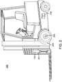
Figure 2 illustrates a perspective view of theforklift 200 for facilitating automation of various tasks within a physical environment according to one or more embodiments of the present invention. - The forklift 200 (i.e., a lift truck, a high/low, a stacker-truck, trailer loader, sideloader or a fork hoist) is a powered industrial truck having various load capacities and used to lift and transport various objects. In some embodiments, the
forklift 200 is configured to move one or more pallets (e.g., thepallets 112 ofFigure 1 ) of units (e.g., theunits 114 ofFigure 1 ) along paths within the physical environment (e.g., thephysical environment 100 ofFigure 1 ). Theforklift 200 may travel inside a storage bay that is multiple pallet positions deep to place or retrieve a pallet. Orientation information (i.e., an entry point orientation) is used to guide theforklift 200 into the storage bay and place the pallet on cantilevered arms or rails. Hence, the dimensions of theforklift 200, including overall width and mast width, must be accurate when determining an orientation associated with an object and/or a target destination. - The
forklift 200 typically includes two or more forks (i.e., skids or tines) for lifting and carrying units within the physical environment. Alternatively, instead of the two or more forks, theforklift 200 may include one or more metal poles (not pictured) in order to lift certain units (e.g., carpet rolls, metal coils and/or the like). In one embodiment, theforklift 200 includes hydraulics-powered, telescopic forks that permit two or more pallets to be placed behind each other without an aisle between these pallets. - The
forklift 200 may further include various mechanic and/or hydraulic components according to one or more embodiments. In some embodiments, theforklift 200 includes one or more hydraulic components (not labeled) that permit lateral and/or rotational movement of two or more forks. In one embodiment, theforklift 200 includes a hydraulic component (not labeled) for moving the forks together and apart. In another embodiment, theforklift 200 includes a mechanical or hydraulic component for squeezing a unit (e.g., barrels, kegs, paper rolls and/or the like) to be transported. In some embodiments, theforklift 200 includes one or more hydraulic components (not labeled) that clamp or squeeze the forks around one or more units (e.g., cartons, boxes, bales and/or the like) in order to lift these units. - The
forklift 200 may be coupled with themobile computer 104, which includes software modules for operating theforklift 200 in accordance with one or more tasks. The task may be created using a prior knowledge of conditions within the physical environment. Theforklift 200 is also coupled with thesensor array 108, which transmits data (e.g., image data, video data, range map data and/or three-dimensional graph data) to themobile computer 104, which stores the sensor array data according to some embodiments. As described in detail further below, thesensor array 108 includes various devices, such as a laser scanner and a camera, for capturing the sensor array data associated with an object load. - The laser scanner and the camera may be mounted to the
forklift 200 exterior. The laser scanner and the camera may articulate or move into various positions along the exterior. For example, the camera and the laser scanner may be attached to one or more forks such that image data and/or laser scanner data is captured moving up and down along with the forks. As another example, the camera and the laser scanner may be attached to a stationary position above or below the forks from which the image data and/or the laser scanner data is recorded depicting a view in front of theforklift 200. The front view may be used to identify obstacles at a target destination along a path and verify clearance after removal of such obstacles. -
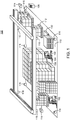
Figure 3 is a schematic of apartial view 202 of theforklift 200 according to one or more embodiments of the present invention. Thepartial view 202 illustrates alift carriage 300 for supporting devices that capture sensor array data as well as lifting elements for engaging object loads according to various embodiments. It is appreciated that the following describes exemplary embodiments of theforklift 200 and the present invention includes other vehicle types and mechanical components. - The
lift carriage 300 is designed to raise and lower one or more lifting elements, such asforks 302, vertically in order to engage and transport object loads. Between theforks 302, ascanner array 321 comprising one ormore laser scanners 304 and one ormore cameras 306 is fitted to the lift carriage 300 (e.g., thesensor array 108 ofFigure 1 ). Thescanner array 321 may be mounted to thelift carriage 300 and retrofit object load sensing to theforklift 200. Because the presence of objects on theforks 302 may obscure the devices, thecamera 306 andlaser 304 may form amoveable sensor head 320 according to one embodiment. When themoveable sensor head 320 is moved into a retracted position, thecamera 306 and thelaser sensor 304 are positioned above theforks 302. Thesensor head 320 is attached to a pair ofguide rails 308, which are attached to the mountingplate 310 through twoguide bushings 312. - As shown in
Figure 3 , thelaser scanner 304 and thecamera 306 may be articulated between multiple positions including, as a minimum, locations above or below theforks 302. In some embodiments, thescanner array 321 includes various mechanical components that articulate (i.e., move)sensor head 320. For example, a ball screw is utilized to raise or lower thelaser scanner 304 and thecamera 306. A type of mechanical components being used for articulation may depend on physical attributes associated with theforklift 200 and/or installation requirements associated with a physical environment. As another example, a driven linear slide table is employed to transport thelaser scanner 304 and thecamera 306 into various positions. - Having the
laser scanner 304 and/or thecamera 306 located in certain positions relative to thelift carriage 300 provides these devices with a clear view beyond any object load being carried on theforks 302. Such positions further enable efficient data fitting between object models and sensor array data, which may be a combination of laser scanner data and image data, as explained further below. When thelaser scanner 304 and thecamera 306 are co-linear as well as orthogonal in the horizontal plane and coplanar in the vertical plane to an automated vehicle axis, various software modules can automatically cross correlate information between these devices, according to some embodiments. In another embodiment, when thelaser scanner 304 and thecamera 306 are not co-linear, the various software modules use geometric transformations to perform the correlation. - Furthermore, the
laser scanner 304 and/or thecamera 306 are used to enhance safety for theforklift 200 by identifying navigational hazards. The laser scanner data indicates locations of various obstructions along a path that are relative to theforklift 200. The identification of these obstructions facilitates path redetermination. Either theforklift 200 is rerouted around the identified obstructions or stopped until the identified obstructions are removed and the path is clear. The integration of thecamera 306 enables environment sensing at theforklift 200. In addition, thelaser scanner 304 and thecamera 306 may operate with a light 318 to enhance obstruction identification. - A
drive motor 314 connected to a gear, which engages a rack in a rack and pinion arrangement and moves thesensor head 320 to a location above theforks 302. Thedrive motor 314, alternatively, positions thesensor head 320 to a location below theforks 302. Thelaser scanner 304, thecamera 306 and thedrive motor 314 are coupled to a mobile computer (e.g., themobile computer 104 ofFigure 1 ). In one or more alternative embodiments, thedriver motor 314 rotates thesensor head 320 when capturing the sensor array data in order to identify objects or object loads that are not directly aligned with theforks 302. Various software modules within the mobile computer control thedrive motor 314 and store image data and laser scanner data. The mobile computer communicates the image data and the laser scanner to a central computer where an object recognition process is executed to identify a particular object and generate orientation information as explained in detail further below. - In some alternative embodiments, the
laser scanner 304 and thecamera 306 may couple with thelift carriage 300 below theforks 302. Such a configuration may be used when approaching a target destination associated with the object load. For example, the target destination includes a rack system, a warehouse floor, a pallet and/or the like. At the location below theforks 302, thelaser scanner 304 and thecamera 306 are capable of capturing data at a warehouse floor level. Hence, thelaser scanner 304 and thecamera 306 provide visibility below any object load being transported by an automated vehicle, such as theforklift 200. - The
laser scanner 304 and thecamera 306 enable obstacle detection at the target destination because mounting these devices below theforks 302 allows various software modules to determine if the target destination is clear of any obstructions before unloading the object load. The various software modules search for such obstructions by examining the sensor array data. If the laser scanner does not detect any points then there are no obstructions above or near the target destination and theforklift 200 can unload the object load successfully. The various software modules may also examine the sensor array data associated with the target destination and determine characteristics regarding the surface on which the object load is to be placed, such as a destination orientation that is relative to thelift carriage 300. -
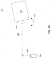
Figures 4A-B diagrammatically illustrate an orientationinformation generation process 400 on one or more object loads 402 according to various embodiments of the present invention.Figure 4A represents a scanning procedure to generate laser scanner data of a horizontal plane (i.e., an x-y plane) comprising theobject load 402.Figure 4B is an image illustrating a vertical plane (i.e., a y-z plane) in front of multiple object loads 402. Eachobject load 402 is stacked on top of anotherobject load 402 and includes thepallet 112 andseveral units 114. The laser scanner data and/or the image are used to determine relative distances from a forklift to the object loads 402. - Various software modules access sensor array data and execute the orientation
information generation process 400 on various objects, such as thepallet 112, to determine an orientation associated with entry points for lifting and transporting the object loads 402. Once the orientationinformation generation process 500 identifies one of the object loads 402, the various software modules generate orientation information associated with entry points to thepallet 112. During the scanning procedure, thelaser scanner 304 captures measurement data across an x-y plane with respect to one or more three-dimensional points on thepallet 112. In some embodiments, thelaser scanner 304 computes distances between theforklift 200 and these points. Thelaser scanner 304 also computes distances between the points themselves. Various software modules correlate the captured data with image data gathered by the camera and apply an object recognition process to identify a matching pallet model. - Once the captured data is normalized with the matching pallet model, the various software modules compute one or more pose or orientation measurements. In some embodiments, the various software modules compute a distance between a pallet edge and a pallet center, which is stored as a
Ty 406. In some embodiments, theTy 406 is a displacement measurement across the y-axis that is relative to a current fork orientation. Thelaser scanner 304 computes a distance to the pallet center, which the various software modules store as aTx 408. In some embodiments, theTx 408 is a displacement measurement between theforklift 200 and theload 404 and may be used to calibrate the camera. - In some embodiments, the various software modules determine a value (e.g., angle of rotation in degrees or radians) that represents angular displacement about the z-axis for the
pallet 112, which is stored asRz 410. TheRz 410 may be determined by fitting the matching pallet model to the captured data in the x-y plane as illustrated inFigure 4A . In some embodiments, the various software modules examine the image data and determine a displacement measurement across the z-axis, which is stored asTz 412. Alternatively, theTz 412 may also be computed by scanning theload 402 while moving the forks and searching for the matching pallet model. The various software modules may also estimate an angular displacement measurement about the y-axis (i.e. Ry) by evaluating laser scans while moving the forks vertically and comparing the laser scanner data with various pallet models and unit models. Alternatively, the angular displacement measurement about the y-axis may be determined from image data for theload 402. - In some embodiments, the various software modules process the image data from the camera and extract various features of the
load 402, such as the entry points of thepallet 112. These features are compared with various object models in order to identify a matching object model, such as a matching pallet model and/or a matching load model. The various object models may be used to train the various software modules to recognize a given object, such as a pallet, a loads and/or a rack system. Alternatively, the various software modules may employ one or more feature extraction procedures, such as line detection, edge detection or gradient processing, to identify the object within an image. -
Figures 5A-B diagrammatically illustrate orientationinformation generation process 500 on arack system 502 according to various embodiments of the present invention.Figure 5A illustrates a scanning process to generate laser scanner data for a horizontal plane (i.e., an x-y plane) comprising therack system 502.Figure 5B is an image illustrating a vertical plane (i.e., a y-z plane) in front of therack system 502. The laser scanner data and/or the image are used to determine relative distances from a forklift to therack system 502. A portion of therack system 502 may be a target destination for an object load (e.g., theobject 402 ofFigure 4 ) as explained further below. - Once an object recognition process identifies the
rack system 502 by comparing rack system models with data captured by thelaser scanner 304 and a camera, various software modules define an entry point orientation associated with ashelf 504 within therack system 502. In some embodiments, the entry point orientation includes numerous measurements indicating angular displacement, such as Ry,Rx 514 andRz 510, and linear displacement, such asTy 508,Tx 506 andTz 512, about the x, y and z-axes. Some of these measurements (e.g., Ry) may be nominal due to structural integrity of therack system 502. On the other hand, the angular displacement measurements may be used to correct for errors in the entry point orientation. - The various software modules cooperate to identify and locate the
shelf 504 in a coordinate system, relative to the automated vehicle, using values for the lineardisplacement measurements Tx 506,Ty 508 andTz 512. The value for theTx 506 may refer to a depth at which an object load is to be placed and/or engaged. The various software modules also cooperate to determine values for the angulardisplacement measurements Rx 514 andRz 510 of theshelf 504. Furthermore, the various software modules determine whether a pallet or another object load is occupying a target destination prior to placing the object load. - As shown in
Figure 5A , thelaser scanner 304 captures the laser scanner data regarding a lift carriage height and vehicle orientation relative to therack system 502 face. The laser scanner data is used to evaluate an entry point orientation of theshelf 504 and position the object load being transported accordingly. In addition to the linear displacement measurements, the laser scanner data includes distances to one or more points on therack system 502 as described in the present disclosure. The various software modules fit a matching rack system model with these distances to compute the value forRz 510. - Then, the various software modules fit the matching rack system against the image as depicted in
Figure 5B to compute the value forRx 514. In one embodiment, feature extraction processing techniques, such as edge detection, may be utilized to identify therack system 502 and compute the various measurements that constitute the entry point orientation of theshelf 504. In some embodiments, the various software modules employ rack system model training to identify therack system 502 and define the entry point orientation associated with theshelf 504. Using rack system model images, the various software modules are trained to determine the linear and angular displacement measurements as explained in the present disclosure. These measurements are subsequently transposed from thelaser scanner 304 origin to the automated vehicle origin. -
Figure 6 is a block diagram of asystem 600 for sensing object load engagement, transportation and disengagement by automated vehicles according to various embodiments of the present invention. In some embodiments, thesystem 600 includes themobile computer 104, thecentral computer 106 and thesensor array 108 in which each component is coupled to each other through anetwork 602. - The
mobile computer 104 is a type of computing device (e.g., a laptop, a desktop, a Personal Desk Assistant (PDA) and the like) that comprises a central processing unit (CPU) 604,various support circuits 606 and amemory 608. TheCPU 604 may comprise one or more commercially available microprocessors or microcontrollers that facilitate data processing and storage.Various support circuits 606 facilitate operation of theCPU 604 and may include clock circuits, buses, power supplies, input/output circuits and/or the like. Thememory 608 includes a read only memory, random access memory, disk drive storage, optical storage, removable storage, and the like. Thememory 608 includes various data, such assensor array data 610. Thememory 608 includes various software packages, such asautomated vehicle software 612 for controlling the movement of an automated vehicle, for example a forklift, and storing laser scanner data and image data as thesensor array data 108. - The
central computer 106 is a type of computing device (e.g., a laptop computer, a desktop computer, a Personal Desk Assistant (PDA) and the like) that comprises a central processing unit (CPU) 616,various support circuits 618 and amemory 620. TheCPU 616 may comprise one or more commercially available microprocessors or microcontrollers that facilitate data processing and storage.Various support circuits 618 facilitate operation of theCPU 616 and may include clock circuits, buses, power supplies, input/output circuits and/or the like. Thememory 620 includes a read only memory, random access memory, disk drive storage, optical storage, removable storage, and the like. Thememory 620 includes various data, such asmodel information 622 andorientation information 624. Thememory 620 includes various software packages, such as amanager 626, anobject recognition process 628 and anenvironment sensing module 630. - The
manager 626 includes software code (e.g., processor executable instructions) that is configured to instruct the automated vehicle, such as the forklift, to execute each and every task, for example transporting object loads. In some embodiments, themanager 626 uses theenvironment sensing module 630 to identify a particular object load. Such an object load may be manually placed within an industrial environment. Themanager 626 generatespath information 632 to the particular object load and a target destination. Themanager 626 communicates thepath information 632 to theautomated vehicle software 612, which moves the automated vehicle along the designated path. - In some embodiments, the
manager 626 implements a finer level of control over automated vehicle operation. For example, themanager 626 may instruct theautomated vehicle software 612 to engage an unstable object load, such as a broken pallet or obstructed entry points. Themanager 626 instructs theenvironment sensing module 626 to continuously generate theorientation information 624 during which theautomated vehicle software 612 adjusts lifting element positions. - The
network 602 comprises a communication system that connects computers by wire, cable, fiber optic, and/or wireless links facilitated by various types of well-known network elements, such as hubs, switches, routers, and the like. Thenetwork 602 may employ various well-known protocols to communicate information amongst the network resources. For example, thenetwork 602 may be part of the Internet or intranet using various communications infrastructure such as Ethernet, WiFi, WiMax, General Packet Radio Service (GPRS), and the like. - In some embodiments, the
model information 622 indicates attributes associated with various types of warehouse structures, such as units, pallets, rack systems, conveyers and object loads (e.g., a pallet supporting one or more units). Themodel information 622 may include dimensions (e.g., a size and/or a shape), a type and an ISO standard version associated with a particular pallet, object or rack system. For example, themodel information 622 associated with the particular pallet may include a pallet type (e.g., stringer, block and/or the like), a corresponding ISO standard (e.g., the ISO Standard 6780), length/width measurements as well as locations of entry points (i.e., apertures) intended for forklift engagement. - The
sensor array 108 is communicable coupled to themobile computer 104, which is attached to an automated vehicle, such as a forklift (e.g., theforklift 200 ofFigure 2 ). Thesensor array 108 includes a plurality ofdevices 614 for monitoring a physical environment and capturing data associated with various objects, which is stored by themobile computer 104 as thesensor array data 610. In some embodiments, thesensor array 108 may include any combination of one or more laser scanners and/or one or more cameras. In some embodiments, the plurality ofdevices 614 may be mounted to the automated vehicle. For example, a laser scanner and a camera may be attached to a lift carriage at a position above the forks. Alternatively, the laser scanner and the camera may be located below the forks. The plurality ofdevices 614 may also be distributed throughout the physical environment at fixed positions. - In some embodiments, the
sensor array data 610 includes an aggregation of data transmitted by the plurality ofdevices 614. In one embodiment, the one or more cameras transmit image data and/or video data of the physical environment that are relative to a vehicle. In another embodiment, the one or more laser scanners (e.g., three-dimensional laser scanners) analyze objects within the physical environment and capture data relating to various physical attributes, such as size and shape. The captured data can then be compared with three-dimensional object models. The laser scanner creates a point cloud of geometric samples on the surface of the subject. These points can then be used to extrapolate the shape of the subject (i.e., reconstruction). The laser scanners have a cone-shaped field of view. While the cameras record color information associated with object surfaces within each and every field of views, the laser scanners record distance information about these object surfaces. - The data produced by the laser scanner indicates a distance to each point on each object surface. Based on these distances, the
object recognition process 628 determines a three dimensional position of the each point in a local coordinate system relative to each laser scanner. Theenvironment sensing module 630 transposes each three-dimensional position to be relative to the vehicle. The laser scanners perform multiple scans from different perspectives in order to determine the points on the each and every object surface. Theobject recognition process 628 normalizes the data produced by the multiple scans by aligning the distances along a common reference system. Then, these software modules merge the object surfaces to create a model of the objects within a partial field of view. - The
environment sensing module 630 includes software code (e.g., processor-executable instructions) for generating theorientation information 624 according to various embodiments. As described in the present disclosure, theorientation information 624 includes various measurements indicating angular and linear displacement about the x, y and z-axes of certain objects. In some embodiments, theenvironment sensing module 630 may define an entry point orientation associated with a pallet or a rack system shelf. In another embodiment, theenvironment sensing module 630 may define a destination orientation associated with a target destination of an object load. Theenvironment sensing module 630 instructs theautomated vehicle software 612 to position one or more lifting elements in accordance with theorientation information 624. On a forklift, for example, theenvironment sensing module 630 may position two forks using the various measurements. - Alternatively, the
environment sensing module 630 communicates theorientation information 624 to themobile computer 104 in order to provide feedback for a human operation. In some embodiments, themobile computer 104 presents a location of the object load within the physical environment as well as the entry point orientation. For example, the human operator may incorrectly gauge the object load orientation when placed at a considerable height. Using manual controls, the human operator positions one or more lifting elements accordingly. Theenvironment sensing module 624 recognizes such a human error and responds by communicating a correct entry point orientation. Subsequently, the human operator repositions the one or more lifting elements and engages the object load. In some embodiments, theautomated vehicle software 612 automatically repositions the one or more lifting elements in response to the incorrect object load orientation. Thus, theorientation information 624 serves to rectify incorrect object load orientations and guide the human operator. -
Figure 7 is a functional block diagram that illustrates atask automation system 700 using orientation information according to various embodiments of the present invention. - The
task automation system 700 utilizes a sensor array that includes various devices for capturing data associated with one or more objects. In some embodiments, thetask automation system 700 employs device drivers for accessing and communicating the captured data from the various devices. For example, theenvironment sensing module 630 invokes acamera driver 702 and alaser scanner driver 704 for the purpose of capturing image/video data and laser scanner data, respectively. The image/video data and the laser scanner data are processed by theenvironment sensing module 630, which computes various orientation or pose measurements and then, communicates such information to theautomated vehicle software 612. Any required dimensions of an object, such as a pallet, or barcode types are recorded in themodel information 622. - In some embodiments, the
environment sensing module 630 includes anobstacle detection module 706 and a segmentation andfeature matching module 708. The segmentation andfeature matching module 708 includes theobject recognition process 628, a labelposition detection module 710 and anorientation detection module 712. The labelposition detection module 710 includes software code (e.g., processor-executable instructions) for examining image data for a barcode or a label. Theorientation detection module 712 includes software code (e.g., processor-executable instructions) that is configured to determine a relative pose associated with an object load (i.e., one or more products) and examine a target destination for obstacles. Theorientation detection module 712 also determines if the object load is correctly placed on the forks. -
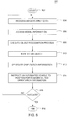
Figure 8 is a flow diagram of amethod 800 for sensing object load engagement, transportation and disengagement by automated vehicles according to various embodiments of the present invention. An environment sensing module within a central computer performs themethod 800 according to some embodiments. Themethod 800 starts atstep 802 and proceeds to step 804. - At
step 804, sensor array data is processed. As explained in the present disclosure, a sensor array (e.g., thesensor array 108 ofFigure 1 and/or thesensor head 320 ofFigure 3 ) includes various devices, such as a laser scanner and/or a camera, for capturing data associated with various objects. These devices transmit image data and/or laser scanner data, which is stored in a mobile computer as the sensor array data (e.g., thesensor array data 610 ofFigure 6 ) according to some embodiments. The environment sensing module accesses the sensor array data within the mobile computer. Atstep 806, model information is accessed. The model information (e.g., themodel information 622 ofFigure 6 ) may include a database maintaining physical attributes (e.g., dimensions, shapes and/or the like) associated with various object models, such as pallet models, load models, rack system models and/or the like. The model information is stored in the central computer and accessed by the environment sensing module. - At
step 808, an object recognition process is executed. Various software modules, such as the environment sensing module (e.g., theenvironment sensing module 630 ofFigure 6 ), perform the object recognition process (e.g., theobject recognition process 628 ofFigure 6 ) by comparing the sensor array data with the various object models as described in the present disclosure. For example, the object recognition process may search for an object model, such as a pallet model, having similar or identical dimensions (e.g., length and width of entry points) as a particular object, such as a pallet (e.g., thepallet 112 ofFigure 1 ). As another example, the object recognition process may utilize feature extraction processing techniques, such as edge detection, to identify the particular object, such as a rack system. - At
step 810, an object is identified. By correlating the laser scanner data with the image data, the object recognition process identifies an object model matching the object being analyzed. Atstep 812, orientation information is generated. Once the object recognition process identifies a matching object model, such as a matching pallet model, an environment sensing module (e.g., theenvironment sensing module 630 ofFigure 6 ) fits the matching object model against the sensor array data and computes various pose or orientation measurements as explained in the present disclosure. - At
step 814, an automated vehicle is instructed to position one or more lifting elements, such as one or more forks (e.g., theforks 302 ofFigure 3 ), based on the orientation information. In some embodiments, the environment sensing module communicates the orientation information to the automated vehicle software, which directs the lifting elements to a position defined by the orientation measurements. The environment sensing module instructs the automated vehicle software (e.g., theautomated vehicle software 612 ofFigure 6 ) to move the forks into an orientation that is optimal for engaging the particular object, such as a pallet, and/or placing the object load at the target destination. Atstep 816, themethod 800 ends. -
Figure 9 is a flow diagram of amethod 900 for positioning lifting elements within an automated vehicle based on orientation information according to one or more embodiments. Themethod 900 may be performed by the automated vehicle software within a mobile computer. - The
method 900 starts atstep 902 and proceeds to step 904. Atstep 904, orientation information and path information are received. In some embodiments, the path information is used to perform a task, such as engaging and transporting an object load. For example, the automated vehicle software receives a first path to a pallet (e.g., thepallet 112 ofFigure 1 ) having a plurality of units (e.g., the plurality ofunits 114 ofFigure 1 ) as well as a second path from the pallet to a target destination. As such, the automated vehicle software moves an automated vehicle along the first path, engages the pallet and then, moves to the target destination along the second path. - At
step 906, entry point orientation measurements associated with the object load are accessed. In some embodiments, the orientation information (e.g., the orientation information 324 ofFigure 3 ) includes various linear and angular displacement measurements between the automated vehicle (e.g., theforklift 200 ofFigure 2 ) and the object load (e.g., theobject load 402 ofFigure 4 ). Atstep 908, lifting elements are moved in accordance with the entry point orientation measurements. For example, the automated vehicle software positions the lifting elements into an orientation that matches the entry point orientation measurements as explained in the present disclosure. Atstep 910, the object load is engaged. - At
step 912, the object load is transported to a destination. For example, the automated vehicle lifts and transports the pallet supporting several units to a target destination, such as a rack system shelf or another pallet. Using the path information, the automated vehicle software moves the automated vehicle to the target destination. Atstep 914, destination orientation measurements are accessed. Atstep 916, the lifting elements are moved in accordance with the destination orientation measurements. Atstep 918, the object load is placed at the destination. Atstep 920, the method ends. -
Figure 10 is a flow diagram of amethod 1000 for performing a task using an environment sensing module according to various embodiments. Themethod 1000 may be performed by a manager (e.g., themanager 626 ofFigure 6 ) within a central computer (e.g., thecentral computer 106 ofFigure 1 ). - The
method 1000 starts atstep 1002 and proceeds to step 1004. Atstep 1004, a task is received. For example, the manager may be instructed to find and move an object load (e.g., theobject load 402 ofFigure 4 ) to a target destination. Atstep 1006, an environment sensing module is instructed to locate and identify the object load. The environment sensing module (e.g., theenvironment sensing module 630 ofFigure 3 ) applies image processing techniques on images of the industrial environment to identify the object load. For example, the environment sensing module may combine consecutive images to identify three-dimensional objects within a camera field of view. Alternatively, the environment sensing module may employ a barcode or a radio frequency identification (RFID) reader (e.g., thedevice 618 ofFigure 3 ) to identify the object load. - At
step 1008, a path for performing the task is generated. Atstep 1010, an automated vehicle is instructed to move along the path. In some embodiments, the manager communicates the path to automated vehicle software (e.g., theautomated vehicle software 616 ofFigure 6 ), which controls automated vehicle steering. Atstep 1012, a determination is made as to whether the automated vehicle successfully performed the task. The automated vehicle software returns indicia of the automated vehicle performance. The manager processes the indicia and determines whether the automated vehicle successfully completed the given task. If the automated vehicle successfully performed the given task, themethod 1000 proceeds to step 1014. Atstep 1014, the method ends. If, on the other hand, the automated vehicle did not successfully perform the given task, themethod 1000 returns to step 1004. - While the foregoing is directed to embodiments of the present invention, other and further embodiments of the invention may be devised without departing from the basic scope thereof, and the scope thereof is determined by the claims that follow.
Claims (15)
- A method of operating an automated vehicle (102) to engage or disengage an object load (402) in a physical environment comprising a rack system (502), the method comprising:analysing a plurality of objects that are placed throughout the physical environment by processing data that is transmitted from a sensor array (108) attached to a lift carriage (300) of the vehicle (102);characterised in that the method further comprises:executing an object recognition process (628) on the sensor array data (610) to identify the rack system (502) by comparing rack system models with the sensor array data (610);utilising the rack system identification and a software module resident on a mobile computer (104) coupled to the vehicle (102) or a central computer (106) coupled to the sensor array (108) via a network (602) to align a lifting element (302) of the vehicle (102) with entry points for a pallet (112) or a shelf (504) within the rack system (502); andengaging or disengaging the object load (402) with the aligned lifting element (302).
- The method of claim 1 wherein:the vehicle (102) comprises lifting forks (302) and the sensor array (108) is positioned below the lifting forks (302); andthe method comprises utilising a software module resident on a mobile computer (104) coupled to the vehicle (102) or a central computer (106) coupled to the sensor array (108) via a network (602) to determine if the target destination is clear of obstructions and disengaging the object load (402) if the target destination is clear of obstructions.
- The method of claim 1 wherein the method comprises:engaging an object load (402); andutilising a software module resident on a mobile computer (104) coupled to the vehicle (102) or a central computer (106) coupled to the sensor array (108) via a network (602) to compute a distance to a centre of the engaged object load (402); andusing the computed distance to a centre of the engaged object load (402) and a stored displacement measurement between the vehicle (102) and the engaged object load (402) to calibrate the sensor array (108).
- The method of claim 1 wherein the method further comprises:scanning the object load (402) while moving the lift carriage (300) and the sensor array (108) vertically;executing an object recognition process (628) on the sensor array data (610) to identify a matching pallet model;engaging or disengaging the object load (402) based on the identification of the matching pallet model.
- The method of claim 1 wherein the method further comprises utilising a software module resident on a mobile computer (104) coupled to the vehicle (102) or a central computer (106) coupled to the sensor array (108) via a network (602) to define an entry point orientation associated with a shelf (504) within the rack system (502).
- The method of claim 1 wherein:the sensor array (108) comprises a camera (306) attached to the lift carriage (300) of the vehicle (102); andthe sensor array data (610) comprises data captured by the camera (306).
- The method of claim 1 wherein:the sensor array (108) comprises a laser scanner (304) and a camera (306) attached to the lift carriage (300) of the vehicle (102); andthe sensor array data (610) comprises data captured by the laser scanner (304) and the camera (306).
- The method of claim 7 wherein the laser scanner (304) and the camera (306) operate with a light (318) to enhance obstruction identification.
- The method of claim 1 wherein the sensor array (108) comprises a laser scanner (304) and a camera (306) attached to the lift carriage (300) of the vehicle (102) as a moveable sensor head (320) attached to a pair of guide rails (308).
- The method of claim 9 wherein a ball screw is utilised to raise or lower the sensor head (320) or a driven linear slide table is employed to transport the sensor head (320).
- The method of claim 9 wherein:the vehicle (102) comprises lifting forks (302) and a drive motor (314) connected to a gear, which engages a rack in a rack and pinion arrangement; andthe method comprises utilising the rack and pinion arrangement to move the sensor head (320) to a location above the lifting forks (302), below the lifting forks (302).
- The method of claim 11 wherein the method comprises rotating the sensor head (320) with the drive motor (314) when capturing the sensor array data (610) in order to identify objects or object loads (402) that are not directly aligned with the forks (302).
- The method of claim 1 wherein:the sensor array (108) comprises a laser scanner (304) and a camera (306) attached to the lift carriage (300) of the vehicle (102);the laser scanner (304) and the camera (306) are co-linear and orthogonal in the horizontal plane and coplanar in the vertical plane to an automated vehicle axis; andthe method comprises using a software module resident on a mobile computer (104) coupled to the vehicle (102) or a central computer (106) coupled to the sensor array (108) via a network (602) to automatically cross correlate information between the laser scanner (304) and the camera (306).
- The method of claim 1 wherein:the sensor array (108) comprises a laser scanner (304) and a camera (306) attached to the lift carriage (300) of the vehicle (102);the method comprises using a software module resident on a mobile computer (104) coupled to the vehicle (102) or a central computer (106) coupled to the sensor array (108) via a network (602) to use geometric transforms to cross correlate information between the laser scanner (304) and the camera (306).
- A system for operating an automated vehicle (102) to engage or disengage an object load (402) in a physical environment comprising a rack, the system comprising a mobile computer (104) coupled to the vehicle (102), a central computer (106), and a sensor array (108) attached to a lift carriage (300) of the vehicle (102), wherein:the mobile computer (104), the central computer (106), and the sensor array (108) are coupled to each other through a network (602); andcharacterised in that software modules within the central computer (106), the mobile computer (104), or both, process data that are transmitted from the sensor array (108) to facilitate object load (402) engagement or disengagement by:executing an object recognition process (628) on the sensor array data (610) to identify the rack system (502) by comparing rack system models with the sensor array data (610),utilising the rack system identification and a software module resident on a mobile computer (104) coupled to the vehicle (102) or a central computer (106) coupled to the sensor array (108) via a network (602) to align a lifting element (302) of the vehicle (102) with entry points for a pallet (112) or a shelf (504) within the rack system (502), andengaging or disengaging the object load (402) with the aligned lifting element (302).
Applications Claiming Priority (2)
| Application Number | Priority Date | Filing Date | Title |
|---|---|---|---|
| US12/718,620 US8538577B2 (en) | 2010-03-05 | 2010-03-05 | Method and apparatus for sensing object load engagement, transportation and disengagement by automated vehicles |
| PCT/NZ2011/000024 WO2011108944A2 (en) | 2010-03-05 | 2011-02-17 | Method and apparatus for sensing object load engagement, transportation and disengagement by automated vehicles |
Publications (3)
| Publication Number | Publication Date |
|---|---|
| EP2542496A2 EP2542496A2 (en) | 2013-01-09 |
| EP2542496A4 EP2542496A4 (en) | 2016-06-15 |
| EP2542496B1 true EP2542496B1 (en) | 2018-05-23 |
Family
ID=44532020
Family Applications (1)
| Application Number | Title | Priority Date | Filing Date |
|---|---|---|---|
| EP11750973.7A Active EP2542496B1 (en) | 2010-03-05 | 2011-02-17 | Method and system for sensing object load engagement and disengagement by automated vehicles |
Country Status (5)
| Country | Link |
|---|---|
| US (1) | US8538577B2 (en) |
| EP (1) | EP2542496B1 (en) |
| AU (1) | AU2011221652B2 (en) |
| CA (1) | CA2791842C (en) |
| WO (1) | WO2011108944A2 (en) |
Families Citing this family (56)
| Publication number | Priority date | Publication date | Assignee | Title |
|---|---|---|---|---|
| US8829020B2 (en) | 2009-07-16 | 2014-09-09 | Mallinckrodt Llc | Compounds and compositions for use in phototherapy and in treatment of ocular neovascular disease and cancers |
| JP5503419B2 (en) * | 2010-06-03 | 2014-05-28 | 株式会社日立製作所 | Automated guided vehicle and travel control method |
| CN102583194B (en) * | 2011-01-04 | 2014-03-26 | 瀚宇彩晶股份有限公司 | Stacking machine providing transport information according to weight of cargos and relevant method thereof |
| EP2668623A2 (en) * | 2011-01-24 | 2013-12-04 | Sky-Trax, Inc. | Inferential load tracking |
| KR102041093B1 (en) | 2011-04-11 | 2019-11-06 | 크라운 이큅먼트 코포레이션 | Method and apparatus for efficient scheduling for multiple automated non-holonomic vehicles using a coordinated path planner |
| US8655588B2 (en) | 2011-05-26 | 2014-02-18 | Crown Equipment Limited | Method and apparatus for providing accurate localization for an industrial vehicle |
| US8548671B2 (en) | 2011-06-06 | 2013-10-01 | Crown Equipment Limited | Method and apparatus for automatically calibrating vehicle parameters |
| US20140058634A1 (en) | 2012-08-24 | 2014-02-27 | Crown Equipment Limited | Method and apparatus for using unique landmarks to locate industrial vehicles at start-up |
| US9056754B2 (en) | 2011-09-07 | 2015-06-16 | Crown Equipment Limited | Method and apparatus for using pre-positioned objects to localize an industrial vehicle |
| EP2768758B1 (en) | 2011-10-19 | 2018-09-05 | Crown Equipment Corporation | Identifying, matching and tracking multiple objects in a sequence of images |
| BR112014019924B1 (en) * | 2012-02-17 | 2022-02-15 | Columbus Mckinnon Corporation | MATERIAL HANDLING SYSTEM, AND, METHOD OF MONITORING A MATERIAL HANDLING SYSTEM |
| US10216865B1 (en) * | 2012-03-06 | 2019-02-26 | Vecna Robotics, Inc. | Monitoring one or more articles on a support surface |
| US10028878B1 (en) | 2012-11-28 | 2018-07-24 | Vecna Technologies, Inc. | Body worn apparatus |
| US9415983B2 (en) * | 2012-12-17 | 2016-08-16 | Shamrock Foods Company | Crash prevention system for a storage and retrieval machine |
| NL2011132C2 (en) * | 2013-07-10 | 2015-01-13 | Stertil Bv | Lifting system for lifting a vehicle and method for operating the lifting system. |
| US9354070B2 (en) | 2013-10-31 | 2016-05-31 | Crown Equipment Corporation | Systems, methods, and industrial vehicles for determining the visibility of features |
| US20150269501A1 (en) * | 2014-03-18 | 2015-09-24 | Ghostruck Co | System and process for resource allocation to relocate physical objects |
| EP3194324A1 (en) | 2014-09-15 | 2017-07-26 | Crown Equipment Corporation | Lift truck with optical load sensing structure |
| EP3000771B1 (en) * | 2014-09-25 | 2017-11-22 | Toyota Material Handling Manufacturing Sweden AB | Fork-lift truck |
| US9734639B2 (en) * | 2014-12-31 | 2017-08-15 | Hand Held Products, Inc. | System and method for monitoring an industrial vehicle |
| US20180099846A1 (en) | 2015-03-06 | 2018-04-12 | Wal-Mart Stores, Inc. | Method and apparatus for transporting a plurality of stacked motorized transport units |
| US20160259344A1 (en) | 2015-03-06 | 2016-09-08 | Wal-Mart Stores, Inc. | Shopping facility assistance systems, devices, and methods to facilitate responding to a user's request for product pricing information |
| WO2016142794A1 (en) | 2015-03-06 | 2016-09-15 | Wal-Mart Stores, Inc | Item monitoring system and method |
| US12084824B2 (en) | 2015-03-06 | 2024-09-10 | Walmart Apollo, Llc | Shopping facility assistance systems, devices and methods |
| EP3283358B1 (en) * | 2015-04-15 | 2021-06-02 | Volvo Truck Corporation | Vehicle guidance system |
| JP6469506B2 (en) * | 2015-04-16 | 2019-02-13 | 株式会社豊田中央研究所 | forklift |
| JP6542574B2 (en) * | 2015-05-12 | 2019-07-10 | 株式会社豊田中央研究所 | forklift |
| US10005587B2 (en) | 2015-07-08 | 2018-06-26 | Divert, Inc. | Forklift system for waste or recyclable material handling |
| US20180203471A1 (en) * | 2015-07-16 | 2018-07-19 | Sikorsky Aircraft Corporation | Clearance sensor system |
| CN105502226A (en) * | 2016-01-26 | 2016-04-20 | 东莞双成电子塑胶有限公司 | Fork laser positioning auxiliary device of forklift truck |
| CA2961938A1 (en) | 2016-04-01 | 2017-10-01 | Wal-Mart Stores, Inc. | Systems and methods for moving pallets via unmanned motorized unit-guided forklifts |
| US9990535B2 (en) | 2016-04-27 | 2018-06-05 | Crown Equipment Corporation | Pallet detection using units of physical length |
| BR112018074419A2 (en) * | 2016-06-24 | 2019-03-06 | Crown Equipment Corporation | computer-implemented process and system for indirectly tracking electronic stamps. |
| JP6451715B2 (en) | 2016-10-14 | 2019-01-16 | 株式会社豊田自動織機 | forklift |
| US10048398B2 (en) * | 2016-10-31 | 2018-08-14 | X Development Llc | Methods and systems for pallet detection |
| US10328578B2 (en) | 2017-04-21 | 2019-06-25 | X Development Llc | Methods and systems for detecting, recognizing, and localizing pallets |
| US10538421B2 (en) * | 2017-05-05 | 2020-01-21 | Atlantic Corporation | Systems, devices, and methods for inventory management of carpet rolls in a warehouse |
| US10655945B2 (en) * | 2017-07-19 | 2020-05-19 | Symbol Technologies, Llc | Methods and apparatus to coordinate movement of automated vehicles and freight dimensioning components |
| US10394234B2 (en) * | 2017-12-18 | 2019-08-27 | The Boeing Company | Multi-sensor safe path system for autonomous vehicles |
| US11416001B2 (en) | 2018-07-17 | 2022-08-16 | Crown Equipment Corporation | Systems and methods for vehicle position calibration using rack leg identification |
| US11379788B1 (en) | 2018-10-09 | 2022-07-05 | Fida, Llc | Multilayered method and apparatus to facilitate the accurate calculation of freight density, area, and classification and provide recommendations to optimize shipping efficiency |
| US10369701B1 (en) | 2018-10-30 | 2019-08-06 | Mujin, Inc. | Automated package registration systems, devices, and methods |
| KR102650494B1 (en) | 2018-10-30 | 2024-03-22 | 무진 아이엔씨 | Automated package registration systems, devices, and methods |
| AU2020219110A1 (en) | 2019-02-06 | 2021-08-26 | Crown Equipment Corporation | Systems and methods for end of aisle protection and vehicle position calibration using rack leg identification |
| CN109987550B (en) * | 2019-04-04 | 2021-03-19 | 北京极智嘉科技有限公司 | Calibration method and storage medium for high-position forklift and returning storage container |
| US11958687B2 (en) | 2019-04-02 | 2024-04-16 | Beijing Geekplus Technology Co. Ltd | High-position robot, method for calibrating return of storage container, and storage medium |
| US11591197B2 (en) | 2019-04-05 | 2023-02-28 | The Raymond Corporation | Load handling module for a material handling vehicle |
| BR112021020336A2 (en) * | 2019-04-08 | 2021-12-14 | Lineage Logistics Llc | Automatic transport of pallets of goods |
| EP4031861A4 (en) | 2019-09-18 | 2023-07-19 | Divert, Inc. | Systems and methods for tracking product environment throughout a supply chain |
| DE102020105215A1 (en) * | 2020-02-27 | 2021-09-02 | Jungheinrich Aktiengesellschaft | Method for calibrating a sensor unit of an industrial truck |
| DE102021001282A1 (en) | 2020-04-01 | 2021-10-07 | Sew-Eurodrive Gmbh & Co Kg | Mobile system and method for operating a mobile system |
| CA3187675A1 (en) * | 2020-09-30 | 2022-04-07 | Chun Zhang | Vehicle object-engagement scanning system and method |
| WO2023230330A1 (en) * | 2022-05-27 | 2023-11-30 | Seegrid Corporation | System and method for performing interactions with physical objects based on fusion of multiple sensors |
| US20230400858A1 (en) * | 2022-06-10 | 2023-12-14 | Autoguide, LLC | Identifying transport structures |
| FR3137031A1 (en) * | 2022-06-22 | 2023-12-29 | Compagnie Generale Des Etablissements Michelin | Autonomous load transport forklift and associated method |
| FR3137077A1 (en) * | 2022-06-22 | 2023-12-29 | Compagnie Generale Des Etablissements Michelin | Autonomous forklift for lifting and transporting loads, and associated method |
Family Cites Families (77)
| Publication number | Priority date | Publication date | Assignee | Title |
|---|---|---|---|---|
| JPS6067818A (en) | 1983-09-22 | 1985-04-18 | Hitachi Ltd | On-vehicle navigator |
| US4855915A (en) * | 1987-03-13 | 1989-08-08 | Dallaire Rodney J | Autoguided vehicle using reflective materials |
| US4858132A (en) * | 1987-09-11 | 1989-08-15 | Ndc Technologies, Inc. | Optical navigation system for an automatic guided vehicle, and method |
| US5011358A (en) * | 1988-10-25 | 1991-04-30 | Andersen Eric T | Height indicator for a fork lift truck |
| US5179329A (en) * | 1989-04-25 | 1993-01-12 | Shinko Electric Co., Ltd. | Travel control method, travel control device, and mobile robot for mobile robot systems |
| US5051906A (en) * | 1989-06-07 | 1991-09-24 | Transitions Research Corporation | Mobile robot navigation employing retroreflective ceiling features |
| US5956250A (en) * | 1990-02-05 | 1999-09-21 | Caterpillar Inc. | Apparatus and method for autonomous vehicle navigation using absolute data |
| US5170352A (en) * | 1990-05-07 | 1992-12-08 | Fmc Corporation | Multi-purpose autonomous vehicle with path plotting |
| US5202832A (en) * | 1991-01-29 | 1993-04-13 | R. R. Donnelley & Sons Co. | Material handling automation system using portable transfer module |
| US5258911A (en) | 1991-04-09 | 1993-11-02 | Crown Equipment Corporation | End of aisle control system |
| US5491670A (en) * | 1993-01-21 | 1996-02-13 | Weber; T. Jerome | System and method for sonic positioning |
| US5539638A (en) * | 1993-08-05 | 1996-07-23 | Pavilion Technologies, Inc. | Virtual emissions monitor for automobile |
| US5471393A (en) * | 1994-01-26 | 1995-11-28 | Bolger; Joe | Driver's associate: a system for vehicle navigation and driving assistance |
| US5961571A (en) * | 1994-12-27 | 1999-10-05 | Siemens Corporated Research, Inc | Method and apparatus for automatically tracking the location of vehicles |
| US5916285A (en) * | 1995-10-18 | 1999-06-29 | Jervis B. Webb Company | Method and apparatus for sensing forward, reverse and lateral motion of a driverless vehicle |
| DE19613386A1 (en) * | 1996-04-03 | 1997-10-09 | Fiat Om Carrelli Elevatori | Industrial truck, which can be operated either manually or automatically |
| SE9601440D0 (en) * | 1996-04-15 | 1996-04-15 | Apogeum Ab | Method for determining a plurality of fixed objects |
| US6092010A (en) * | 1997-09-03 | 2000-07-18 | Jervis B. Webb Company | Method and system for describing, generating and checking non-wire guidepaths for automatic guided vehicles |
| SE511504C2 (en) * | 1997-10-17 | 1999-10-11 | Apogeum Ab | Method and apparatus for associating anonymous reflectors to detected angular positions |
| DE19757333C1 (en) | 1997-12-22 | 1999-09-16 | Litef Gmbh | Automatic, fast calibration of an on-board measurement of a speed vector |
| JPH11296229A (en) * | 1998-02-13 | 1999-10-29 | Komatsu Ltd | Vehicle guide device |
| JP3316841B2 (en) * | 1998-08-06 | 2002-08-19 | 村田機械株式会社 | Automatic guided vehicle system |
| JP3316842B2 (en) * | 1998-08-06 | 2002-08-19 | 村田機械株式会社 | Automatic guided vehicle system and automatic guided vehicle guidance method |
| US7123166B1 (en) * | 2000-11-17 | 2006-10-17 | Haynes Michael N | Method for managing a parking lot |
| JP2002048579A (en) | 2000-04-28 | 2002-02-15 | Matsushita Electric Ind Co Ltd | Communication type navigation system |
| US6917839B2 (en) * | 2000-06-09 | 2005-07-12 | Intellectual Assets Llc | Surveillance system and method having an operating mode partitioned fault classification model |
| JP2002108446A (en) | 2000-09-29 | 2002-04-10 | Nippon Seiki Co Ltd | Method for guiding traveling object |
| US6428439B1 (en) * | 2000-10-04 | 2002-08-06 | Gkn Automotive, Inc. | Integrated viscous transmission in a differential |
| US6952488B2 (en) * | 2001-08-27 | 2005-10-04 | Carnegie Mellon University | System and method for object localization |
| US6669089B2 (en) | 2001-11-12 | 2003-12-30 | 3M Innovative Properties Co | Radio frequency identification systems for asset tracking |
| JP3968501B2 (en) * | 2001-11-30 | 2007-08-29 | ソニー株式会社 | Robot self-position identification system and self-position identification method |
| US7844364B2 (en) * | 2002-04-16 | 2010-11-30 | Irobot Corporation | Systems and methods for dispersing and clustering a plurality of robotic devices |
| AU2003223091A1 (en) * | 2002-04-30 | 2003-11-17 | Telmap Ltd. | Dynamic navigation system |
| US20050149256A1 (en) * | 2002-05-10 | 2005-07-07 | Siemens Aktiengesellschaft | Device for determining the position by means of fixed and/or variable landmarks |
| DE10220936A1 (en) | 2002-05-10 | 2003-12-04 | Siemens Ag | Localization device with fixed and / or variable landmarks |
| GB2389947B (en) | 2002-07-25 | 2004-06-02 | Golden River Traffic Ltd | Automatic validation of sensing devices |
| DE10234730A1 (en) | 2002-07-30 | 2004-02-19 | Josef Schreiner | Position determination method for use with industrial trucks, e.g. forklift trucks, within a defined area, wherein the positions of transport and reference fixed objects are known and truck positions are determined from them |
| US7272467B2 (en) * | 2002-12-17 | 2007-09-18 | Evolution Robotics, Inc. | Systems and methods for filtering potentially unreliable visual data for visual simultaneous localization and mapping |
| KR100506533B1 (en) * | 2003-01-11 | 2005-08-05 | 삼성전자주식회사 | Mobile robot and autonomic traveling system and method thereof |
| DE10323641A1 (en) * | 2003-05-26 | 2005-01-05 | Daimlerchrysler Ag | Movable sensor device on the load means of a forklift |
| JP4409904B2 (en) | 2003-10-08 | 2010-02-03 | 株式会社日立製作所 | Route information providing system and route information providing method |
| DE102004001197A1 (en) | 2004-01-07 | 2005-08-04 | Daimlerchrysler Ag | Automatically controlled fork lift truck in a production plant uses vision system for object recognition followed by automatic handling |
| US7689321B2 (en) * | 2004-02-13 | 2010-03-30 | Evolution Robotics, Inc. | Robust sensor fusion for mapping and localization in a simultaneous localization and mapping (SLAM) system |
| US8280398B2 (en) | 2004-03-03 | 2012-10-02 | Nec Corporation | Positioning system, positioning method, and program thereof |
| KR100571837B1 (en) * | 2004-03-05 | 2006-04-17 | 삼성전자주식회사 | Method and apparatus for controlling navigation in automatic navigation vehicle |
| US7148458B2 (en) * | 2004-03-29 | 2006-12-12 | Evolution Robotics, Inc. | Circuit for estimating position and orientation of a mobile object |
| JP2007530978A (en) * | 2004-03-29 | 2007-11-01 | エヴォリューション ロボティクス インコーポレイテッド | Position estimation method and apparatus using reflected light source |
| KR100703692B1 (en) * | 2004-11-03 | 2007-04-05 | 삼성전자주식회사 | System, apparatus and method for improving readability of a map representing objects in space |
| US20100222925A1 (en) * | 2004-12-03 | 2010-09-02 | Takashi Anezaki | Robot control apparatus |
| WO2006065563A2 (en) * | 2004-12-14 | 2006-06-22 | Sky-Trax Incorporated | Method and apparatus for determining position and rotational orientation of an object |
| US8497761B2 (en) * | 2005-01-13 | 2013-07-30 | Rite-Hite Holding Corporation | System and method for remotely controlling docking station components |
| US8930023B2 (en) * | 2009-11-06 | 2015-01-06 | Irobot Corporation | Localization by learning of wave-signal distributions |
| US7555363B2 (en) * | 2005-09-02 | 2009-06-30 | Neato Robotics, Inc. | Multi-function robotic device |
| GB0520576D0 (en) * | 2005-10-10 | 2005-11-16 | Applied Generics Ltd | Using traffic monitoring information to provide better driver route planning |
| AU2006306522B9 (en) * | 2005-10-21 | 2011-12-08 | Deere & Company | Networked multi-role robotic vehicle |
| US8381982B2 (en) * | 2005-12-03 | 2013-02-26 | Sky-Trax, Inc. | Method and apparatus for managing and controlling manned and automated utility vehicles |
| US7634336B2 (en) * | 2005-12-08 | 2009-12-15 | Electronics And Telecommunications Research Institute | Localization system and method of mobile robot based on camera and landmarks |
| US7616642B2 (en) * | 2006-01-04 | 2009-11-10 | Sap Ag | Priority assignment and transmission of sensor data |
| US20070213869A1 (en) * | 2006-02-08 | 2007-09-13 | Intermec Ip Corp. | Cargo transporter with automatic data collection devices |
| US8050863B2 (en) * | 2006-03-16 | 2011-11-01 | Gray & Company, Inc. | Navigation and control system for autonomous vehicles |
| US7646336B2 (en) * | 2006-03-24 | 2010-01-12 | Containertrac, Inc. | Automated asset positioning for location and inventory tracking using multiple positioning techniques |
| JP4975503B2 (en) * | 2007-04-06 | 2012-07-11 | 本田技研工業株式会社 | Legged mobile robot |
| JP4328813B2 (en) * | 2007-04-06 | 2009-09-09 | 本田技研工業株式会社 | MOBILE DEVICE, ITS CONTROL METHOD AND CONTROL PROGRAM |
| DE102007021693A1 (en) | 2007-05-09 | 2008-11-13 | Götting jun., Hans-Heinrich, Dipl.-Ing. (FH) | Auxiliary system for determining position of fork-lift truck in parking space, has unit for coupling and/or fixing position of vehicle, where determined position is corrected by relative positioning of vehicle relative to object |
| US8930127B2 (en) * | 2007-07-12 | 2015-01-06 | Carmel—Haifa University Economic Corp Ltd. | Localization method for mobile robots based on landmarks |
| US20090140887A1 (en) * | 2007-11-29 | 2009-06-04 | Breed David S | Mapping Techniques Using Probe Vehicles |
| US20090216438A1 (en) * | 2008-02-21 | 2009-08-27 | Microsoft Corporation | Facility map framework |
| DE102008027701B4 (en) | 2008-04-20 | 2022-10-06 | Still Gesellschaft Mit Beschränkter Haftung | Control methods for industrial trucks |
| US8126642B2 (en) * | 2008-10-24 | 2012-02-28 | Gray & Company, Inc. | Control and systems for autonomously driven vehicles |
| JP4655139B2 (en) * | 2008-11-19 | 2011-03-23 | トヨタ自動車株式会社 | Mobile positioning device |
| KR101214143B1 (en) * | 2008-12-22 | 2012-12-20 | 한국전자통신연구원 | Method and apparatus for detecting position and orientation |
| WO2011064821A1 (en) * | 2009-11-27 | 2011-06-03 | トヨタ自動車株式会社 | Autonomous moving object and control method |
| US8340438B2 (en) * | 2009-12-17 | 2012-12-25 | Deere & Company | Automated tagging for landmark identification |
| US20110153338A1 (en) * | 2009-12-17 | 2011-06-23 | Noel Wayne Anderson | System and method for deploying portable landmarks |
| US20120101784A1 (en) * | 2010-10-25 | 2012-04-26 | Trimble Navigation Limited | Wide-area agricultural monitoring and prediction |
| EP2668623A2 (en) * | 2011-01-24 | 2013-12-04 | Sky-Trax, Inc. | Inferential load tracking |
| US8594923B2 (en) * | 2011-06-14 | 2013-11-26 | Crown Equipment Limited | Method and apparatus for sharing map data associated with automated industrial vehicles |
-
2010
- 2010-03-05 US US12/718,620 patent/US8538577B2/en active Active
-
2011
- 2011-02-17 EP EP11750973.7A patent/EP2542496B1/en active Active
- 2011-02-17 AU AU2011221652A patent/AU2011221652B2/en active Active
- 2011-02-17 CA CA2791842A patent/CA2791842C/en active Active
- 2011-02-17 WO PCT/NZ2011/000024 patent/WO2011108944A2/en active Application Filing
Non-Patent Citations (1)
| Title |
|---|
| None * |
Also Published As
| Publication number | Publication date |
|---|---|
| AU2011221652A1 (en) | 2012-09-13 |
| US8538577B2 (en) | 2013-09-17 |
| CA2791842C (en) | 2015-10-20 |
| AU2011221652A8 (en) | 2012-09-20 |
| AU2011221652B2 (en) | 2014-11-13 |
| WO2011108944A2 (en) | 2011-09-09 |
| EP2542496A2 (en) | 2013-01-09 |
| US20110218670A1 (en) | 2011-09-08 |
| WO2011108944A3 (en) | 2012-02-02 |
| WO2011108944A8 (en) | 2011-11-10 |
| CA2791842A1 (en) | 2011-09-09 |
| EP2542496A4 (en) | 2016-06-15 |
Similar Documents
| Publication | Publication Date | Title |
|---|---|---|
| EP2542496B1 (en) | Method and system for sensing object load engagement and disengagement by automated vehicles | |
| US10611613B2 (en) | Systems and methods for pose development using retrieved position of a pallet or product load to be picked up | |
| US8508590B2 (en) | Method and apparatus for simulating a physical environment to facilitate vehicle operation and task completion | |
| EP3792722B1 (en) | Method and apparatus for using unique landmarks to locate industrial vehicles at start-up | |
| US8548671B2 (en) | Method and apparatus for automatically calibrating vehicle parameters | |
| EP2753997B1 (en) | Method and apparatus for using pre-positioned objects to localize an industrial vehicle | |
| US9056754B2 (en) | Method and apparatus for using pre-positioned objects to localize an industrial vehicle | |
| AU2016266099B2 (en) | Method and apparatus for using unique landmarks to locate industrial vehicles at start-up | |
| AU2015203030B2 (en) | Method and apparatus for using unique landmarks to locate industrial vehicles at start-up |
Legal Events
| Date | Code | Title | Description |
|---|---|---|---|
| PUAI | Public reference made under article 153(3) epc to a published international application that has entered the european phase |
Free format text: ORIGINAL CODE: 0009012 |
|
| 17P | Request for examination filed |
Effective date: 20120924 |
|
| AK | Designated contracting states |
Kind code of ref document: A2 Designated state(s): AL AT BE BG CH CY CZ DE DK EE ES FI FR GB GR HR HU IE IS IT LI LT LU LV MC MK MT NL NO PL PT RO RS SE SI SK SM TR |
|
| DAX | Request for extension of the european patent (deleted) | ||
| A4 | Supplementary search report drawn up and despatched |
Effective date: 20160517 |
|
| RIC1 | Information provided on ipc code assigned before grant |
Ipc: B66F 9/075 20060101ALI20160510BHEP Ipc: B66C 13/18 20060101ALI20160510BHEP Ipc: B66F 9/20 20060101AFI20160510BHEP Ipc: G05D 1/02 20060101ALI20160510BHEP Ipc: B66C 13/40 20060101ALI20160510BHEP |
|
| RAP1 | Party data changed (applicant data changed or rights of an application transferred) |
Owner name: CROWN EQUIPMENT CORPORATION |
|
| STAA | Information on the status of an ep patent application or granted ep patent |
Free format text: STATUS: EXAMINATION IS IN PROGRESS |
|
| 17Q | First examination report despatched |
Effective date: 20170410 |
|
| GRAP | Despatch of communication of intention to grant a patent |
Free format text: ORIGINAL CODE: EPIDOSNIGR1 |
|
| STAA | Information on the status of an ep patent application or granted ep patent |
Free format text: STATUS: GRANT OF PATENT IS INTENDED |
|
| INTG | Intention to grant announced |
Effective date: 20171201 |
|
| GRAS | Grant fee paid |
Free format text: ORIGINAL CODE: EPIDOSNIGR3 |
|
| GRAA | (expected) grant |
Free format text: ORIGINAL CODE: 0009210 |
|
| STAA | Information on the status of an ep patent application or granted ep patent |
Free format text: STATUS: THE PATENT HAS BEEN GRANTED |
|
| AK | Designated contracting states |
Kind code of ref document: B1 Designated state(s): AL AT BE BG CH CY CZ DE DK EE ES FI FR GB GR HR HU IE IS IT LI LT LU LV MC MK MT NL NO PL PT RO RS SE SI SK SM TR |
|
| REG | Reference to a national code |
Ref country code: GB Ref legal event code: FG4D |
|
| REG | Reference to a national code |
Ref country code: CH Ref legal event code: EP |
|
| REG | Reference to a national code |
Ref country code: IE Ref legal event code: FG4D |
|
| REG | Reference to a national code |
Ref country code: AT Ref legal event code: REF Ref document number: 1001368 Country of ref document: AT Kind code of ref document: T Effective date: 20180615 |
|
| REG | Reference to a national code |
Ref country code: DE Ref legal event code: R096 Ref document number: 602011048584 Country of ref document: DE |
|
| REG | Reference to a national code |
Ref country code: NL Ref legal event code: MP Effective date: 20180523 |
|
| REG | Reference to a national code |
Ref country code: LT Ref legal event code: MG4D |
|
| PG25 | Lapsed in a contracting state [announced via postgrant information from national office to epo] |
Ref country code: ES Free format text: LAPSE BECAUSE OF FAILURE TO SUBMIT A TRANSLATION OF THE DESCRIPTION OR TO PAY THE FEE WITHIN THE PRESCRIBED TIME-LIMIT Effective date: 20180523 Ref country code: FI Free format text: LAPSE BECAUSE OF FAILURE TO SUBMIT A TRANSLATION OF THE DESCRIPTION OR TO PAY THE FEE WITHIN THE PRESCRIBED TIME-LIMIT Effective date: 20180523 Ref country code: BG Free format text: LAPSE BECAUSE OF FAILURE TO SUBMIT A TRANSLATION OF THE DESCRIPTION OR TO PAY THE FEE WITHIN THE PRESCRIBED TIME-LIMIT Effective date: 20180823 Ref country code: LT Free format text: LAPSE BECAUSE OF FAILURE TO SUBMIT A TRANSLATION OF THE DESCRIPTION OR TO PAY THE FEE WITHIN THE PRESCRIBED TIME-LIMIT Effective date: 20180523 Ref country code: SE Free format text: LAPSE BECAUSE OF FAILURE TO SUBMIT A TRANSLATION OF THE DESCRIPTION OR TO PAY THE FEE WITHIN THE PRESCRIBED TIME-LIMIT Effective date: 20180523 Ref country code: NO Free format text: LAPSE BECAUSE OF FAILURE TO SUBMIT A TRANSLATION OF THE DESCRIPTION OR TO PAY THE FEE WITHIN THE PRESCRIBED TIME-LIMIT Effective date: 20180823 |
|
| PG25 | Lapsed in a contracting state [announced via postgrant information from national office to epo] |
Ref country code: GR Free format text: LAPSE BECAUSE OF FAILURE TO SUBMIT A TRANSLATION OF THE DESCRIPTION OR TO PAY THE FEE WITHIN THE PRESCRIBED TIME-LIMIT Effective date: 20180824 Ref country code: RS Free format text: LAPSE BECAUSE OF FAILURE TO SUBMIT A TRANSLATION OF THE DESCRIPTION OR TO PAY THE FEE WITHIN THE PRESCRIBED TIME-LIMIT Effective date: 20180523 Ref country code: HR Free format text: LAPSE BECAUSE OF FAILURE TO SUBMIT A TRANSLATION OF THE DESCRIPTION OR TO PAY THE FEE WITHIN THE PRESCRIBED TIME-LIMIT Effective date: 20180523 Ref country code: LV Free format text: LAPSE BECAUSE OF FAILURE TO SUBMIT A TRANSLATION OF THE DESCRIPTION OR TO PAY THE FEE WITHIN THE PRESCRIBED TIME-LIMIT Effective date: 20180523 Ref country code: NL Free format text: LAPSE BECAUSE OF FAILURE TO SUBMIT A TRANSLATION OF THE DESCRIPTION OR TO PAY THE FEE WITHIN THE PRESCRIBED TIME-LIMIT Effective date: 20180523 |
|
| REG | Reference to a national code |
Ref country code: AT Ref legal event code: MK05 Ref document number: 1001368 Country of ref document: AT Kind code of ref document: T Effective date: 20180523 |
|
| PG25 | Lapsed in a contracting state [announced via postgrant information from national office to epo] |
Ref country code: CZ Free format text: LAPSE BECAUSE OF FAILURE TO SUBMIT A TRANSLATION OF THE DESCRIPTION OR TO PAY THE FEE WITHIN THE PRESCRIBED TIME-LIMIT Effective date: 20180523 Ref country code: RO Free format text: LAPSE BECAUSE OF FAILURE TO SUBMIT A TRANSLATION OF THE DESCRIPTION OR TO PAY THE FEE WITHIN THE PRESCRIBED TIME-LIMIT Effective date: 20180523 Ref country code: SK Free format text: LAPSE BECAUSE OF FAILURE TO SUBMIT A TRANSLATION OF THE DESCRIPTION OR TO PAY THE FEE WITHIN THE PRESCRIBED TIME-LIMIT Effective date: 20180523 Ref country code: PL Free format text: LAPSE BECAUSE OF FAILURE TO SUBMIT A TRANSLATION OF THE DESCRIPTION OR TO PAY THE FEE WITHIN THE PRESCRIBED TIME-LIMIT Effective date: 20180523 Ref country code: AT Free format text: LAPSE BECAUSE OF FAILURE TO SUBMIT A TRANSLATION OF THE DESCRIPTION OR TO PAY THE FEE WITHIN THE PRESCRIBED TIME-LIMIT Effective date: 20180523 Ref country code: DK Free format text: LAPSE BECAUSE OF FAILURE TO SUBMIT A TRANSLATION OF THE DESCRIPTION OR TO PAY THE FEE WITHIN THE PRESCRIBED TIME-LIMIT Effective date: 20180523 Ref country code: EE Free format text: LAPSE BECAUSE OF FAILURE TO SUBMIT A TRANSLATION OF THE DESCRIPTION OR TO PAY THE FEE WITHIN THE PRESCRIBED TIME-LIMIT Effective date: 20180523 |
|
| REG | Reference to a national code |
Ref country code: DE Ref legal event code: R097 Ref document number: 602011048584 Country of ref document: DE |
|
| PG25 | Lapsed in a contracting state [announced via postgrant information from national office to epo] |
Ref country code: IT Free format text: LAPSE BECAUSE OF FAILURE TO SUBMIT A TRANSLATION OF THE DESCRIPTION OR TO PAY THE FEE WITHIN THE PRESCRIBED TIME-LIMIT Effective date: 20180523 Ref country code: SM Free format text: LAPSE BECAUSE OF FAILURE TO SUBMIT A TRANSLATION OF THE DESCRIPTION OR TO PAY THE FEE WITHIN THE PRESCRIBED TIME-LIMIT Effective date: 20180523 |
|
| PLBE | No opposition filed within time limit |
Free format text: ORIGINAL CODE: 0009261 |
|
| STAA | Information on the status of an ep patent application or granted ep patent |
Free format text: STATUS: NO OPPOSITION FILED WITHIN TIME LIMIT |
|
| 26N | No opposition filed |
Effective date: 20190226 |
|
| PG25 | Lapsed in a contracting state [announced via postgrant information from national office to epo] |
Ref country code: SI Free format text: LAPSE BECAUSE OF FAILURE TO SUBMIT A TRANSLATION OF THE DESCRIPTION OR TO PAY THE FEE WITHIN THE PRESCRIBED TIME-LIMIT Effective date: 20180523 |
|
| REG | Reference to a national code |
Ref country code: CH Ref legal event code: PL |
|
| PG25 | Lapsed in a contracting state [announced via postgrant information from national office to epo] |
Ref country code: LU Free format text: LAPSE BECAUSE OF NON-PAYMENT OF DUE FEES Effective date: 20190217 Ref country code: MC Free format text: LAPSE BECAUSE OF FAILURE TO SUBMIT A TRANSLATION OF THE DESCRIPTION OR TO PAY THE FEE WITHIN THE PRESCRIBED TIME-LIMIT Effective date: 20180523 |
|
| REG | Reference to a national code |
Ref country code: BE Ref legal event code: MM Effective date: 20190228 |
|
| REG | Reference to a national code |
Ref country code: IE Ref legal event code: MM4A |
|
| PG25 | Lapsed in a contracting state [announced via postgrant information from national office to epo] |
Ref country code: AL Free format text: LAPSE BECAUSE OF FAILURE TO SUBMIT A TRANSLATION OF THE DESCRIPTION OR TO PAY THE FEE WITHIN THE PRESCRIBED TIME-LIMIT Effective date: 20180523 |
|
| PG25 | Lapsed in a contracting state [announced via postgrant information from national office to epo] |
Ref country code: LI Free format text: LAPSE BECAUSE OF NON-PAYMENT OF DUE FEES Effective date: 20190228 Ref country code: CH Free format text: LAPSE BECAUSE OF NON-PAYMENT OF DUE FEES Effective date: 20190228 |
|
| PG25 | Lapsed in a contracting state [announced via postgrant information from national office to epo] |
Ref country code: IE Free format text: LAPSE BECAUSE OF NON-PAYMENT OF DUE FEES Effective date: 20190217 |
|
| PG25 | Lapsed in a contracting state [announced via postgrant information from national office to epo] |
Ref country code: BE Free format text: LAPSE BECAUSE OF NON-PAYMENT OF DUE FEES Effective date: 20190228 |
|
| PG25 | Lapsed in a contracting state [announced via postgrant information from national office to epo] |
Ref country code: TR Free format text: LAPSE BECAUSE OF FAILURE TO SUBMIT A TRANSLATION OF THE DESCRIPTION OR TO PAY THE FEE WITHIN THE PRESCRIBED TIME-LIMIT Effective date: 20180523 |
|
| PG25 | Lapsed in a contracting state [announced via postgrant information from national office to epo] |
Ref country code: MT Free format text: LAPSE BECAUSE OF NON-PAYMENT OF DUE FEES Effective date: 20190217 Ref country code: PT Free format text: LAPSE BECAUSE OF FAILURE TO SUBMIT A TRANSLATION OF THE DESCRIPTION OR TO PAY THE FEE WITHIN THE PRESCRIBED TIME-LIMIT Effective date: 20180924 |
|
| PG25 | Lapsed in a contracting state [announced via postgrant information from national office to epo] |
Ref country code: CY Free format text: LAPSE BECAUSE OF FAILURE TO SUBMIT A TRANSLATION OF THE DESCRIPTION OR TO PAY THE FEE WITHIN THE PRESCRIBED TIME-LIMIT Effective date: 20180523 |
|
| PG25 | Lapsed in a contracting state [announced via postgrant information from national office to epo] |
Ref country code: IS Free format text: LAPSE BECAUSE OF FAILURE TO SUBMIT A TRANSLATION OF THE DESCRIPTION OR TO PAY THE FEE WITHIN THE PRESCRIBED TIME-LIMIT Effective date: 20180923 |
|
| PG25 | Lapsed in a contracting state [announced via postgrant information from national office to epo] |
Ref country code: HU Free format text: LAPSE BECAUSE OF FAILURE TO SUBMIT A TRANSLATION OF THE DESCRIPTION OR TO PAY THE FEE WITHIN THE PRESCRIBED TIME-LIMIT; INVALID AB INITIO Effective date: 20110217 |
|
| PG25 | Lapsed in a contracting state [announced via postgrant information from national office to epo] |
Ref country code: MK Free format text: LAPSE BECAUSE OF FAILURE TO SUBMIT A TRANSLATION OF THE DESCRIPTION OR TO PAY THE FEE WITHIN THE PRESCRIBED TIME-LIMIT Effective date: 20180523 |
|
| P01 | Opt-out of the competence of the unified patent court (upc) registered |
Effective date: 20230529 |
|
| PGFP | Annual fee paid to national office [announced via postgrant information from national office to epo] |
Ref country code: DE Payment date: 20240123 Year of fee payment: 14 Ref country code: GB Payment date: 20240123 Year of fee payment: 14 |
|
| PGFP | Annual fee paid to national office [announced via postgrant information from national office to epo] |
Ref country code: FR Payment date: 20240123 Year of fee payment: 14 |