EP2542127B1 - Dispositif de brassage à basse pression à circulation accélérée - Google Patents
Dispositif de brassage à basse pression à circulation accélérée Download PDFInfo
- Publication number
- EP2542127B1 EP2542127B1 EP11751236.8A EP11751236A EP2542127B1 EP 2542127 B1 EP2542127 B1 EP 2542127B1 EP 11751236 A EP11751236 A EP 11751236A EP 2542127 B1 EP2542127 B1 EP 2542127B1
- Authority
- EP
- European Patent Office
- Prior art keywords
- piston assembly
- brewing chamber
- assembly
- brewing
- upper piston
- Prior art date
- Legal status (The legal status is an assumption and is not a legal conclusion. Google has not performed a legal analysis and makes no representation as to the accuracy of the status listed.)
- Active
Links
- XLYOFNOQVPJJNP-UHFFFAOYSA-N water Substances O XLYOFNOQVPJJNP-UHFFFAOYSA-N 0.000 claims description 38
- 235000013353 coffee beverage Nutrition 0.000 claims description 35
- 235000016213 coffee Nutrition 0.000 claims description 34
- 235000013361 beverage Nutrition 0.000 claims description 28
- 239000007788 liquid Substances 0.000 claims description 23
- 239000000463 material Substances 0.000 claims description 16
- 238000000034 method Methods 0.000 claims description 13
- 241000533293 Sesbania emerus Species 0.000 claims description 11
- 230000002093 peripheral effect Effects 0.000 claims description 4
- 238000007790 scraping Methods 0.000 claims description 4
- 238000000151 deposition Methods 0.000 claims 1
- 230000000977 initiatory effect Effects 0.000 claims 1
- 238000004519 manufacturing process Methods 0.000 claims 1
- 235000013616 tea Nutrition 0.000 description 6
- 244000269722 Thea sinensis Species 0.000 description 5
- 230000008901 benefit Effects 0.000 description 5
- 235000015114 espresso Nutrition 0.000 description 4
- 239000000796 flavoring agent Substances 0.000 description 4
- 235000019634 flavors Nutrition 0.000 description 4
- 238000001914 filtration Methods 0.000 description 3
- 239000000654 additive Substances 0.000 description 2
- 230000000712 assembly Effects 0.000 description 2
- 238000000429 assembly Methods 0.000 description 2
- 238000009835 boiling Methods 0.000 description 2
- 238000010586 diagram Methods 0.000 description 2
- 230000007613 environmental effect Effects 0.000 description 2
- 235000003599 food sweetener Nutrition 0.000 description 2
- 238000010438 heat treatment Methods 0.000 description 2
- 238000001802 infusion Methods 0.000 description 2
- 238000002360 preparation method Methods 0.000 description 2
- 230000001681 protective effect Effects 0.000 description 2
- 230000001105 regulatory effect Effects 0.000 description 2
- 239000000523 sample Substances 0.000 description 2
- 239000003765 sweetening agent Substances 0.000 description 2
- 235000020357 syrup Nutrition 0.000 description 2
- 239000006188 syrup Substances 0.000 description 2
- 235000003276 Apios tuberosa Nutrition 0.000 description 1
- 230000005355 Hall effect Effects 0.000 description 1
- 244000170226 Voandzeia subterranea Species 0.000 description 1
- 235000013030 Voandzeia subterranea Nutrition 0.000 description 1
- 230000000996 additive effect Effects 0.000 description 1
- 238000013124 brewing process Methods 0.000 description 1
- 238000004140 cleaning Methods 0.000 description 1
- 238000004891 communication Methods 0.000 description 1
- 238000007906 compression Methods 0.000 description 1
- 238000010276 construction Methods 0.000 description 1
- 230000000881 depressing effect Effects 0.000 description 1
- 238000000605 extraction Methods 0.000 description 1
- 235000021554 flavoured beverage Nutrition 0.000 description 1
- 239000012530 fluid Substances 0.000 description 1
- 238000000227 grinding Methods 0.000 description 1
- 235000007924 ground bean Nutrition 0.000 description 1
- 238000002955 isolation Methods 0.000 description 1
- 238000011068 loading method Methods 0.000 description 1
- 239000011159 matrix material Substances 0.000 description 1
- 239000008267 milk Substances 0.000 description 1
- 235000013336 milk Nutrition 0.000 description 1
- 210000004080 milk Anatomy 0.000 description 1
- 230000004044 response Effects 0.000 description 1
- 241000894007 species Species 0.000 description 1
- 238000011144 upstream manufacturing Methods 0.000 description 1
Images


Classifications
-
- A—HUMAN NECESSITIES
- A47—FURNITURE; DOMESTIC ARTICLES OR APPLIANCES; COFFEE MILLS; SPICE MILLS; SUCTION CLEANERS IN GENERAL
- A47J—KITCHEN EQUIPMENT; COFFEE MILLS; SPICE MILLS; APPARATUS FOR MAKING BEVERAGES
- A47J31/00—Apparatus for making beverages
- A47J31/24—Coffee-making apparatus in which hot water is passed through the filter under pressure, i.e. in which the coffee grounds are extracted under pressure
- A47J31/34—Coffee-making apparatus in which hot water is passed through the filter under pressure, i.e. in which the coffee grounds are extracted under pressure with hot water under liquid pressure
- A47J31/36—Coffee-making apparatus in which hot water is passed through the filter under pressure, i.e. in which the coffee grounds are extracted under pressure with hot water under liquid pressure with mechanical pressure-producing means
- A47J31/3604—Coffee-making apparatus in which hot water is passed through the filter under pressure, i.e. in which the coffee grounds are extracted under pressure with hot water under liquid pressure with mechanical pressure-producing means with a mechanism arranged to move the brewing chamber between loading, infusing and ejecting stations
- A47J31/3609—Loose coffee being employed
- A47J31/3614—Means to perform transfer from a loading position to an infusing position
-
- A—HUMAN NECESSITIES
- A47—FURNITURE; DOMESTIC ARTICLES OR APPLIANCES; COFFEE MILLS; SPICE MILLS; SUCTION CLEANERS IN GENERAL
- A47J—KITCHEN EQUIPMENT; COFFEE MILLS; SPICE MILLS; APPARATUS FOR MAKING BEVERAGES
- A47J31/00—Apparatus for making beverages
-
- A—HUMAN NECESSITIES
- A47—FURNITURE; DOMESTIC ARTICLES OR APPLIANCES; COFFEE MILLS; SPICE MILLS; SUCTION CLEANERS IN GENERAL
- A47J—KITCHEN EQUIPMENT; COFFEE MILLS; SPICE MILLS; APPARATUS FOR MAKING BEVERAGES
- A47J31/00—Apparatus for making beverages
- A47J31/24—Coffee-making apparatus in which hot water is passed through the filter under pressure, i.e. in which the coffee grounds are extracted under pressure
- A47J31/34—Coffee-making apparatus in which hot water is passed through the filter under pressure, i.e. in which the coffee grounds are extracted under pressure with hot water under liquid pressure
- A47J31/36—Coffee-making apparatus in which hot water is passed through the filter under pressure, i.e. in which the coffee grounds are extracted under pressure with hot water under liquid pressure with mechanical pressure-producing means
- A47J31/3604—Coffee-making apparatus in which hot water is passed through the filter under pressure, i.e. in which the coffee grounds are extracted under pressure with hot water under liquid pressure with mechanical pressure-producing means with a mechanism arranged to move the brewing chamber between loading, infusing and ejecting stations
- A47J31/3609—Loose coffee being employed
- A47J31/3619—Means to remove coffee after brewing
-
- A—HUMAN NECESSITIES
- A47—FURNITURE; DOMESTIC ARTICLES OR APPLIANCES; COFFEE MILLS; SPICE MILLS; SUCTION CLEANERS IN GENERAL
- A47J—KITCHEN EQUIPMENT; COFFEE MILLS; SPICE MILLS; APPARATUS FOR MAKING BEVERAGES
- A47J31/00—Apparatus for making beverages
- A47J31/24—Coffee-making apparatus in which hot water is passed through the filter under pressure, i.e. in which the coffee grounds are extracted under pressure
- A47J31/34—Coffee-making apparatus in which hot water is passed through the filter under pressure, i.e. in which the coffee grounds are extracted under pressure with hot water under liquid pressure
- A47J31/36—Coffee-making apparatus in which hot water is passed through the filter under pressure, i.e. in which the coffee grounds are extracted under pressure with hot water under liquid pressure with mechanical pressure-producing means
- A47J31/3666—Coffee-making apparatus in which hot water is passed through the filter under pressure, i.e. in which the coffee grounds are extracted under pressure with hot water under liquid pressure with mechanical pressure-producing means whereby the loading of the brewing chamber with the brewing material is performed by the user
- A47J31/3671—Loose coffee being employed
-
- A—HUMAN NECESSITIES
- A47—FURNITURE; DOMESTIC ARTICLES OR APPLIANCES; COFFEE MILLS; SPICE MILLS; SUCTION CLEANERS IN GENERAL
- A47J—KITCHEN EQUIPMENT; COFFEE MILLS; SPICE MILLS; APPARATUS FOR MAKING BEVERAGES
- A47J31/00—Apparatus for making beverages
- A47J31/40—Beverage-making apparatus with dispensing means for adding a measured quantity of ingredients, e.g. coffee, water, sugar, cocoa, milk, tea
-
- A—HUMAN NECESSITIES
- A47—FURNITURE; DOMESTIC ARTICLES OR APPLIANCES; COFFEE MILLS; SPICE MILLS; SUCTION CLEANERS IN GENERAL
- A47J—KITCHEN EQUIPMENT; COFFEE MILLS; SPICE MILLS; APPARATUS FOR MAKING BEVERAGES
- A47J31/00—Apparatus for making beverages
- A47J31/42—Beverage-making apparatus with incorporated grinding or roasting means for coffee
-
- A—HUMAN NECESSITIES
- A47—FURNITURE; DOMESTIC ARTICLES OR APPLIANCES; COFFEE MILLS; SPICE MILLS; SUCTION CLEANERS IN GENERAL
- A47J—KITCHEN EQUIPMENT; COFFEE MILLS; SPICE MILLS; APPARATUS FOR MAKING BEVERAGES
- A47J31/00—Apparatus for making beverages
- A47J31/44—Parts or details or accessories of beverage-making apparatus
- A47J31/4403—Constructional details
Definitions
- Coffee preparation that is, the process of producing a beverage using the coffee bean, typically requires four basic steps be performed: (i)the raw coffee beans are roasted; (ii) the roasted coffee beans are ground; (iii) the ground coffee beans are brewed, i.e., mixed with hot water for a period of time; and (iv) the liquid coffee beverage is separated from the unwanted grounds. Additional steps may include, for example, adding milk, sweetener, flavorings, and/or other additives to the brewed liquid. Typically in much of the world, the roasted coffee beans are purchased by the user, who then performs the remaining steps.
- Various coffee brewing systems are known in the art, ranging from personal brewers such as drip coffee makers and French presses, to large commercial systems used for producing a dizzying array of flavored espresso-based beverages.
- Ground coffee may be brewed in a number of different ways that may be categorized into four basic methods (as discussed in http://en.wikipedia.org/wiki/Coffee_preparation).
- the four methods are (1) boiling, for example placing ground coffee into a cup and pouring hot water over the grounds, allowing the grounds to settle; (2) steeping, for example, placing ground coffee into a French press and waiting a few minutes before depressing the filtered plunger and pouring the brewed liquid into a cup; (3) filtration, for example drip brewing wherein the ground coffee is placed in a filter holder and hot water drips onto the coffee grounds into a carafe or the like; and (4) pressure methods, for making espresso wherein hot water typically between 91 °C and 96 °C is forced under a pressure of between eight and nine atmospheres through a lightly packed matrix or "puck" of finely ground coffee.
- brewing methods have various disadvantages. For example, boiling and steeping methods require some time, typically 4-7 minutes, to produce an optimally flavored beverage. Filtration methods may be quicker, but do not produce the full bodied coffee that many consumers prefer, and/or may require more coffee grounds to produce an acceptable flavor.
- Coffee may be relatively quick, but requires relatively high pressures (8 9 atmospheres). Moreover, the high pressures are typically produced by steam, and the relatively high temperatures and pressures produce a very strong and distinctive flavor that some consumers may not prefer. Similar considerations apply to other brewable beverages, such as teas and the like, which may be similarly brewed.
- US 5,255,594 A discloses an automatic coffe-making machine with direct-current motor drive and worm screws.
- a cylindrical brewing chamber has an upper piston assembly connected to an actuator and a lower rod with a filter in the bottom part of the brewing chamber.
- US 5,823,096 A discloses an automatic infusion apparatus also for coffee.
- the apparatus includes an infusion container, lifting and lowering device for the container and a device for feeding ground beans to the container when the latter is in a higher position.
- US 2004/0177761 A1 discloses a coffee extracting apparatus for a coffee machine which allows an extraction of coffee liquid and removal of coffee grinds.
- the coffee extracting apparatus includes a cylinder unit disposed below a hopper. An upper piston movable is inserted in the cylinder unit and a lower piston is inserted in the cylinder unit to press coffee grinds against the upper piston.
- the invention provides a brewing group according to claim 1 and a method according to claim 13.
- a brew group for a beverage brewing system includes a brewing chamber, for example a block having a cylindrical aperture therethrough, a lower piston assembly that slidably engages a bottom end of the cylindrical aperture, and an upper piston assembly that is configured to slidably engage the upper end of the cylindrical aperture.
- a first actuator is operable to move the lower piston assembly longitudinally through the cylindrical aperture, and a second actuator is operable to move the upper piston assembly between a load position and a brewing position.
- the lower piston assembly defines a flow channel therethrough fluidly connecting the brewing chamber with an external water supply tube.
- the lower piston assembly and/or the upper piston assembly each comprises a first piston member and a second piston member that is removably attached to the first piston member, and cooperatively defines an annular peripheral groove.
- a seal ring is disposed in the annular peripheral groove. The seal ring(s), therefore, may be positioned between the first and second piston members prior to assembly, such that they do not need to be stretched over the diameter of the upper or lower piston members.
- the first piston member defines a flow channel therethrough
- the second piston member defines a plurality of flow channels therethrough that fluidly engage the first piston member flow channel, and an O-ring seals the flow channel joint.
- a perforated plate is attached to a distal face of the second piston member such that a flow path is defined between the distal face of the second piston member and the perforated plate.
- first and second actuators comprises lead screw assemblies.
- a lever arm is defined on the upper piston assembly and a fixed spring member is provided that engages the lever arm as it is moved from the brewing position to the load position, and the engagement causes the upper piston assembly to pivot away from the cylindrical aperture.
- a brew group having (i) a brewing chamber defining a cylindrical aperture having an open first end and an open second end, (ii) a lower piston assembly that slidably engages the open first end of the cylindrical aperture, (iii) an upper piston assembly movable between a load position wherein the upper piston assembly is disposed above the cylindrical aperture and pivoted away from the cylindrical aperture, and a brewing position wherein the upper piston assembly sealingly engages the open second end of the cylindrical aperture, and (iv) a sliding arm assembly configured with an actuator, the sliding arm assembly being configured to slide over the open second end of the cylindrical aperture, wherein the sliding bar assembly is hingedly attached to the actuator.
- Brewable material is deposited into the brewing chamber, and the upper piston assembly is moved from the load position to the brewing position. A flow of heated water through the lower piston assembly into the brewing chamber is initiated. After allowing the product to brew, a portion of the brewed liquid is forced out of the brewing chamber through the upper piston assembly. The lower piston assembly is moved upwardly to compress the material between the upper piston assembly and the lower piston assembly. The upper piston assembly is then moved to the load position and the lower piston assembly is moved to be flush with the upper end of the brewing chamber. The sliding arm assembly is then activated to remove the brewable material from the lower piston assembly.
- a system utilizing the brew group additionally comprises a hopper configured to dispense coffee beans, a grinder configured to receive coffee beans from the hopper and to dispense ground coffee, and a reservoir of heated water that includes an internal heating element; and a programmable controller operably connected to control operation of the hopper, the grinder, the reservoir, the first actuator, the second actuator, and the slidable means.
- FIGURES 1 and 2 show perspective environmental views of a brewing system 100 in accordance with the present invention, having a hopper 102 disposed at a top of the system 100, and holding a carafe 90 in the dispensing area 104.
- a beverage selection panel 106 is shown generally above the dispensing area 104. It is contemplated that the hopper may define a plurality of selectable compartments containing different brewable materials, for example different types or species of coffee beans.
- the beverage selection panel 106 may give users the option to select a beverage size (e.g., 12, 16, or 20 ounces), among beverage choices (e.g., regular coffee, decaffeinated coffee, tea), and/or among flavoring or other additive options (e.g., creamer, sweetener, syrup flavors).
- beverage choices e.g., regular coffee, decaffeinated coffee, tea
- flavoring or other additive options e.g., creamer, sweetener, syrup flavors.
- the brewing system 100 may be suitable for brewing various brewable materials, such as ground coffee, tea, or the like. Although the following discussion may refer specifically to coffee brewing systems in places, it will be understood that the teachings of the present invention may similarly be applied to other brewing systems, including tea brewing systems.
- FIGURE 3 shows a top view of the brewing system 100 with the hopper 102 and certain upper panels removed to expose internal components.
- the brewing system 100 includes a brew group controller 110, a power supply 112, an optional flavoring controller 116 and a water heater/reservoir 114.
- a grinder assembly 120 comprising two grinders 122, 124 is positioned to receive product, for example coffee beans, from the hopper 102. The brewable product from the grinder assembly 120 is expelled through a shared chute base 126, and a chute assembly 160.
- a brew group 130 is plumbed to receive hot water from the reservoir 114 and configured to receive brewable product from the grinding assembly 120.
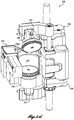
- FIGURE 4 is a perspective view of an exemplary brew group 130 in accordance with the present invention.
- the brew group 130 includes a cylindrical brewing chamber 132, currently formed with a cylindrical sleeve disposed in a block assembly 131.
- the brewing chamber 132 is positioned to receive coffee grounds from the grinder assembly 120 ( FIGURE 3 ).
- the brewing chamber defines a cylindrical volume between 2 inches and 3.5 inches in diameter, and a height between 2.5 inches and 5.0 inches.
- a sliding arm assembly 134 is slidably disposed over the brewing chamber 132, and is configured to push spent grounds or other brewed material off of the block assembly 131.
- the sliding arm assembly 134 includes a C-shaped arm 134A that extends across the width of the brewing chamber 132. The lower transverse edges of the C-shaped arm 134A are beveled.
- the arm 134A is drivably attached to a drive arm subassembly 134B.
- the drive arm subassembly 134B is movable linearly by an actuator 134C such that the C-shaped arm 134A is controllably movable across the upper surface of the block assembly 131.
- the actuator 134C comprises an electric motor-driven worm gear system with a toothed belt (not shown) that drivably engages the drive arm subassembly 134B.
- the actuator 134C, and the piston actuators discussed below are preferably configured with encoders (not shown) to enable precise positioning of the various elements.
- encoders not shown
- rotational sensors/encoders are provided on the drive motors
- linear sensors/encoders are provided on the drive shafts, to enable precise positional control.
- Exemplary sensors are Hall-effect sensors with magnets.
- a novel aspect of the illustrated sliding arm assembly 134 is the flexibility of the assembly, which provides a very reliable and effective mechanism for removing spent coffee grounds, as discussed below.
- the drive arm subassembly 134B slides along an upper surface of the actuator 134C, and includes a spring-loaded hinged connection 134D.
- a portion of the drive arm subassembly 134B extends behind the C-shaped arm 134A (see FIGURE 7E ) and is connected thereto with a pivot 134E.
- the flexibility of the sliding arm assembly 134 provides a very reliable mechanism for scraping spent grounds from the block assembly 131.
- the brew group 130 further includes an upper piston assembly 140 that is pivotably attached to an upper support arm 142.
- the upper piston assembly 140 is movable between a load position (shown in FIGURE 4 ) and a brewing position ( FIGURE 7B ) as discussed below, and is sized and configured to sealingly engage the brewing chamber 132 from an open top end of the chamber 132.
- the upper piston assembly 140 includes a dispensing tube 141 that dispenses the brewed beverage. The upper piston assembly 140 is described in more detail below.
- the upper support arm 142 is attached to a linear actuator.
- the linear actuator is a first lead screw assembly 146 comprising a lead screw 146A that is selectively and programmably driven with an electric motor 146B.
- a drive belt assembly 146C couples the motor 146B with the lead screw 146A.
- a protective cover 146D is disposed below the lead screw 146A and configured to receive and partially enclose the distal end of the lead screw 146A during operation.
- the upper piston assembly 140 is configured to pivot from the brewing position when it engages the brewing chamber 132, to the load position wherein the upper piston assembly 140 is pivoted away from the brewing chamber 132, to provide better access for loading brewable material into the brewing chamber 132 and to avoid interference with the sliding arm assembly 134. It will be appreciated by persons of skill in the art the pivotable upper piston assembly 140 reduces the height or head room required by the brew group 130.
- the brew group 130 further includes a lower piston assembly 150 that is pivotably attached to a lower support arm 152.
- the lower piston assembly 150 is sized and configured to sealingly engage the brewing chamber 132 from an open bottom end of the chamber 132, and includes a water supply tube 151.
- the lower piston assembly 150 is described in more detail below.
- the lower support arm 152 is attached to a linear actuator, which in this embodiment comprises a second lead screw assembly 156, similar to, and inverted relative to, the first lead screw assembly 146 described above.
- the second lead screw assembly 156 includes a lead screw 156A, and an electric motor 156B that drivably and programmably engages the lead screw 156A through a drive belt assembly 156C.
- a protective cover 156D is also provided to receive the distal portion of the lead screw 156A during operation.
- the lower piston assembly 150 does not disengage from the brewing chamber 132 during the brewing cycle, it the preferred embodiment the lower piston assembly 150 is pivotably attached to the lower support arm 152, which is configured to enable the lower piston assembly 150 to be moved away from the brewing chamber 132. This provides advantages in cleaning and servicing the system 100.
- the lead screw assemblies 146, 156 further include a guide slot 135 and anti-rotation pin 136 (only one anti-rotation device 135, 136 visible in FIGURE 4 ) to assure the corresponding piston moves only longitudinally.
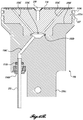
- FIGURE 5A shows a top view of the upper piston assembly 140
- FIGURE 5B shows a cross section of the upper piston assembly 140 through section 5B-5B
- FIGURE 5C shows an exploded view of the upper piston assembly 140.
- the upper piston assembly 140 defines a piston having a first piston member 140A that is configured to pivotably attach to the upper support arm 142, and includes a fixed lever arm 140B to facilitate pivoting the piston assembly 140.
- a channel 140C is defined from a front face of the first piston member 140A and extending to a lower face 140F.
- the channel 140C includes two straight segments and a larger distal end opening at the lower face.
- the dispensing tube 141 is attached to the first piston member 140A with a half cartridge fitting 140D and O-ring 140E, to fluidly and sealingly engage the channel 140C.
- a shaped recess 140F defines the lower face of the first piston member 140A.
- a second piston member 143A is configured to nest with and engage the shaped recess 140F as seen most clearly in FIGURE 5B .
- the second piston member 143A is removably attached to the first piston member 140A with a plurality of fasteners 143B ( FIGURE 5C ).
- a plurality of channels 143C extend through the second piston member 143A and fluidly engage the channel 140C in the first piston member 140A.
- An O-ring 143D is provided to seal the connection between the channel 140C and the plurality of channels 143C.
- the channels 140C, 143C therefore cooperatively define a plurality of fluid paths that extend from the lower face of the second piston member 143A to the dispensing tube 141.
- the first and second piston members 140A, 143A define an outer annular channel therebetween that is sized and configured to receive and retain a seal ring 147 that is configured to engage the cylindrical brewing chamber 132.
- a particular advantage of the two-member construction of the upper piston assembly 140 is that the ring seal 147 does not have to stretch over the outer piston diameter to engage the annular channel. It will be appreciated by persons of skill in the art that this allows the user of a stiffer material for the ring seal 147 and avoids risk of plastically deforming the ring seal 147, which must provide a seal for the hot brewed beverage and repeatedly engage and disengage the brewing chamber 132.
- a perforated plate 148 is removably attached to the bottom face of the second piston member 143A with a fastener 149.
- the bottom face of the second piston member 143A is configured with a plurality of intermittent ridges 143E that hold the perforated plate 148 away from the lower face of the second piston member 143A, to facilitate liquid flow to the channels 143C.
- the perforated plate 148 may also be provided with a replaceable micro-screen filter 148A or the like.
- FIGURE 5D shows a fragmentary side view of the upper piston assembly 140 in the pivoted or load position.
- the upper piston assembly 140 In the load position the upper piston assembly 140 is pivoted away from the brewing chamber 132.
- the fixed lever arm 140B engages an angled spring member 145 as the upper piston assembly 140 is moved upwardly.
- the angled spring member 145 is positioned such that the fixed lever arm 140B causes the piston to pivot about the pivot pin 142A as it engages and travels by the angled spring member 145.
- the bracket for the angled spring member 145 engages the fixed lever arm 140B causing the upper piston assembly 140 to pivot back toward the upright brew position, as discussed in more detail below.
- FIGURE 6A shows a bottom view of the lower piston assembly 150
- FIGURE 6B shows a section view of the lower piston assembly 150 through 6B-6B
- FIGURE 6C shows an exploded view of the lower piston assembly 150.
- the lower piston assembly 150 includes a first piston member 150A configured to attach to the lower support arm 152 ( FIGURE 4 ).
- a channel 150C extends from a lower opening in the first piston member 150A to an upper face 150F.
- the water supply tube 151 is attached to the first piston member 150A with a half cartridge fitting 150D and O-ring 150E to fluidly and sealingly engage the channel 150C.
- a shaped recess 150F defines the lower face of the first piston member 150A.
- a second piston member 153A is configured to nest with and engage the shaped recess 150F, and is removably attached thereto with a plurality of fasteners 153B.
- a plurality of channels 153C extend through the second piston member 153A and fluidly engage the channel 150C in the first piston member 150A.
- An O-ring 153D is provided to seal the connection.
- the channels 150C, 153C therefore cooperatively define a plurality of flow paths that extend from the water supply tube 151 to the upper face of the second piston member 153A.
- the first and second piston members 150A, 153A are configured to receive and retain a seal ring 157 therebetween that engages the brewing chamber 132.
- the second piston member 153A may further include a wiper ring 153E.
- a lower piston screen 158 is removably attached to the second piston member 153A with a fastener 159.
- FIGURES 7A-7E illustrate the brew group 130 in isolation with a portion of the brew chamber 132 cut away, at various stations in the brew cycle.
- FIGURE 3 illustrates components not shown in FIGURES 7A-7E for clarity. It is contemplated that the operation of the components of the brewing system 100 will be automatically controlled by the controller 110 and related systems, in response to the specific beverage request entered by a user from the beverage selection panel 106.
- Alternate means for entering a beverage request are also contemplated, for example using remote beverage entering system that is in signal communication with the brewing system 100, wirelessly (e.g., using RF, Bluetooth®, or the like) or using a card reading system, or the like.
- remote beverage entering system that is in signal communication with the brewing system 100, wirelessly (e.g., using RF, Bluetooth®, or the like) or using a card reading system, or the like.
- FIGURE 7A shows the brew group 130 in position to receive brewable material, for example ground coffee from the grinder assembly 130.
- the lower piston assembly 150 sealingly engages the brewing chamber 132, positioned near the lower end of the chamber 132 by the second lead screw assembly 156.
- the upper piston assembly 140 is positioned upwardly away from the brewing chamber 132 by the first lead screw assembly 146, and pivoted to the load position, as discussed above. Brewable material from the grinder assembly 120 is received into the brewing chamber 132.
- the upper piston assembly 140 is moved to the brewing position to sealingly engage an upper end of the brewing chamber 132.
- the upper piston assembly 140 pivots to a vertical orientation or brew position.
- the vertical position of the lower piston assembly 150 may also be adjusted, for example to accommodate the selected beverage size. For example, if a "small" or "8 ounce" beverage was selected, the lower piston assembly 150 may be moved upwardly in the brewing chamber 132. Valves (not shown) are positioned to close liquid egress from the brewing chamber 132, and to fluidly connect the heated water reservoir 114 to the water supply tube 151, to initiate the flow of hot water through the lower piston assembly 150 and into the brewing chamber 132.
- the water pressure is maintained at a desired value to optimize brewing quality and/or speed.
- a nominal pressure in the range between 10 and 100 psig is maintained, and more preferably in the range of 20-60 psig for coffee or in the range of 10-50 psig for other brewable product such as tea.
- the water supply may optionally be stopped to provide a desired time for brewing.
- the pressurized brewing chamber 132 although lower in pressure than espresso makers, will nevertheless accelerate the brewing process as compared to prior art systems wherein the brewing chamber is not pressurized.
- the pressurized water supply from the heater/reservoir is regulated to provide a desired pressure. It is contemplated that the regulated pressure may be between 10 and 100 psig.
- the water flow is resumed (or maintained) and a dispensing valve (not shown) is opened to initiate the flow of brewed beverage through the upper piston assembly channels 140C, 143C to the dispensing tube 141, and then ultimately dispensed to the cup, carafe or other container 90.
- a dispensing valve (not shown) is opened to initiate the flow of brewed beverage through the upper piston assembly channels 140C, 143C to the dispensing tube 141, and then ultimately dispensed to the cup, carafe or other container 90.
- the lower piston assembly 150 is moved upwardly through the brewing chamber 132, to cause the brewed liquid flow through the upper piston assembly 140 and to the dispensing tube 141.
- the first mode of operation will produce a different quality of beverage than the second mode because the grounds are not compressed until after the user beverage has been dispensed. Therefore, coffee (or tea) components released in the compression process will not be dispensed to the user. However, the system must then dispose of the remaining liquid in the brewing chamber 132.
- FIGURE 7C shows the brew group 130 wherein the lower piston assembly 150 has been moved upwardly part way through brewing chamber 132.
- one or more valves redirect the flow to a drain that is preferably plumbed into the system 100.
- the upward movement of the lower piston assembly 150 dispenses the brewed liquid. In either case, the now spent brewed material is compressed between the upper piston assembly 140 and the lower piston assembly 150, such that a significant portion of the water is removed.
- the upper piston assembly 140 is moved upwardly to disengage from the brewing chamber 132 and pivots to the load position.
- the lower piston assembly 150 is moved upwardly such that the piston is approximately flush with the upper surface of the block assembly 131.
- the compressed spent grounds are therefore positioned to be removed, and the upper piston assembly 140 is moved out of the way of the sliding arm assembly 134.
- FIGURE 7E shows the sliding arm assembly 134 after sliding the C-shaped arm 134A over the brewing chamber 132 to remove the spent grounds.
- the system 100 may include an internal repository or chute for the spent grounds, or may be positioned over an external repository positioned to receive the grounds.
- the sliding arm assembly 134 may then be retracted, to return to the ready position shown in FIGURE 7A .
- the flexible sliding arm assembly 134 is able to overcome certain obstacles while still effectively removing the spent grounds. For example, if the lower piston assembly 150 extends to a position slightly higher than the upper surface of the block assembly 131, the spring-loaded hinge connection 134D permits the drive arm subassembly 134B to adjust as the lower beveled edge of the C-shaped arm 134A encounters the piston. Moreover, because the drive arm subassembly 134B pivotably engages the C-shaped arm 134A at or near the center of the arm, the arm 134A will maintain a relatively uniform engagement and downward force on the lower piston assembly 150, to effectively remove the spent grounds.
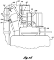
- FIGURES 8A-8E illustrate the motion of the chute assembly and the upper piston assembly 140 as the upper piston assembly 140 moves from the load position to the brewing position.
- FIGURE 8A shows the upper piston assembly 140 in the load position with the upper support arm 142 at or near its uppermost position.
- a chute assembly 160 is pivotably attached to the chute base 126.
- an upper chute member 162 is pivotably attached and biased outwardly (counterclockwise in FIGURES 8A-8E ) with an upper pivot assembly 161.
- the upper chute member 162 has a generally inverted U-shaped cross-section with downwardly-extending sidewalls.
- a lower chute member 164 is pivotably attached and biased outwardly (counterclockwise in FIGURES 8A-8E ) below the upper chute member 162 with a lower pivot assembly 163.
- the lower chute member has a generally U-shaped cross-section with upwardly-extending sidewalls that overlap the upper chute member 162. It will be appreciated that in the load position, the chute assembly 160 is configured to direct brewable material such as coffee grounds directly and cleanly into the brewing chamber 132, while preventing the grounds from being inadvertently spread to other locations in the system.
- brewable material such as coffee grounds directly and cleanly into the brewing chamber 132
- FIGURE 8B shows the upper piston assembly 140 with the upper support arm 142 moved downwardly a short distance, as the fixed lever arm 140B of the upper piston assembly 140 engages the spring member 145 and begins to pivot toward an upright orientation.
- FIGURE 8C shows the upper piston assembly 140 with the upper support arm 142 moved further toward the brewing position.
- the upper piston assembly 140 has pivoted further towards an upright orientation due to the engagement of the fixed lever arm 140B with the spring member 145.
- a strike plate 144 fixed to a face of the upper piston assembly 140 in this position now engages the lower chute member 164, and begins to pivot the lower chute member 164 out of the way, against the bias of the pivot assembly 163.
- FIGURE 8D shows the upper piston assembly 140 with the upper support arm 142 moved downwardly an additional distance.
- the upper piston assembly 140 has now pivoted to an upright position, and the fixed lever arm 140B engages a stop 165 on the upper support arm 142, which prevents the upper piston assembly 140 from pivoting further.
- FIGURE 8E shows the upper piston assembly 140 with the upper support arm 142 moved downwardly to the brewing position wherein the upper piston assembly 140 sealingly engages the brewing chamber 132, as discussed above.
- the spring member 145 is forced out of the way by the fixed lever arm 140B, against the bias of the spring member 145. It will be appreciated that the reverse kinematics will pivot the upper piston assembly 140 to the load position when the upper support arm 142 is moved upwardly.
- FIGURE 9 shows a hydraulic diagram for an embodiment of the brewing system 100, showing additional optional aspects of the system.
- the present invention will typically be implemented in an automated system that preferably provides for user selectable parameters. Therefore, the sensor information and various control elements such as the heater, valves, display elements, and the like will typically provide data to an onboard computer or control system and/or receive control signals from the control system.
- the computerized control system would typically include a processing unit, signal generating and receiving components, memory elements, and the like, as are well known in the art.
- the water enters through a water filtration system 200, and may include a check valve 202 to prevent backflow, and a manual valve 204.
- a pressure regulator 206 and flow meter 208 are provided upstream of the water reservoir/heater 114, which includes an internal heating element 114A.
- the water reservoir/heater 114 is configured with suitable sensors and controls, for example a temperature probe 210, water level probe 212, and high limit switch 214.
- a hot water valve 216 may be provided to permit dispensing of hot water directly, without going through the brewer group 130.
- a brew valve 218 is operable to direct hot water to the brew group 130, and may further engage a water gauge 220, and pressure relief valve 224 with an expansion valve 226 to a drain.
- An optional flavor system 130 includes a selection of flavorings 232 that may be controllably pumped 234 to a syrup block 236 to be mixed with the brewed coffee liquid prior to dispensing to the carafe 90 or other container.
- a bypass valve 236 may be engaged if no flavoring was selected.
- a significant quantity of brewed liquid is not dispensed, but rather is expelled from the brewing chamber 132 by the lower piston assembly 150 after dispensing the user beverage. This liquid may be directed to a drain through the drain valve 222.
- the currently preferred system provides for a liquid flow through the brewing chamber 132 that is initiated with heated water entering through the lower piston assembly 150 at the bottom of the brewing chamber 132, and brewed liquid exiting through the upper piston assembly 140.
- the present invention may be practiced with the liquid flow proceeding in the opposite direction.
Claims (17)
- Groupe de brassage (130) comprenant :(a) une chambre de brassage (132) ayant une surface supérieure et une ouverture cylindrique avec une première extrémité ouverte et une seconde extrémité ouverte ;(b) un ensemble de piston inférieur (150) dimensionné et configuré pour engager de manière coulissante la première extrémité ouverte de la chambre de brassage (132) ;(c) un premier actionneur relié à l'ensemble de piston inférieur (150) et capable de déplacer l'ensemble de piston inférieur (150) longitudinalement dans l'ouverture cylindrique ;(d) un ensemble de piston supérieur (140) dimensionné et configuré pour engager de manière coulissante la seconde extrémité ouverte de la chambre de brassage (132) ;(e) un second actionneur relié à l'ensemble de piston supérieur (140) et capable de déplacer l'ensemble de piston supérieur (140) entre (i) une position de chargement dans laquelle l'ensemble de piston supérieur est disposé au-dessus de la chambre de brassage (132) et est pivoté à l'écart de la chambre de brassage (132), et (ii) une position de brassage dans laquelle l'ensemble de piston supérieur (140) engage de manière coulissante la chambre de brassage (132) ;(f) un moyen de pivotement de l'ensemble de piston supérieur (140) à l'écart de la chambre de brassage (132) lorsque le second ensemble de piston (140) est déplacé dans la position de chargement ;(g) un ensemble de bras coulissant (134) ayant un bras de raclage disposé de manière coulissante sur la surface supérieure de la chambre de brassage ; et(h) un troisième actionneur capable de déplacer le bras de raclage sur la surface supérieure de la chambre de brassage (132), par-dessus la seconde extrémité ouverte de la chambre de brassage (132), le bras de raclage étant relié par articulation au troisième actionneur ;caractérisé en ce que l'ensemble de piston inférieur (150) définit un canal d'écoulement (150C) à l'intérieur, qui relie fluidiquement la chambre de brassage (132) à un tube d'alimentation en eau externe (151).
- Groupe de brassage (130) selon la revendication 1, dans lequel l'ensemble de piston inférieur (150) comprend un premier élément de piston et un second élément de piston qui est relié de manière amovible au premier élément de piston.
- Groupe de brassage (130) selon la revendication 2, dans lequel le premier élément de piston et le second élément de piston définissent de manière coopérative une rainure périphérique annulaire, et comprenant en outre une bague d'étanchéité disposée dans la rainure périphérique annulaire, dans lequel la bague d'étanchéité est configurée pour engager de manière étanche la chambre de brassage.
- Groupe de brassage (130) selon la revendication 1, dans lequel l'ensemble de piston supérieur (140) comprend un premier élément de piston (140A) qui est relié au second actionneur, un second élément de piston qui est relié de manière amovible au premier élément de piston (140A), le premier et le second éléments de piston définissant de manière coopérative un canal annulaire, et une bague d'étanchéité (147) disposée dans le canal annulaire.
- Groupe de brassage (130) selon la revendication 4, dans lequel le premier élément de piston (140A) définit un canal d'écoulement à l'intérieur, et le second élément de piston comprend une pluralité de canaux d'écoulement à l'intérieur, qui engagent fluidiquement le canal d'écoulement du premier élément de piston.
- Groupe de brassage (130) selon la revendication 5, dans lequel l'ensemble de piston supérieur (140) comprend en outre un tube de distribution (141) qui engage de manière étanche le canal d'écoulement du premier élément de piston.
- Groupe de brassage (130) selon la revendication 6, dans lequel l'ensemble de piston supérieur (140) comprend en outre un joint disposé entre le canal d'écoulement du premier élément de piston et la pluralité de canaux d'écoulement du second élément de piston.
- Groupe de brassage (130) selon la revendication 6, comprenant en outre une plaque perforée (148) reliée à une face distale du second élément de piston.
- Groupe de brassage (130) selon la revendication 8, dans lequel une face distale du second élément de piston est configurée avec une pluralité d'éléments d'espacement (143E) de sorte qu'un trajet d'écoulement soit défini entre la face distale du second élément de piston et la plaque perforée (148).
- Groupe de brassage (130) selon la revendication 1, dans lequel le premier actionneur comprend une vis-mère.
- Groupe de brassage (130) selon la revendication 1, dans lequel le moyen de pivotement de l'ensemble de piston supérieur (140) comprend un bras de levier sur l'ensemble de piston supérieur et un ressort fixe qui engage le bras de levier afin de faire pivoter l'ensemble de piston supérieur lorsque l'ensemble de piston supérieur est déplacé dans la position de chargement.
- Groupe de brassage (130) selon la revendication 1, dans lequel le groupe de brassage (130) est configuré pour maintenir une pression de liquide entre 10 psig et 100 psig lorsque le groupe de brassage brasse un liquide brassé.
- Procédé de fabrication d'une boisson brassable comprenant les étapes consistant à :(a) prévoir un groupe de brassage (130) ayant (i) une chambre de brassage (132) définissant une ouverture cylindrique ayant une première extrémité ouverte et une seconde extrémité ouverte ; (ii) un ensemble de piston inférieur (150) qui engage de manière coulissante la première extrémité ouverte de l'ouverture cylindrique ;(iii) un ensemble de piston supérieur (140) mobile entre une position de chargement dans laquelle l'ensemble de piston supérieur est disposé au-dessus de l'ouverture cylindrique et est pivoté à l'écart de l'ouverture cylindrique, et une position de brassage dans laquelle l'ensemble de piston supérieur (140) engage de manière étanche la seconde extrémité ouverte de l'ouverture cylindrique ; et (iv) un ensemble de bras coulissant (134) configuré avec un actionneur (134C), l'ensemble de bras coulissant (134) étant configuré pour coulisser par-dessus la seconde extrémité ouverte de l'ouverture cylindrique, l'ensemble de bras coulissant (134) étant relié par articulation à l'actionneur (134C) ;(b) avec l'ensemble de piston supérieur (140) en position de chargement, déposer une matière brassable dans la chambre de brassage (132) ;(c) déplacer l'ensemble de piston supérieur (140) en position de brassage ;(d) déclencher un flux d'eau chauffée dans la chambre de brassage (132) afin de produire une pression de brassage comprise entre 10 psig et 100 psig ;(e) arrêter l'écoulement d'eau chauffée dans la chambre de brassage (132) et permettre à la matière brassable d'être brassée afin de produire un liquide brassé dans la chambre de brassage (132) ;(f) former une partie du liquide brassé en-dehors de la chambre de brassage (132) ;(g) déplacer le piston inférieur (150) partiellement dans l'ouverture cylindrique de sorte que la matière brassable soit compressée entre l'ensemble de piston supérieur (140) et l'ensemble de piston inférieur (150) ;(h) déplacer l'ensemble de piston supérieur (140) en position de chargement ;(i) déplacer le piston inférieur (150) dans l'ouverture cylindrique jusqu'à une position qui affleure sensiblement la seconde extrémité ouverte de l'ouverture cylindrique ; et(j) déplacer l'ensemble de bras coulissant (134) par-dessus la seconde extrémité ouverte de l'ouverture cylindrique afin de retirer la matière brassable,caractérisé en ce que l'étape qui consiste à forcer le liquide brassé en-dehors de la chambre de brassage (132) est exécutée en déplaçant de manière coulissante l'ensemble de piston inférieur (150) dans la chambre de brassage.
- Procédé selon la revendication 13, dans lequel l'étape qui consiste à forcer la boisson brassée en-dehors de la chambre de brassage est exécutée en relançant le flux d'eau chauffée dans la chambre de brassage.
- Procédé selon la revendication 13, dans lequel l'ensemble de piston supérieur (140) comprend en outre un canal à l'intérieur qui est relié fluidiquement à un tube de distribution, et dans lequel le liquide brassé est forcé en-dehors de la chambre de brassage par le tube de distribution.
- Procédé selon la revendication 13, dans lequel la pression de brassage produite est comprise entre 20 psig et 60 psig.
- Groupe de brassage (130) selon la revendication 1, comprenant en outre :(a) une trémie configurée pour distribuer des grains de café ;(b) un broyeur configuré pour recevoir les grains de café qui proviennent de la trémie et pour distribuer du café moulu ;(c) un réservoir d'eau chauffée ;(d) un contrôleur programmable relié afin de contrôler le fonctionnement de la trémie, du broyeur, du réservoir, du premier actionneur, du second actionneur, et du moyen coulissant afin de déposer sélectivement du café moulu dans la chambre de brassage (132), de fermer la chambre de brassage (132), de fournir l'eau chauffée entre 10 psig et 100 psig à la chambre de brassage (132), et de distribuer un liquide brassé depuis la chambre de brassage (132).
Applications Claiming Priority (2)
| Application Number | Priority Date | Filing Date | Title |
|---|---|---|---|
| US30940110P | 2010-03-01 | 2010-03-01 | |
| PCT/US2011/026754 WO2011109443A2 (fr) | 2010-03-01 | 2011-03-01 | Dispositif de brassage à basse pression à circulation accélérée |
Publications (3)
| Publication Number | Publication Date |
|---|---|
| EP2542127A2 EP2542127A2 (fr) | 2013-01-09 |
| EP2542127A4 EP2542127A4 (fr) | 2015-04-01 |
| EP2542127B1 true EP2542127B1 (fr) | 2018-05-30 |
Family
ID=44505426
Family Applications (1)
| Application Number | Title | Priority Date | Filing Date |
|---|---|---|---|
| EP11751236.8A Active EP2542127B1 (fr) | 2010-03-01 | 2011-03-01 | Dispositif de brassage à basse pression à circulation accélérée |
Country Status (14)
| Country | Link |
|---|---|
| US (1) | US8247010B2 (fr) |
| EP (1) | EP2542127B1 (fr) |
| JP (1) | JP2013521059A (fr) |
| KR (1) | KR20130004910A (fr) |
| CN (1) | CN102843937B (fr) |
| AU (1) | AU2011223792B2 (fr) |
| BR (1) | BR112012021800A2 (fr) |
| CA (1) | CA2790679C (fr) |
| HK (1) | HK1174519A1 (fr) |
| MX (1) | MX338510B (fr) |
| NZ (1) | NZ602100A (fr) |
| RU (1) | RU2012141643A (fr) |
| SG (1) | SG183525A1 (fr) |
| WO (1) | WO2011109443A2 (fr) |
Families Citing this family (27)
| Publication number | Priority date | Publication date | Assignee | Title |
|---|---|---|---|---|
| US8528466B2 (en) * | 2010-02-05 | 2013-09-10 | Bobbi J Sweet | Liquid overflow platform and container for small appliances |
| US8616116B2 (en) * | 2010-03-01 | 2013-12-31 | Concordia Coffee Company, Inc. | High speed brewing apparatus |
| ITRM20110458A1 (it) * | 2011-09-05 | 2013-03-06 | Iacobucci Hf Electronics S P A | Dispositivo porta-cialda per macchina erogatrice di bevande |
| SG11201402565UA (en) | 2011-11-23 | 2014-06-27 | Starbucks Corp Dba Starbucks Coffee Co | Apparatus, systems, and methods for brewing a beverage |
| ITPN20120050A1 (it) | 2012-09-07 | 2014-03-08 | Cma Macchine Per Caffe S R L | MACCHINA DA CAFFEÂeuro¿ AUTOMATICA PER LA PREPARAZIONE DI CAFFEÂeuro¿ ESPRESSO |
| US20140102308A1 (en) * | 2012-10-12 | 2014-04-17 | Christian KOESTER | Brewing unit for a coffee machine |
| NL2009833C2 (nl) | 2012-11-16 | 2014-05-19 | People Creating Value Holding B V | Inrichting voor het bereiden van een drank alsmede een zetinrichting. |
| FR3000657B1 (fr) * | 2013-01-07 | 2017-12-29 | Seb Sa | Distributeur automatique de boisson infusee a partir d'une mouture |
| USD738667S1 (en) | 2013-11-20 | 2015-09-15 | Starbucks Corporation | Beverage brewing apparatus |
| WO2015077237A2 (fr) * | 2013-11-20 | 2015-05-28 | Starbucks Corporation D/B/A Starbucks Coffee Company | Gestion de l'alimentation en courant de systèmes de cuisson |
| EP3110298A4 (fr) * | 2014-02-27 | 2017-11-08 | Bkon LLC | Système et procédé d'infusion de boissons |
| EP3166456B1 (fr) * | 2014-07-09 | 2018-09-26 | Nestec S.A. | Accessoire pour alimenter automatiquement une machine de boisson avec un liquide provenant d'un réseau de distribution |
| EP3166458B1 (fr) * | 2014-07-09 | 2021-05-05 | Société des Produits Nestlé S.A. | Couplage d'un dispositif de raccordement d'une machine à boisson à un réseau de distribution |
| ES2757601T3 (es) * | 2014-07-09 | 2020-04-29 | Nestle Sa | Dispositivo para conectar una máquina de bebidas a una red de distribución con monitorización de seguridad |
| ES2828253T3 (es) * | 2014-07-09 | 2021-05-25 | Nestle Sa | Dispositivo para conectar una máquina de bebidas a una red de distribución con interrupción segura de flujo |
| US20160022087A1 (en) | 2014-07-24 | 2016-01-28 | Teforia Company | Apparatus And Method Of Multi-Course Infusion For Brewing Tea And Other Beverages |
| US10722065B2 (en) | 2014-07-24 | 2020-07-28 | Adagio Teas, Inc. | Apparatus and method of multi-course infusion for brewing tea and other beverages |
| WO2016124573A1 (fr) * | 2015-02-05 | 2016-08-11 | De' Longhi Appliances S.R.L. | Cafetière et son procédé de commande |
| EP3310221B1 (fr) | 2015-06-19 | 2018-10-24 | Koninklijke Philips N.V. | Procede permettant de recuperer un arome a partir d'une certaine quantite de particules de cafe presentes dans une chambre de cafe |
| DE102016000406B4 (de) * | 2016-01-14 | 2023-06-01 | Smiics Gmbh | Vorrichtung zur Zubereitung von Babynahrung |
| US20170119200A1 (en) * | 2016-01-19 | 2017-05-04 | Anthony David Bressi | Automated beverage and fragrance synthesizers |
| PT109304B (pt) * | 2016-04-07 | 2021-02-26 | Novadelta - Comércio E Indústria De Cafés, S.A. | Dispositivo de extração com câmara de recolha adaptada |
| US20170318999A1 (en) * | 2016-05-05 | 2017-11-09 | Teforia Company | Apparatus for Brewing a Beverage |
| EP3478135B1 (fr) | 2016-06-30 | 2020-04-08 | Société des Produits Nestlé S.A. | Machine de préparation de boisson avec une pompe régulée |
| IT201700071902A1 (it) * | 2017-06-27 | 2018-12-27 | Carimali S P A Con Socio Unico | Dispositivo infusore |
| US20210401221A1 (en) * | 2018-06-27 | 2021-12-30 | Carimali S.P.A. | A brewing device for a beverage preparation machine, in particular coffee or tea |
| CN113727632B (zh) | 2018-12-24 | 2023-05-26 | 卡里马里股份公司 | 用于制备饮料的冲泡装置 |
Family Cites Families (96)
| Publication number | Priority date | Publication date | Assignee | Title |
|---|---|---|---|---|
| US2733731A (en) * | 1956-02-07 | Turak | ||
| US332199A (en) * | 1885-12-08 | Drier | ||
| US2658645A (en) * | 1950-01-31 | 1953-11-10 | Edwin M Thomas | Dispensing machine for beverages having plural ingredients |
| GB1024161A (en) * | 1963-09-25 | 1966-03-30 | Fisher & Ludlow Ltd | Improvements in or relating to coin freed vending machines |
| US3369478A (en) * | 1966-04-22 | 1968-02-20 | Vendo Co | Single cup, dry waste coffee brewing and dispensing mechanism |
| US3385569A (en) * | 1967-01-11 | 1968-05-28 | Rock Ola Mfg Corp | Mixing apparatus for beverage |
| US3671273A (en) * | 1968-05-20 | 1972-06-20 | Alec C Gunter | Apparatus for preparing a cocoa concentrate |
| US4211342A (en) * | 1978-02-22 | 1980-07-08 | Ara Services, Inc. | Combination hot and cold drink machine |
| ES235333Y (es) * | 1978-04-12 | 1978-11-01 | Nuevo aparato automatico para la preparacion de cafe ex- pres. | |
| ES479290A1 (es) * | 1979-04-04 | 1980-05-16 | Valente Paolo | Perfeccionamientos introducidos en los aparatos para prepa- racion de cafe expres. |
| JPS59184998A (ja) * | 1983-04-05 | 1984-10-20 | サンデン株式会社 | 複数品種のコ−ヒ−をブレンドして販売可能とした自動販売機 |
| USD289129S (en) * | 1984-06-18 | 1987-04-07 | Fountain Industries, Inc. | Hot beverage server |
| JPS6146686U (ja) * | 1984-08-31 | 1986-03-28 | サンデン株式会社 | 飲料販売機 |
| US4713138A (en) | 1984-12-26 | 1987-12-15 | Nevamar Corporation | Method of producing abrasion-resistant decorative laminate |
| ES8700918A1 (es) * | 1985-01-31 | 1986-11-16 | Spidem Srl | Perfeccionamientos en los dispositivos emulsionadores |
| DE3607656A1 (de) * | 1986-03-08 | 1987-09-17 | Cafina Ag | Kolben-zylinder-aggregat fuer eine kaffeemaschine und verfahren zum betrieb |
| JPS63181718A (ja) * | 1987-01-21 | 1988-07-26 | 松下電器産業株式会社 | 抽出装置 |
| DK169805B1 (da) * | 1987-02-24 | 1995-03-06 | Nelle J Van Bv | Apparat til tillavning af kaffe |
| US5033645A (en) * | 1987-10-13 | 1991-07-23 | Abc/Sebrn Tech Corp. | Carbonation system for soft drink dispenser |
| USD318973S (en) * | 1987-12-01 | 1991-08-13 | Robert Kurps Stiftung & Co. KG. | Combined coffee and espresso making machine |
| USD313724S (en) * | 1988-02-11 | 1991-01-15 | Gaggia Espanola, S.A. | Coffee maker |
| USD316794S (en) * | 1988-11-16 | 1991-05-14 | Cafina Ag | Coffee machine |
| US5116632A (en) * | 1988-12-22 | 1992-05-26 | Miller Harold F | Brewing and dispensing system and method for iced tea |
| US5207148A (en) * | 1990-06-25 | 1993-05-04 | Caffe Acorto, Inc. | Automated milk inclusive coffee apparatus |
| USD337475S (en) * | 1990-12-12 | 1993-07-20 | Robert Krups Gmbh & Co. Kg | Espresso making machine |
| IT221582Z2 (it) * | 1991-01-25 | 1994-07-22 | Ricerca Elettromeccanica Srl | Apparecchio per la produzione di caffe' |
| US5134925A (en) | 1991-04-10 | 1992-08-04 | Bunn-O-Matic Corporation | Automatic brewer |
| US5393540A (en) * | 1991-04-10 | 1995-02-28 | Bunn-O-Matic Corporation | Automatic beverage brewing method |
| US5303639A (en) * | 1991-04-10 | 1994-04-19 | Bunn-O-Matic Corporation | Automatic brewer |
| IT1247502B (it) * | 1991-04-19 | 1994-12-17 | Spidem Srl | Dispositivo di emulsionamento particolarmente per bevande in genere |
| IT1250447B (it) * | 1991-07-03 | 1995-04-07 | Lucio Grossi | Macchina automatica per la produzione di caffe' con azionamento a motore in corrente continua e viti senza fine. |
| USD340611S (en) * | 1991-07-22 | 1993-10-26 | Hoover Billy H | Coffee dispenser |
| ES2084325T3 (es) * | 1991-07-30 | 1996-05-01 | Sintra Holding Ag | Dispositivo para expulsar del sistema de escaldar de una cafetera la torta de cafe molido agotado y prensado. |
| DK0528757T3 (da) * | 1991-07-30 | 1996-01-22 | Sintra Holding Ag | Bryggeindretning til en kaffemaskine og fremgangsmåde til fremstilling af kaffe |
| DE4133697A1 (de) * | 1991-10-11 | 1993-04-15 | Hgz Maschinenbau Ag | Kaffeemaschinenautomat |
| ATE171352T1 (de) * | 1992-07-20 | 1998-10-15 | Nestle Sa | Verfahren und vorrichtung zur extraktion undurchlässiger, verformbarer portionspackungen |
| US5344050A (en) * | 1993-04-01 | 1994-09-06 | Unidynamics Corporation | Moisture reduction system for an automatic vending machine |
| US5650186A (en) * | 1993-06-07 | 1997-07-22 | Annoni; Faust | Hot beverage brewing and dispensing apparatus and method |
| US5657683A (en) * | 1993-06-07 | 1997-08-19 | Sandei; Pietro | Hot beverage brewing apparatus |
| US5353692A (en) * | 1993-09-29 | 1994-10-11 | Unidynamics Corporation | Hot beverage brewing apparatus |
| US5423245A (en) * | 1994-04-13 | 1995-06-13 | Bunn-O-Matic Corporation | Milk foaming device |
| USD365490S (en) * | 1994-09-30 | 1995-12-26 | Caffe Acorto, Inc. | Automatic coffee machine |
| US5579678A (en) * | 1995-10-06 | 1996-12-03 | Royal Cup, Inc. | Apparatus for automatically sweetening tea |
| USD396987S (en) * | 1995-10-18 | 1998-08-18 | Robert Krups Gmbh & Co. Kg | Espresso maker |
| USD395975S (en) * | 1995-12-29 | 1998-07-14 | Gaggia Espanola, S.A. | Coffee machine |
| KR100224296B1 (ko) * | 1996-04-13 | 1999-10-15 | 배길성 | 원두커피 자동판매기의 가열장치 |
| NL1002936C2 (nl) * | 1996-04-24 | 1997-10-28 | Sara Lee De Nv | Samenstel voor het bereiden van warme en geschuimde melk. |
| USD414371S (en) * | 1997-03-24 | 1999-09-28 | Robert Krups Gmbh & Co Kg | Electric espresso making machine |
| US5911810A (en) * | 1997-06-23 | 1999-06-15 | Sanden Corp. | Coffee brewing apparatus and method of brewing coffee by the apparatus |
| CN1142740C (zh) * | 1997-09-05 | 2004-03-24 | 西布公司 | 用于饮料自动配给器的尤其包括一个加热器的调制装置 |
| US5823096A (en) * | 1997-10-14 | 1998-10-20 | Shih; Chun-Hong | Automatic infusing apparatus |
| IT1304276B1 (it) * | 1998-04-15 | 2001-03-13 | Ducale Macchine Da Caffe Di Sa | Distributore automatico di bevande in bicchiere. |
| USD413757S (en) * | 1998-08-03 | 1999-09-14 | Gaggia Espanola, S.A. | Coffee machine |
| US6098524A (en) * | 1998-09-16 | 2000-08-08 | Crane Co. | Hot beverage vending machine |
| USD417118S (en) * | 1998-10-30 | 1999-11-30 | Acorto, Inc. | Automatic espresso machine |
| US6019032A (en) * | 1998-10-30 | 2000-02-01 | Acorto, Inc. | Automated espresso and milk aeration apparatus and method |
| US6240829B1 (en) * | 1999-02-12 | 2001-06-05 | Pepsico. Inc. | Tea or non-carbonated drink dispenser |
| US6182555B1 (en) * | 1999-04-07 | 2001-02-06 | Red River Tea Company | Apparatus and methods for brewing and dispensing beverages |
| US6237811B1 (en) * | 1999-10-08 | 2001-05-29 | Bunn-O-Matic Corporation | Programmable dispenser |
| USD449198S1 (en) * | 2000-02-02 | 2001-10-16 | Societe Des Produits Nestle S.A. | Coffee machine |
| IT1320486B1 (it) * | 2000-05-31 | 2003-12-10 | Rancilio Macchine Per Caffe Sp | Macchina per caffe'. |
| CA2313794C (fr) * | 2000-07-12 | 2008-09-16 | Bertone Holdings Inc. | Distributeur de boissons chaudes a saveurs multiples |
| AU144613S (en) * | 2000-07-14 | 2001-07-31 | Rancilio Macch Per Caffe Spa | Coffee machine |
| USD455596S1 (en) * | 2000-10-13 | 2002-04-16 | Wmf Wuerttembergische Metallwarenfabrik Ag | Coffee machine |
| JP2002319068A (ja) * | 2001-04-19 | 2002-10-31 | Sanden Corp | 自動販売機の飲料抽出装置 |
| EP1436226A4 (fr) * | 2001-09-06 | 2008-07-16 | Manitowoc Foodservice Co Inc | Distributeur de boissons a faible volume |
| EP1312291A1 (fr) | 2001-11-20 | 2003-05-21 | M. Schaerer AG | Machine à café |
| USD481901S1 (en) * | 2002-01-28 | 2003-11-11 | BSH Bosch und Siemens Hausgeräte GmbH | Automatic coffee maker |
| US6786134B2 (en) * | 2002-02-07 | 2004-09-07 | The Coca-Cola Company | Coffee and tea dispenser |
| FR2840176B1 (fr) * | 2002-06-03 | 2004-08-06 | Cie Mediterraneenne Des Cafes | Dispositif de production de boisson par infusion |
| US6994231B2 (en) * | 2002-05-14 | 2006-02-07 | Jones Charles H | System and method for dispensing beverages |
| US7021206B2 (en) * | 2002-06-18 | 2006-04-04 | Eckenhausen Roland B | Hot dairy-based beverage dispenser |
| JP3620841B2 (ja) * | 2002-09-12 | 2005-02-16 | 忠至 湯沢 | コーヒー飲料の製造方法 |
| USD486346S1 (en) * | 2002-10-01 | 2004-02-10 | Jura Elektroapparate Ag | Coffee maker |
| KR100515471B1 (ko) | 2003-03-12 | 2005-09-20 | 삼성광주전자 주식회사 | 커피머신의 커피추출장치 |
| USD495915S1 (en) * | 2003-05-08 | 2004-09-14 | Societe Des Produits Nestle S.A. | Coffee machine |
| JP2005152188A (ja) * | 2003-11-25 | 2005-06-16 | Hoshizaki Electric Co Ltd | 飲料抽出機 |
| US7147131B2 (en) * | 2003-12-05 | 2006-12-12 | Nestec S.A. | Method and system for dispensing hot and cold beverages from liquid concentrates |
| DE102004006095A1 (de) * | 2004-02-06 | 2005-09-01 | Niro-Plan Ag | Vorrichtung zur Erzeugung von Milchschaum |
| DE102004023964B3 (de) * | 2004-05-14 | 2006-01-19 | HGZ Maschinenbau AG, Dällikon | Kaffeemaschinenautomat |
| US7226631B2 (en) * | 2004-08-12 | 2007-06-05 | Nestec S.A. | Method and apparatus for consumable powder reconstitution and frothing |
| JP2006244448A (ja) * | 2005-02-02 | 2006-09-14 | Kubota Corp | 飲料抽出装置 |
| WO2007035877A2 (fr) | 2005-04-11 | 2007-03-29 | Coffee Equipment Company | Machine destinee a l'infusion de boissons telles que le cafe et procede associe |
| WO2007027206A2 (fr) * | 2005-04-11 | 2007-03-08 | Coffee Equipment Company | Machine pour infuser une boisson comme du café et procédé s'y rapportant |
| USD536204S1 (en) * | 2005-04-13 | 2007-02-06 | Isett David E | Drink dispensing kiosk |
| US20060254428A1 (en) * | 2005-05-14 | 2006-11-16 | Glucksman Dov Z | Coffee making apparatus |
| US7507430B2 (en) * | 2005-06-10 | 2009-03-24 | Concordia Coffee Company, Inc. | Method for preparing a heated flavored beverage |
| US7537138B2 (en) * | 2005-06-20 | 2009-05-26 | Nestec S.A. | Methods and systems for delivering foamed beverages from liquid concentrates |
| DE602005012979D1 (de) * | 2005-12-23 | 2009-04-09 | Rancilio Macchine Caffe | Brühvorrichtung |
| PL2140788T3 (pl) | 2006-06-14 | 2012-11-30 | Rheavendors Services Spa | Ulepszona jednostka zaparzacza do automatycznych ekspresów do kawy |
| USD556493S1 (en) * | 2006-08-16 | 2007-12-04 | Concordia Coffee Company, Inc. | Drink dispensing kiosk |
| US9226611B2 (en) * | 2007-06-05 | 2016-01-05 | Nestec S.A. | Capsule system, device and method for preparing a food liquid contained in a receptacle by centrifugation |
| DE602008004073D1 (de) * | 2008-01-02 | 2011-02-03 | Emparanza Y Glados Internac S A | Kaffeemaschine mit Druckablassventil |
| JP2010029303A (ja) * | 2008-07-25 | 2010-02-12 | Apex:Kk | 飲料ブルワ、飲料抽出機及び飲料生成方法 |
| US8616116B2 (en) * | 2010-03-01 | 2013-12-31 | Concordia Coffee Company, Inc. | High speed brewing apparatus |
| US8623441B2 (en) * | 2010-03-01 | 2014-01-07 | Concordia Coffee Company, Inc. | Method and apparatus for controlling brewed beverage quality |
-
2011
- 2011-03-01 AU AU2011223792A patent/AU2011223792B2/en active Active
- 2011-03-01 KR KR1020127024366A patent/KR20130004910A/ko not_active Application Discontinuation
- 2011-03-01 JP JP2012556187A patent/JP2013521059A/ja active Pending
- 2011-03-01 WO PCT/US2011/026754 patent/WO2011109443A2/fr active Application Filing
- 2011-03-01 US US13/038,195 patent/US8247010B2/en active Active
- 2011-03-01 SG SG2012063772A patent/SG183525A1/en unknown
- 2011-03-01 BR BR112012021800A patent/BR112012021800A2/pt not_active IP Right Cessation
- 2011-03-01 CN CN201180011950.9A patent/CN102843937B/zh active Active
- 2011-03-01 RU RU2012141643/12A patent/RU2012141643A/ru unknown
- 2011-03-01 CA CA2790679A patent/CA2790679C/fr active Active
- 2011-03-01 NZ NZ602100A patent/NZ602100A/xx unknown
- 2011-03-01 EP EP11751236.8A patent/EP2542127B1/fr active Active
- 2011-03-01 MX MX2012010060A patent/MX338510B/es active IP Right Grant
-
2013
- 2013-02-15 HK HK13101920.8A patent/HK1174519A1/xx unknown
Non-Patent Citations (1)
| Title |
|---|
| None * |
Also Published As
| Publication number | Publication date |
|---|---|
| MX338510B (es) | 2016-04-20 |
| EP2542127A2 (fr) | 2013-01-09 |
| BR112012021800A2 (pt) | 2019-09-24 |
| US20110212236A1 (en) | 2011-09-01 |
| CN102843937B (zh) | 2015-03-25 |
| MX2012010060A (es) | 2012-11-22 |
| HK1174519A1 (en) | 2013-06-14 |
| CA2790679C (fr) | 2018-06-05 |
| US8247010B2 (en) | 2012-08-21 |
| AU2011223792B2 (en) | 2015-02-05 |
| KR20130004910A (ko) | 2013-01-14 |
| CN102843937A (zh) | 2012-12-26 |
| AU2011223792A1 (en) | 2012-09-13 |
| EP2542127A4 (fr) | 2015-04-01 |
| CA2790679A1 (fr) | 2011-09-09 |
| NZ602100A (en) | 2013-05-31 |
| RU2012141643A (ru) | 2014-04-10 |
| WO2011109443A2 (fr) | 2011-09-09 |
| JP2013521059A (ja) | 2013-06-10 |
| SG183525A1 (en) | 2012-09-27 |
| WO2011109443A3 (fr) | 2012-01-19 |
Similar Documents
| Publication | Publication Date | Title |
|---|---|---|
| EP2542127B1 (fr) | Dispositif de brassage à basse pression à circulation accélérée | |
| US8616116B2 (en) | High speed brewing apparatus | |
| EP1890579B1 (fr) | Appareil de preparation de cafe | |
| US8623441B2 (en) | Method and apparatus for controlling brewed beverage quality | |
| AU2011227140B8 (en) | Method and apparatus for controlling brewed beverage quality | |
| EP3157395B1 (fr) | Machine de brassage à usage unique | |
| EP2262402B1 (fr) | Système brasseur doté d'un mécanisme de brassage actif et compression par piston de réservoir tampon de substance de brasserie | |
| JP4884393B2 (ja) | 飲料受容器と出口との間の距離を制御するための高さ調節可能な装置を有する飲料装置 | |
| US8663724B1 (en) | Automated beverage brewing method | |
| WO2011130439A2 (fr) | Appareil de préparation de boissons par infusion à grande vitesse | |
| EP2278899B1 (fr) | Mécanisme d'infusion |
Legal Events
| Date | Code | Title | Description |
|---|---|---|---|
| PUAI | Public reference made under article 153(3) epc to a published international application that has entered the european phase |
Free format text: ORIGINAL CODE: 0009012 |
|
| 17P | Request for examination filed |
Effective date: 20120917 |
|
| AK | Designated contracting states |
Kind code of ref document: A2 Designated state(s): AL AT BE BG CH CY CZ DE DK EE ES FI FR GB GR HR HU IE IS IT LI LT LU LV MC MK MT NL NO PL PT RO RS SE SI SK SM TR |
|
| DAX | Request for extension of the european patent (deleted) | ||
| A4 | Supplementary search report drawn up and despatched |
Effective date: 20150304 |
|
| RIC1 | Information provided on ipc code assigned before grant |
Ipc: A47J 31/40 20060101ALI20150226BHEP Ipc: A47J 31/42 20060101ALI20150226BHEP Ipc: A47J 31/36 20060101AFI20150226BHEP |
|
| GRAP | Despatch of communication of intention to grant a patent |
Free format text: ORIGINAL CODE: EPIDOSNIGR1 |
|
| STAA | Information on the status of an ep patent application or granted ep patent |
Free format text: STATUS: GRANT OF PATENT IS INTENDED |
|
| INTG | Intention to grant announced |
Effective date: 20171116 |
|
| GRAS | Grant fee paid |
Free format text: ORIGINAL CODE: EPIDOSNIGR3 |
|
| GRAJ | Information related to disapproval of communication of intention to grant by the applicant or resumption of examination proceedings by the epo deleted |
Free format text: ORIGINAL CODE: EPIDOSDIGR1 |
|
| GRAL | Information related to payment of fee for publishing/printing deleted |
Free format text: ORIGINAL CODE: EPIDOSDIGR3 |
|
| STAA | Information on the status of an ep patent application or granted ep patent |
Free format text: STATUS: REQUEST FOR EXAMINATION WAS MADE |
|
| GRAR | Information related to intention to grant a patent recorded |
Free format text: ORIGINAL CODE: EPIDOSNIGR71 |
|
| STAA | Information on the status of an ep patent application or granted ep patent |
Free format text: STATUS: GRANT OF PATENT IS INTENDED |
|
| GRAA | (expected) grant |
Free format text: ORIGINAL CODE: 0009210 |
|
| STAA | Information on the status of an ep patent application or granted ep patent |
Free format text: STATUS: THE PATENT HAS BEEN GRANTED |
|
| INTC | Intention to grant announced (deleted) | ||
| AK | Designated contracting states |
Kind code of ref document: B1 Designated state(s): AL AT BE BG CH CY CZ DE DK EE ES FI FR GB GR HR HU IE IS IT LI LT LU LV MC MK MT NL NO PL PT RO RS SE SI SK SM TR |
|
| INTG | Intention to grant announced |
Effective date: 20180424 |
|
| REG | Reference to a national code |
Ref country code: GB Ref legal event code: FG4D |
|
| REG | Reference to a national code |
Ref country code: CH Ref legal event code: EP |
|
| REG | Reference to a national code |
Ref country code: AT Ref legal event code: REF Ref document number: 1002689 Country of ref document: AT Kind code of ref document: T Effective date: 20180615 |
|
| REG | Reference to a national code |
Ref country code: IE Ref legal event code: FG4D |
|
| REG | Reference to a national code |
Ref country code: DE Ref legal event code: R096 Ref document number: 602011048817 Country of ref document: DE |
|
| REG | Reference to a national code |
Ref country code: CH Ref legal event code: NV Representative=s name: ISLER AND PEDRAZZINI AG, CH |
|
| REG | Reference to a national code |
Ref country code: NL Ref legal event code: MP Effective date: 20180530 |
|
| REG | Reference to a national code |
Ref country code: LT Ref legal event code: MG4D |
|
| PG25 | Lapsed in a contracting state [announced via postgrant information from national office to epo] |
Ref country code: FI Free format text: LAPSE BECAUSE OF FAILURE TO SUBMIT A TRANSLATION OF THE DESCRIPTION OR TO PAY THE FEE WITHIN THE PRESCRIBED TIME-LIMIT Effective date: 20180530 Ref country code: BG Free format text: LAPSE BECAUSE OF FAILURE TO SUBMIT A TRANSLATION OF THE DESCRIPTION OR TO PAY THE FEE WITHIN THE PRESCRIBED TIME-LIMIT Effective date: 20180830 Ref country code: LT Free format text: LAPSE BECAUSE OF FAILURE TO SUBMIT A TRANSLATION OF THE DESCRIPTION OR TO PAY THE FEE WITHIN THE PRESCRIBED TIME-LIMIT Effective date: 20180530 Ref country code: CY Free format text: LAPSE BECAUSE OF FAILURE TO SUBMIT A TRANSLATION OF THE DESCRIPTION OR TO PAY THE FEE WITHIN THE PRESCRIBED TIME-LIMIT Effective date: 20180530 Ref country code: ES Free format text: LAPSE BECAUSE OF FAILURE TO SUBMIT A TRANSLATION OF THE DESCRIPTION OR TO PAY THE FEE WITHIN THE PRESCRIBED TIME-LIMIT Effective date: 20180530 Ref country code: SE Free format text: LAPSE BECAUSE OF FAILURE TO SUBMIT A TRANSLATION OF THE DESCRIPTION OR TO PAY THE FEE WITHIN THE PRESCRIBED TIME-LIMIT Effective date: 20180530 Ref country code: NO Free format text: LAPSE BECAUSE OF FAILURE TO SUBMIT A TRANSLATION OF THE DESCRIPTION OR TO PAY THE FEE WITHIN THE PRESCRIBED TIME-LIMIT Effective date: 20180830 |
|
| PG25 | Lapsed in a contracting state [announced via postgrant information from national office to epo] |
Ref country code: HR Free format text: LAPSE BECAUSE OF FAILURE TO SUBMIT A TRANSLATION OF THE DESCRIPTION OR TO PAY THE FEE WITHIN THE PRESCRIBED TIME-LIMIT Effective date: 20180530 Ref country code: LV Free format text: LAPSE BECAUSE OF FAILURE TO SUBMIT A TRANSLATION OF THE DESCRIPTION OR TO PAY THE FEE WITHIN THE PRESCRIBED TIME-LIMIT Effective date: 20180530 Ref country code: GR Free format text: LAPSE BECAUSE OF FAILURE TO SUBMIT A TRANSLATION OF THE DESCRIPTION OR TO PAY THE FEE WITHIN THE PRESCRIBED TIME-LIMIT Effective date: 20180831 Ref country code: RS Free format text: LAPSE BECAUSE OF FAILURE TO SUBMIT A TRANSLATION OF THE DESCRIPTION OR TO PAY THE FEE WITHIN THE PRESCRIBED TIME-LIMIT Effective date: 20180530 |
|
| REG | Reference to a national code |
Ref country code: AT Ref legal event code: MK05 Ref document number: 1002689 Country of ref document: AT Kind code of ref document: T Effective date: 20180530 |
|
| PG25 | Lapsed in a contracting state [announced via postgrant information from national office to epo] |
Ref country code: NL Free format text: LAPSE BECAUSE OF FAILURE TO SUBMIT A TRANSLATION OF THE DESCRIPTION OR TO PAY THE FEE WITHIN THE PRESCRIBED TIME-LIMIT Effective date: 20180530 |
|
| PG25 | Lapsed in a contracting state [announced via postgrant information from national office to epo] |
Ref country code: AT Free format text: LAPSE BECAUSE OF FAILURE TO SUBMIT A TRANSLATION OF THE DESCRIPTION OR TO PAY THE FEE WITHIN THE PRESCRIBED TIME-LIMIT Effective date: 20180530 Ref country code: PL Free format text: LAPSE BECAUSE OF FAILURE TO SUBMIT A TRANSLATION OF THE DESCRIPTION OR TO PAY THE FEE WITHIN THE PRESCRIBED TIME-LIMIT Effective date: 20180530 Ref country code: RO Free format text: LAPSE BECAUSE OF FAILURE TO SUBMIT A TRANSLATION OF THE DESCRIPTION OR TO PAY THE FEE WITHIN THE PRESCRIBED TIME-LIMIT Effective date: 20180530 Ref country code: CZ Free format text: LAPSE BECAUSE OF FAILURE TO SUBMIT A TRANSLATION OF THE DESCRIPTION OR TO PAY THE FEE WITHIN THE PRESCRIBED TIME-LIMIT Effective date: 20180530 Ref country code: SK Free format text: LAPSE BECAUSE OF FAILURE TO SUBMIT A TRANSLATION OF THE DESCRIPTION OR TO PAY THE FEE WITHIN THE PRESCRIBED TIME-LIMIT Effective date: 20180530 Ref country code: EE Free format text: LAPSE BECAUSE OF FAILURE TO SUBMIT A TRANSLATION OF THE DESCRIPTION OR TO PAY THE FEE WITHIN THE PRESCRIBED TIME-LIMIT Effective date: 20180530 Ref country code: DK Free format text: LAPSE BECAUSE OF FAILURE TO SUBMIT A TRANSLATION OF THE DESCRIPTION OR TO PAY THE FEE WITHIN THE PRESCRIBED TIME-LIMIT Effective date: 20180530 |
|
| PG25 | Lapsed in a contracting state [announced via postgrant information from national office to epo] |
Ref country code: IT Free format text: LAPSE BECAUSE OF FAILURE TO SUBMIT A TRANSLATION OF THE DESCRIPTION OR TO PAY THE FEE WITHIN THE PRESCRIBED TIME-LIMIT Effective date: 20180530 Ref country code: SM Free format text: LAPSE BECAUSE OF FAILURE TO SUBMIT A TRANSLATION OF THE DESCRIPTION OR TO PAY THE FEE WITHIN THE PRESCRIBED TIME-LIMIT Effective date: 20180530 |
|
| REG | Reference to a national code |
Ref country code: DE Ref legal event code: R097 Ref document number: 602011048817 Country of ref document: DE |
|
| PLBE | No opposition filed within time limit |
Free format text: ORIGINAL CODE: 0009261 |
|
| STAA | Information on the status of an ep patent application or granted ep patent |
Free format text: STATUS: NO OPPOSITION FILED WITHIN TIME LIMIT |
|
| 26N | No opposition filed |
Effective date: 20190301 |
|
| PG25 | Lapsed in a contracting state [announced via postgrant information from national office to epo] |
Ref country code: SI Free format text: LAPSE BECAUSE OF FAILURE TO SUBMIT A TRANSLATION OF THE DESCRIPTION OR TO PAY THE FEE WITHIN THE PRESCRIBED TIME-LIMIT Effective date: 20180530 |
|
| PG25 | Lapsed in a contracting state [announced via postgrant information from national office to epo] |
Ref country code: MC Free format text: LAPSE BECAUSE OF FAILURE TO SUBMIT A TRANSLATION OF THE DESCRIPTION OR TO PAY THE FEE WITHIN THE PRESCRIBED TIME-LIMIT Effective date: 20180530 |
|
| GBPC | Gb: european patent ceased through non-payment of renewal fee |
Effective date: 20190301 |
|
| PG25 | Lapsed in a contracting state [announced via postgrant information from national office to epo] |
Ref country code: LU Free format text: LAPSE BECAUSE OF NON-PAYMENT OF DUE FEES Effective date: 20190301 Ref country code: AL Free format text: LAPSE BECAUSE OF FAILURE TO SUBMIT A TRANSLATION OF THE DESCRIPTION OR TO PAY THE FEE WITHIN THE PRESCRIBED TIME-LIMIT Effective date: 20180530 |
|
| REG | Reference to a national code |
Ref country code: BE Ref legal event code: MM Effective date: 20190331 |
|
| PG25 | Lapsed in a contracting state [announced via postgrant information from national office to epo] |
Ref country code: IE Free format text: LAPSE BECAUSE OF NON-PAYMENT OF DUE FEES Effective date: 20190301 Ref country code: GB Free format text: LAPSE BECAUSE OF NON-PAYMENT OF DUE FEES Effective date: 20190301 |
|
| PG25 | Lapsed in a contracting state [announced via postgrant information from national office to epo] |
Ref country code: BE Free format text: LAPSE BECAUSE OF NON-PAYMENT OF DUE FEES Effective date: 20190331 Ref country code: FR Free format text: LAPSE BECAUSE OF NON-PAYMENT OF DUE FEES Effective date: 20190331 |
|
| PG25 | Lapsed in a contracting state [announced via postgrant information from national office to epo] |
Ref country code: TR Free format text: LAPSE BECAUSE OF FAILURE TO SUBMIT A TRANSLATION OF THE DESCRIPTION OR TO PAY THE FEE WITHIN THE PRESCRIBED TIME-LIMIT Effective date: 20180530 |
|
| PG25 | Lapsed in a contracting state [announced via postgrant information from national office to epo] |
Ref country code: MT Free format text: LAPSE BECAUSE OF NON-PAYMENT OF DUE FEES Effective date: 20190301 Ref country code: PT Free format text: LAPSE BECAUSE OF FAILURE TO SUBMIT A TRANSLATION OF THE DESCRIPTION OR TO PAY THE FEE WITHIN THE PRESCRIBED TIME-LIMIT Effective date: 20181001 |
|
| PG25 | Lapsed in a contracting state [announced via postgrant information from national office to epo] |
Ref country code: IS Free format text: LAPSE BECAUSE OF FAILURE TO SUBMIT A TRANSLATION OF THE DESCRIPTION OR TO PAY THE FEE WITHIN THE PRESCRIBED TIME-LIMIT Effective date: 20180930 |
|
| PG25 | Lapsed in a contracting state [announced via postgrant information from national office to epo] |
Ref country code: HU Free format text: LAPSE BECAUSE OF FAILURE TO SUBMIT A TRANSLATION OF THE DESCRIPTION OR TO PAY THE FEE WITHIN THE PRESCRIBED TIME-LIMIT; INVALID AB INITIO Effective date: 20110301 |
|
| PG25 | Lapsed in a contracting state [announced via postgrant information from national office to epo] |
Ref country code: MK Free format text: LAPSE BECAUSE OF FAILURE TO SUBMIT A TRANSLATION OF THE DESCRIPTION OR TO PAY THE FEE WITHIN THE PRESCRIBED TIME-LIMIT Effective date: 20180530 |
|
| PGFP | Annual fee paid to national office [announced via postgrant information from national office to epo] |
Ref country code: CH Payment date: 20230726 Year of fee payment: 13 |
|
| PGFP | Annual fee paid to national office [announced via postgrant information from national office to epo] |
Ref country code: DE Payment date: 20230710 Year of fee payment: 13 |