EP2541592A1 - Transfer device, and workpiece mounting device - Google Patents
Transfer device, and workpiece mounting device Download PDFInfo
- Publication number
- EP2541592A1 EP2541592A1 EP10846458A EP10846458A EP2541592A1 EP 2541592 A1 EP2541592 A1 EP 2541592A1 EP 10846458 A EP10846458 A EP 10846458A EP 10846458 A EP10846458 A EP 10846458A EP 2541592 A1 EP2541592 A1 EP 2541592A1
- Authority
- EP
- European Patent Office
- Prior art keywords
- workpiece
- guide members
- workpiece mounting
- transfer device
- contact holding
- Prior art date
- Legal status (The legal status is an assumption and is not a legal conclusion. Google has not performed a legal analysis and makes no representation as to the accuracy of the status listed.)
- Withdrawn
Links
Images








Classifications
-
- H—ELECTRICITY
- H10—SEMICONDUCTOR DEVICES; ELECTRIC SOLID-STATE DEVICES NOT OTHERWISE PROVIDED FOR
- H10P—GENERIC PROCESSES OR APPARATUS FOR THE MANUFACTURE OR TREATMENT OF DEVICES COVERED BY CLASS H10
- H10P72/00—Handling or holding of wafers, substrates or devices during manufacture or treatment thereof
- H10P72/30—Handling or holding of wafers, substrates or devices during manufacture or treatment thereof for conveying, e.g. between different workstations
- H10P72/33—Handling or holding of wafers, substrates or devices during manufacture or treatment thereof for conveying, e.g. between different workstations into and out of processing chamber
- H10P72/3302—Mechanical parts of transfer devices
-
- H—ELECTRICITY
- H10—SEMICONDUCTOR DEVICES; ELECTRIC SOLID-STATE DEVICES NOT OTHERWISE PROVIDED FOR
- H10P—GENERIC PROCESSES OR APPARATUS FOR THE MANUFACTURE OR TREATMENT OF DEVICES COVERED BY CLASS H10
- H10P72/00—Handling or holding of wafers, substrates or devices during manufacture or treatment thereof
- H10P72/70—Handling or holding of wafers, substrates or devices during manufacture or treatment thereof for supporting or gripping
- H10P72/78—Handling or holding of wafers, substrates or devices during manufacture or treatment thereof for supporting or gripping using vacuum or suction, e.g. Bernoulli chucks
-
- B—PERFORMING OPERATIONS; TRANSPORTING
- B65—CONVEYING; PACKING; STORING; HANDLING THIN OR FILAMENTARY MATERIAL
- B65G—TRANSPORT OR STORAGE DEVICES, e.g. CONVEYORS FOR LOADING OR TIPPING, SHOP CONVEYOR SYSTEMS OR PNEUMATIC TUBE CONVEYORS
- B65G49/00—Conveying systems characterised by their application for specified purposes not otherwise provided for
- B65G49/05—Conveying systems characterised by their application for specified purposes not otherwise provided for for fragile or damageable materials or articles
- B65G49/06—Conveying systems characterised by their application for specified purposes not otherwise provided for for fragile or damageable materials or articles for fragile sheets, e.g. glass
- B65G49/061—Lifting, gripping, or carrying means, for one or more sheets forming independent means of transport, e.g. suction cups, transport frames
-
- H—ELECTRICITY
- H10—SEMICONDUCTOR DEVICES; ELECTRIC SOLID-STATE DEVICES NOT OTHERWISE PROVIDED FOR
- H10P—GENERIC PROCESSES OR APPARATUS FOR THE MANUFACTURE OR TREATMENT OF DEVICES COVERED BY CLASS H10
- H10P72/00—Handling or holding of wafers, substrates or devices during manufacture or treatment thereof
- H10P72/70—Handling or holding of wafers, substrates or devices during manufacture or treatment thereof for supporting or gripping
- H10P72/76—Handling or holding of wafers, substrates or devices during manufacture or treatment thereof for supporting or gripping using mechanical means, e.g. clamps or pinches
- H10P72/7602—Handling or holding of wafers, substrates or devices during manufacture or treatment thereof for supporting or gripping using mechanical means, e.g. clamps or pinches the wafers being placed on a robot blade or gripped by a gripper for conveyance
-
- B—PERFORMING OPERATIONS; TRANSPORTING
- B65—CONVEYING; PACKING; STORING; HANDLING THIN OR FILAMENTARY MATERIAL
- B65G—TRANSPORT OR STORAGE DEVICES, e.g. CONVEYORS FOR LOADING OR TIPPING, SHOP CONVEYOR SYSTEMS OR PNEUMATIC TUBE CONVEYORS
- B65G2249/00—Aspects relating to conveying systems for the manufacture of fragile sheets
- B65G2249/02—Controlled or contamination-free environments or clean space conditions
-
- B—PERFORMING OPERATIONS; TRANSPORTING
- B65—CONVEYING; PACKING; STORING; HANDLING THIN OR FILAMENTARY MATERIAL
- B65G—TRANSPORT OR STORAGE DEVICES, e.g. CONVEYORS FOR LOADING OR TIPPING, SHOP CONVEYOR SYSTEMS OR PNEUMATIC TUBE CONVEYORS
- B65G2249/00—Aspects relating to conveying systems for the manufacture of fragile sheets
- B65G2249/04—Arrangements of vacuum systems or suction cups
- B65G2249/045—Details of suction cups suction cups
-
- Y—GENERAL TAGGING OF NEW TECHNOLOGICAL DEVELOPMENTS; GENERAL TAGGING OF CROSS-SECTIONAL TECHNOLOGIES SPANNING OVER SEVERAL SECTIONS OF THE IPC; TECHNICAL SUBJECTS COVERED BY FORMER USPC CROSS-REFERENCE ART COLLECTIONS [XRACs] AND DIGESTS
- Y10—TECHNICAL SUBJECTS COVERED BY FORMER USPC
- Y10S—TECHNICAL SUBJECTS COVERED BY FORMER USPC CROSS-REFERENCE ART COLLECTIONS [XRACs] AND DIGESTS
- Y10S294/00—Handling: hand and hoist-line implements
- Y10S294/902—Gripping element
-
- Y—GENERAL TAGGING OF NEW TECHNOLOGICAL DEVELOPMENTS; GENERAL TAGGING OF CROSS-SECTIONAL TECHNOLOGIES SPANNING OVER SEVERAL SECTIONS OF THE IPC; TECHNICAL SUBJECTS COVERED BY FORMER USPC CROSS-REFERENCE ART COLLECTIONS [XRACs] AND DIGESTS
- Y10—TECHNICAL SUBJECTS COVERED BY FORMER USPC
- Y10T—TECHNICAL SUBJECTS COVERED BY FORMER US CLASSIFICATION
- Y10T74/00—Machine element or mechanism
- Y10T74/20—Control lever and linkage systems
- Y10T74/20207—Multiple controlling elements for single controlled element
- Y10T74/20305—Robotic arm
Definitions
- the present invention relates to a transfer device for transferring a workpiece, and a workpiece mounting device used along with the transfer device.
- Patent Literature 1 discloses a transporting device (a transfer device) that uses a Bernoulli chuck to generate suction force by ejecting high-pressure air.
- the transfer device disclosed in Patent Literature 1 removes a sheet-form board (workpiece) from a stage in the form of a flat plate and transfers the sheet-form board.
- the transfer device has a Bernoulli chuck functioning as suction means, and a control guide that is positioned so as to abut with an end part of the workpiece disposed on the flat stage and controls the position of the workpiece.
- This control guide includes a controller provided with an inclined surface, wherein the end part of the workpiece is brought into abutment with the inclined surface of the controller, thereby preventing Bernoulli chuck and the sheet-form workpiece from coming into contact with each other when the workpiece is suctioned by the Bernoulli chuck.
- the control guide further restricts a planar movement of the workpiece by means of the inclined surface of the controller when the workpiece is transported while being suctioned.
- a solar cell wafer or a lithium ion battery electrode is thin in thickness and fragile as a workpiece.
- the transfer device disclosed in Patent Literature 1 brings the end part of the sheet-form workpiece into abutment with the inclined surface of the controller as described above, to prevent the Bernoulli chuck and the sheet-form board from coming into contact with each other when the Bernoulli chuck suctions the sheet-form board. Therefore, there is a possibility that the sheet-form workpiece cracks or is damaged in different manners when the workpiece is removed from the flat stage.
- the present invention was contrived in order to solve the problems described above, and an object thereof is to provide a transfer device, capable of preventing a guide member from coming into contact with a rim part of a workpiece, the guide member preventing the workpiece from shifting laterally, when removing the workpiece from a workpiece mounting device and holding it and when mounting the held workpiece on the workpiece mounting device.
- the present invention also provides the workpiece mounting device used along with the transfer device.
- a transfer device has: a non-contact holding unit that holds a workpiece in a non-contact manner; a base member to which the non-contact holding unit is attached; a plurality of guide members that are disposed at intervals so as to surround the workpiece when the workpiece is conveyed and that are provided on the base member in a protruding manner; and a moving mechanism that moves the base member within a space, wherein the plurality of guide members are configured such that at least parts of the plurality of guide members can move away from each other, and wherein, when the workpiece is removed from a workpiece mounting device on which the workpiece is mounted or when the workpiece held by the non-contact holding unit is mounted on the workpiece mounting device, at least parts of the plurality of guide members move away from each other along a guide part formed in the workpiece mounting device, as the non-contact holding unit approaches a workpiece mounting surface of the workpiece mounting device.
- the plurality of guide members disposed around the non-contact holding unit move away from each other along the guide part formed in the workpiece mounting device, as the non-contact holding unit approaches the workpiece mounting surface of the workpiece mounting device on which the workpiece is already mounted or about to be mounted. Therefore, the plurality of guide members are spread to the outside of a rim part of the workpiece when the workpiece is removed or mounted. As a result, the guide members can be prevented from coming into contact with the rim part of the workpiece, when the workpiece is removed from or mounted on the workpiece mounting device.
- the plurality of guide members be disposed facing each other with the non-contact holding unit therebetween.
- the transfer device according to the present invention have a biasing member that applies biasing force to each of the guide members so as to bring the plurality of guide members close to each other as the plurality of guide members separate from each other, and that the plurality of guide members be moved towards each other by the biasing force of the biasing member, along the guide part formed on the workpiece mounting device, as the non-contact holding unit separates from the workpiece mounting surface of the workpiece mounting device.
- the non-contact holding unit separates from the workpiece mounting surface of the workpiece mounting device, the plurality of guide members that are spread when the workpiece is removed, are moved towards each other by the biasing force of the biasing member so as to, for example, roughly abut with the rim part of the workpiece. This can appropriately prevent the held workpiece from moving laterally when being conveyed.
- each of the guide members includes a tubular base end part and a conic tip end part extending from the base end part.
- the biasing member be a torsion spring.
- the biasing force can be applied to each of the guide members by using spring force of the torsion spring, so as to move the plurality of guide members towards each other as the guide members separate from each other.
- the use of the torsion spring enables reduction of the size and weight of the movable mechanism.
- each of the guide members be formed from an elastic body.
- the elasticity of the elastic member can allow each of guide members to spread to the outside of the rim part of the workpiece when the workpiece is removed from or mounted on the workpiece mounting device.
- restoring force of the elastic body can be used to apply each of the guide members with the biasing force that forces the plurality of guide members to move towards each other as the plurality of guide members deform to separate from each other.
- each of the guide members be a plate-like member that has a constant width in a direction along an outer rim of the workpiece held by the non-contact holding device. Consequently, the guide members can be deformed and spread easily. Also, a lateral movement of the workpiece can be stably restricted when conveying the workpiece.
- a Bernoulli chuck be used as the non-contact holding unit.
- high-pressure air that is ejected from the Bernoulli chuck is discharged from a gap between the Bernoulli chuck and the workpiece, generating a Bernoulli effect.
- suction force is generated. With the suction force, the workpiece can be held in a non-contact manner.
- a parallel mechanism robot that moves the base member while keeping the base member horizontal via a plurality of links be used as the moving mechanism.
- the parallel mechanism robot does not have an actuator in its movable part and therefore can keep the weight thereof low and can be driven at high speeds with a high degree of accuracy. Therefore, the base member to which the non-contact holding unit and the guide members are attached can be moved at extremely high speeds. Consequently, the use of the parallel mechanism robot as the moving mechanism can transfer the workpiece at high speeds while preventing the workpiece from shifting laterally.
- the workpiece mounting device according to the present invention is used along with any of the transfer devices described above.
- This workpiece mounting device has a guide part that guides each of the plurality of guide members such that the guide members move away from each other as the non-contact holding unit configuring the transfer device approaches the workpiece mounting surface.
- the workpiece mounting device can allow the plurality of guide members, which are disposed around the non-contact holding unit, to move away from each other as the non-contact holding unit approaches the workpiece mounting surface, by guiding the plurality of guide members along the guide part.
- the plurality of guide members can be spread to the outside of the rim part of the workpiece.
- each of the guide members which prevents the workpiece from shifting laterally when being conveyed, can be prevented from coming into contact with the rim part of the workpiece when removing the workpiece from the workpiece mounting device and holding it or when mounting the workpiece on the workpiece mounting device.
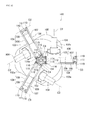
- Fig. 1 is a perspective view showing the entire configuration of the parallel mechanism robot 100 to which the non-contact holding device 1 is attached.
- Fig. 2 is a diagram showing the parallel mechanism robot 100 along a direction of an arrow A1 shown in Fig. 1 .
- the parallel mechanism robot 100 has a base part 102 in its upper part.
- the parallel mechanism robot 100 is supported by securing a flat attachment surface 102a (see Fig. 2 ), formed on a lower surface of the base part 102, to, for example, a horizontal ceiling or the like.
- the lower surface of the base part 102 is provided with three supporting members 103.
- Electric motors 104 are supported in the supporting members 103, respectively. Each of the electric motors 104 is supported in a manner that an axis line C2 of a motor shaft becomes parallel (i.e., horizontal) to the attachment surface 102a of the base part 102.
- the supporting members 103 are disposed at equal intervals (at every 120 degrees) around an axis line C1 extending along a perpendicular direction of the base part 102.
- the electric motors 104 also, are disposed at equal intervals (at every 120 degrees) around the axis line C1 extending along the perpendicular direction of the base part 102 (see Fig. 2 ).
- An arm supporting member 105 in the shape of a substantially hexagonal cylinder is secured to an output shaft of each electric motor 104 so as to be coaxial with the axis line C2. By driving each electric motor 104, the arm supporting member 105 rotates around the axis line C2.
- the electric motors 104 are connected to an electronic control device 130 that includes a motor driver. The electronic control device 130 controls the rotation of the output shafts of the electric motors 104.
- the parallel mechanism robot 100 has three arm main bodies 106. Each of the arm main bodies 106 is configured by a first arm 107 and a second arm 108.
- the first arm 107 is a long hollow tubular member made of, for example, carbon fiber reinforced plastic (CFRP) or the like. A base end part of each first arm 107 is attached to a side surface of the corresponding arm supporting member 105. The first arm 107 is secured such that an axis line thereof is perpendicular to the axis line C2 described above.
- CFRP carbon fiber reinforced plastic
- each first arm 107 is coupled to a base end part of the corresponding second arm 108.
- Each second arm 108 is configured so as to be able to swing around the free end part of the corresponding first arm 107.
- the second arm 108 is configured by a pair of long rods 109.
- the pair of rods 109 is disposed so as to become parallel to each other in a longitudinal direction thereof.
- Each of the rods 109 also is a long hollow tubular member made of, for example, carbon fiber reinforced plastic (CFRP) or the like.
- Base end parts of the rods 109 are coupled to the free end part of the first arm 107 by a pair of ball joints 110. Note that an axis line C3 that connects the ball joints 110 at the base end parts of the rods 109 is disposed so as to be parallel to the axis line C2 of each electric motor 104.
- One of the rods 109 and the other rod 109 are coupled to each other by a coupling member 111 in the vicinity of the base end part of each second arm 108. In the vicinity of the free end part of each second arm 108, one of the rods 109 and the other rod 109 are coupled to each other by a coupling member 112.
- the coupling members 111 and 112 each have, for example, an extension coil spring that functions as a biasing member in order to bias the pair of rods 109 in a mutually pulling direction.
- the coupling members 111 and 112 may have different structures, but, in terms of cutting costs, it is preferred that the coupling members 111 and 112 have the same structure.
- the both coupling members 111 and 112 function to prevent the rods 109 from rotating around the axis line parallel to the longitudinal direction.
- the parallel mechanism robot 100 also has a bracket 114 for attaching the non-contact holding device 1 (the detail thereof is described later) turnably thereto.
- the bracket 114 is a plate-like member having a substantially regular triangular shape.
- the bracket 114 is held by the three arm main bodies 106 in a manner that an attachment surface 114a (a lower surface of the bracket 114 in Fig. 1 ) of the bracket 114 to which the non-contact holding device 1 is attached becomes parallel (i.e., horizontal) to the attachment surface 102a of the base part 102.
- an attachment piece 115 is formed on each side of the bracket 114.
- the bracket 114 can swing around the free end parts of the arm main bodies 106 with respect to the arm main bodies 106. More specifically, end parts of the attachment pieces 115 of the bracket 114 are coupled to the free end parts of the rods 109 by ball joints 116.
- An axis line C4 (see Fig. 2 ) connecting a pair of ball joints 116 is parallel to the axis line C3 corresponding to each arm main body 106 due to the equal distance between the ball joint parts 110 and 116 of all the rods 109.
- the axis line C4 is parallel to the axis line C2 of each electric motor 104 as well.
- the bracket 114 swings with respect to each of the arm main bodies 106 by moving parallel to a horizontal plane. Then, the bracket 114 is supported by the three arm main bodies 106 so that the bracket 114 can move parallel to the horizontal plane in all of the sides of the substantially regular triangular bracket 114.
- the distance between the pair of ball joints 110 at the coupling part between each first arm 107 and each second arm 108 is set to be equal to the distance between the pair of ball joints 116 at the coupling part between each rod 109 of the second arm 108 and the bracket 114. Therefore, the pair of rods 109 configuring each second arm 108 is disposed so as to be always parallel to each other in the entire length of the longitudinal direction.
- the parallel mechanism robot 100 further has a pivot rod 120 extending downward from the base part 102 at the center of the base part 102, and an electric motor 121 for rotating the pivot rod 120.
- the electric motor 121 is secured to the base part 102 while having a shaft output thereof directed perpendicularly downward.
- One end part of the pivot rod 120 is coupled to the output shaft of the electric motor 121 via a universal coupling ("universal joint," hereinafter) 122 and a speed reducer 124 configured by a combination of a plurality of gears.
- the reduction ratio of the speed reducer 124 is 5.
- the other end part of the pivot rod 120 is connected to the non-contact holding device 1 via a universal joint 123.
- the non-contact holding device 1 and a lower connecting part of the universal joint 123 are rotatably secured to the bracket 114 by a bearing such that central axes thereof extend perpendicularly.
- the pivot rod 120 is realized by a rod 120a and a cylinder 120b, and configured to be able to stretch and retract freely.
- the pivot rod 120 is a ball spline that is capable of transmitting a rotary movement of the rod 120a to the cylinder 120b. Even when the bracket 114 is driven by the three electric motors 104 and moved to predetermined upper, lower, forward, rearward, left, or right position, adopting the universal joints 122, 123 for the both end parts of the pivot rod 120 can allow the pivot rod 120 to move based on the predetermined position.
- a configuration including the pivot rod 120 and the universal joints 122 and 123 is referred to as "pivot 125.”
- such machine elements as the speed reducer 124, the universal joint 122, the pivot rod 120 (the rod 120a and the cylinder 120b), and the universal joint 123 are connected in series between the electric motor 121 and the non-contact holding device 1, and rotary drive force of each electric motor 121 is transmitted to the non-contact holding device 1 through these serially connected machine elements.
- the electric motor 121 is connected to the electronic control device 130.
- a rotational angular position of the non-contact holding device 1 is controlled by controlling a rotary movement of the electric motor 121 by means of the electronic control device 130.
- the electronic control device 130 drives the arm main bodies 106 by controlling the three electric motors 104 to move the non-contact holding device 1 to a target position.
- the electronic control device 130 also drives the pivot rod 120 by controlling the electric motor 121 to rotate the non-contact holding device 1 to a target rotational angular position.
- a programmable logic controller PLC
- the electronic control device 130 is configured by a microprocessor for performing calculations, a ROM for storing a program for causing the microprocessor to execute processes, and a RAM for temporarily storing various data such as a calculation result.
- an input/output device 131 which functions as setting means for receiving an operational input from an operator and display means for displaying a status and settings of the parallel mechanism robot 100, is connected to the electronic control device 130.
- a touch panel display, a liquid crystal display, a keyboard or the like is favorably used as the input/output device 131.
- the operator can set control data of each of the electric motors 104, 121 by using the input/output device 131.
- the electronic control device 130 drives the electric motors 104 and the electric motor 121 by executing the programs stored in the ROM by using the set control data, and controls a position (x, y, z) in a three-dimensional space and rotational angle ( ⁇ ) of the non-contact holding device 1.
- Fig. 3 is a perspective view showing a bottom surface of the non-contact holding device 1.
- the non-contact holding device 1 has a Bernoulli chuck 20 that ejects high-pressure air to generate suction force for holding a workpiece 80 (see Fig. 8 , etc.) in a non-contact manner, a plurality of (eight, in the present embodiment) guide members 30 that are disposed at predetermined intervals around the Bernoulli chuck 20 and prevent the workpiece 80 from shifting laterally when the workpiece 80 is conveyed, and a chuck base (corresponding to the base member described in the patent claims) 10 to which the Bernoulli chuck 20 and the guide members 30 are attached.
- a Bernoulli chuck 20 that ejects high-pressure air to generate suction force for holding a workpiece 80 (see Fig. 8 , etc.) in a non-contact manner
- a plurality of (eight, in the present embodiment) guide members 30 that are disposed at predetermined intervals around the Bernoulli chuck 20 and prevent the workpiece 80 from shifting laterally when the workpiece 80 is conveye
- the chuck base 10 is a square plate-like member slightly larger than the workpiece 80 to be held.
- the chuck base 10 is formed of lightweight industrial plastic having the advantage of strength. It is preferred that the shape, size and the like of the chuck base 10 be set according to the shape and size of the workpiece to be held.
- An attachment 12 is attached to a center of an upper surface of the chuck base 10. This attachment 12 connects the chuck base 10 to the pivot rod 120 with the bracket 114 therebetween. The chuck base 10 can be turned by the pivot rod 120.
- the Bernoulli chuck 20 has a tubular main body 21 that is attached to a lower surface of the chuck base 10.
- a concave part 22 is formed on an end surface of the tubular main body 21.
- the Bernoulli chuck 20 is attached in a manner that an opened surface of the concave part 22 formed on the main body 21 faces the workpiece 80 to be held, i.e., in a manner that the opened surface of the concave part 22 faces downward.
- the opened surface of the main body 21 of the Bernoulli chuck 20 forms a workpiece holding surface for holding the workpiece 80 in a non-contact manner.
- a surface of the main body 21 that faces the concave part 22 has a plurality of ejection holes 23 (four ejection holes disposed at every 90 degrees in the present embodiment) for ejecting high-pressure air into the concave part 22.
- the ejection holes 23 penetrate obliquely downward through the main body 21, from a side surface of the main body 21 to a bottom surface of the concave part 22, so as to contact an inner circumferential surface of the concave part 22.
- An air pipe (not shown) is attached to each of the ejection holes 23.
- the air pipes are connected to an air pump (not shown) for supplying the high-pressure air.
- the high-pressure air When the high-pressure air is supplied from the air pump to the ejection holes 23 via the air pipes, the high-pressure air is ejected into the concave part 22 through the ejection holes 23.
- the ejected high-pressure air proceeds obliquely downward along the inner circumferential surface of the concave part 22 and is discharged from a gap between an opened end surface and the workpiece 80. Consequently, the flow speed of the high-pressure air increases when the high-air pressure enters the opened end surface from the inner circumferential surface of the concave part 22, reducing internal pressure of the concave part 22.
- the resultant negative pressure generates suction force on the workpiece 80.
- the Bernoulli chuck 20 functions as the non-contact holding unit described in the patent claims.
- the lower surface of the chuck base 10 is provided with a plurality of pin-like guide members 30 (eight, in the present embodiment) protruding vertically with respect to the chuck base 10.
- These eight guide members 30 are disposed at intervals around the Bernoulli chuck 20 so as to surround the workpiece 80 when the workpiece 80 is conveyed. More specifically, the guide members 30 are disposed in pairs (a total of four pairs) at intervals on the sides of the chuck base 10, such that a pair of guide members 30 faces the other with the Bernoulli chuck 20 therebetween.
- the guide members 30 are disposed so as to substantially abut with the held workpiece 80, i.e., so as to obtain a clearance of approximately 0.1 to 0.2 mm between each guide member 30 and each of the sides of the workpiece 80.
- the arrangement of the guide members 30 can be set according to the shape and the like of the workpiece 80.
- Each of the guide members 30 includes a tubular base end part 30a having one end attached to the chuck base 10, and a substantially conic tip end part 30b extending from the base end part 30a.
- the total length of each guide member 30 is set to be longer than the size in a height direction of the Bernoulli chuck 20.
- the tip end of each guide member 30 projects downward below the workpiece holding surface of the Bernoulli chuck 20.
- Each of the guide members 30 is formed of, for example, UHPE (Ultra High Molecular Weight Polyethylene), PEEK (polyether ether ketone), or polymer material in which these abovementioned materials are filled with PTFE (polytetrafluoroethylene) or the like to reduce friction.
- the guide members 30 facing each other are configured to be able to move away from each other.
- the guide members 30 move away from each other along guide holes 72 formed on the workpiece mounting tray 70, 71 as the non-contact holding device 1 (Bernoulli chuck 20) approaches a workpiece mounting surface 75 of the workpiece mounting tray 70, 71.
- the workpiece mounting tray 70, 71 corresponds to the workpiece mounting device described in the patent claims.
- the guide holes 72 each correspond to the guide part described in the patent claims.
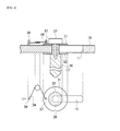
- FIG. 4 is a schematic diagram showing an enlargement of the movable mechanism of one of the guide members 30. Movable mechanisms of the rest of the guide members 30 have the same configuration.
- a long hole 11 extending perpendicular to each of the sides of the chuck base 10 is formed on an end part of each side of the chuck base 10.
- the guide member 30 is provided such that an upper end thereof penetrates through the long hole 11 and two washers 31, 32 that are provided above and below the chuck base 10 so as to hold the chuck base 10 therebetween.
- the guide member 30 and the washers 31, 32 are fastened to each other by means of a screw 33 at the upper end of the guide member 30. Therefore, the pin-like guide member 30 is attached to the long hole 11 in a manner that the guide member 30 can slide along the long hole 11 without coming off of the long hole 11.
- a torsion spring 34 is attached to the upper surface of the chuck base 10.
- the torsion spring 34 is disposed facing inward of the long hole 11 along an axis line of the long hole 11 so as to generate biasing force (tension force) in an internal direction along the direction of the axis line of the long hole 11.
- the torsion spring 34 has its one end latched to the upper surface of the chuck base 10 via a pin 36 and the other end to the washer 31 via a pin 37, the washer 31 being attached to the upper surface of the chuck base 10.
- the other end of the torsion spring 34 may be latched so as to be coaxial with a head part of the screw 33. In this manner, the torsion spring 34 applies the biasing force to the guide member 30 so as to bring the guide member 30 into abutment with one end (internal side) of the long hole 11.
- the guide member 30 By being biased by the torsion spring 34 as described above, the guide member 30 is brought into abutment with one end (internal side) of the long hole in the steady state. In other words, in the steady state, the guide member 30 is disposed so as to substantially abut with the held workpiece 80, i.e., so as to obtain a clearance of approximately 0.1 to 0.2 mm between each of the guide members 30 and each of the sides of the workpiece 80.
- the guide members 30 that face each other are forced to move away from each other along the long hole 11 (to the outside) by the guide holes 72 formed on the workpiece mounting tray 70, 71.
- the more the guide members 30 move away from each other along the long hole 11 the more the biasing force is applied by the torsion springs 34 to the guide members 30 to bring the guide members 30 close to each other.
- the guide members 30 facing each other are forced to move towards each other along the guide holes 72 of the workpiece mounting tray 70, 71 by the biasing force of the torsion springs 34 as the Bernoulli chuck 20 separates from the workpiece mounting surface of the workpiece mounting tray 70, 71. Consequently, the guide members 30 return to the steady positions thereof.
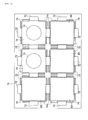
- Fig. 5 is a plan view of the workpiece mounting tray 70 on the removal side.
- Fig. 6 is a vertical cross-sectional diagram of the workpiece mounting tray 70, taken along line VI-VI of Fig. 5 .
- Fig. 7 is a plan view of the workpiece mounting tray 71 on the mounting side.
- the workpiece mounting tray 70 on the removal side has two workpiece mounting surfaces 75 so that two workpieces 80 can be mounted thereon.
- the workpiece mounting tray 71 on the other hand, has six (2 x 3) workpiece mounting surfaces 75 so that six workpieces 80 can be mounted thereon.
- Fig. 5 shows a state in which the workpiece 80 is mounted only on the workpiece mounting surface 75 to the left of the diagram.
- Fig. 6 shows a state in which the workpieces 80 are mounted on four workpiece mounting surfaces 75.
- the square workpiece mounting surfaces 75 for mounting the workpieces 80 thereon are formed on upper surfaces of the workpiece mounting trays 70, 71.
- the workpiece mounting surfaces 75 have substantially the same size as the workpieces 80.
- Each of the substantially rectangular guide holes 72 for guiding the guide members 30 is formed outside a substantially central part of each side of each workpiece mounting surface 75 along the side.
- An inner surface of each guide hole 72 includes an inclination part (inclination region) 72a inclining from an opening to the center of the hole and a perpendicular part (perpendicular region) 72b extending smoothly downward from the inclination part 72a.
- the guide holes 72 guide the guide members 30 such that the guide members 30 facing each other move away from each other along the inclination parts 72a as the Bernoulli chuck 20 descends and approaches the workpiece mounting surfaces 75.
- the guide holes 72 also guide the guide members 30 such that the guide members 30 facing each other come close to each other along the inclination parts 72a as the Bernoulli chuck 20 rises and moves away from the workpiece mounting surfaces 75. Two of the guide members 30 can enter a single guide hole 72.
- Both sides of each of the guide holes 72 of the workpiece mounting trays 70, 71 are provided with workpiece guiding protruding parts 74 having a trapezoidal cross section, along each side of each workpiece mounting surface 75.
- the workpiece guiding protruding parts 74 lead the workpiece 80 to a predetermined position.
- this workpiece 80 is led along inclined surfaces of the workpiece guiding protruding parts 74 and mounted on a predetermined position on the workpiece mounting surface 75.
- a circular through-hole 73 is formed at a central section of each workpiece mounting surface 75.
- the through-hole 73 is an air-bleeding hole that is supplied with air from below when the workpiece 80 is removed by the Bernoulli chuck 20, to prevent the workpiece mounting trays 70, 71 from being pulled by the negative pressure.
- FIG. 8 is a diagram for explaining how the guide members 30 are operated by the non-contact holding device 1, showing a time sequence of how the guide members 30 are moved when the Bernoulli chuck 20 removes the workpiece 80.
- the Bernoulli chuck 20 descends perpendicularly (arrow A2) to approach the workpiece mounting surface 75 of the workpiece mounting tray 70.
- the Bernoulli chuck 20 holds the workpiece 80 in a non-contact manner, while the guide members 30 facing each other are expanded by the guide holes 72. Consequently, the workpiece 80 can be held and removed, without having the guide members 30 contact the rim parts of the workpiece 80.
- the Bernoulli chuck 20 rises perpendicularly. As the Bernoulli chuck 20 moves away from the workpiece mounting surface 75 of the workpiece mounting tray 70, the guide members 30 facing each other are forced to move towards each other along the inner surfaces of the guide holes 72 of the workpiece mounting tray 70 by the biasing force of the torsion spring 34, to return to the steady positions.
- the workpiece 80 is suctioned and held by the Bernoulli chuck 20.
- the relative position between the workpiece 80 and the guide members 30 does not change in the height direction, but the clearance therebetween becomes narrow gradually.
- the workpiece 80 is restricted in lateral movement without being rubbed in an axial direction of the guide members 30. In this manner, the workpiece 80 is prevented from shifting laterally when being conveyed.
- Fig. 9 Here is described an example of a step of palletizing solar cell wafers (workpiece), wherein the non-contact holding device 1 (Bernoulli chuck 20) removes solar cell wafers 230 from the workpiece mounting tray 70 on the removal side and thereafter conveys the solar cell wafers 230 to the workpiece mounting tray 71 on the mounting side while adjusting rotational angular positions of the solar cell wafers 230.
- the series of operations between conveying the solar cell wafers 230 to removing the solar cell wafers 230 is same as or similar to the operations described hereinafter, except that the operations described hereinafter are carried out in reverse order; thus the descriptions thereof are omitted.
- Fig. 9 is a bird's eye view for explaining a brief outline of the step of palletizing the solar cells.
- a first conveyor 200 and second conveyor 201 are disposed parallel to each other, and the parallel mechanism robot 100 is installed above these two conveyors.
- Each of the first and second conveyors 200 and 201 repeatedly moves from the right-hand side of the diagram to the left-hand side at a predetermined speed or repeatedly moves and stops at a pitch.
- the solar cell wafers 230 are mounted on the workpiece mounting tray 70 on the removal side and flow on the first conveyor 200.
- Each of the solar cell wafers 230 is a square thin plate of, for example, 156 mm L x 156 mm W x 0.1 to 0.2 mm H.
- the solar cell wafers 230 are aligned and accommodated on the workpiece mounting tray 71 on the mounting side, which flows on the second conveyor 201.
- the workpiece mounting tray 71 on the mounting side has six (2 x 3) workpiece mounting surfaces 75 that are divided into cells.
- the solar cell wafers 230 that are mounted on the workpiece mounting tray 70 are transferred to the respective workpiece mounting surfaces 75 of the workpiece mounting tray 71 by the parallel mechanism robot 100.
- the parallel mechanism robot 100 drives the arm main bodies 106 to move the non-contact holding device 1 (the Bernoulli chuck 20) and approaches the solar cell wafers 230 mounted on the workpiece mounting tray 70. Thereafter, the parallel mechanism robot 100 removes the solar cell wafers 230 by means of the non-contact holding device 1 and conveys the solar cell wafers 230 to the workpiece mounting tray 71. The parallel mechanism robot 100 repeatedly executes these operations.
- the parallel mechanism robot 100 also aligns the orientation of each square solar cell wafer 230 with the orientation of each workpiece mounting surface 75 of the workpiece mounting tray 71 by rotating the non-contact holding device 1 when holding and conveying each solar cell wafer 230, and then accommodates the solar cell wafers 230 in the respective workpiece mounting surfaces 75 of the workpiece mounting tray 71.
- a first encoder 210 for detecting a moving distance of the first conveyor 200 is attached to the first conveyor 200.
- the first encoder 210 outputs the detected moving distance of the first conveyor 200 to the electronic control device 130.
- a second encoder 211 for detecting a moving distance of the second conveyor 201 is attached to the second conveyor 201.
- the second encoder 211 outputs the detected moving distance of the second conveyor 201 to the electronic control device 130.
- an imaging device 220 such as a CCD camera is provided above the first conveyor 200.
- the imaging device 220 captures an image of each solar cell wafer 230 mounted on the flowing workpiece mounting tray 70 to obtain the center of gravity and orientation (angle) of each solar cell wafer 230, and outputs the results to the electronic control device 130.
- an optical sensor 221 for detecting a leading end part of the workpiece mounting tray 71 is attached to the second conveyor 201.
- the optical sensor 221 outputs a detection signal to the electronic control device 130. Even when the workpiece mounting tray 70 flows on the first conveyor 200 at an irregular pitch or in any orientation (angle), the electronic control device 130 can appropriately control the position of the non-contact holding device 1 to remove the solar cell wafers 230, based on the rotation of the non-contact holding device 1 and the positions detected by the imaging device 220, as described above.
- the electronic control device 130 calculates the position of each solar cell wafer 230 based on the center of gravity of each solar cell wafer 230 and the moving distance of the first conveyor 200.
- the electronic control device 130 further calculates the position of the workpiece mounting tray 71 based on a detection signal of the leading end part of the workpiece mounting tray 71 and the moving distance of the second conveyor 201.
- the electronic control device 130 rotates the electric motors 104, drives the arm main bodies 106, accesses the solar cell wafers 230 from above, the solar cell wafers 230 being placed horizontally on the workpiece mounting tray 70, removes each solar cell wafer 230, conveys the removed solar cell wafer 230 within the space, accesses the workpiece mounting tray 71 from above, and mounts the held solar cell wafer 230 on the workpiece mounting tray 71 horizontally.
- the Bernoulli chuck 20 descends perpendicularly to approach the workpiece mounting surface 75 of the workpiece mounting tray 70. Subsequently, the guide members 30 come into contact with the inner surfaces of the guide holes 72. The guide members 30 facing each other are expanded gradually to move away from each other along the inclination parts 72a of the guide holes 72 as the Bernoulli chuck 20 descends and approaches the workpiece mounting surface 75. Then, while the guide members 30 are expanded by the guide holes 72, the Bernoulli chuck 20 holds the solar cell wafer 230 in a non-contact manner.
- the solar cell wafer 230 can be held and removed while keeping the guide members 30 away from the rim parts of the solar cell wafer 230.
- the guide members 30 facing each other are forced to move towards each other along the inner surfaces of the guide holes 72 of the workpiece mounting tray 70 by the biasing force of the torsion spring 34 as the Bernoulli chuck 20 rises and separates from the workpiece mounting surface 75 of the workpiece mounting tray 70.
- the guide members 30 then return to the steady positions thereof. In this manner, each of the solar cell wafers 230 can be prevented from shifting laterally when being conveyed.
- the Bernoulli chuck 20 holding the solar cell wafer 230 descends perpendicularly to approach the corresponding workpiece mounting surface 75 of the workpiece mounting tray 71. Thereafter, the guide members 30 come into contact with the inner surfaces of the guide holes 72. As the Bernoulli chuck 20 descends to approach the workpiece mounting surface 75, the guide members 30 facing each other are expanded gradually to move away from each other along the inclination parts 72a of the guide holes 72. Then, while the guide members 30 are expanded by the guide holes 72, the Bernoulli chuck 20 mounts the solar cell wafer 230 on the workpiece mounting surface 75 of the workpiece mounting tray 71.
- the solar cell wafer 230 can be mounted on the workpiece mounting surface 75 without having the guide members 30 contact the rim parts of the solar cell wafer 230.
- the guide members 30 facing each other are forced to move towards each other along the inner surfaces of the guide holes 72 of the workpiece mounting tray 71 by the biasing force of the torsion spring 34 as the Bernoulli chuck 20 separates from the workpiece mounting surface 75 of the workpiece mounting tray 71.
- the guide members 30 then return to the steady positions thereof.
- the electronic control device 130 drives the electric motor 121 to rotate the pivot (i.e., the non-contact holding device 1) based on the obtained orientation of each solar cell wafer 230, and aligns the orientation of each solar cell wafer 230 with the corresponding workpiece mounting surface 75 of the workpiece mounting tray 71.
- the solar cell wafers 230 that are mounted on the workpiece mounting tray 70 flowing on the first conveyor 200 are aligned and accommodated in the workpiece mounting tray 71 flowing on the second conveyor 201.
- the relative position between the non-contact holding device 1 and each of the workpiece mounting trays 70, 71 becomes slightly shifted due to the hand position accuracy of the parallel mechanism robot 100, the positional accuracies of the first and second conveyors 200 and 201, the detection position accuracy of the imaging device 220, and vibrations of various parts of the device.
- such shifting can be absorbed by expanding the guide members 30, whereby the solar cell wafers 230 can be removed or mounted without having the guide members 30 contact the rim parts of each solar cell wafer 230.
- the eight guide members 30 disposed around the Bernoulli chuck 20 move away from each other along the guide holes 72 of the workpiece mounting tray 70, 71 as the Bernoulli chuck 20 approaches the workpiece mounting surfaces 75 of the workpiece mounting tray 70, 71. Therefore, when removing or mounting the workpiece 80, each of the eight guide members 30 is expanded to the outside of the rim parts of the workpiece 80. As a result, the guide members 30 can be prevented from coming into contact with the rim parts of the workpiece 80 when the workpiece 80 is removed from the workpiece mounting tray 70 or mounted on the workpiece mounting tray 71. This can consequently prevent deterioration of the performance caused as a result of damage to the edges of the workpiece such as the solar cell wafer when, for example, removing or mounting the workpiece.
- the eight guide members 30 are disposed facing each other with the Bernoulli chuck 20 therebetween. Therefore, the workpiece 80 held by the Bernoulli chuck 20 can be effectively prevented from shifting laterally when being conveyed.
- the eight guide members 30, which are expanded when the workpiece 80 is removed, are forced to move towards each other by the biasing force of the torsion spring 34 as the Bernoulli chuck 20 separates from each workpiece mounting surface 75 of the workpiece mounting tray 70. Then, the guide members 30 are moved to the positions where the guide members 30 come into substantially abutment with the rim parts of the workpiece 80. Therefore, a lateral movement of the workpiece 80 can be restricted appropriately when the held workpiece 80 is conveyed.
- each of the guide members 30 is configured by the tubular base end part 30a and the conic tip end part 30b extending from the base end part 30a. With this configuration, the area of contact between each rim part of the workpiece 80 and the each guide member 30 can be reduced when conveying the workpiece 80. Also, the guide members 80 can be moved more smoothly when being guided to the guide holes 72 formed on each workpiece mounting tray 70, 71.
- the movable mechanism can be reduced in size and weight by using the torsion spring 34.
- the high-pressure air ejected from the Bernoulli chuck 20 is discharged from the gap between the Bernoulli chuck 20 and the workpiece 80, generating the Bernoulli effect.
- suction force is generated.
- the workpiece 80 can be held in a non-contact manner.
- the parallel mechanism robot 100 does not have an actuator in its movable part and therefore can keep the weight thereof low and can be driven at high speeds with a high degree of accuracy. Therefore, the base member 10 to which the Bernoulli chuck 20 and the guide members 30 are attached can be moved at extremely high speeds. Consequently, the use of the parallel mechanism robot 100 as the moving mechanism can transfer the workpiece 80 at high speeds while preventing the workpiece 80 from shifting laterally.
- the eight guide members 30 can be moved away from each other as the Bernoulli chuck 20 approaches each workpiece mounting surface 75. Therefore, when removing or mounting the workpiece 80, the eight guide members 30 can be expanded to the outside of the rim parts of the workpiece 80.
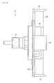
- Fig. 10 is a side view showing the configuration of the non-contact holding device 2.
- Fig. 11 is a perspective view showing a bottom surface of the non-contact holding device 2 holding the workpiece 80. Note that reference numerals same as or similar to those used in the first embodiment are used to indicate the same elements in Figs. 10 and 11 .
- the non-contact holding device 2 is different from the non-contact holding device 1 in having plate-like elastic guide members 40 in place of the pin-like guide members 30.
- the non-contact holding device 2 is also different from the non-contact holding device 1 in not having the movable mechanism shown in Fig. 4 .
- the rest of the configuration of the non-contact holding device 2 is the same as that of the non-contact holding device 1; thus, the explanation thereof is omitted.
- Not only the configuration of the non-contact holding device 2, but also a configuration of a parallel mechanism robot is described herein is the same as that of the parallel mechanism robot 100 of the first embodiment; thus, the explanation thereof is omitted.
- a lower surface of a chuck base 10A is provided with a plurality of plate-like guide members 40 (four, in the present embodiment) protruding vertically with respect to the lower surface of the chuck base 10A.
- These four guide members 40 are disposed at intervals around the Bernoulli chuck 20 so as to surround the workpiece 80 when the workpiece 80 is conveyed. More specifically, the guide members 40 are disposed on the sides of the chuck base 10A, such that the guide members 40 face each other with the Bernoulli chuck 20 therebetween.
- the guide members 40 are disposed so as to substantially abut with the held workpiece 80, i.e., so as to obtain a clearance of approximately 0.1 to 0.2 mm between each guide member 40 and each of the sides of the workpiece 80. It is preferred that the arrangement of the guide members 40 be set according to the shape and the like of the workpiece 80.
- each guide member 40 is set to be longer than the size in the height direction of the Bernoulli chuck 20.
- the tip end of each guide member 40 projects downward below the workpiece holding surface of the Bernoulli chuck 20.
- the inner side of the tip end part of each guide member 40 is beveled. For this reason, the tip end parts of the guide members 40 can smoothly come into contact with the inner surfaces of the guide holes 72.
- Each guide member 40 has a constant width (e.g., approximately 35 mm) along each outer rim of the workpiece 80.
- the guide members 40 are formed of an elastic body, such as fluororubber, urethane rubber, and silicon rubber.
- the surface of each guide member 40 may be coated with, for example, DLC (diamond-like carbon) in order to have a smooth surface with improved abrasion resistance.
- the lower end parts of the guide members 40 facing each other are configured to be able to deform (move) in a direction in which the guide members 40 separate from each other. Therefore, when removing the workpiece 80 from the workpiece mounting tray 70 on which the workpiece is disposed on the removal side or when mounting the held workpiece 80 on the workpiece mounting tray 71 on the mounting side, the guide members 40 facing each other are deformed such that the lower end parts of the guide members 40 bend and separate from each other along the guide holes 72 formed on the workpiece mounting tray 70, 71, as a non-contact holding device 2 (the Bernoulli chuck 20) approaches the workpiece mounting surface 75 of the workpiece mounting tray 70, 71.
- a non-contact holding device 2 the Bernoulli chuck 20
- each guide member 40 functions as the biasing member described in the patent claims.
- FIG. 12 is a diagram for explaining the movement of each of guide member 40 of the non-contact holding device 2.
- the Bernoulli chuck 20 descends perpendicularly to approach the workpiece mounting surface 75 of the workpiece mounting tray 70.
- the guide members 40 come into contact with the inner surfaces of the guide holes 72.
- the lower end parts of the guide members 40 gradually deform so as to separate from each other along the inclination parts 72a of the guide holes 72 as the Bernoulli chuck 20 descends to approach the workpiece mounting surface 75.
- the Bernoulli chuck 20 holds the workpiece 80 in a non-contact manner. Consequently, the workpiece 80 can be held and removed without having the guide members 40 contact the rim parts of the workpiece 80.
- the guide members 40 facing each other use their own restoring forces (biasing forces) to move towards each other along the inner surfaces of the guide holes 72 of the workpiece mounting tray 70 as the Bernoulli chuck 20 ascends perpendicularly to separate from the workpiece mounting surface 75 of the workpiece mounting tray 70.
- the guide members 40 return to the steady positions thereof. In this manner, the workpiece 80 is prevented from shifting laterally when being conveyed.
- each of the guide member 40 is formed from a plate-like elastic body. Therefore, when removing or mounting the workpiece 80, each of the four guide members 40 can be moved to the outside of each rim part of the workpiece 80 by means of the elasticity of the elastic body. In addition, the more the four guide members 40 deform so as to separate from each other, the stronger the biasing force acts on each of the guide members 40 to bring the guide members 40 close to each other by using the restoring force of each elastic body.
- each guide member 40 is in the shape of a plate having a constant width in the direction of each outer rim of the held workpiece 80. Therefore, the guide members 40 can be deformed and spread easily. Furthermore, the lateral movement of the workpiece 80 can be stably restricted when conveying the workpiece 80.
- the movable mechanism shown in Fig. 4 can be eliminated in the present embodiment, so that the structure can be simplified, thus achieving further reduction of the size, weight, and costs.
- the contact between the guide members 30, 40 and the guide holes 72 occurs in the section below the workpiece 80. Therefore, even when abrasion powder is generated due to friction therebetween, the abrasion powder can be inhibited from contaminating the workpiece 80 as long as the abrasion powder falls down. Moreover, the safety of the sliding part of each of the guide members 30, 40 is protected from the abrasion powder because the sliding parts do not come into directly contact with the workpiece 80. When the workpiece mounting device is used in a clean room, and even when the abrasion powder is generated and flows in the room, the section of the workpiece 80 above the sliding positions can be prevented from getting contaminated, because clean air flows downward.
- the present invention is not limited to these embodiments, and various modifications can be made to the present invention.
- the shape, size, number, and arrangement of the guide members 30, 40, the shape, size, and material of the base members 10, 10A, and the size, number, and arrangement of the Bernoulli chuck 20 are not particularly limited to those described in the embodiments and can be set according to the shape, size, and weight of the workpiece 80 to be held.
- the guide members are not necessarily disposed so as to face each other.
- three guide members may be disposed at every 120° around the circular workpiece.
- the guide holes of the workpiece mounting tray are formed depending on the arrangement of the guide members.
- the two pin-like guide members 30 enter one rectangular guide hole 72; however, the guide hole 72 may be divided into two circular or oval guide holes, and one pin-like guide member may be allowed to enter each of these guide holes.
- the tray (workpiece mounting tray 70, 71) for accommodating a single workpiece 80 in a horizontal manner is used as the workpiece mounting device for mounting the workpiece 80 thereon; however, a cassette for accommodating a stack of a plurality of workpieces 80 may be used in place of the tray.
Landscapes
- Container, Conveyance, Adherence, Positioning, Of Wafer (AREA)
- Manipulator (AREA)
- Engineering & Computer Science (AREA)
- Robotics (AREA)
Abstract
Description
- The present invention relates to a transfer device for transferring a workpiece, and a workpiece mounting device used along with the transfer device.
- In recent years, in order to transfer (picking and placing) a relatively thin workpiece such as a solar cell wafer or a lithium ion battery electrode, a transfer device that uses a non-contact holding device capable of holding a workpiece without directly contacting the workpiece has been used. As such a transfer device using a non-contact holding device,
Patent Literature 1 discloses a transporting device (a transfer device) that uses a Bernoulli chuck to generate suction force by ejecting high-pressure air. - The transfer device disclosed in
Patent Literature 1 removes a sheet-form board (workpiece) from a stage in the form of a flat plate and transfers the sheet-form board. The transfer device has a Bernoulli chuck functioning as suction means, and a control guide that is positioned so as to abut with an end part of the workpiece disposed on the flat stage and controls the position of the workpiece. This control guide includes a controller provided with an inclined surface, wherein the end part of the workpiece is brought into abutment with the inclined surface of the controller, thereby preventing Bernoulli chuck and the sheet-form workpiece from coming into contact with each other when the workpiece is suctioned by the Bernoulli chuck. The control guide further restricts a planar movement of the workpiece by means of the inclined surface of the controller when the workpiece is transported while being suctioned. - PTL 1: Japanese Patent Application Publication No.
2004-83180 - Incidentally, a solar cell wafer or a lithium ion battery electrode is thin in thickness and fragile as a workpiece. However, the transfer device disclosed in
Patent Literature 1 brings the end part of the sheet-form workpiece into abutment with the inclined surface of the controller as described above, to prevent the Bernoulli chuck and the sheet-form board from coming into contact with each other when the Bernoulli chuck suctions the sheet-form board. Therefore, there is a possibility that the sheet-form workpiece cracks or is damaged in different manners when the workpiece is removed from the flat stage. - In addition, if the sheet-form workpiece shifts relative to the positions of the Bernoulli chuck and the control guide when being removed from the flat stage in this transfer device disclosed in
Patent Literature 1, the inclined surface formed in the controller might rub a rim part of the workpiece. Rubbing and consequently damaging the rim part of the workpiece when removing and holding the workpiece (picking up) or mounting the workpiece (placing) results in deterioration of the performance of the solar cell wafer, which is the workpiece. - The present invention was contrived in order to solve the problems described above, and an object thereof is to provide a transfer device, capable of preventing a guide member from coming into contact with a rim part of a workpiece, the guide member preventing the workpiece from shifting laterally, when removing the workpiece from a workpiece mounting device and holding it and when mounting the held workpiece on the workpiece mounting device. The present invention also provides the workpiece mounting device used along with the transfer device.
- A transfer device according to the present invention has: a non-contact holding unit that holds a workpiece in a non-contact manner; a base member to which the non-contact holding unit is attached; a plurality of guide members that are disposed at intervals so as to surround the workpiece when the workpiece is conveyed and that are provided on the base member in a protruding manner; and a moving mechanism that moves the base member within a space, wherein the plurality of guide members are configured such that at least parts of the plurality of guide members can move away from each other, and wherein, when the workpiece is removed from a workpiece mounting device on which the workpiece is mounted or when the workpiece held by the non-contact holding unit is mounted on the workpiece mounting device, at least parts of the plurality of guide members move away from each other along a guide part formed in the workpiece mounting device, as the non-contact holding unit approaches a workpiece mounting surface of the workpiece mounting device.
- According to the transfer device of the present invention, the plurality of guide members disposed around the non-contact holding unit move away from each other along the guide part formed in the workpiece mounting device, as the non-contact holding unit approaches the workpiece mounting surface of the workpiece mounting device on which the workpiece is already mounted or about to be mounted. Therefore, the plurality of guide members are spread to the outside of a rim part of the workpiece when the workpiece is removed or mounted. As a result, the guide members can be prevented from coming into contact with the rim part of the workpiece, when the workpiece is removed from or mounted on the workpiece mounting device.
- In the transfer device according to the present invention, it is preferred that the plurality of guide members be disposed facing each other with the non-contact holding unit therebetween. By disposing the plurality of guide members in this fashion, the workpiece held by the non-contact holding unit can be effectively prevented from shifting laterally when being conveyed.
- It is preferred that the transfer device according to the present invention have a biasing member that applies biasing force to each of the guide members so as to bring the plurality of guide members close to each other as the plurality of guide members separate from each other, and that the plurality of guide members be moved towards each other by the biasing force of the biasing member, along the guide part formed on the workpiece mounting device, as the non-contact holding unit separates from the workpiece mounting surface of the workpiece mounting device.
- In this case, as the non-contact holding unit separates from the workpiece mounting surface of the workpiece mounting device, the plurality of guide members that are spread when the workpiece is removed, are moved towards each other by the biasing force of the biasing member so as to, for example, roughly abut with the rim part of the workpiece. This can appropriately prevent the held workpiece from moving laterally when being conveyed.
- In the transfer device according to the present invention, it is preferred that each of the guide members includes a tubular base end part and a conic tip end part extending from the base end part. With this configuration, the area of contact between the rim part of the workpiece and the each guide member can be reduced when conveying the workpiece. Also, the guide members can be moved more smoothly when being guided to the guide part formed in the workpiece mounting device.
- In the transfer device according to the present invention, it is preferred that the biasing member be a torsion spring. In this case, the biasing force can be applied to each of the guide members by using spring force of the torsion spring, so as to move the plurality of guide members towards each other as the guide members separate from each other. The use of the torsion spring enables reduction of the size and weight of the movable mechanism.
- In the transfer device according to the present invention, it is preferred that each of the guide members be formed from an elastic body. The elasticity of the elastic member can allow each of guide members to spread to the outside of the rim part of the workpiece when the workpiece is removed from or mounted on the workpiece mounting device. Moreover, restoring force of the elastic body can be used to apply each of the guide members with the biasing force that forces the plurality of guide members to move towards each other as the plurality of guide members deform to separate from each other.
- Here, it is preferred that each of the guide members be a plate-like member that has a constant width in a direction along an outer rim of the workpiece held by the non-contact holding device. Consequently, the guide members can be deformed and spread easily. Also, a lateral movement of the workpiece can be stably restricted when conveying the workpiece.
- In the transfer device according to the present invention, it is preferred that a Bernoulli chuck be used as the non-contact holding unit. In this case, high-pressure air that is ejected from the Bernoulli chuck is discharged from a gap between the Bernoulli chuck and the workpiece, generating a Bernoulli effect. As a result, suction force is generated. With the suction force, the workpiece can be held in a non-contact manner.
- In the transfer device according to the present invention, it is preferred that a parallel mechanism robot that moves the base member while keeping the base member horizontal via a plurality of links be used as the moving mechanism. The parallel mechanism robot does not have an actuator in its movable part and therefore can keep the weight thereof low and can be driven at high speeds with a high degree of accuracy. Therefore, the base member to which the non-contact holding unit and the guide members are attached can be moved at extremely high speeds. Consequently, the use of the parallel mechanism robot as the moving mechanism can transfer the workpiece at high speeds while preventing the workpiece from shifting laterally.
- The workpiece mounting device according to the present invention is used along with any of the transfer devices described above. This workpiece mounting device has a guide part that guides each of the plurality of guide members such that the guide members move away from each other as the non-contact holding unit configuring the transfer device approaches the workpiece mounting surface.
- The workpiece mounting device according to the present invention can allow the plurality of guide members, which are disposed around the non-contact holding unit, to move away from each other as the non-contact holding unit approaches the workpiece mounting surface, by guiding the plurality of guide members along the guide part. Thus, when removing the workpiece or mounting the workpiece, the plurality of guide members can be spread to the outside of the rim part of the workpiece.
- According to the present invention, each of the guide members, which prevents the workpiece from shifting laterally when being conveyed, can be prevented from coming into contact with the rim part of the workpiece when removing the workpiece from the workpiece mounting device and holding it or when mounting the workpiece on the workpiece mounting device.
-
- [
Fig. 1] Fig. 1 is a perspective view showing the entire configuration of a parallel mechanism robot of a first embodiment to which a non-contact holding device is attached. - [
Fig. 2] Fig. 2 is a diagram showing the parallel mechanism robot along a direction of an arrow A1 shown inFig. 1 . - [
Fig. 3] Fig. 3 is a perspective view showing a bottom surface of the non-contact holding device. - [
Fig. 4] Fig. 4 is a schematic diagram showing an enlargement of a movable mechanism of one of guide members of the non-contact holding device. - [
Fig. 5] Fig. 5 is a plan view of a workpiece mounting tray on the removal side. - [
Fig. 6] Fig. 6 is a cross-sectional diagram of the workpiece mounting tray on the removal side, the cross-sectional view being taken along line VI-VI ofFig. 5 . - [
Fig. 7] Fig. 7 is a plan view of a workpiece mounting tray on the mounting side. - [
Fig. 8] Fig. 8 is a diagram for explaining how the guide members are operated by the non-contact holding device. - [
Fig. 9] Fig. 9 is a bird's eye view for explaining a brief outline of a step of palletizing a solar cell wafer. - [
Fig. 10] Fig. 10 is a side view showing a configuration of a non-contact holding device according to a second embodiment. - [
Fig. 11] Fig. 11 is a perspective view showing a bottom surface of the non-contact holding device according to the second embodiment. - [
Fig. 12] Fig. 12 is a diagram for explaining a movement of each of guide members of the non-contact holding device according to the second embodiment. - Preferred embodiments of the present invention are described hereinafter in detail with reference to the drawings. The same reference numerals are used to indicate the same elements in each diagram, and therefore the overlapping explanations are omitted accordingly.
- First of all, the entire configuration of a parallel mechanism robot 100 (corresponding to the transfer device described in the patent claims) according to a first embodiment to which a
non-contact holding device 1 is attached is described with reference to bothFigs. 1 and2 .Fig. 1 is a perspective view showing the entire configuration of theparallel mechanism robot 100 to which thenon-contact holding device 1 is attached.Fig. 2 is a diagram showing theparallel mechanism robot 100 along a direction of an arrow A1 shown inFig. 1 . - The
parallel mechanism robot 100 has abase part 102 in its upper part. Theparallel mechanism robot 100 is supported by securing aflat attachment surface 102a (seeFig. 2 ), formed on a lower surface of thebase part 102, to, for example, a horizontal ceiling or the like. The lower surface of thebase part 102 is provided with three supportingmembers 103.Electric motors 104 are supported in the supportingmembers 103, respectively. Each of theelectric motors 104 is supported in a manner that an axis line C2 of a motor shaft becomes parallel (i.e., horizontal) to theattachment surface 102a of thebase part 102. The supportingmembers 103 are disposed at equal intervals (at every 120 degrees) around an axis line C1 extending along a perpendicular direction of thebase part 102. Theelectric motors 104, also, are disposed at equal intervals (at every 120 degrees) around the axis line C1 extending along the perpendicular direction of the base part 102 (seeFig. 2 ). - An
arm supporting member 105 in the shape of a substantially hexagonal cylinder is secured to an output shaft of eachelectric motor 104 so as to be coaxial with the axis line C2. By driving eachelectric motor 104, thearm supporting member 105 rotates around the axis line C2. Note that theelectric motors 104 are connected to anelectronic control device 130 that includes a motor driver. Theelectronic control device 130 controls the rotation of the output shafts of theelectric motors 104. - The
parallel mechanism robot 100 has three armmain bodies 106. Each of the armmain bodies 106 is configured by afirst arm 107 and asecond arm 108. Thefirst arm 107 is a long hollow tubular member made of, for example, carbon fiber reinforced plastic (CFRP) or the like. A base end part of eachfirst arm 107 is attached to a side surface of the correspondingarm supporting member 105. Thefirst arm 107 is secured such that an axis line thereof is perpendicular to the axis line C2 described above. - A free end part of each
first arm 107 is coupled to a base end part of the correspondingsecond arm 108. Eachsecond arm 108 is configured so as to be able to swing around the free end part of the correspondingfirst arm 107. Thesecond arm 108 is configured by a pair oflong rods 109. The pair ofrods 109 is disposed so as to become parallel to each other in a longitudinal direction thereof. Each of therods 109 also is a long hollow tubular member made of, for example, carbon fiber reinforced plastic (CFRP) or the like. Base end parts of therods 109 are coupled to the free end part of thefirst arm 107 by a pair of ball joints 110. Note that an axis line C3 that connects the ball joints 110 at the base end parts of therods 109 is disposed so as to be parallel to the axis line C2 of eachelectric motor 104. - One of the
rods 109 and theother rod 109 are coupled to each other by acoupling member 111 in the vicinity of the base end part of eachsecond arm 108. In the vicinity of the free end part of eachsecond arm 108, one of therods 109 and theother rod 109 are coupled to each other by acoupling member 112. Thecoupling members rods 109 in a mutually pulling direction. Thecoupling members coupling members coupling members rods 109 from rotating around the axis line parallel to the longitudinal direction. - The
parallel mechanism robot 100 also has abracket 114 for attaching the non-contact holding device 1 (the detail thereof is described later) turnably thereto. Thebracket 114 is a plate-like member having a substantially regular triangular shape. Thebracket 114 is held by the three armmain bodies 106 in a manner that anattachment surface 114a (a lower surface of thebracket 114 inFig. 1 ) of thebracket 114 to which thenon-contact holding device 1 is attached becomes parallel (i.e., horizontal) to theattachment surface 102a of thebase part 102. - In other words, an
attachment piece 115 is formed on each side of thebracket 114. By coupling eachattachment piece 115 to a free end part of each arm main body 106 (the free end part of each of the pair ofrods 109 configuring each second arm 108), thebracket 114 can swing around the free end parts of the armmain bodies 106 with respect to the armmain bodies 106. More specifically, end parts of theattachment pieces 115 of thebracket 114 are coupled to the free end parts of therods 109 by ball joints 116. An axis line C4 (seeFig. 2 ) connecting a pair of ball joints 116 is parallel to the axis line C3 corresponding to each armmain body 106 due to the equal distance between the balljoint parts rods 109. Therefore, the axis line C4 is parallel to the axis line C2 of eachelectric motor 104 as well. When each of the armmain bodies 106 is driven, thebracket 114 swings with respect to each of the armmain bodies 106 by moving parallel to a horizontal plane. Then, thebracket 114 is supported by the three armmain bodies 106 so that thebracket 114 can move parallel to the horizontal plane in all of the sides of the substantially regulartriangular bracket 114. - As described above, the distance between the pair of
ball joints 110 at the coupling part between eachfirst arm 107 and eachsecond arm 108 is set to be equal to the distance between the pair ofball joints 116 at the coupling part between eachrod 109 of thesecond arm 108 and thebracket 114. Therefore, the pair ofrods 109 configuring eachsecond arm 108 is disposed so as to be always parallel to each other in the entire length of the longitudinal direction. Because all the axis lines C2, C3, C4 are parallel to theattachment surface 102a of thebase part 102, theattachment surface 114a of thebracket 114, to which thenon-contact holding device 1 is attached, and theattachment surface 102a of thebase part 102 are kept parallel to each other even when each of the threefirst arms 107 turns around the axis line C2 in any way. - In response to a command from the
electronic control device 130, the position of rotation of thearm supporting member 105 fixed to the output shaft of eachelectric motor 104 is controlled. Consequently, the position of the free end part of eachfirst arm 107 is controlled. The position of the free end part of eachsecond arm 108 follows the controlled position of the free end part of eachfirst arm 107. As a result, the position of theattachment surface 114a of thebracket 114, to which thenon-contact holding device 1 is attached, is determined uniquely. At this moment, thebracket 114 moves while keeping its horizontal position, as described above. - The
parallel mechanism robot 100 further has apivot rod 120 extending downward from thebase part 102 at the center of thebase part 102, and anelectric motor 121 for rotating thepivot rod 120. Theelectric motor 121 is secured to thebase part 102 while having a shaft output thereof directed perpendicularly downward. One end part of thepivot rod 120 is coupled to the output shaft of theelectric motor 121 via a universal coupling ("universal joint," hereinafter) 122 and aspeed reducer 124 configured by a combination of a plurality of gears. Note that in the present embodiment the reduction ratio of thespeed reducer 124 is 5. The other end part of thepivot rod 120 is connected to thenon-contact holding device 1 via auniversal joint 123. Moreover, thenon-contact holding device 1 and a lower connecting part of theuniversal joint 123 are rotatably secured to thebracket 114 by a bearing such that central axes thereof extend perpendicularly. - The
pivot rod 120 is realized by arod 120a and acylinder 120b, and configured to be able to stretch and retract freely. Thepivot rod 120 is a ball spline that is capable of transmitting a rotary movement of therod 120a to thecylinder 120b. Even when thebracket 114 is driven by the threeelectric motors 104 and moved to predetermined upper, lower, forward, rearward, left, or right position, adopting theuniversal joints pivot rod 120 can allow thepivot rod 120 to move based on the predetermined position. Hereinafter, a configuration including thepivot rod 120 and theuniversal joints pivot 125." - In other words, such machine elements as the
speed reducer 124, theuniversal joint 122, the pivot rod 120 (therod 120a and thecylinder 120b), and theuniversal joint 123 are connected in series between theelectric motor 121 and thenon-contact holding device 1, and rotary drive force of eachelectric motor 121 is transmitted to thenon-contact holding device 1 through these serially connected machine elements. Theelectric motor 121 is connected to theelectronic control device 130. A rotational angular position of thenon-contact holding device 1 is controlled by controlling a rotary movement of theelectric motor 121 by means of theelectronic control device 130. - As described above, the
electronic control device 130 drives the armmain bodies 106 by controlling the threeelectric motors 104 to move thenon-contact holding device 1 to a target position. Theelectronic control device 130 also drives thepivot rod 120 by controlling theelectric motor 121 to rotate thenon-contact holding device 1 to a target rotational angular position. For example, a programmable logic controller (PLC), a dedicated control computer or the like can favorably be used as theelectronic control device 130. Theelectronic control device 130 is configured by a microprocessor for performing calculations, a ROM for storing a program for causing the microprocessor to execute processes, and a RAM for temporarily storing various data such as a calculation result. - Furthermore, an input/
output device 131, which functions as setting means for receiving an operational input from an operator and display means for displaying a status and settings of theparallel mechanism robot 100, is connected to theelectronic control device 130. Note that, for example, a touch panel display, a liquid crystal display, a keyboard or the like is favorably used as the input/output device 131. The operator can set control data of each of theelectric motors output device 131. Theelectronic control device 130 drives theelectric motors 104 and theelectric motor 121 by executing the programs stored in the ROM by using the set control data, and controls a position (x, y, z) in a three-dimensional space and rotational angle (θ) of thenon-contact holding device 1. - Next, a structure of the
non-contact holding device 1 attached to the other end of thepivot rod 120 via thebracket 114 is described with reference toFig. 3. Fig. 3 is a perspective view showing a bottom surface of thenon-contact holding device 1. - The
non-contact holding device 1 has aBernoulli chuck 20 that ejects high-pressure air to generate suction force for holding a workpiece 80 (seeFig. 8 , etc.) in a non-contact manner, a plurality of (eight, in the present embodiment)guide members 30 that are disposed at predetermined intervals around theBernoulli chuck 20 and prevent the workpiece 80 from shifting laterally when theworkpiece 80 is conveyed, and a chuck base (corresponding to the base member described in the patent claims) 10 to which theBernoulli chuck 20 and theguide members 30 are attached. - The
chuck base 10 is a square plate-like member slightly larger than theworkpiece 80 to be held. Thechuck base 10 is formed of lightweight industrial plastic having the advantage of strength. It is preferred that the shape, size and the like of thechuck base 10 be set according to the shape and size of the workpiece to be held. Anattachment 12 is attached to a center of an upper surface of thechuck base 10. Thisattachment 12 connects thechuck base 10 to thepivot rod 120 with thebracket 114 therebetween. Thechuck base 10 can be turned by thepivot rod 120. - The
Bernoulli chuck 20 has a tubularmain body 21 that is attached to a lower surface of thechuck base 10. Aconcave part 22 is formed on an end surface of the tubularmain body 21. TheBernoulli chuck 20 is attached in a manner that an opened surface of theconcave part 22 formed on themain body 21 faces theworkpiece 80 to be held, i.e., in a manner that the opened surface of theconcave part 22 faces downward. The opened surface of themain body 21 of theBernoulli chuck 20 forms a workpiece holding surface for holding theworkpiece 80 in a non-contact manner. - A surface of the
main body 21 that faces theconcave part 22 has a plurality of ejection holes 23 (four ejection holes disposed at every 90 degrees in the present embodiment) for ejecting high-pressure air into theconcave part 22. The ejection holes 23 penetrate obliquely downward through themain body 21, from a side surface of themain body 21 to a bottom surface of theconcave part 22, so as to contact an inner circumferential surface of theconcave part 22. An air pipe (not shown) is attached to each of the ejection holes 23. The air pipes are connected to an air pump (not shown) for supplying the high-pressure air. - When the high-pressure air is supplied from the air pump to the ejection holes 23 via the air pipes, the high-pressure air is ejected into the
concave part 22 through the ejection holes 23. The ejected high-pressure air proceeds obliquely downward along the inner circumferential surface of theconcave part 22 and is discharged from a gap between an opened end surface and theworkpiece 80. Consequently, the flow speed of the high-pressure air increases when the high-air pressure enters the opened end surface from the inner circumferential surface of theconcave part 22, reducing internal pressure of theconcave part 22. The resultant negative pressure generates suction force on theworkpiece 80. As a result, theworkpiece 80 is held in a non-contact manner. TheBernoulli chuck 20 functions as the non-contact holding unit described in the patent claims. - The lower surface of the
chuck base 10 is provided with a plurality of pin-like guide members 30 (eight, in the present embodiment) protruding vertically with respect to thechuck base 10. These eightguide members 30 are disposed at intervals around theBernoulli chuck 20 so as to surround theworkpiece 80 when theworkpiece 80 is conveyed. More specifically, theguide members 30 are disposed in pairs (a total of four pairs) at intervals on the sides of thechuck base 10, such that a pair ofguide members 30 faces the other with theBernoulli chuck 20 therebetween. In a steady state, theguide members 30 are disposed so as to substantially abut with the heldworkpiece 80, i.e., so as to obtain a clearance of approximately 0.1 to 0.2 mm between eachguide member 30 and each of the sides of theworkpiece 80. The arrangement of theguide members 30 can be set according to the shape and the like of theworkpiece 80. - Each of the
guide members 30 includes a tubularbase end part 30a having one end attached to thechuck base 10, and a substantially conictip end part 30b extending from thebase end part 30a. The total length of eachguide member 30 is set to be longer than the size in a height direction of theBernoulli chuck 20. The tip end of eachguide member 30 projects downward below the workpiece holding surface of theBernoulli chuck 20. Each of theguide members 30 is formed of, for example, UHPE (Ultra High Molecular Weight Polyethylene), PEEK (polyether ether ketone), or polymer material in which these abovementioned materials are filled with PTFE (polytetrafluoroethylene) or the like to reduce friction. - The
guide members 30 facing each other are configured to be able to move away from each other. When theworkpiece 80 is removed from a workpiece mounting tray 70 (seeFigs. 5 and6 ) on which theworkpiece 80 is disposed on the removal side or when the heldworkpiece 80 is mounted on a workpiece mounting tray 71 (seeFig. 7 ) on the mounting side, theguide members 30 move away from each other along guide holes 72 formed on theworkpiece mounting tray workpiece mounting surface 75 of theworkpiece mounting tray workpiece mounting tray - A movable mechanism of each
guide member 30 is now described with reference toFig. 4. Fig. 4 is a schematic diagram showing an enlargement of the movable mechanism of one of theguide members 30. Movable mechanisms of the rest of theguide members 30 have the same configuration. Along hole 11 extending perpendicular to each of the sides of thechuck base 10 is formed on an end part of each side of thechuck base 10. Theguide member 30 is provided such that an upper end thereof penetrates through thelong hole 11 and twowashers chuck base 10 so as to hold thechuck base 10 therebetween. Theguide member 30 and thewashers screw 33 at the upper end of theguide member 30. Therefore, the pin-like guide member 30 is attached to thelong hole 11 in a manner that theguide member 30 can slide along thelong hole 11 without coming off of thelong hole 11. - A
torsion spring 34 is attached to the upper surface of thechuck base 10. Thetorsion spring 34 is disposed facing inward of thelong hole 11 along an axis line of thelong hole 11 so as to generate biasing force (tension force) in an internal direction along the direction of the axis line of thelong hole 11. Thetorsion spring 34 has its one end latched to the upper surface of thechuck base 10 via apin 36 and the other end to thewasher 31 via apin 37, thewasher 31 being attached to the upper surface of thechuck base 10. The other end of thetorsion spring 34 may be latched so as to be coaxial with a head part of thescrew 33. In this manner, thetorsion spring 34 applies the biasing force to theguide member 30 so as to bring theguide member 30 into abutment with one end (internal side) of thelong hole 11. - By being biased by the
torsion spring 34 as described above, theguide member 30 is brought into abutment with one end (internal side) of the long hole in the steady state. In other words, in the steady state, theguide member 30 is disposed so as to substantially abut with the heldworkpiece 80, i.e., so as to obtain a clearance of approximately 0.1 to 0.2 mm between each of theguide members 30 and each of the sides of theworkpiece 80. On the other hand, when removing the workpiece 80 from theworkpiece mounting tray 70 described hereinafter or when mounting theworkpiece 80 on theworkpiece mounting tray 71, theguide members 30 that face each other are forced to move away from each other along the long hole 11 (to the outside) by the guide holes 72 formed on theworkpiece mounting tray guide members 30 move away from each other along thelong hole 11, the more the biasing force is applied by the torsion springs 34 to theguide members 30 to bring theguide members 30 close to each other. After theworkpiece 80 is removed from theworkpiece mounting tray 70 or after theworkpiece 80 is mounted on theworkpiece mounting tray 71, theguide members 30 facing each other are forced to move towards each other along the guide holes 72 of theworkpiece mounting tray Bernoulli chuck 20 separates from the workpiece mounting surface of theworkpiece mounting tray guide members 30 return to the steady positions thereof. - Next is described, with reference to
Figs. 5 to 7 , theworkpiece mounting trays parallel mechanism robot 100 attached with thenon-contact holding device 1 when theworkpiece 80 is mounted thereon.Fig. 5 is a plan view of theworkpiece mounting tray 70 on the removal side.Fig. 6 is a vertical cross-sectional diagram of theworkpiece mounting tray 70, taken along line VI-VI ofFig. 5 .Fig. 7 is a plan view of theworkpiece mounting tray 71 on the mounting side. Theworkpiece mounting tray 70 on the removal side on which theworkpiece 80 to be held is mounted and theworkpiece mounting tray 71 on the mounting side on which the heldworkpiece 80 is to be mounted, have the same configuration, except for the number ofworkpieces 80 that can be mounted. Incidentally, theworkpiece mounting tray 70 on the removal side has twoworkpiece mounting surfaces 75 so that twoworkpieces 80 can be mounted thereon. Theworkpiece mounting tray 71, on the other hand, has six (2 x 3)workpiece mounting surfaces 75 so that sixworkpieces 80 can be mounted thereon. Note thatFig. 5 shows a state in which theworkpiece 80 is mounted only on theworkpiece mounting surface 75 to the left of the diagram.Fig. 6 shows a state in which theworkpieces 80 are mounted on four workpiece mounting surfaces 75. - The square
workpiece mounting surfaces 75 for mounting theworkpieces 80 thereon are formed on upper surfaces of theworkpiece mounting trays workpiece mounting surfaces 75 have substantially the same size as theworkpieces 80. Each of the substantially rectangular guide holes 72 for guiding theguide members 30 is formed outside a substantially central part of each side of eachworkpiece mounting surface 75 along the side. An inner surface of eachguide hole 72 includes an inclination part (inclination region) 72a inclining from an opening to the center of the hole and a perpendicular part (perpendicular region) 72b extending smoothly downward from theinclination part 72a. The guide holes 72 guide theguide members 30 such that theguide members 30 facing each other move away from each other along theinclination parts 72a as theBernoulli chuck 20 descends and approaches the workpiece mounting surfaces 75. The guide holes 72 also guide theguide members 30 such that theguide members 30 facing each other come close to each other along theinclination parts 72a as theBernoulli chuck 20 rises and moves away from the workpiece mounting surfaces 75. Two of theguide members 30 can enter asingle guide hole 72. - Both sides of each of the guide holes 72 of the
workpiece mounting trays parts 74 having a trapezoidal cross section, along each side of eachworkpiece mounting surface 75. When theworkpiece 80 is mounted, the workpiece guiding protrudingparts 74 lead theworkpiece 80 to a predetermined position. In other words, when theworkpiece 80 held by theBernoulli chuck 20 is mounted, thisworkpiece 80 is led along inclined surfaces of the workpiece guiding protrudingparts 74 and mounted on a predetermined position on theworkpiece mounting surface 75. - Furthermore, a circular through-
hole 73 is formed at a central section of eachworkpiece mounting surface 75. The through-hole 73 is an air-bleeding hole that is supplied with air from below when theworkpiece 80 is removed by theBernoulli chuck 20, to prevent theworkpiece mounting trays - Next is described, with reference to
Fig. 8 , how each guidemember 30 moves when theworkpiece 80 is removed by theBernoulli chuck 20.Fig. 8 is a diagram for explaining how theguide members 30 are operated by thenon-contact holding device 1, showing a time sequence of how theguide members 30 are moved when theBernoulli chuck 20 removes theworkpiece 80. First, as shown in the top diagram ofFig. 8 , theBernoulli chuck 20 descends perpendicularly (arrow A2) to approach theworkpiece mounting surface 75 of theworkpiece mounting tray 70. - Subsequently, as shown in the middle diagram of
Fig. 8 , theguide members 30 come into contact with the inner surfaces of the guide holes 72. As theBernoulli chuck 20 descends to approach theworkpiece mounting surface 75, theguide members 30 facing each other are gradually expanded to move away from each other (arrows A3) along theinclination parts 72a of the guide holes 72. Therefore, each of theguide members 30 does not come into contact with a rim part of theworkpiece 80. - Then, as shown in the bottom diagram of
Fig. 8 , theBernoulli chuck 20 holds theworkpiece 80 in a non-contact manner, while theguide members 30 facing each other are expanded by the guide holes 72. Consequently, theworkpiece 80 can be held and removed, without having theguide members 30 contact the rim parts of theworkpiece 80. After removing theworkpiece 80, theBernoulli chuck 20 rises perpendicularly. As theBernoulli chuck 20 moves away from theworkpiece mounting surface 75 of theworkpiece mounting tray 70, theguide members 30 facing each other are forced to move towards each other along the inner surfaces of the guide holes 72 of theworkpiece mounting tray 70 by the biasing force of thetorsion spring 34, to return to the steady positions. Meanwhile, theworkpiece 80 is suctioned and held by theBernoulli chuck 20. The relative position between the workpiece 80 and theguide members 30 does not change in the height direction, but the clearance therebetween becomes narrow gradually. Thus, theworkpiece 80 is restricted in lateral movement without being rubbed in an axial direction of theguide members 30. In this manner, theworkpiece 80 is prevented from shifting laterally when being conveyed. - Next, operations of the
parallel mechanism robot 100 are described with reference toFig. 9 . Here is described an example of a step of palletizing solar cell wafers (workpiece), wherein the non-contact holding device 1 (Bernoulli chuck 20) removessolar cell wafers 230 from theworkpiece mounting tray 70 on the removal side and thereafter conveys thesolar cell wafers 230 to theworkpiece mounting tray 71 on the mounting side while adjusting rotational angular positions of thesolar cell wafers 230. Note that the series of operations between conveying thesolar cell wafers 230 to removing thesolar cell wafers 230 is same as or similar to the operations described hereinafter, except that the operations described hereinafter are carried out in reverse order; thus the descriptions thereof are omitted. Note thatFig. 9 is a bird's eye view for explaining a brief outline of the step of palletizing the solar cells. - First, a brief outline of the step of palletizing the
solar cell wafers 230 is described with reference toFig. 9 . In this step, afirst conveyor 200 andsecond conveyor 201 are disposed parallel to each other, and theparallel mechanism robot 100 is installed above these two conveyors. Each of the first andsecond conveyors solar cell wafers 230 are mounted on theworkpiece mounting tray 70 on the removal side and flow on thefirst conveyor 200. Each of thesolar cell wafers 230 is a square thin plate of, for example, 156 mm L x 156 mm W x 0.1 to 0.2 mm H. On the other hand, thesolar cell wafers 230 are aligned and accommodated on theworkpiece mounting tray 71 on the mounting side, which flows on thesecond conveyor 201. Theworkpiece mounting tray 71 on the mounting side has six (2 x 3)workpiece mounting surfaces 75 that are divided into cells. Thesolar cell wafers 230 that are mounted on theworkpiece mounting tray 70 are transferred to the respectiveworkpiece mounting surfaces 75 of theworkpiece mounting tray 71 by theparallel mechanism robot 100. - The
parallel mechanism robot 100 drives the armmain bodies 106 to move the non-contact holding device 1 (the Bernoulli chuck 20) and approaches thesolar cell wafers 230 mounted on theworkpiece mounting tray 70. Thereafter, theparallel mechanism robot 100 removes thesolar cell wafers 230 by means of thenon-contact holding device 1 and conveys thesolar cell wafers 230 to theworkpiece mounting tray 71. Theparallel mechanism robot 100 repeatedly executes these operations. Theparallel mechanism robot 100 also aligns the orientation of each squaresolar cell wafer 230 with the orientation of eachworkpiece mounting surface 75 of theworkpiece mounting tray 71 by rotating thenon-contact holding device 1 when holding and conveying eachsolar cell wafer 230, and then accommodates thesolar cell wafers 230 in the respectiveworkpiece mounting surfaces 75 of theworkpiece mounting tray 71. - More specifically, a
first encoder 210 for detecting a moving distance of thefirst conveyor 200 is attached to thefirst conveyor 200. Thefirst encoder 210 outputs the detected moving distance of thefirst conveyor 200 to theelectronic control device 130. On the other hand, asecond encoder 211 for detecting a moving distance of thesecond conveyor 201 is attached to thesecond conveyor 201. Thesecond encoder 211 outputs the detected moving distance of thesecond conveyor 201 to theelectronic control device 130. Furthermore, animaging device 220 such as a CCD camera is provided above thefirst conveyor 200. Theimaging device 220 captures an image of eachsolar cell wafer 230 mounted on the flowingworkpiece mounting tray 70 to obtain the center of gravity and orientation (angle) of eachsolar cell wafer 230, and outputs the results to theelectronic control device 130. In addition, an optical sensor 221 for detecting a leading end part of theworkpiece mounting tray 71 is attached to thesecond conveyor 201. The optical sensor 221 outputs a detection signal to theelectronic control device 130. Even when theworkpiece mounting tray 70 flows on thefirst conveyor 200 at an irregular pitch or in any orientation (angle), theelectronic control device 130 can appropriately control the position of thenon-contact holding device 1 to remove thesolar cell wafers 230, based on the rotation of thenon-contact holding device 1 and the positions detected by theimaging device 220, as described above. - The
electronic control device 130 calculates the position of eachsolar cell wafer 230 based on the center of gravity of eachsolar cell wafer 230 and the moving distance of thefirst conveyor 200. Theelectronic control device 130 further calculates the position of theworkpiece mounting tray 71 based on a detection signal of the leading end part of theworkpiece mounting tray 71 and the moving distance of thesecond conveyor 201. Based on the obtained positions of thesolar cell wafers 230 and the obtained position of theworkpiece mounting tray 71, theelectronic control device 130 rotates theelectric motors 104, drives the armmain bodies 106, accesses thesolar cell wafers 230 from above, thesolar cell wafers 230 being placed horizontally on theworkpiece mounting tray 70, removes eachsolar cell wafer 230, conveys the removedsolar cell wafer 230 within the space, accesses theworkpiece mounting tray 71 from above, and mounts the heldsolar cell wafer 230 on theworkpiece mounting tray 71 horizontally. - More specifically, when removing each
solar cell wafer 230 from theworkpiece mounting tray 70, theBernoulli chuck 20 descends perpendicularly to approach theworkpiece mounting surface 75 of theworkpiece mounting tray 70. Subsequently, theguide members 30 come into contact with the inner surfaces of the guide holes 72. Theguide members 30 facing each other are expanded gradually to move away from each other along theinclination parts 72a of the guide holes 72 as theBernoulli chuck 20 descends and approaches theworkpiece mounting surface 75. Then, while theguide members 30 are expanded by the guide holes 72, theBernoulli chuck 20 holds thesolar cell wafer 230 in a non-contact manner. Consequently, thesolar cell wafer 230 can be held and removed while keeping theguide members 30 away from the rim parts of thesolar cell wafer 230. After thesolar cell wafer 230 is removed by theBernoulli chuck 20, theguide members 30 facing each other are forced to move towards each other along the inner surfaces of the guide holes 72 of theworkpiece mounting tray 70 by the biasing force of thetorsion spring 34 as theBernoulli chuck 20 rises and separates from theworkpiece mounting surface 75 of theworkpiece mounting tray 70. Theguide members 30 then return to the steady positions thereof. In this manner, each of thesolar cell wafers 230 can be prevented from shifting laterally when being conveyed. - Similarly, when mounting each
solar cell wafer 230 on theworkpiece mounting tray 71, theBernoulli chuck 20 holding thesolar cell wafer 230 descends perpendicularly to approach the correspondingworkpiece mounting surface 75 of theworkpiece mounting tray 71. Thereafter, theguide members 30 come into contact with the inner surfaces of the guide holes 72. As theBernoulli chuck 20 descends to approach theworkpiece mounting surface 75, theguide members 30 facing each other are expanded gradually to move away from each other along theinclination parts 72a of the guide holes 72. Then, while theguide members 30 are expanded by the guide holes 72, theBernoulli chuck 20 mounts thesolar cell wafer 230 on theworkpiece mounting surface 75 of theworkpiece mounting tray 71. Consequently, thesolar cell wafer 230 can be mounted on theworkpiece mounting surface 75 without having theguide members 30 contact the rim parts of thesolar cell wafer 230. After thesolar cell wafer 230 is mounted by theBernoulli chuck 20, theguide members 30 facing each other are forced to move towards each other along the inner surfaces of the guide holes 72 of theworkpiece mounting tray 71 by the biasing force of thetorsion spring 34 as theBernoulli chuck 20 separates from theworkpiece mounting surface 75 of theworkpiece mounting tray 71. Theguide members 30 then return to the steady positions thereof. - Moreover, when conveying each
solar cell wafer 230, theelectronic control device 130 drives theelectric motor 121 to rotate the pivot (i.e., the non-contact holding device 1) based on the obtained orientation of eachsolar cell wafer 230, and aligns the orientation of eachsolar cell wafer 230 with the correspondingworkpiece mounting surface 75 of theworkpiece mounting tray 71. As a result of repeating these operations in real time, thesolar cell wafers 230 that are mounted on theworkpiece mounting tray 70 flowing on thefirst conveyor 200 are aligned and accommodated in theworkpiece mounting tray 71 flowing on thesecond conveyor 201. When removing thesolar cell wafers 230 from theworkpiece mounting tray 70 or when mounting thesolar cell wafers 230 on theworkpiece mounting tray 71, the relative position between thenon-contact holding device 1 and each of theworkpiece mounting trays parallel mechanism robot 100, the positional accuracies of the first andsecond conveyors imaging device 220, and vibrations of various parts of the device. According to the present embodiment, such shifting can be absorbed by expanding theguide members 30, whereby thesolar cell wafers 230 can be removed or mounted without having theguide members 30 contact the rim parts of eachsolar cell wafer 230. - According to the present embodiment, the eight
guide members 30 disposed around theBernoulli chuck 20 move away from each other along the guide holes 72 of theworkpiece mounting tray Bernoulli chuck 20 approaches theworkpiece mounting surfaces 75 of theworkpiece mounting tray workpiece 80, each of the eightguide members 30 is expanded to the outside of the rim parts of theworkpiece 80. As a result, theguide members 30 can be prevented from coming into contact with the rim parts of theworkpiece 80 when theworkpiece 80 is removed from theworkpiece mounting tray 70 or mounted on theworkpiece mounting tray 71. This can consequently prevent deterioration of the performance caused as a result of damage to the edges of the workpiece such as the solar cell wafer when, for example, removing or mounting the workpiece. - According to the present embodiment, the eight
guide members 30 are disposed facing each other with theBernoulli chuck 20 therebetween. Therefore, theworkpiece 80 held by theBernoulli chuck 20 can be effectively prevented from shifting laterally when being conveyed. - According to the present embodiment, the eight
guide members 30, which are expanded when theworkpiece 80 is removed, are forced to move towards each other by the biasing force of thetorsion spring 34 as theBernoulli chuck 20 separates from eachworkpiece mounting surface 75 of theworkpiece mounting tray 70. Then, theguide members 30 are moved to the positions where theguide members 30 come into substantially abutment with the rim parts of theworkpiece 80. Therefore, a lateral movement of theworkpiece 80 can be restricted appropriately when the heldworkpiece 80 is conveyed. - According to the present embodiment, each of the
guide members 30 is configured by the tubularbase end part 30a and the conictip end part 30b extending from thebase end part 30a. With this configuration, the area of contact between each rim part of theworkpiece 80 and the eachguide member 30 can be reduced when conveying theworkpiece 80. Also, theguide members 80 can be moved more smoothly when being guided to the guide holes 72 formed on eachworkpiece mounting tray - According to the present embodiment, the more the eight
guide members 30 are forced to move away from each other by the spring force of thetorsion spring 34, the stronger the biasing force applied to eachguide member 30 to bring theguide members 30 close to each other. The movable mechanism can be reduced in size and weight by using thetorsion spring 34. - According to the present embodiment, the high-pressure air ejected from the
Bernoulli chuck 20 is discharged from the gap between theBernoulli chuck 20 and theworkpiece 80, generating the Bernoulli effect. As a result, suction force is generated. With the suction force, theworkpiece 80 can be held in a non-contact manner. - The
parallel mechanism robot 100 does not have an actuator in its movable part and therefore can keep the weight thereof low and can be driven at high speeds with a high degree of accuracy. Therefore, thebase member 10 to which theBernoulli chuck 20 and theguide members 30 are attached can be moved at extremely high speeds. Consequently, the use of theparallel mechanism robot 100 as the moving mechanism can transfer theworkpiece 80 at high speeds while preventing the workpiece 80 from shifting laterally. - According to the
workpiece trays guide members 30 disposed around theBernoulli chuck 20 along the guide holes 72, the eightguide members 30 can be moved away from each other as theBernoulli chuck 20 approaches eachworkpiece mounting surface 75. Therefore, when removing or mounting theworkpiece 80, the eightguide members 30 can be expanded to the outside of the rim parts of theworkpiece 80. - The pin-
like guide members 30 are used in thenon-contact holding device 1 illustrated above; however, plate-like guide members can be used in place of the pin-like guide members 30. A configuration of anon-contact holding device 2 according to the second embodiment is described next with reference toFigs. 10 and11 .Fig. 10 is a side view showing the configuration of thenon-contact holding device 2.Fig. 11 is a perspective view showing a bottom surface of thenon-contact holding device 2 holding theworkpiece 80. Note that reference numerals same as or similar to those used in the first embodiment are used to indicate the same elements inFigs. 10 and11 . - The
non-contact holding device 2 is different from thenon-contact holding device 1 in having plate-likeelastic guide members 40 in place of the pin-like guide members 30. Thenon-contact holding device 2 is also different from thenon-contact holding device 1 in not having the movable mechanism shown inFig. 4 . The rest of the configuration of thenon-contact holding device 2 is the same as that of thenon-contact holding device 1; thus, the explanation thereof is omitted. Not only the configuration of thenon-contact holding device 2, but also a configuration of a parallel mechanism robot is described herein is the same as that of theparallel mechanism robot 100 of the first embodiment; thus, the explanation thereof is omitted. - A lower surface of a
chuck base 10A is provided with a plurality of plate-like guide members 40 (four, in the present embodiment) protruding vertically with respect to the lower surface of thechuck base 10A. These fourguide members 40 are disposed at intervals around theBernoulli chuck 20 so as to surround theworkpiece 80 when theworkpiece 80 is conveyed. More specifically, theguide members 40 are disposed on the sides of thechuck base 10A, such that theguide members 40 face each other with theBernoulli chuck 20 therebetween. In a steady state, theguide members 40 are disposed so as to substantially abut with the heldworkpiece 80, i.e., so as to obtain a clearance of approximately 0.1 to 0.2 mm between eachguide member 40 and each of the sides of theworkpiece 80. It is preferred that the arrangement of theguide members 40 be set according to the shape and the like of theworkpiece 80. - The height of each
guide member 40 is set to be longer than the size in the height direction of theBernoulli chuck 20. The tip end of eachguide member 40 projects downward below the workpiece holding surface of theBernoulli chuck 20. The inner side of the tip end part of eachguide member 40 is beveled. For this reason, the tip end parts of theguide members 40 can smoothly come into contact with the inner surfaces of the guide holes 72. Eachguide member 40 has a constant width (e.g., approximately 35 mm) along each outer rim of theworkpiece 80. Theguide members 40 are formed of an elastic body, such as fluororubber, urethane rubber, and silicon rubber. The surface of eachguide member 40 may be coated with, for example, DLC (diamond-like carbon) in order to have a smooth surface with improved abrasion resistance. - With elasticity thereof, the lower end parts of the
guide members 40 facing each other are configured to be able to deform (move) in a direction in which theguide members 40 separate from each other. Therefore, when removing the workpiece 80 from theworkpiece mounting tray 70 on which the workpiece is disposed on the removal side or when mounting the heldworkpiece 80 on theworkpiece mounting tray 71 on the mounting side, theguide members 40 facing each other are deformed such that the lower end parts of theguide members 40 bend and separate from each other along the guide holes 72 formed on theworkpiece mounting tray workpiece mounting surface 75 of theworkpiece mounting tray - At this moment, the more the
guide members 40 facing each other deform so as to separate from each other, the stronger the restoring force (biasing force) acts to bring theguide members 40 close to each other. Thus, after theworkpiece 80 is removed from theworkpiece mounting tray 70 or theworkpiece 80 is mounted on theworkpiece mounting tray 71, theguide members 40 facing each other are forced to move towards each other by their own restoring force (biasing forces) along the guide holes 72 of theworkpiece mounting tray Bernoulli chuck 20 separates from the workpiece mounting surface of theworkpiece mounting tray guide members 40 then return to the steady positions thereof. In other words, eachguide member 40 functions as the biasing member described in the patent claims. - Here is described, with reference to
Fig. 12 , how each guidemember 40 operates when theworkpiece 80 is removed by theBernoulli chuck 20.Fig. 12 is a diagram for explaining the movement of each ofguide member 40 of thenon-contact holding device 2. First, theBernoulli chuck 20 descends perpendicularly to approach theworkpiece mounting surface 75 of theworkpiece mounting tray 70. Thereafter, theguide members 40 come into contact with the inner surfaces of the guide holes 72. The lower end parts of theguide members 40 gradually deform so as to separate from each other along theinclination parts 72a of the guide holes 72 as theBernoulli chuck 20 descends to approach theworkpiece mounting surface 75. - Then, as shown in
Fig. 12 , while the lower end parts of theguide members 40 are deformed to be bent by the guide holes 72, theBernoulli chuck 20 holds theworkpiece 80 in a non-contact manner. Consequently, theworkpiece 80 can be held and removed without having theguide members 40 contact the rim parts of theworkpiece 80. After theworkpiece 80 is removed by theBernoulli chuck 20, theguide members 40 facing each other use their own restoring forces (biasing forces) to move towards each other along the inner surfaces of the guide holes 72 of theworkpiece mounting tray 70 as theBernoulli chuck 20 ascends perpendicularly to separate from theworkpiece mounting surface 75 of theworkpiece mounting tray 70. As a result, theguide members 40 return to the steady positions thereof. In this manner, theworkpiece 80 is prevented from shifting laterally when being conveyed. - According to the present embodiment, each of the
guide member 40 is formed from a plate-like elastic body. Therefore, when removing or mounting theworkpiece 80, each of the fourguide members 40 can be moved to the outside of each rim part of theworkpiece 80 by means of the elasticity of the elastic body. In addition, the more the fourguide members 40 deform so as to separate from each other, the stronger the biasing force acts on each of theguide members 40 to bring theguide members 40 close to each other by using the restoring force of each elastic body. - According to the present embodiment, each
guide member 40 is in the shape of a plate having a constant width in the direction of each outer rim of the heldworkpiece 80. Therefore, theguide members 40 can be deformed and spread easily. Furthermore, the lateral movement of theworkpiece 80 can be stably restricted when conveying theworkpiece 80. - The movable mechanism shown in
Fig. 4 can be eliminated in the present embodiment, so that the structure can be simplified, thus achieving further reduction of the size, weight, and costs. - In both the first embodiment and the second embodiment, the contact between the
guide members workpiece 80. Therefore, even when abrasion powder is generated due to friction therebetween, the abrasion powder can be inhibited from contaminating theworkpiece 80 as long as the abrasion powder falls down. Moreover, the safety of the sliding part of each of theguide members workpiece 80. When the workpiece mounting device is used in a clean room, and even when the abrasion powder is generated and flows in the room, the section of theworkpiece 80 above the sliding positions can be prevented from getting contaminated, because clean air flows downward. - The above has described embodiments of the present invention. However, the present invention is not limited to these embodiments, and various modifications can be made to the present invention. For instance, the shape, size, number, and arrangement of the
guide members base members Bernoulli chuck 20 are not particularly limited to those described in the embodiments and can be set according to the shape, size, and weight of theworkpiece 80 to be held. For example, when mounting a circular workpiece in place of a square workpiece, the guide members are not necessarily disposed so as to face each other. For example, three guide members may be disposed at every 120° around the circular workpiece. In this case, the guide holes of the workpiece mounting tray are formed depending on the arrangement of the guide members. - In the first embodiment, the two pin-
like guide members 30 enter onerectangular guide hole 72; however, theguide hole 72 may be divided into two circular or oval guide holes, and one pin-like guide member may be allowed to enter each of these guide holes. - Further, in the embodiments described above, the tray (
workpiece mounting tray 70, 71) for accommodating asingle workpiece 80 in a horizontal manner is used as the workpiece mounting device for mounting theworkpiece 80 thereon; however, a cassette for accommodating a stack of a plurality ofworkpieces 80 may be used in place of the tray. - Each of the embodiments above has described an example in which the
parallel mechanism robot 100 is applied to the step of palletizing thesolar cell wafers 230; however the scope of application of theparallel mechanism robot 100 is not limited to the step of palletizing thesolar cell wafers 230. -
- 1, 2 Non-contact holding device
- 10, 10A Chuck base
- 20 Bernoulli chuck
- 21 Main body
- 22 Concave part
- 23 Ejection hole
- 30, 40 Guide member
- 70, 71 Workpiece mounting tray
- 72 Guide hole
- 80 Workpiece
- 100 Parallel mechanism robot
Claims (20)
- A transfer device, comprising:a non-contact holding unit that holds a workpiece in a non-contact manner;a base member to which the non-contact holding unit is attached;a plurality of guide members that are disposed at intervals around the non-contact holding unit so as to surround the workpiece when the workpiece is conveyed and that are provided on the base member in a protruding manner; anda moving mechanism that moves the base member within a space, whereinthe plurality of guide members are configured such that at least parts of the plurality of guide members can move away from each other, and whereinwhen the workpiece is removed from a workpiece mounting device on which the workpiece is mounted or when the workpiece held by the non-contact holding unit is mounted on the workpiece mounting device, at least parts of the plurality of guide members move away from each other along a guide part formed in the workpiece mounting device, as the non-contact holding unit approaches a workpiece mounting surface of the workpiece mounting device.
- The transfer device according to claim 1, wherein the plurality of guide members are disposed facing each other with the non-contact holding unit therebetween.
- The transfer device according to claim 1, further comprising:a biasing member that applies biasing force to each of the guide members so as to bring the plurality of guide members close to each other as the plurality of guide members separate from each other, whereinthe plurality of guide members are moved towards each other by the biasing force of the biasing member, along the guide part formed on the workpiece mounting device, as the non-contact holding unit separates from the workpiece mounting surface of the workpiece mounting device.
- The transfer device according to claim 1, wherein each of the plurality of guide members includes a tubular base end part and a conic tip end part extending from the base end part.
- The transfer device according to claim 3, wherein the biasing member is a torsion spring.
- The transfer device according to claim 1, wherein each of the plurality of guide members is formed from an elastic body.
- The transfer device according to claim 6, wherein each of the plurality of guide members is a plate-like member that has a constant width in a direction along an outer rim of the workpiece to be held by the non-contact holding device.
- The transfer device according to claim 1, wherein the non-contact holding unit is a Bernoulli chuck.
- The transfer device according to claim 1, wherein the moving mechanism is a parallel mechanism robot that moves the base member while keeping the base member horizontal by means of a plurality of links.
- A workpiece mounting device used along with the transfer device according to claim 1,
the workpiece mounting device comprising:a guide part that guides each of the plurality of guide members such that the guide members move away from each other as the non-contact holding unit configuring the transfer device approaches the workpiece mounting surface. - The transfer device according to claim 2, further comprising:a biasing member that applies biasing force to each of the guide members so as to bring the plurality of guide members close to each other as the plurality of guide members separate from each other, whereinthe plurality of guide members are moved towards each other by the biasing force of the biasing member, along a guide part formed on the workpiece mounting device, as the non-contact holding unit separates from a workpiece mounting surface of the workpiece mounting device.
- The transfer device according to claim 2, wherein each of the plurality of guide members includes a tubular base end part and a conic tip end part extending from the base end part.
- The transfer device according to claim 3, wherein each of the plurality of guide members includes a tubular base end part and a conic tip end part extending from the base end part.
- The transfer device according to claim 2, wherein each of the plurality of guide members is formed from an elastic body.
- The transfer device according to claim 3, wherein each of the plurality of guide members is formed from an elastic body.
- The transfer device according to claim 2, wherein the non-contact holding unit is a Bernoulli chuck.
- The transfer device according to claim 3, wherein the non-contact holding unit is a Bernoulli chuck.
- The transfer device according to claim 2, wherein the moving mechanism is a parallel mechanism robot that moves the base member while keeping the base member horizontal by means of a plurality of links.
- The transfer device according to claim 3, wherein the moving mechanism is a parallel mechanism robot that moves the base member while keeping the base member horizontal by means of a plurality of links.
- A workpiece mounting device used along with the transfer device according to claim 3,
the workpiece mounting device comprising:a guide part that guides each of the plurality of guide members such that the guide members move away from each other as the non-contact holding unit configuring the transfer device approaches the workpiece mounting surface.
Applications Claiming Priority (2)
| Application Number | Priority Date | Filing Date | Title |
|---|---|---|---|
| JP2010037904A JP5488037B2 (en) | 2010-02-23 | 2010-02-23 | Transfer device and work placement device |
| PCT/JP2010/006307 WO2011104790A1 (en) | 2010-02-23 | 2010-10-26 | Transfer device, and workpiece mounting device |
Publications (2)
| Publication Number | Publication Date |
|---|---|
| EP2541592A1 true EP2541592A1 (en) | 2013-01-02 |
| EP2541592A4 EP2541592A4 (en) | 2014-06-25 |
Family
ID=44506238
Family Applications (1)
| Application Number | Title | Priority Date | Filing Date |
|---|---|---|---|
| EP10846458.7A Withdrawn EP2541592A4 (en) | 2010-02-23 | 2010-10-26 | TRANSFER DEVICE AND PART MOUNTING DEVICE |
Country Status (7)
| Country | Link |
|---|---|
| US (1) | US8882437B2 (en) |
| EP (1) | EP2541592A4 (en) |
| JP (1) | JP5488037B2 (en) |
| KR (1) | KR101389895B1 (en) |
| CN (1) | CN102770953B (en) |
| TW (1) | TWI464099B (en) |
| WO (1) | WO2011104790A1 (en) |
Cited By (2)
| Publication number | Priority date | Publication date | Assignee | Title |
|---|---|---|---|---|
| US10106336B2 (en) | 2012-12-25 | 2018-10-23 | Hirata Corporation | Transport system |
| EP3434633A1 (en) * | 2017-07-25 | 2019-01-30 | Toyo Jidoki Co., Ltd. | Pickup method and pickup device |
Families Citing this family (19)
| Publication number | Priority date | Publication date | Assignee | Title |
|---|---|---|---|---|
| CN202984936U (en) * | 2012-11-13 | 2013-06-12 | 富鼎电子科技(嘉善)有限公司 | Taking mechanism |
| CN103848173A (en) * | 2012-12-05 | 2014-06-11 | 施建强 | Precise linear feeding method and device |
| JP5929947B2 (en) * | 2014-02-28 | 2016-06-08 | 株式会社安川電機 | Suction pad, robot hand and robot |
| CN104057463B (en) * | 2014-06-23 | 2015-12-30 | 苏州博众精工科技有限公司 | A kind of pcb board jaw |
| WO2016052632A1 (en) | 2014-09-30 | 2016-04-07 | 株式会社カネカ | Sample transfer system and solar cell production method |
| CN111223965A (en) | 2016-05-06 | 2020-06-02 | 应用材料意大利有限公司 | Apparatus for manufacturing at least two solar cell arrangements |
| CN107346756A (en) * | 2016-05-06 | 2017-11-14 | 应用材料意大利有限公司 | Manufacture equipment, the system and method for at least two arrangements of solar cell part |
| JP6791665B2 (en) * | 2016-06-30 | 2020-11-25 | 日本電産サンキョー株式会社 | Transport system |
| JP6709692B2 (en) * | 2016-06-30 | 2020-06-17 | 日本電産サンキョー株式会社 | Robot, teaching jig, and robot teaching method |
| JP6496289B2 (en) * | 2016-09-29 | 2019-04-03 | ファナック株式会社 | Hand device |
| CN107962207B (en) * | 2017-10-27 | 2019-06-18 | 上海工程技术大学 | A mobile parallel drilling robot |
| CN108001936A (en) * | 2017-11-05 | 2018-05-08 | 安徽康乐机械科技有限公司 | Conveyer after inoculation |
| WO2019093341A1 (en) * | 2017-11-10 | 2019-05-16 | Agc株式会社 | Curved substrate production method and mold for curved substrate |
| JP6688470B2 (en) * | 2018-03-12 | 2020-04-28 | 株式会社安川電機 | Parallel link robot and parallel link robot system |
| JP7075814B2 (en) * | 2018-05-21 | 2022-05-26 | 株式会社荏原製作所 | Manufacturing method of substrate holding device, substrate polishing device, elastic member and substrate holding device |
| CN109877625B (en) * | 2019-02-19 | 2021-06-01 | 江苏鼎力起吊设备有限公司 | Air butt joint device |
| JP7486093B2 (en) * | 2019-11-12 | 2024-05-17 | パナソニックIpマネジメント株式会社 | Positioning device |
| US20210327731A1 (en) * | 2020-04-15 | 2021-10-21 | Advanced Semiconductor Engineering, Inc. | Mass transfer method, mass transfer device and buffer carrier |
| CA3204500A1 (en) * | 2021-02-05 | 2022-08-11 | Steven T. Charles | Direct drive robot for vitreoretinal surgery |
Family Cites Families (15)
| Publication number | Priority date | Publication date | Assignee | Title |
|---|---|---|---|---|
| JP2584310Y2 (en) * | 1992-10-20 | 1998-10-30 | エム・シー・エレクトロニクス株式会社 | IC inspection equipment |
| JP3640087B2 (en) * | 1994-11-29 | 2005-04-20 | 豊田工機株式会社 | Machine Tools |
| JPH08203983A (en) * | 1995-01-24 | 1996-08-09 | Advantest Corp | Small-sized device conveying positioning equipment |
| DE19755694C2 (en) * | 1997-12-16 | 2000-05-31 | Sez Semiconduct Equip Zubehoer | Handling device for thin, disc-shaped objects |
| KR100296759B1 (en) * | 1999-04-29 | 2001-07-12 | 정문술 | forking and un forking picker of shoting handler for burn-in tester |
| JP3806273B2 (en) * | 1999-09-17 | 2006-08-09 | 株式会社ジェイテクト | 4-DOF parallel robot |
| JP4632560B2 (en) * | 2000-03-01 | 2011-02-16 | シーグ パック システムズ アクチェンゲゼルシャフト | Robots that operate products in a three-dimensional space |
| JP4669252B2 (en) * | 2000-06-09 | 2011-04-13 | 株式会社ハーモテック | Swirl flow forming body and non-contact transfer device |
| JP2002011681A (en) * | 2000-06-23 | 2002-01-15 | Koganei Corp | Handling device |
| JP2002239965A (en) * | 2001-02-09 | 2002-08-28 | Hiroshi Akashi | Non-contact retainer with adjusting guide |
| EP1233442B1 (en) | 2001-02-20 | 2009-10-14 | Harmotec Corporation | Non-contacting conveyance equipment |
| DE20209440U1 (en) * | 2002-06-13 | 2002-08-29 | Sig Technology Ltd., Neuhausen Am Rheinfall | Device for moving and positioning an object in space |
| JP2004083180A (en) * | 2002-08-26 | 2004-03-18 | Sharp Corp | Transfer device and transfer method for sheet-like substrate |
| JP4526316B2 (en) * | 2004-07-16 | 2010-08-18 | 株式会社ディスコ | Workpiece transfer device |
| KR101343892B1 (en) * | 2008-06-10 | 2013-12-20 | 무라다기카이가부시끼가이샤 | Parallel Mechanism |
-
2010
- 2010-02-23 JP JP2010037904A patent/JP5488037B2/en not_active Expired - Fee Related
- 2010-10-26 CN CN201080064661.0A patent/CN102770953B/en not_active Expired - Fee Related
- 2010-10-26 EP EP10846458.7A patent/EP2541592A4/en not_active Withdrawn
- 2010-10-26 KR KR1020127019023A patent/KR101389895B1/en not_active Expired - Fee Related
- 2010-10-26 WO PCT/JP2010/006307 patent/WO2011104790A1/en not_active Ceased
- 2010-10-26 US US13/580,663 patent/US8882437B2/en not_active Expired - Fee Related
- 2010-12-27 TW TW099146062A patent/TWI464099B/en not_active IP Right Cessation
Cited By (2)
| Publication number | Priority date | Publication date | Assignee | Title |
|---|---|---|---|---|
| US10106336B2 (en) | 2012-12-25 | 2018-10-23 | Hirata Corporation | Transport system |
| EP3434633A1 (en) * | 2017-07-25 | 2019-01-30 | Toyo Jidoki Co., Ltd. | Pickup method and pickup device |
Also Published As
| Publication number | Publication date |
|---|---|
| EP2541592A4 (en) | 2014-06-25 |
| JP2011176053A (en) | 2011-09-08 |
| JP5488037B2 (en) | 2014-05-14 |
| KR101389895B1 (en) | 2014-04-30 |
| CN102770953A (en) | 2012-11-07 |
| CN102770953B (en) | 2015-04-08 |
| WO2011104790A1 (en) | 2011-09-01 |
| TW201139248A (en) | 2011-11-16 |
| TWI464099B (en) | 2014-12-11 |
| US20120313388A1 (en) | 2012-12-13 |
| US8882437B2 (en) | 2014-11-11 |
| KR20120112612A (en) | 2012-10-11 |
Similar Documents
| Publication | Publication Date | Title |
|---|---|---|
| US8882437B2 (en) | Transfer device, and workpiece mounting device | |
| JP7727046B2 (en) | Robot hand, robot and robot system | |
| TWI490155B (en) | A substrate transfer device, and a substrate transfer method | |
| JP5402542B2 (en) | Non-contact holding device and transfer device | |
| US10279485B2 (en) | Robot system and method of detecting deformation of end effector | |
| US20170106534A1 (en) | Transporter and transport method | |
| JP2015136785A (en) | Parallel link robot, parallel link robot hand and parallel link robot system | |
| CN107053252B (en) | robot | |
| KR20090094056A (en) | Work transfer system | |
| KR20110039455A (en) | Transfer facility and transfer method of plate work | |
| CN100410028C (en) | A four-degree-of-freedom hybrid pick-and-place robot mechanism capable of full rotation | |
| JPWO2016166952A1 (en) | Substrate transfer robot and its end effector | |
| CN106002930A (en) | Robot and robot system | |
| JP2011125967A (en) | Hand for wafer conveying robot, wafer conveying robot, and wafer conveying device | |
| CN107530890A (en) | Robot system and robot | |
| JP5913845B2 (en) | Conveying device and conveying method for plate member | |
| TW201617192A (en) | Robot and robot system | |
| JP2020536761A5 (en) | ||
| JP7167924B2 (en) | ROBOT HAND, ROBOT DEVICE, AND ELECTRONIC DEVICE MANUFACTURING METHOD | |
| JP5553254B2 (en) | Non-contact holding device and transfer device | |
| KR20190035845A (en) | Manufacturing method of glass plate and apparatus for manufacturing glass plate | |
| CN209973698U (en) | Manipulator carrying device | |
| JP5827046B2 (en) | Plate member support device and support method, and plate member transport device | |
| JP2020163479A (en) | De-palletize apparatus and de-palletize method | |
| JP2012142491A (en) | Transfer apparatus and work-piece pick up method |
Legal Events
| Date | Code | Title | Description |
|---|---|---|---|
| PUAI | Public reference made under article 153(3) epc to a published international application that has entered the european phase |
Free format text: ORIGINAL CODE: 0009012 |
|
| 17P | Request for examination filed |
Effective date: 20120822 |
|
| AK | Designated contracting states |
Kind code of ref document: A1 Designated state(s): AL AT BE BG CH CY CZ DE DK EE ES FI FR GB GR HR HU IE IS IT LI LT LU LV MC MK MT NL NO PL PT RO RS SE SI SK SM TR |
|
| DAX | Request for extension of the european patent (deleted) | ||
| A4 | Supplementary search report drawn up and despatched |
Effective date: 20140527 |
|
| RIC1 | Information provided on ipc code assigned before grant |
Ipc: H01L 21/687 20060101ALI20140521BHEP Ipc: B65G 49/06 20060101ALI20140521BHEP Ipc: H01L 21/677 20060101AFI20140521BHEP |
|
| STAA | Information on the status of an ep patent application or granted ep patent |
Free format text: STATUS: THE APPLICATION IS DEEMED TO BE WITHDRAWN |
|
| 18D | Application deemed to be withdrawn |
Effective date: 20160503 |