EP2541320A1 - Imaging prevention device, imaging prevention method and image display system - Google Patents
Imaging prevention device, imaging prevention method and image display system Download PDFInfo
- Publication number
- EP2541320A1 EP2541320A1 EP11747502A EP11747502A EP2541320A1 EP 2541320 A1 EP2541320 A1 EP 2541320A1 EP 11747502 A EP11747502 A EP 11747502A EP 11747502 A EP11747502 A EP 11747502A EP 2541320 A1 EP2541320 A1 EP 2541320A1
- Authority
- EP
- European Patent Office
- Prior art keywords
- infrared light
- camcording
- video image
- wavelength
- image display
- Prior art date
- Legal status (The legal status is an assumption and is not a legal conclusion. Google has not performed a legal analysis and makes no representation as to the accuracy of the status listed.)
- Withdrawn
Links
Images



Classifications
-
- H—ELECTRICITY
- H04—ELECTRIC COMMUNICATION TECHNIQUE
- H04N—PICTORIAL COMMUNICATION, e.g. TELEVISION
- H04N5/00—Details of television systems
- H04N5/76—Television signal recording
- H04N5/91—Television signal processing therefor
- H04N5/913—Television signal processing therefor for scrambling ; for copy protection
-
- G—PHYSICS
- G03—PHOTOGRAPHY; CINEMATOGRAPHY; ANALOGOUS TECHNIQUES USING WAVES OTHER THAN OPTICAL WAVES; ELECTROGRAPHY; HOLOGRAPHY
- G03B—APPARATUS OR ARRANGEMENTS FOR TAKING PHOTOGRAPHS OR FOR PROJECTING OR VIEWING THEM; APPARATUS OR ARRANGEMENTS EMPLOYING ANALOGOUS TECHNIQUES USING WAVES OTHER THAN OPTICAL WAVES; ACCESSORIES THEREFOR
- G03B11/00—Filters or other obturators specially adapted for photographic purposes
-
- G—PHYSICS
- G03—PHOTOGRAPHY; CINEMATOGRAPHY; ANALOGOUS TECHNIQUES USING WAVES OTHER THAN OPTICAL WAVES; ELECTROGRAPHY; HOLOGRAPHY
- G03B—APPARATUS OR ARRANGEMENTS FOR TAKING PHOTOGRAPHS OR FOR PROJECTING OR VIEWING THEM; APPARATUS OR ARRANGEMENTS EMPLOYING ANALOGOUS TECHNIQUES USING WAVES OTHER THAN OPTICAL WAVES; ACCESSORIES THEREFOR
- G03B21/00—Projectors or projection-type viewers; Accessories therefor
- G03B21/14—Details
- G03B21/26—Projecting separately subsidiary matter simultaneously with main image
-
- G—PHYSICS
- G03—PHOTOGRAPHY; CINEMATOGRAPHY; ANALOGOUS TECHNIQUES USING WAVES OTHER THAN OPTICAL WAVES; ELECTROGRAPHY; HOLOGRAPHY
- G03B—APPARATUS OR ARRANGEMENTS FOR TAKING PHOTOGRAPHS OR FOR PROJECTING OR VIEWING THEM; APPARATUS OR ARRANGEMENTS EMPLOYING ANALOGOUS TECHNIQUES USING WAVES OTHER THAN OPTICAL WAVES; ACCESSORIES THEREFOR
- G03B21/00—Projectors or projection-type viewers; Accessories therefor
- G03B21/54—Accessories
- G03B21/56—Projection screens
-
- H—ELECTRICITY
- H04—ELECTRIC COMMUNICATION TECHNIQUE
- H04N—PICTORIAL COMMUNICATION, e.g. TELEVISION
- H04N21/00—Selective content distribution, e.g. interactive television or video on demand [VOD]
- H04N21/80—Generation or processing of content or additional data by content creator independently of the distribution process; Content per se
- H04N21/83—Generation or processing of protective or descriptive data associated with content; Content structuring
- H04N21/835—Generation of protective data, e.g. certificates
- H04N21/8358—Generation of protective data, e.g. certificates involving watermark
-
- H—ELECTRICITY
- H04—ELECTRIC COMMUNICATION TECHNIQUE
- H04N—PICTORIAL COMMUNICATION, e.g. TELEVISION
- H04N9/00—Details of colour television systems
- H04N9/12—Picture reproducers
- H04N9/31—Projection devices for colour picture display, e.g. using electronic spatial light modulators [ESLM]
- H04N9/3102—Projection devices for colour picture display, e.g. using electronic spatial light modulators [ESLM] using two-dimensional electronic spatial light modulators
-
- H—ELECTRICITY
- H04—ELECTRIC COMMUNICATION TECHNIQUE
- H04N—PICTORIAL COMMUNICATION, e.g. TELEVISION
- H04N5/00—Details of television systems
- H04N5/76—Television signal recording
- H04N5/91—Television signal processing therefor
- H04N5/913—Television signal processing therefor for scrambling ; for copy protection
- H04N2005/91392—Television signal processing therefor for scrambling ; for copy protection using means for preventing making copies of projected video images
-
- H—ELECTRICITY
- H04—ELECTRIC COMMUNICATION TECHNIQUE
- H04N—PICTORIAL COMMUNICATION, e.g. TELEVISION
- H04N21/00—Selective content distribution, e.g. interactive television or video on demand [VOD]
- H04N21/80—Generation or processing of content or additional data by content creator independently of the distribution process; Content per se
- H04N21/83—Generation or processing of protective or descriptive data associated with content; Content structuring
- H04N21/835—Generation of protective data, e.g. certificates
Definitions
- JP2002-341449A discloses an anti-camcording technique of providing a low-power infrared light projecting means before or behind a screen on which an image content is projected, so that infrared light is projected toward an audience.
- JP2010-20263A discloses a technique of providing an infrared light projecting means behind a screen on which an image content is projected, and emitting light having a central wavelength of 800 nm to 980 nm as infrared light toward a camera.
- the present invention provides a means that, by superposing infrared light on an image content such as a movie in a movie theater, a play theater, or the like, surely degrades image quality of an illegally camcorded video image, while causing eyes of an audience in good faith not to sense degradation of image quality.
- An anti-camcording device of the present invention is an anti-camcording device that project infrared light so that infrared light is superposed on a video image displayed on a video image display section, so as to interfere with illegal camcording of the video image displayed on the video image display section, and the anti-camcording device includes: an infrared light source that emits infrared light containing at least light of a wavelength of 780 nm or more, toward the video image display section; and a wavelength cut filter provided before the infrared light source, which substantially does not transmit a predetermined wavelength component of the infrared light, the predetermined wavelength component being a component of a wavelength of 780 nm to 840 nm.
- a video image display device or a video image display method of the present invention it is possible to degrade display quality of illegally camcorded image contents, without degrading display quality of video images displayed on a video image display section. Therefore, it is possible to make the illegally camcorded image contents useless, and consequently to prevent unauthorized distribution of illegally camcorded image contents.
- infrared light when infrared light is superposed on the video image display section, infrared light is not visually recognized as coloration light by eyes of humans, and the infrared light is added as an image (anti-camcording signal) that interferes with the original video image in the illegally camcorded image content.
- the display quality of the illegally camcorded image can be effectively degraded.
- the display quality of illegally camcorded video images can be degraded, without degradation of display quality of video images displayed on the video image display section. Therefore, the illegally camcorded image contents are made useless, and consequently, unclear distribution of illegally camcorded image contents can be prevented.
- the aforementioned predetermined wavelength component preferably has a wavelength lower than a wavelength at which a luminance of the infrared light source becomes maximum. More specifically, for example, the predetermined wavelength component is preferably a component of 780 nm to 840 nm, or alternatively, the predetermined wavelength component is preferably a component of 780 nm to 870 nm.
- This configuration makes it possible to surely and effectively exert an interference effect against an illegally camcording camera, while avoiding a coloring phenomenon due to infrared light.
- the wavelength cut filter desirably has a characteristic of having a continuous change of 30 dB or more in a transition range between a light transmission range and a light blocking range.
- a wavelength range in which an attenuation amount continuously changes for 30 dB or more in the transition band preferably exists between an upper limit wavelength of the above-described predetermined wavelength component and the wavelength at which the infrared light source provides a maximum luminance.
- This configuration makes it possible to sufficiently cut off light in a wavelength range that can be visually recognized by eyes of humans. Therefore, it is possible to provide an anti-camcording device having excellent characteristics, without causing coloration in image contents.
- the wavelength at which the infrared light source provides the maximum luminance is desirably 920 nm or less.
- This configuration causes infrared light to be visibly sensed as a noise on an image illegally camcorded by a usual digital camera, video camera, or the like, thereby degrading the illegally camcorded image.
- the infrared light further desirably has a luminance of 0.310 nmW/cm 2 or more at the predetermined position before the video image display section.
- This configuration makes it possible to avoid harmfully affecting an audience in good faith even if infrared light is projected toward the audience in a movie theater or the like, and therefore, makes it possible to provide a safe anti-camcording device.
- a ratio of a luminance of the infrared light with respect to a luminance of a video image displayed on the video image display section is desirably 0.012 or more at an arbitrary position before the surface of the video image display section.
- This configuration makes it possible to adjust infrared light at an arbitrary position before the front surface of the screen when an anti-camcording device is installed. Therefore, this makes it possible to simplify operation steps required for the installation, and to provide an anti-camcording device with which an anti-camcording effect can be achieved surely.
- the ratio of a luminance of the infrared light with respect to a luminance of a video image displayed on the video image display section is desirably 0.59 or more at an arbitrary position before the surface of the video image display section.
- This configuration makes it possible to adjust infrared light at an arbitrary position before the front surface of the screen when an anti-camcording device is installed. Therefore, this makes it possible to simplify operation steps required for the installation, and to provide an anti-camcording device with which an anti-camcording effect can be achieved more surely.
- the infrared light source is desirably any one of an LED, a laser, and a xenon lamp.
- an anti-camcording device can be produced at low costs.
- the infrared light source may be a light source that emits light having a visible light wavelength.
- a light source that emits light containing a visible light component may be used as the infrared light source. In this case, however, it is desirable to use a filter that cuts off a visible light component in combination.
- a plurality of the infrared light sources are provided.
- the anti-camcording device of the present invention is an anti-camcording device that projects infrared light so that the infrared light is superposed on a video image displayed on a video image display section, so as to interfere with illegal camcording of the video image displayed on the video image display section
- the anti-camcording device includes an infrared light source that emits infrared light containing light of a wavelength of 780 nm or more, wherein the infrared light emitted by the infrared light source and projected to the video image display section has a luminance with which the infrared light is substantially invisible to eyes of humans in a wavelength range of 780 nm to 840 nm, and has a luminance with which the infrared light is visible on an image obtained by camcording the video image with use of a camera, at a wavelength at which the luminance becomes maximum.
- the anti-camcording method of the present invention it is possible to degrade image quality of illegally camcorded video images, without degrading display quality of video images displayed on the video image display section. Therefore, the illegally camcorded image contents can be made useless, and consequently, unclear distribution of illegally camcorded image contents can be prevented.
- infrared light is projected so that the infrared light is superposed on a video image displayed on the video image display section so as to interfere with the illegally camcording of the video image displayed on the video image display section, wherein the infrared light, in a wavelength range of 780 nm to 840 nm, is substantially unrecognizable to eyes of humans who observe the video image display section, and at a wavelength at which the infrared light has a maximum luminance, the infrared light is visually recognized on an image obtained by camcording the video image with use of a camera.
- Inventors of the present invention focused attention on the following point: whereas light other than visible light, such as infrared rays or ultraviolet rays, is hardly recognized visually by humans, wavelengths out of the visible light region such as infrared rays, ultraviolet rays, etc. are also detected as noises by CCD and CMOS image sensors as image pickup elements of digital cameras and digital video cameras used in illegal camcording, due to instability; specification, etc. of elements themselves.
- the inventors found that when video images are being displayed on a screen in a movie theater or the like, light having a waveform difficult for humans to recognize could be emitted as anti-camcording signals at the same time, from the image display surface, so that the above-mentioned anti-camcording signals can be captured as perceivable signals in an image content illegally camcorded by a video camera or the like.
- the inventors completed the present invention.
- an image based on anti-camcording signals is recognized visually as a noise that interferes with an original video image, whereby quality of the illegally camcorded image content can be degraded. This makes viewing of the video image difficult, thereby consequently preventing unclear distribution of illegally camcorded image contents.
- the present embodiment is a video image display system for screening video images such as movies in a movie theater or a play theater.
- the video image display system of the present embodiment in the case where an image content such as a movie screened in a theater is camcorded with a video camera, a camera mounted on a portable terminal, or the like, the display quality of the thus camcorded digital image content is degraded to a level at which the content is unwatchable, whereby unauthorized distribution of illegally camcorded image contents can be prevented.
- FIG. 1 shows a schematic configuration of a video image display system 1 according to the present embodiment.
- the video image display system 1 (video image display device) includes a video image reproducer 201, a projector 202 (image formation section), a screen 203 (video image display section), and an infrared ray emitting unit 204 (light emission part).
- the video image reproducer 201 temporarily stores image contents captured from outside, subjects the same to decoding processing for enabling image formation, and transmits digital video image signals obtained after the processing to the projector 202.
- a conventionally known configuration of a digital video image reproducing device can be applied.
- an image content to be reproduced by the video image reproducer 201 is usually an image content composed of a plurality of image frames (moving image contents), but the image content is not limited to that in the present invention. In other words, the image content may be a still image content.
- the projector 202 forms display images with display elements incorporated therein, based on the video image signals transmitted from the video image reproducer 201.
- the images thus formed are projected onto the screen 203 with use of a projection optical system incorporated therein.
- a conventionally known configuration of a front-projection-type image display device can be applied.
- the screen 203 displays images projected by the projector 202.
- the infrared ray emitting unit 204 is provided on a back face side of the screen 203, and emits infrared light toward a front face side during a period while video images are being displayed on the screen 203.
- the back face side of the screen 203 is a side opposite to a face on which images are displayed (a face that faces an observer or an auditorium)
- the front face side of the screen 203 is a side on which images are displayed (side on which an observer is present).
- the screen 203 has a configuration identical to that of a conventional usual screen that displays video images in a movie theater.
- the conventional usual screen is a black shroud having a multiplicity of pores (pores having a diameter of about 2 to 3 mm), and having a white paint applied over a surface thereof, whereby an image display surface is formed.
- the infrared ray emitting unit 204 is arranged on the back face side of the screen 203, as described above. Further, in the present embodiment, the infrared ray emitting unit 204 is provided at a position corresponding to a substantial central portion in an image display region of the screen 203.
- infrared ray emitting unit 204 there are infrared light emission sections 204a, in an array of three in the vertical direction and three in the horizontal direction, which means that they are nine in total. In each infrared light emission section 204a, an infrared LED is provided.
- the infrared light emission section 204a includes an infrared light source 101, a lens 102, a wavelength cut filter 103, a reflection plate 104, and a case 105.
- the wavelength cut filter 103 is provided close to the infrared light source 101, and is integrated with the infrared light source 101 and the case 105. This is intended to avoid the following phenomenon: infrared light, reaching the screen 203 without passing through the filter, colors an image content (typically in red), and degrades the image.
- infrared light emitted from the infrared ray emitting unit 204 passes through the pores provided in the screen 203, thereby being projected toward the observer (the auditorium).
- the second requirement is that at a wavelength ( ⁇ i) at which an infrared electricity on the screen has a maximum value, which falls in a wavelength range (Ri) that exerts influences on images illegally camcorded by an illegal camcorder, and falls in a wavelength range for longer wavelengths than those in the wavelength range Rh that are visually recognized as being red by eyes of humans, the light has a luminance greater than a luminance L1 that image pickup elements of the illegal camcorder can sense.
- An exemplary light emitting element satisfying these requirements has a characteristic indicated by a characteristic curve (a) in FIG. 3 , and the above-described two requirements are expressed by the following formulae (1) and (2):
- the sensitivity of image pickup elements such as CCDs or CMOSs incorporated in usual digital cameras, video cameras, etc. has a characteristic of abruptly attenuating when the wavelength of incident light exceeds 920 nm. Therefore, as light of an infrared light source has a longer peak wavelength, longer than 920 nm, as an optical characteristic thereof, the light use efficiency with respect to light of the light source, that is, the interference effect against a camera used for illegal camcording, more drastically decreases. Therefore, it is preferable that an infrared light source that emits light having a peak wavelength of not more than 920 nm is preferably used from the viewpoint of the use efficiency.
- the inventors of the present invention prepared four types of commercially available cameras (a CCD video camera, a CMOS video camera, a digital camera, a camera of a portable telephone) as cameras that are possibly used for illegal camcording, and calculated respective minimum infrared light luminances that provide interference effects to the cameras based on the experiment results.
- the results are shown in Table 1, Column (1) below.
- the conditions used in the determination of they luminance of the image content are as follows.
- a screen a screen having an aperture ratio of 9.3 %, a gain (diffusion reflection ratio) of 0.7, and an emission angle of ⁇ 70° was used, and a 40% white image identical to the condition shown in the column (1) of Table 1 was projected over an entirety of the screen. This calculation was carried out on the assumption that the above-described screen was a surface light source that diffuses reflection light at the emission angle of ⁇ 70°C.
- the luminance ratio of infrared light t a predetermined position with respect to an image content is desirably at least 0.012 or more, and more desirably, 0.59 or more in order to exert an interference effect against a greater number and variety of cameras.
- the laser projection conditions used in the calculation are as fellows.
- the output was set to Class 1 (limit value for safety upon observation with eyes) of JIS (Japan Industrial Standard) C6802 (Standard Title: Laser Product Safety Standard).
- the wavelength was set to 870 nm, and the projection time was set to continuous projection.
- the aperture diameter was 7 mm, equal to the size of a pupil of a human.
- the distance from the light source was set to 100 mm.
- the light emission luminance distribution in the case of a single LED element exhibits a characteristic as indicated by a characteristic curve (b) shown in FIG. 4 , with which it is usually difficult to surely give interference noises against illegally camcording cameras.
- the formula (2) is not satisfied.
- a plurality of LED elements each of which has the characteristic of the curve (b) shown in FIG. 4 are used.
- the peak luminance increases, as indicated by a characteristic curve (c) in FIG. 4 , which satisfies the aforementioned formula (2).
- a wavelength cut filter 103 having a transmission characteristic as indicated by a characteristic curve (a) shown in FIG. 4 may be used.
- a filter with a difference of 50 dB or more between its stopband and its passband is used desirably.
- a filter having a transmittance at Rh of 0 % or nearly 0 %, and a transmittance at a peak wavelength ⁇ i of 100 % or nearly 100 % is used as the wavelength cut filter 103.
- measures such as increasing a light amount of an infrared light source may be adopted appropriately.
- the efficiency of the infrared light source i.e., light use efficiency of infrared light that can exert interference effects against illegally camcording cameras significantly decreases.
- an anti-camcording technique having a superior effect that cannot be achieved conventionally is a technique of giving interference noises exclusively to illegally camcorded images camcorded by cameras used for illegal camcording, without being visually recognized by an audience in good faith.
- the above explanation describes a case where the infrared light source is placed on the back face side of the screen, but the present invention is not limited to this configuration, and the infrared light source may be placed on a front face side of the screen. Further, the foregoing explanation describes an exemplary case where an image content is projected from the front face side to the screen, but the present invention is not limited to this.
- an image content display style an image content may be projected from the screen back face, or a display such as a liquid crystal display device or a plasma display device may be used.
- one LED is used as an infrared light source in each infrared light emission section 204a as described above, but the number is not limited to that in this example.
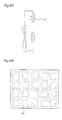
- two or more LED elements 101 may be provided in a common case 105, as shown in FIGS. 5A and 5B .
- LED elements of the same type alone may be used as the LED elements 101, or alternatively, LEDs of different types, mixed together, may be used.
- type used herein refers to classifications according to a wavelength range of light that can be emit, a peak wavelength, a light emission intensity, an element size, etc.
- FIGS. 6A and 6B a configuration as shown in FIGS. 6A and 6B may be used, so as to further increase the light emitting element integration degree.
- the LED elements 101 are arranged two-dimensionally on a light emitting face.
- adjacent ones of the LED elements 101 are formed in layers different from each other.
- LED elements other than the reflection-type LED elements, or an infrared light source other than LED elements, may be used as the infrared light source.
- another wavelength cut filter 103 is also provided on an emission side of the LED elements 101, in the configuration shown in FIGS. 6A and 6B as well.
- the LED elements 101 shown in FIGS. 2A and 2B , as well as FIGS. 5Aand 5B are elements of a type that is called "bullet-shaped type".
- the type used for the infrared light source is not limited to this type, but the reflection-type LED elements 101 shown in FIGS. 6A and 6B , or an infrared light source other than the LED elements may be used.
- infrared LEDs are mainly used in the cases described above, the configuration is not limited to this.
- Another light source for example, a xenon lamp, or a laser, can be used.
- the infrared ray emitting unit 204 is located at a position corresponding to the central portion of the image display region of the screen 203, but the present invention is not limited to this configuration.
- the infrared ray emitting unit 204 may be located at a position other than the central portion of the screen 203, for example, at a corner or at an end. Further, the infrared ray emitting unit 204 may be placed, not in the vicinity of the back face of the screen 203, but at a position of a certain distance from the back face of the screen 203.
- infrared light may be guided to the screen 203 via an optical fiber 306 from an infrared ray source 301 located at a distance from the screen 203.
Landscapes
- Engineering & Computer Science (AREA)
- Multimedia (AREA)
- Signal Processing (AREA)
- Physics & Mathematics (AREA)
- General Physics & Mathematics (AREA)
- Computer Security & Cryptography (AREA)
- Projection Apparatus (AREA)
- Overhead Projectors And Projection Screens (AREA)
- Transforming Electric Information Into Light Information (AREA)
- Studio Devices (AREA)
Applications Claiming Priority (2)
| Application Number | Priority Date | Filing Date | Title |
|---|---|---|---|
| JP2010041338A JP2011180172A (ja) | 2010-02-26 | 2010-02-26 | 撮像防止装置、撮像防止方法および映像表示システム |
| PCT/JP2011/054265 WO2011105546A1 (ja) | 2010-02-26 | 2011-02-25 | 撮像防止装置、撮像防止方法および映像表示システム |
Publications (1)
| Publication Number | Publication Date |
|---|---|
| EP2541320A1 true EP2541320A1 (en) | 2013-01-02 |
Family
ID=44506943
Family Applications (1)
| Application Number | Title | Priority Date | Filing Date |
|---|---|---|---|
| EP11747502A Withdrawn EP2541320A1 (en) | 2010-02-26 | 2011-02-25 | Imaging prevention device, imaging prevention method and image display system |
Country Status (4)
| Country | Link |
|---|---|
| US (1) | US20120315018A1 (https=) |
| EP (1) | EP2541320A1 (https=) |
| JP (1) | JP2011180172A (https=) |
| WO (1) | WO2011105546A1 (https=) |
Cited By (2)
| Publication number | Priority date | Publication date | Assignee | Title |
|---|---|---|---|---|
| CN105786165A (zh) * | 2014-12-24 | 2016-07-20 | 联想(北京)有限公司 | 一种信息处理方法和电子设备 |
| DE102015212776A1 (de) * | 2015-07-08 | 2017-01-12 | Siemens Aktiengesellschaft | Sichere Kommunikation |
Families Citing this family (7)
| Publication number | Priority date | Publication date | Assignee | Title |
|---|---|---|---|---|
| WO2011002059A1 (ja) * | 2009-07-03 | 2011-01-06 | シャープ株式会社 | 映像表示装置、映像表示方法、映像表示スクリーン、及び液晶表示装置 |
| US8780161B2 (en) * | 2011-03-01 | 2014-07-15 | Hewlett-Packard Development Company, L.P. | System and method for modifying images |
| US9438871B2 (en) | 2012-12-26 | 2016-09-06 | Citizen Holdings Co., Ltd. | Laser projection apparatus with bundled fibers |
| JP5880506B2 (ja) * | 2013-09-19 | 2016-03-09 | 富士ゼロックス株式会社 | 処理装置 |
| CN104767924B (zh) * | 2015-04-28 | 2018-03-30 | 西安科技大学 | 一种矿用高清视频采集系统及方法 |
| JP7347205B2 (ja) * | 2019-12-26 | 2023-09-20 | セイコーエプソン株式会社 | 投写システムの制御方法、投写システム及び制御プログラム |
| CN114067441B (zh) * | 2022-01-14 | 2022-04-08 | 合肥高维数据技术有限公司 | 摄录行为检测方法及系统 |
Family Cites Families (17)
| Publication number | Priority date | Publication date | Assignee | Title |
|---|---|---|---|---|
| JPH0429472Y2 (https=) * | 1987-07-06 | 1992-07-16 | ||
| DE3884385T2 (de) * | 1987-12-22 | 1994-05-05 | Takenaka Eng Co Ltd | Infrarotdetektor. |
| US6018374A (en) * | 1996-06-25 | 2000-01-25 | Macrovision Corporation | Method and system for preventing the off screen copying of a video or film presentation |
| US6473106B2 (en) * | 1999-12-02 | 2002-10-29 | Canon Kabushiki Kaisha | LED head, image forming apparatus, and method of measuring amount of light from LED array |
| US6742901B2 (en) * | 2001-05-16 | 2004-06-01 | Sony Corporation | Imaging prevention method and system |
| JP3468228B2 (ja) * | 2001-05-16 | 2003-11-17 | ソニー株式会社 | 撮像妨害方法及びシステム |
| US6868229B2 (en) * | 2001-09-20 | 2005-03-15 | Intel Corporation | Interfering with illicit recording activity by emitting non-visible radiation |
| WO2004112207A1 (en) * | 2003-06-12 | 2004-12-23 | Southampton Photonics Ltd. | Optical apparatus, comprising a brightness converter, for providing optical radiation |
| US20070103552A1 (en) * | 2005-11-10 | 2007-05-10 | Georgia Tech Research Corporation | Systems and methods for disabling recording features of cameras |
| WO2009114433A2 (en) * | 2008-03-08 | 2009-09-17 | Redwood Scientific, Inc. | Device and method for quantifying a surface's cleanliness |
| US20090268942A1 (en) * | 2008-04-23 | 2009-10-29 | Price John D | Methods and apparatus for detection of motion picture piracy for piracy prevention |
| JP5161655B2 (ja) * | 2008-05-22 | 2013-03-13 | 日本放送協会 | 盗撮防止装置 |
| US20100008501A1 (en) * | 2008-07-10 | 2010-01-14 | Ushio Denki Kabushiki Kaisha | Illegal recording prevention apparatus |
| JP2010231748A (ja) * | 2009-03-26 | 2010-10-14 | Isafe:Kk | 盗撮防止装置 |
| JP2010020263A (ja) | 2008-07-10 | 2010-01-28 | Isafe:Kk | 盗撮防止装置 |
| WO2011002059A1 (ja) * | 2009-07-03 | 2011-01-06 | シャープ株式会社 | 映像表示装置、映像表示方法、映像表示スクリーン、及び液晶表示装置 |
| JP5475393B2 (ja) * | 2009-10-20 | 2014-04-16 | キヤノン株式会社 | 撮像システムおよび補正方法 |
-
2010
- 2010-02-26 JP JP2010041338A patent/JP2011180172A/ja active Pending
-
2011
- 2011-02-25 US US13/580,235 patent/US20120315018A1/en not_active Abandoned
- 2011-02-25 WO PCT/JP2011/054265 patent/WO2011105546A1/ja not_active Ceased
- 2011-02-25 EP EP11747502A patent/EP2541320A1/en not_active Withdrawn
Non-Patent Citations (1)
| Title |
|---|
| See references of WO2011105546A1 * |
Cited By (2)
| Publication number | Priority date | Publication date | Assignee | Title |
|---|---|---|---|---|
| CN105786165A (zh) * | 2014-12-24 | 2016-07-20 | 联想(北京)有限公司 | 一种信息处理方法和电子设备 |
| DE102015212776A1 (de) * | 2015-07-08 | 2017-01-12 | Siemens Aktiengesellschaft | Sichere Kommunikation |
Also Published As
| Publication number | Publication date |
|---|---|
| JP2011180172A (ja) | 2011-09-15 |
| US20120315018A1 (en) | 2012-12-13 |
| WO2011105546A1 (ja) | 2011-09-01 |
Similar Documents
| Publication | Publication Date | Title |
|---|---|---|
| EP2541320A1 (en) | Imaging prevention device, imaging prevention method and image display system | |
| EP2059039A1 (en) | Global anticamcorder projection system and method | |
| JP6431861B2 (ja) | 風景の背景と前景とを区別する方法、及び風景の画像において背景を置き換える方法 | |
| US7747015B2 (en) | Techniques of imperceptibly altering the spectrum of a displayed image in a manner that discourages copying | |
| WO2011002059A1 (ja) | 映像表示装置、映像表示方法、映像表示スクリーン、及び液晶表示装置 | |
| JP3518528B2 (ja) | 撮像妨害方法及びシステム | |
| US20120314085A1 (en) | Video image display screen, video image display system, and method for detecting camera used in illegal camcording | |
| US20100008501A1 (en) | Illegal recording prevention apparatus | |
| JP2011180172A5 (https=) | ||
| JP5161741B2 (ja) | 投影スクリーン | |
| JP5373662B2 (ja) | 映像表示装置 | |
| WO2012070273A1 (ja) | 画像表示装置およびそれに用いられる盗撮防止装置 | |
| JP2010231748A (ja) | 盗撮防止装置 | |
| Yamada et al. | Preventing re-recording based on difference between sensory perceptions of humans and devices | |
| US20100134630A1 (en) | Frequency and spectral domain solutions for prevention of video recording | |
| Yamada et al. | IR hiding: a method to prevent video re-shooting by exploiting differences between human perceptions and recording device characteristics | |
| Echizen et al. | IR hiding: method for preventing illegal recording of videos based on differences in sensory perception between humans and devices | |
| US20100103331A1 (en) | Frequency and spectral domain solutions for prevention of video recording | |
| Yamada et al. | Preventing unauthorized copying of displayed information by utilizing differences in spectral sensitivity between humans and imaging devices | |
| CA2760686A1 (en) | Movie piracy copyright protection | |
| WO2012117906A1 (ja) | 映像表示スクリーン、映像表示システム、および撮影装置検出方法 | |
| GB2417848A (en) | A method and apparatus for impairing the formation of digital images | |
| WO1999066717A1 (de) | Übertragungsvorrichtung zur verdeckten übertragung von bildinhalten |
Legal Events
| Date | Code | Title | Description |
|---|---|---|---|
| PUAI | Public reference made under article 153(3) epc to a published international application that has entered the european phase |
Free format text: ORIGINAL CODE: 0009012 |
|
| 17P | Request for examination filed |
Effective date: 20120820 |
|
| AK | Designated contracting states |
Kind code of ref document: A1 Designated state(s): AL AT BE BG CH CY CZ DE DK EE ES FI FR GB GR HR HU IE IS IT LI LT LU LV MC MK MT NL NO PL PT RO RS SE SI SK SM TR |
|
| STAA | Information on the status of an ep patent application or granted ep patent |
Free format text: STATUS: THE APPLICATION HAS BEEN WITHDRAWN |
|
| DAX | Request for extension of the european patent (deleted) | ||
| 18W | Application withdrawn |
Effective date: 20130430 |