EP2541233A1 - Automatic analysis device - Google Patents
Automatic analysis device Download PDFInfo
- Publication number
- EP2541233A1 EP2541233A1 EP11747424A EP11747424A EP2541233A1 EP 2541233 A1 EP2541233 A1 EP 2541233A1 EP 11747424 A EP11747424 A EP 11747424A EP 11747424 A EP11747424 A EP 11747424A EP 2541233 A1 EP2541233 A1 EP 2541233A1
- Authority
- EP
- European Patent Office
- Prior art keywords
- light
- photoreceiver
- process data
- cell
- reaction process
- Prior art date
- Legal status (The legal status is an assumption and is not a legal conclusion. Google has not performed a legal analysis and makes no representation as to the accuracy of the status listed.)
- Granted
Links
Images


Classifications
-
- G—PHYSICS
- G01—MEASURING; TESTING
- G01N—INVESTIGATING OR ANALYSING MATERIALS BY DETERMINING THEIR CHEMICAL OR PHYSICAL PROPERTIES
- G01N21/00—Investigating or analysing materials by the use of optical means, i.e. using sub-millimetre waves, infrared, visible or ultraviolet light
- G01N21/17—Systems in which incident light is modified in accordance with the properties of the material investigated
- G01N21/47—Scattering, i.e. diffuse reflection
- G01N21/49—Scattering, i.e. diffuse reflection within a body or fluid
- G01N21/51—Scattering, i.e. diffuse reflection within a body or fluid inside a container, e.g. in an ampoule
-
- G—PHYSICS
- G01—MEASURING; TESTING
- G01N—INVESTIGATING OR ANALYSING MATERIALS BY DETERMINING THEIR CHEMICAL OR PHYSICAL PROPERTIES
- G01N21/00—Investigating or analysing materials by the use of optical means, i.e. using sub-millimetre waves, infrared, visible or ultraviolet light
- G01N21/17—Systems in which incident light is modified in accordance with the properties of the material investigated
- G01N21/47—Scattering, i.e. diffuse reflection
- G01N21/49—Scattering, i.e. diffuse reflection within a body or fluid
- G01N21/53—Scattering, i.e. diffuse reflection within a body or fluid within a flowing fluid, e.g. smoke
- G01N21/532—Scattering, i.e. diffuse reflection within a body or fluid within a flowing fluid, e.g. smoke with measurement of scattering and transmission
-
- G—PHYSICS
- G01—MEASURING; TESTING
- G01N—INVESTIGATING OR ANALYSING MATERIALS BY DETERMINING THEIR CHEMICAL OR PHYSICAL PROPERTIES
- G01N21/00—Investigating or analysing materials by the use of optical means, i.e. using sub-millimetre waves, infrared, visible or ultraviolet light
- G01N21/75—Systems in which material is subjected to a chemical reaction, the progress or the result of the reaction being investigated
- G01N21/77—Systems in which material is subjected to a chemical reaction, the progress or the result of the reaction being investigated by observing the effect on a chemical indicator
- G01N21/82—Systems in which material is subjected to a chemical reaction, the progress or the result of the reaction being investigated by observing the effect on a chemical indicator producing a precipitate or turbidity
-
- G—PHYSICS
- G01—MEASURING; TESTING
- G01N—INVESTIGATING OR ANALYSING MATERIALS BY DETERMINING THEIR CHEMICAL OR PHYSICAL PROPERTIES
- G01N35/00—Automatic analysis not limited to methods or materials provided for in any single one of groups G01N1/00 - G01N33/00; Handling materials therefor
- G01N35/02—Automatic analysis not limited to methods or materials provided for in any single one of groups G01N1/00 - G01N33/00; Handling materials therefor using a plurality of sample containers moved by a conveyor system past one or more treatment or analysis stations
- G01N35/025—Automatic analysis not limited to methods or materials provided for in any single one of groups G01N1/00 - G01N33/00; Handling materials therefor using a plurality of sample containers moved by a conveyor system past one or more treatment or analysis stations having a carousel or turntable for reaction cells or cuvettes
-
- G—PHYSICS
- G01—MEASURING; TESTING
- G01N—INVESTIGATING OR ANALYSING MATERIALS BY DETERMINING THEIR CHEMICAL OR PHYSICAL PROPERTIES
- G01N21/00—Investigating or analysing materials by the use of optical means, i.e. using sub-millimetre waves, infrared, visible or ultraviolet light
- G01N21/17—Systems in which incident light is modified in accordance with the properties of the material investigated
- G01N21/47—Scattering, i.e. diffuse reflection
- G01N2021/4704—Angular selective
- G01N2021/4711—Multiangle measurement
-
- G—PHYSICS
- G01—MEASURING; TESTING
- G01N—INVESTIGATING OR ANALYSING MATERIALS BY DETERMINING THEIR CHEMICAL OR PHYSICAL PROPERTIES
- G01N21/00—Investigating or analysing materials by the use of optical means, i.e. using sub-millimetre waves, infrared, visible or ultraviolet light
- G01N21/75—Systems in which material is subjected to a chemical reaction, the progress or the result of the reaction being investigated
- G01N21/77—Systems in which material is subjected to a chemical reaction, the progress or the result of the reaction being investigated by observing the effect on a chemical indicator
- G01N21/82—Systems in which material is subjected to a chemical reaction, the progress or the result of the reaction being investigated by observing the effect on a chemical indicator producing a precipitate or turbidity
- G01N2021/825—Agglutination
-
- Y—GENERAL TAGGING OF NEW TECHNOLOGICAL DEVELOPMENTS; GENERAL TAGGING OF CROSS-SECTIONAL TECHNOLOGIES SPANNING OVER SEVERAL SECTIONS OF THE IPC; TECHNICAL SUBJECTS COVERED BY FORMER USPC CROSS-REFERENCE ART COLLECTIONS [XRACs] AND DIGESTS
- Y10—TECHNICAL SUBJECTS COVERED BY FORMER USPC
- Y10T—TECHNICAL SUBJECTS COVERED BY FORMER US CLASSIFICATION
- Y10T436/00—Chemistry: analytical and immunological testing
- Y10T436/11—Automated chemical analysis
- Y10T436/113332—Automated chemical analysis with conveyance of sample along a test line in a container or rack
Definitions
- the present invention relates to an auto analyzer that analyzes component amounts contained in a sample, e.g., an auto analyzer that analyzes component amounts contained in blood or urine.
- reaction process data a data series of changes in the amount of light at given points in time
- Auto analyzers measure, as reactions of reaction solutions, two broad categories of reactions, namely color reactions between a substrate and an enzyme, and agglutination reactions between an antigen and an antibody.
- the former relate to biochemical assays which may be used to test for LDH (lactate dehydrogenase), ALP (alkaline phosphatase), AST (aspartate oxoglutarate aminotransferase), etc.
- the latter relate to immunoassays which may be used to test for CRP (C-reactive protein), IgG (immunoglobulin G), RF (rheumatoid factor), etc. Some substances measured by the latter immunoassays are found in blood in low concentrations, and thus require high sensitivity.
- a reagent in which the surfaces of latex particles are sensitized (bound) with antibodies is used, and, as a component contained in the sample is recognized and agglutination is caused, the reaction solution is irradiated with light to measure the amount of light transmitted without being scattered by the latex clumps, thereby determining the amount of the component contained in the sample.
- Patent Literature 2 a system in which transmitted light and scattering light are separated using a diaphragm, and absorbance and scattering light are simultaneously measured
- Patent Literature 3 a feature whereby precision on the high-concentration side is enhanced by measuring reflected scattering light caused by large clumps that are formed as an agglutination reaction progresses
- Patent Literature 4 a method in which integrating spheres are placed in front of and behind a reaction container, the respective average light amounts of forward scattering light and back scattering light are measured, and changes in turbidity caused by cell misalignment are corrected
- Patent Literature 5 a method that provides for easier device size reduction and device adjustment by disposing a fluorescence/scattering light measurement detection system in the same plane as the cell rotation direction
- Patent Literature 2 may enable scattering light and transmitted light to be measured simultaneously, there is no disclosure regarding any data processing method. Although scattering light is obtained in Patent Literature 3, this is done to improve precision on the high-concentration side, and it is ineffective for enhancing sensitivity for low concentrations. Patent Literature 4 averages scattering light with the integrating spheres, which does not result in enhanced sensitivity. Further, the system performs measurement while the cells are stationary. While Patent Literature 5 relates to a turbidity measuring method in which turbidity is calculated based on the ratio between scattering light intensity and transmitted light intensity, there is no disclosure of a specific processing method.
- the reaction process data received at one of the photoreceivers is corrected with estimated noise estimated from the reaction process data received at the other photoreceiver, thereby reducing noise.
- the photoreceiver closer to the optical axis is taken to be a main angle photoreceiver
- the photoreceiver farther from the optical axis is taken to be a sub-angle photoreceiver
- noise is reduced by subtracting from the reaction process data of the main angle photoreceiver the estimated noise estimated from the reaction process data of the sub-angle photoreceiver.
- Both the main angle photoreceiver and the sub-angle photoreceiver are, in practice, disposed at positions for receiving scattering light whose scattering angles are greater than 0° but equal to or less than 35°.
- reaction process data A(t, y at ) of the main angle photoreceiver is approximated with fitting function f a (t)
- reaction process data B(t, y bt ) of the sub-angle photoreceiver is approximated with fitting function f b (t).
- Sensitivity ratio ⁇ between the main angle photoreceiver and the sub-angle photoreceiver is assumed to be the ratio of gradients f a ' (t) to f b ' (t) of f a (t) and f b (t), respectively, indicated below.
- n(t) at reaction time t is defined as follows in terms of sensitivity ratio ⁇ and residual error r b (t).
- n t ⁇ ⁇ r b t
- Noise corrected reaction process data C(t, y ct ) is obtained using data value y ct , which is calculated by subtracting estimated noise n(t) from reaction process data value y at of the main angle photoreceiver.
- y ct y at - n t
- a component amount in the sample is determined using this noise corrected reaction process data.
- Fitting functions f a (t) and f b (t) above may be linear functions, or other functions may be used.
- signals may be amplified, which is advantageous for enhancing sensitivity.
- the photoreceiver that receives scattering light is, in practice, disposed at a position for receiving scattering light whose scattering angle is greater than 0° but equal to or less than 35°.
- a description is provided taking as an example a case where a main angle photoreceiver is disposed at a scattering angle of 20° and a sub-angle photoreceiver at a scattering angle of 30°.
- Fig. 1 is a schematic view showing an overall configuration example of an auto analyzer according to the present invention.
- This auto analyzer is equipped with a scattering light measuring unit for enhancing sensitivity.
- the auto analyzer mainly comprises: three types of disks, namely a sample disk 3, a reagent disk 6, and a cell disk 9; dispensing mechanisms for moving samples and reagents among these disks; a control unit that controls the above; a measurement unit; an analysis unit that processes measured data; a data storage unit that stores control data, measurement data, and analysis data; and an input unit and an output unit for inputting/outputting data to/from the data storage unit.
- a plurality of sample cups 2 each containing a sample 1 are disposed along the circumference of the sample disk 3.
- a plurality of reagent bottles 5 each containing a reagent 4 are disposed in the reagent disk 6.
- a plurality of cells 8 in which the sample 1 and the reagent 4 are to be mixed to obtain a reaction solution 7 are disposed along the circumference of the cell disk 9.
- a sample dispensing mechanism 10 moves a given amount of the sample 1 from the sample cups 2 to the cells 8.
- a reagent dispensing mechanism 11 moves a given amount of the reagent 4 from the reagent bottles 5 to the cells 8.
- a stirring unit 12 stirs and mixes the sample 1 and the reagent 4 within the cells 8.
- a washing unit 14 discharges the reaction solution 7 from the cells 8 whose analyses have been completed and washes them. With respect to the washed cells 8, the next sample 1 is dispensed from the sample dispensing mechanism 10 again, and a new reagent 4 is dispensed from the reagent dispensing mechanism 11, and they are thus used for another reaction.
- the cells 8 are immersed in a constant temperature fluid 17 in a constant temperature bath whose temperature and flow rate are controlled, and the cells 8, as well as the reaction solution 7 therein, are moved while being kept at a constant temperature. Water is used for the constant temperature fluid 17, and the temperature and flow rate of the constant temperature fluid are controlled at a constant temperature fluid control unit. The temperature is regulated at the reaction temperature, namely 37°C ⁇ 0.1°C.
- a transmitted light measuring unit 13 and a scattering light measuring unit 31 are each provided at some part along the circumference of the cell disk.
- the transmitted light measuring unit 13 and the scattering light measuring unit 31 each irradiate the reaction solution in the cells with light from a light source and measure light that has interacted with the reaction solution.
- the transmitted light measuring unit 13 irradiates the moving cells with light from a halogen lamp light source, and, after dispersion with a diffraction grating, receives the transmitted light with a photodiode array in which photodiodes are arranged in an array.
- FIG. 2 A schematic of the scattering light measuring unit 31 is shown in Fig. 2 .
- the moving cells 8 are irradiated with irradiating light 36 from an LED light source 35, and transmitted light 37 is received with a transmitted light photoreceiver 32.
- main scattering light 34a and sub-scattering light 34b are measured with scattering light photoreceivers 33a and 33b, respectively.
- the main scattering light 34a and the sub-scattering light 34b are removed from the optical axis of the transmitted light 37 by scattering light reception angles ⁇ 1 and ⁇ 2 respectively.
- ⁇ 1and ⁇ 2 were 20° and 30°, respectively.
- LED light source 35 L660-02V with an irradiating light wavelength of 660 nm, manufactured by Epitex, was used. Although, in this case, scattering light photoreceivers were disposed at 20°- and 30°-positions, optical systems, such as fibers and lenses, may instead be disposed at the same positions to guide light to scattering light photoreceivers disposed elsewhere. Although an LED was used for the light source 35, it may also be a laser, a xenon lamp, or a halogen lamp.
- the analysis of the component amounts in the sample 1 is performed in the following steps. First, a given amount of the sample 1 in the sample cups 2 is dispensed into the cells 8 by the sample dispensing mechanism 10. Next, a given amount of the reagent 4 in the reagent bottles 5 is dispensed into the cells 8 by the reagent dispensing mechanism 11. When thus dispensing, the sample disk 3, the reagent disk 6 and the cell disk 9 are driven to rotate by their respective drive units under the control of the control unit, and the sample cups 2, the reagent bottles 5, and the cells 8 are moved in time with the dispensing mechanisms. Next, the sample 1 and the reagent 4 in the cells 8 are stirred by the stirring unit 12, and the reaction solution 7 is obtained. Fig.
- the transmitted light and scattering light from the reaction solution 7 are measured each time they pass through measurement positions of the transmitted light measuring unit 13 and the scattering light measuring unit 31 while the cell disk 9 is rotating, and are sequentially accumulated as reaction process data in the data storage unit via the measurement unit. After measuring light for approximately 10 minutes, the insides of the cells 8 are washed by the washing mechanism 14, and the next analysis is performed.
- reaction process data for the reaction solution 7 with a given time interval are stored in the data storage unit.
- component amounts are analyzed at the analysis unit based on calibration curve data per test item.
- the data required for the control and analyses of the various units is inputted to the data storage unit from the input unit.
- the calibration curve data is held in the data storage unit.
- Various data, results, and alarms are outputted via display, etc., by the output unit.
- a CRP reagent (nanopia CRP, manufactured by Sekisui Medical Co., Ltd.) was used for the latex item, and CRP Calibrator (manufactured by Sekisui Medical Co., Ltd.) 0.005 mg/dL concentration was used for the sample. After dispensing and stirring, the amount of light of the reaction solution was measured at the scattering light measuring unit 31 every five seconds for five minutes. Component amounts were determined from the measured reaction process data.
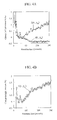
- Fig. 3A is a chart showing reaction process data A(t, y at ) by the main angle photoreceiver 33a disposed at a scattering angle of 20° and its fitting function f a (t).
- Fig. 3B is a chart showing reaction process data B(t, y bt ) by the sub-angle photoreceiver 33b disposed at a scattering angle of 30° and its fitting function f b (t).
- Fig. 3A is a chart showing reaction process data A(t, y at ) by the main angle photoreceiver 33a disposed at a scattering angle of 20° and its fitting function f a (t).
- Fig. 3B is a chart showing reaction process data B(t, y bt ) by the sub-angle photoreceiver 33b disposed at a scattering angle of 30° and its fitting function f b (t).
- reaction process data B(t, y bt ) residual error r b (t)
- noise corrected reaction process data C(t, y ct ) after data processing is shown in Fig. 3C .
- the vertical axis of the reaction process data represents the change in light amount (%), which is the proportion of the difference between light amounts at a given time and 45 seconds after the introduction of the latex reagent, where the light amount after 45 seconds is taken to be 100%.
- the horizontal axis represents the time elapsed since the introduction of the latex reagent.
- Noise corrected reaction process data C(t, y ct ) Data obtained by subtracting estimated noise n(t), which is estimated based on reaction process data B(t, y bt ) of the sub-angle photoreceiver, is shown in Fig. 3C as noise corrected reaction process data C(t, y ct ) that has undergone data processing.
- data value y ct of noise corrected reaction process data C(t, y ct ) after data processing is given by the following.
- a method is described where a first photoreceiver is disposed at a position for receiving scattering light with a scattering angle of 20°, a second photoreceiver is disposed at a transmitted light receiving position (0°-scattering angle), and signals are amplified using reaction process data of these two photoreceivers when transmitted light is received.
- the device configuration is otherwise similar to that of Embodiment 1.
- the position of the first photoreceiver is not limited to a position for receiving scattering light with a scattering angle of 20°. It need only be disposed generally at a position for receiving scattering light whose scattering angle is greater than 0° but equal to or less than 35°, depending on the component being analyzed or the reaction type.
- Reaction process data A(t, y at ) of the first photoreceiver and reaction process data D(t, y dt ) of the second photoreceiver are shown in Fig. 4A .
- Data value yet of transmitted light corrected reaction process data E(t, yet) is calculated based on y at and y dt as in the following equation.
Landscapes
- Chemical & Material Sciences (AREA)
- Physics & Mathematics (AREA)
- General Physics & Mathematics (AREA)
- Immunology (AREA)
- Life Sciences & Earth Sciences (AREA)
- Analytical Chemistry (AREA)
- Biochemistry (AREA)
- General Health & Medical Sciences (AREA)
- Pathology (AREA)
- Health & Medical Sciences (AREA)
- Chemical Kinetics & Catalysis (AREA)
- Engineering & Computer Science (AREA)
- Plasma & Fusion (AREA)
- Automatic Analysis And Handling Materials Therefor (AREA)
- Investigating Or Analysing Materials By Optical Means (AREA)
- Investigating Or Analysing Materials By The Use Of Chemical Reactions (AREA)
Abstract
Description
- The present invention relates to an auto analyzer that analyzes component amounts contained in a sample, e.g., an auto analyzer that analyzes component amounts contained in blood or urine.
- As auto analyzers that analyze component amounts contained in a sample, devices that irradiate a sample, or a reaction solution in which a sample and a reagent are mixed, with light from a light source, measure the amount of transmitted light with respect to a single wavelength or a plurality of wavelengths obtained as a result to calculate the absorbance, and determine component amounts based on the relationship between absorbance and density in accordance with the Lambert-Beer law are used widely (e.g., Patent Literature 1). In such devices, numerous cells holding a reaction solution are arranged along the circumference of a cell disk that alternates between rotating and being stationary, and, while the cell disk is rotating, a data series of changes in the amount of light at given points in time (reaction process data) is measured as changes in the amount of received light over time for approximately ten minutes at regular time intervals by a transmitted light measuring unit disposed at a predetermined position.
- Auto analyzers measure, as reactions of reaction solutions, two broad categories of reactions, namely color reactions between a substrate and an enzyme, and agglutination reactions between an antigen and an antibody. The former relate to biochemical assays which may be used to test for LDH (lactate dehydrogenase), ALP (alkaline phosphatase), AST (aspartate oxoglutarate aminotransferase), etc. The latter relate to immunoassays which may be used to test for CRP (C-reactive protein), IgG (immunoglobulin G), RF (rheumatoid factor), etc. Some substances measured by the latter immunoassays are found in blood in low concentrations, and thus require high sensitivity. For such substances, a reagent in which the surfaces of latex particles are sensitized (bound) with antibodies is used, and, as a component contained in the sample is recognized and agglutination is caused, the reaction solution is irradiated with light to measure the amount of light transmitted without being scattered by the latex clumps, thereby determining the amount of the component contained in the sample.
- With respect to the above, there have been attempts to enhance sensitivity by measuring the amount of scattering light, instead of measuring the amount of transmitted light as is done in ordinary analyses. By way of example, there have been disclosed: a system in which transmitted light and scattering light are separated using a diaphragm, and absorbance and scattering light are simultaneously measured (Patent Literature 2); a feature whereby precision on the high-concentration side is enhanced by measuring reflected scattering light caused by large clumps that are formed as an agglutination reaction progresses (Patent Literature 3); a method in which integrating spheres are placed in front of and behind a reaction container, the respective average light amounts of forward scattering light and back scattering light are measured, and changes in turbidity caused by cell misalignment are corrected (Patent Literature 4); a method that provides for easier device size reduction and device adjustment by disposing a fluorescence/scattering light measurement detection system in the same plane as the cell rotation direction (Patent Literature 5); a turbidity measuring method in which turbidity is calculated based on the ratio between scattering light intensity and transmitted light intensity with respect to particles flowing in a flow cell (Patent Literature 6); etc.
-
- Patent Literature 1:
US Patent No. 4,451,433 - Patent Literature 2:
JP 2000-307117 A - Patent Literature 3:
JP 2008-8794 A - Patent Literature 4:
JP 10-332582 A (1998 - Patent Literature 5:
JP 1-295134 A (1989 - Patent Literature 6:
JP 9-273987 A (1997 - With respect to photometers that utilize scattering light, no efforts have hitherto been made to enhance sensitivity through the processing of reaction process data. Although
Patent Literature 2 may enable scattering light and transmitted light to be measured simultaneously, there is no disclosure regarding any data processing method. Although scattering light is obtained inPatent Literature 3, this is done to improve precision on the high-concentration side, and it is ineffective for enhancing sensitivity for low concentrations.Patent Literature 4 averages scattering light with the integrating spheres, which does not result in enhanced sensitivity. Further, the system performs measurement while the cells are stationary. WhilePatent Literature 5 relates to a turbidity measuring method in which turbidity is calculated based on the ratio between scattering light intensity and transmitted light intensity, there is no disclosure of a specific processing method. - In order to enhance sensitivity, it is important that signals (changes in light amount) increase, and noise decrease, in the reaction process. In general, data processing methods that are effective with respect to noise vary depending on the main cause thereof. If random noise is the main cause, a process in which light amounts measured with a plurality of photoreceivers are averaged is effective, whereas if air bubbles, dirt, etc., are the main cause, a process in which the ratio or difference among light amounts measured with a plurality of photoreceivers is determined is effective.
- Since auto analyzers take measurements while cells are rotating, it becomes important to secure a light amount with which sufficient measurement precision may be maintained even in short periods of time. In scattering light measurement, since the latex clumps and the wavelength are on approximately the same order of size, it falls into the realm of Mie scattering, which is advantageous in terms of securing light amounts since the amount of scattering light is large in the forward direction. In order to measure forward light, only light that has traveled through a square transmitting surface of a cell is to be measured, and light must be received at an angle that prevents entry of light that has traveled through the bottom surface of the cell or the solution surface. To that end, it is preferable that scattering light at an angle of approximately 35° or less relative to the optical axis be received. In auto analyzers, the latter air bubbles, dirt, etc., often become causes of noise. In ordinary transmitted light measurement, influences of air bubbles and dirt are eliminated by determining the ratio or difference among light amounts of numerous wavelengths. However, in the case of scattering light measurement, it is speculated that it is advantageous to determine the light amount ratio or difference among numerous angles. However, there was a problem in that, when a plurality of photoreceivers are disposed in such a manner as to receive scattering light at angles of 35° or less relative to the optical axis, and the ratio or difference of reaction process data among these plurality of photoreceivers are obtained as new reaction process data, signals drop and sensitivity does not improve because there is little difference among the light amounts, or the changes in light amount, thereof. As such, there is demand for a data processing method that improves sensitivity by determining the ratio or difference among light amounts without causing signals to drop.
- In the present invention, in determining the ratio or difference between light amounts received by two scattering light photoreceivers disposed in the forward direction, the reaction process data received at one of the photoreceivers is corrected with estimated noise estimated from the reaction process data received at the other photoreceiver, thereby reducing noise. In particular, where, of the two scattering light photoreceivers, the photoreceiver closer to the optical axis is taken to be a main angle photoreceiver, and the photoreceiver farther from the optical axis is taken to be a sub-angle photoreceiver, noise is reduced by subtracting from the reaction process data of the main angle photoreceiver the estimated noise estimated from the reaction process data of the sub-angle photoreceiver. Both the main angle photoreceiver and the sub-angle photoreceiver are, in practice, disposed at positions for receiving scattering light whose scattering angles are greater than 0° but equal to or less than 35°.
- More specifically, reaction process data A(t, yat) of the main angle photoreceiver is approximated with fitting function fa(t), and reaction process data B(t, ybt) of the sub-angle photoreceiver is approximated with fitting function fb(t). Sensitivity ratio α between the main angle photoreceiver and the sub-angle photoreceiver is assumed to be the ratio of gradients fa' (t) to fb' (t) of fa(t) and fb(t), respectively, indicated below.
-

Residual error rb(t) as the difference between data value ybt and fitting function fb(t) of the sub-angle photoreceiver at reaction time t is defined as follows. -

Estimated noise n(t) at reaction time t is defined as follows in terms of sensitivity ratio α and residual error rb(t). -

-

A component amount in the sample is determined using this noise corrected reaction process data. Fitting functions fa(t) and fb(t) above may be linear functions, or other functions may be used. - Further, given how changes in light amount have opposite directionalities between transmitted light and scattering light (as the amount of scattering light increases, the amount of transmitted light decreases), a data processing method is indicated below for a case where the sub-angle photoreceiver is disposed in the 0°-direction, which coincides with the optical axis of the irradiating light. In this case, by determining the difference between the reaction process data of the scattering light photoreceiver and the reaction process data of the transmitted light photoreceiver, signals are amplified.
- Specifically, assuming that A(t, yat) is the reaction process data for scattering light, and that D(t, ydt) is the reaction process data for transmitted light, then transmitted light corrected reaction process data E (t, yet) is given by

Using this transmitted light corrected reaction process data, a component amount in the sample is determined. Thus, signals may be amplified, which is advantageous for enhancing sensitivity. In this case, too, the photoreceiver that receives scattering light is, in practice, disposed at a position for receiving scattering light whose scattering angle is greater than 0° but equal to or less than 35°. - With the present invention, through data processing using reaction process data of two scattering light photoreceivers, noise caused by air bubbles and dirt is reduced, thereby enabling high-sensitivity measurement.
-
-
Fig. 1 is a schematic view showing an overall configuration example of an auto analyzer according to the present invention. -
Fig. 2 is a schematic view of a scattering light measuring unit according to the present invention. -
Fig. 3A is a chart showing reaction process data by a main angle photoreceiver with respect toEmbodiment 1. -
Fig. 3B is a chart showing reaction process data by a sub-angle photoreceiver with respect toEmbodiment 1. -
Fig. 3C is a chart showing reaction process data after data processing with respect toEmbodiment 1. -
Fig. 4A is a chart showing reaction process data for each photoreceiver with respect toEmbodiment 2. -
Fig. 4B is a chart showing reaction process data after data processing with respect toEmbodiment 2. - Embodiments of the present invention are described below with reference to the drawings.
- A description is provided taking as an example a case where a main angle photoreceiver is disposed at a scattering angle of 20° and a sub-angle photoreceiver at a scattering angle of 30°.
-
Fig. 1 is a schematic view showing an overall configuration example of an auto analyzer according to the present invention. This auto analyzer is equipped with a scattering light measuring unit for enhancing sensitivity. The auto analyzer mainly comprises: three types of disks, namely asample disk 3, a reagent disk 6, and a cell disk 9; dispensing mechanisms for moving samples and reagents among these disks; a control unit that controls the above; a measurement unit; an analysis unit that processes measured data; a data storage unit that stores control data, measurement data, and analysis data; and an input unit and an output unit for inputting/outputting data to/from the data storage unit. - A plurality of
sample cups 2 each containing asample 1 are disposed along the circumference of thesample disk 3. A plurality ofreagent bottles 5 each containing areagent 4 are disposed in the reagent disk 6. A plurality ofcells 8 in which thesample 1 and thereagent 4 are to be mixed to obtain areaction solution 7 are disposed along the circumference of the cell disk 9. Asample dispensing mechanism 10 moves a given amount of thesample 1 from the sample cups 2 to thecells 8. Areagent dispensing mechanism 11 moves a given amount of thereagent 4 from thereagent bottles 5 to thecells 8. A stirringunit 12 stirs and mixes thesample 1 and thereagent 4 within thecells 8. Awashing unit 14 discharges thereaction solution 7 from thecells 8 whose analyses have been completed and washes them. With respect to the washedcells 8, thenext sample 1 is dispensed from thesample dispensing mechanism 10 again, and anew reagent 4 is dispensed from thereagent dispensing mechanism 11, and they are thus used for another reaction. Thecells 8 are immersed in aconstant temperature fluid 17 in a constant temperature bath whose temperature and flow rate are controlled, and thecells 8, as well as thereaction solution 7 therein, are moved while being kept at a constant temperature. Water is used for theconstant temperature fluid 17, and the temperature and flow rate of the constant temperature fluid are controlled at a constant temperature fluid control unit. The temperature is regulated at the reaction temperature, namely 37°C ± 0.1°C. A transmittedlight measuring unit 13 and a scatteringlight measuring unit 31 are each provided at some part along the circumference of the cell disk. The transmittedlight measuring unit 13 and the scatteringlight measuring unit 31 each irradiate the reaction solution in the cells with light from a light source and measure light that has interacted with the reaction solution. - The transmitted
light measuring unit 13 irradiates the moving cells with light from a halogen lamp light source, and, after dispersion with a diffraction grating, receives the transmitted light with a photodiode array in which photodiodes are arranged in an array. - A schematic of the scattering
light measuring unit 31 is shown inFig. 2 . The movingcells 8 are irradiated with irradiating light 36 from anLED light source 35, and transmitted light 37 is received with a transmitted light photoreceiver 32. In addition,main scattering light 34a and sub-scattering light 34b are measured with scatteringlight photoreceivers 33a and 33b, respectively. Themain scattering light 34a and the sub-scattering light 34b are removed from the optical axis of the transmitted light 37 by scattering light reception angles φ1 and φ2 respectively. In the present embodiment, φ1and φ2were 20° and 30°, respectively. For theLED light source 35, L660-02V with an irradiating light wavelength of 660 nm, manufactured by Epitex, was used. Although, in this case, scattering light photoreceivers were disposed at 20°- and 30°-positions, optical systems, such as fibers and lenses, may instead be disposed at the same positions to guide light to scattering light photoreceivers disposed elsewhere. Although an LED was used for thelight source 35, it may also be a laser, a xenon lamp, or a halogen lamp. - The analysis of the component amounts in the
sample 1 is performed in the following steps. First, a given amount of thesample 1 in the sample cups 2 is dispensed into thecells 8 by thesample dispensing mechanism 10. Next, a given amount of thereagent 4 in thereagent bottles 5 is dispensed into thecells 8 by thereagent dispensing mechanism 11. When thus dispensing, thesample disk 3, the reagent disk 6 and the cell disk 9 are driven to rotate by their respective drive units under the control of the control unit, and the sample cups 2, thereagent bottles 5, and thecells 8 are moved in time with the dispensing mechanisms. Next, thesample 1 and thereagent 4 in thecells 8 are stirred by the stirringunit 12, and thereaction solution 7 is obtained.Fig. 1 is a schematic view, and shows one each of the reagent disk and the reagent dispensing mechanism. However, there typically are two reagent disks, reagent dispensing mechanisms, and stirring units. The transmitted light and scattering light from thereaction solution 7 are measured each time they pass through measurement positions of the transmittedlight measuring unit 13 and the scatteringlight measuring unit 31 while the cell disk 9 is rotating, and are sequentially accumulated as reaction process data in the data storage unit via the measurement unit. After measuring light for approximately 10 minutes, the insides of thecells 8 are washed by thewashing mechanism 14, and the next analysis is performed. In the mean time, if necessary, anotherreagent 4 is additionally dispensed into thecells 8 by thereagent dispensing mechanism 11, stirring is carried out by the stirringunit 12, and further measurements are taken for a given period of time. Thus, reaction process data for thereaction solution 7 with a given time interval are stored in the data storage unit. With the accumulated reaction process data, component amounts are analyzed at the analysis unit based on calibration curve data per test item. The data required for the control and analyses of the various units is inputted to the data storage unit from the input unit. In addition, the calibration curve data is held in the data storage unit. Various data, results, and alarms are outputted via display, etc., by the output unit. - In the present embodiment, a CRP reagent (nanopia CRP, manufactured by Sekisui Medical Co., Ltd.) was used for the latex item, and CRP Calibrator (manufactured by Sekisui Medical Co., Ltd.) 0.005 mg/dL concentration was used for the sample. After dispensing and stirring, the amount of light of the reaction solution was measured at the scattering
light measuring unit 31 every five seconds for five minutes. Component amounts were determined from the measured reaction process data. - Reaction process data for a latex agglutination reaction measured by the two
photoreceivers 33a and 33b of the present embodiment are shown inFig. 3A andFig. 3B .Fig. 3A is a chart showing reaction process data A(t, yat) by the main angle photoreceiver 33a disposed at a scattering angle of 20° and its fitting function fa(t).Fig. 3B is a chart showing reaction process data B(t, ybt) by thesub-angle photoreceiver 33b disposed at a scattering angle of 30° and its fitting function fb(t). InFig. 3B , there is also shown residual error rb(t), which is the difference between reaction process data B(t, ybt) and its fitting function fb(t) at reaction time t. In addition, noise corrected reaction process data C(t, yct) after data processing is shown inFig. 3C . The vertical axis of the reaction process data represents the change in light amount (%), which is the proportion of the difference between light amounts at a given time and 45 seconds after the introduction of the latex reagent, where the light amount after 45 seconds is taken to be 100%. The horizontal axis represents the time elapsed since the introduction of the latex reagent. - Assuming fitting function fa(t) of the main angle photoreceiver's reaction process data A(t, yat) shown in
Fig. 3A is fa(t) = at + b, and that fitting function fb(t) of the sub-angle photoreceiver's reaction process data B(t, ybt) shown inFig. 3B is fb(t) = ct + d, sensitivity ratio α between the main angle photoreceiver and the sub-angle photoreceiver is given by α = a/c. Data obtained by subtracting estimated noise n(t), which is estimated based on reaction process data B(t, ybt) of the sub-angle photoreceiver, is shown inFig. 3C as noise corrected reaction process data C(t, yct) that has undergone data processing. For cases where, as in the present embodiment, fitting function fb(t) of B(t, ybt) is the linear equation fb(t) = ct + d, data value yct of noise corrected reaction process data C(t, yct) after data processing is given by the following. -

Thus, whereas the standard deviation among data values of the main angle photoreceiver's reaction process data shown inFig. 3A taken over a period of one minute was 0.1%, the standard deviation among data values taken over a period of one minute dropped to about seven tenths thereof, i.e., to 0.07%, for the data processed reaction process data shown inFig. 3C , thereby achieving enhanced sensitivity. - For the present embodiment, a method is described where a first photoreceiver is disposed at a position for receiving scattering light with a scattering angle of 20°, a second photoreceiver is disposed at a transmitted light receiving position (0°-scattering angle), and signals are amplified using reaction process data of these two photoreceivers when transmitted light is received. The device configuration is otherwise similar to that of
Embodiment 1. In addition, the position of the first photoreceiver is not limited to a position for receiving scattering light with a scattering angle of 20°. It need only be disposed generally at a position for receiving scattering light whose scattering angle is greater than 0° but equal to or less than 35°, depending on the component being analyzed or the reaction type. - Reaction process data A(t, yat) of the first photoreceiver and reaction process data D(t, ydt) of the second photoreceiver are shown in
Fig. 4A . Transmitted light corrected reaction process data E(t, yet) after data processing, which is obtained by determining the difference between reaction process data A(t, yat) and reaction process data D(t, ydt), is shown inFig. 4B . Data value yet of transmitted light corrected reaction process data E(t, yet) is calculated based on yat and ydt as in the following equation. -

-
- 1
- Sample
- 2
- Sample cup
- 3
- Sample disk
- 4
- Reagent
- 5
- Reagent bottle
- 6
- Reagent disk
- 7
- Reaction solution
- 8
- Cell
- 9
- Cell disk
- 10
- Sample dispensing mechanism
- 11
- Reagent dispensing mechanism
- 12
- Stirring unit
- 13
- Transmitted light measuring unit
- 14
- Washing unit
- 17
- Constant temperature fluid
- 31
- Scattering light measuring unit
- 32
- Transmitted light photoreceiver
- 33a, 33b
- Scattering light photoreceiver
- 34a, 34b
- Scattering light
- 35
- Light source
- 36
- Irradiating light
- 37
- Transmitted light
Claims (4)
- An auto analyzer comprising:a cell disk configured to hold a cell along its circumference, the cell containing a reaction solution in which a sample and a reagent are mixed, the cell disk being configured to alternate between rotating and being stationary; anda light measuring unit configured to irradiate the cell with irradiating light from a light source while the cell disk is rotating, and to measure light that has interacted with the reaction solution in the cell, whereinthe light measuring unit comprises:a first photoreceiver configured to receive scattering light that is closer to an optical axis of the irradiating light; anda second photoreceiver configured to receive scattering light that is further from the optical axis, whereinchanges in the amounts of light received by the photoreceivers over time are respectively measured as reaction process data, anda component amount in the reaction solution is determined using data obtained by subtracting noise from the reaction process data of the first photoreceiver, the noise being estimated by multiplying a difference between the reaction process data of the second photoreceiver and a fitting function for fitting the reaction process data of the second photoreceiver by a sensitivity ratio between the first photoreceiver and the second photoreceiver.
- The auto analyzer according to claim 1, wherein both the main angle photoreceiver and the sub-angle photoreceiver are disposed at positions for receiving scattering light whose scattering angles are greater than 0° but equal to or less than 35°C.
- The auto analyzer according to claim 1, wherein the fitting function comprises a linear function.
- An auto analyzer comprising:a cell disk configured to hold a cell along its circumference, the cell containing a reaction solution in which a sample and a reagent are mixed, the cell disk being configured to alternate between rotating and being stationary; anda light measuring unit configured to irradiate the cell with irradiating light from a light source while the cell disk is rotating, and to measure light that has interacted with the reaction solution in the cell, whereinthe light measuring unit comprises:a first photoreceiver configured to receive scattering light scattered at an angle of 35° or less relative to an optical axis of the irradiating light; anda second photoreceiver disposed along the optical axis of the irradiating light, whereinchanges in the amounts of light received by the photoreceivers over time are respectively measured as reaction process data, anda component amount in the reaction solution is determined using data obtained by subtracting the reaction process data of the second photoreceiver from the reaction process data of the first photoreceiver.
Applications Claiming Priority (2)
| Application Number | Priority Date | Filing Date | Title |
|---|---|---|---|
| JP2010039800A JP5379044B2 (en) | 2010-02-25 | 2010-02-25 | Automatic analyzer |
| PCT/JP2011/054067 WO2011105464A1 (en) | 2010-02-25 | 2011-02-24 | Automatic analysis device |
Publications (3)
| Publication Number | Publication Date |
|---|---|
| EP2541233A1 true EP2541233A1 (en) | 2013-01-02 |
| EP2541233A4 EP2541233A4 (en) | 2014-05-21 |
| EP2541233B1 EP2541233B1 (en) | 2017-11-01 |
Family
ID=44506865
Family Applications (1)
| Application Number | Title | Priority Date | Filing Date |
|---|---|---|---|
| EP11747424.7A Active EP2541233B1 (en) | 2010-02-25 | 2011-02-24 | Automatic analysis device |
Country Status (5)
| Country | Link |
|---|---|
| US (1) | US8858882B2 (en) |
| EP (1) | EP2541233B1 (en) |
| JP (1) | JP5379044B2 (en) |
| CN (1) | CN102753957B (en) |
| WO (1) | WO2011105464A1 (en) |
Cited By (2)
| Publication number | Priority date | Publication date | Assignee | Title |
|---|---|---|---|---|
| EP2818848A4 (en) * | 2012-02-24 | 2015-10-14 | Hitachi High Tech Corp | AUTOMATIC ANALYSIS DEVICE |
| EP2876433A4 (en) * | 2012-07-20 | 2016-07-13 | Hitachi High Tech Corp | AUTOMATIC ANALYSIS DEVICE AND METHOD |
Families Citing this family (13)
| Publication number | Priority date | Publication date | Assignee | Title |
|---|---|---|---|---|
| US8519358B2 (en) | 2008-02-05 | 2013-08-27 | Pocared Diagnostics Ltd. | System for conducting the identification of bacteria in biological samples |
| US10288632B2 (en) * | 2009-09-21 | 2019-05-14 | Pocared Diagnostics Ltd. | System for conducting the identification of bacteria in biological samples |
| JP5740264B2 (en) * | 2011-09-20 | 2015-06-24 | 株式会社日立ハイテクノロジーズ | Automatic analyzer and analysis method |
| JP5897323B2 (en) | 2011-12-26 | 2016-03-30 | 株式会社日立ハイテクノロジーズ | Automatic analyzer and measurement value abnormality detection method |
| JP6038464B2 (en) * | 2012-02-29 | 2016-12-07 | 東芝メディカルシステムズ株式会社 | Automatic analyzer |
| JP6138564B2 (en) * | 2013-04-18 | 2017-05-31 | 株式会社日立ハイテクノロジーズ | Automatic analyzer |
| JP6211806B2 (en) * | 2013-05-31 | 2017-10-11 | 株式会社日立ハイテクノロジーズ | Automatic analyzer |
| US9970948B2 (en) * | 2013-11-26 | 2018-05-15 | Hitachi High-Technologies Corporation | Automatic analyzer |
| CN106170702B (en) * | 2013-12-25 | 2018-09-21 | 株式会社日立高新技术 | Automatic analysis device and analysis method |
| JP6031552B2 (en) * | 2015-04-27 | 2016-11-24 | 株式会社日立ハイテクノロジーズ | Automatic analyzer and analysis method |
| EP3408648B1 (en) | 2016-01-28 | 2025-12-03 | Siemens Healthcare Diagnostics Inc. | Methods and apparatus for imaging a specimen container and/or specimen using multiple exposures |
| WO2021024535A1 (en) * | 2019-08-05 | 2021-02-11 | 株式会社日立ハイテク | Automatic analysis device |
| JP7837970B2 (en) * | 2021-06-25 | 2026-03-31 | 古野電気株式会社 | Photometric and analytical devices |
Family Cites Families (28)
| Publication number | Priority date | Publication date | Assignee | Title |
|---|---|---|---|---|
| US3619624A (en) * | 1969-01-10 | 1971-11-09 | Stanford Research Inst | Instrument for measurement of optical characteristics of water |
| GB1588862A (en) | 1978-05-11 | 1981-04-29 | Standard Telephones Cables Ltd | Measuring oil in water |
| US4420257A (en) * | 1980-02-14 | 1983-12-13 | Toyo Soda Manufacturing Co., Ltd. | Laser light scattering photometer |
| DE3005923A1 (en) * | 1980-02-16 | 1981-09-03 | Compur-Electronic GmbH, 8000 München | PHOTOMETRIC METHOD AND PHOTOMETRIC DEVICE FOR DETERMINING REACTION PROCESSES |
| JPS5782769A (en) | 1980-11-10 | 1982-05-24 | Hitachi Ltd | Automatic analyzing device |
| GB2105028B (en) | 1981-08-27 | 1985-04-03 | Itt Ind Ltd | Boiler feed contamination monitor |
| GB2166234B (en) * | 1984-10-27 | 1987-12-31 | Stc Plc | Detecting oil in water |
| JPS63205546A (en) * | 1987-02-20 | 1988-08-25 | Nippon Tectron Co Ltd | Automatic analysis instrument |
| JPH01295134A (en) | 1988-05-24 | 1989-11-28 | Toshiba Corp | Automatic chemical analyzer |
| JPH0545282A (en) * | 1991-08-09 | 1993-02-23 | Kurabo Ind Ltd | Automatic clinical analyzing system |
| JPH09273987A (en) | 1996-04-03 | 1997-10-21 | Fuji Electric Co Ltd | Method and apparatus for measuring particle size, number concentration or turbidity of fine particles in liquid |
| JPH10332582A (en) | 1997-05-28 | 1998-12-18 | Kyowa Medex Co Ltd | Measuring apparatus for turbidity |
| JP2000065744A (en) * | 1998-08-25 | 2000-03-03 | Hitachi Ltd | Automatic analyzer |
| JP2000230901A (en) * | 1999-02-09 | 2000-08-22 | Mitsubishi Chemicals Corp | Optical unit |
| DE19948587A1 (en) | 1999-10-08 | 2001-04-12 | Dade Behring Marburg Gmbh | Spectrophotometric and nephelometric detection unit |
| JP2002116145A (en) | 2000-10-06 | 2002-04-19 | Matsushita Electric Ind Co Ltd | Method and apparatus for measuring concentration of solution |
| JP2002250692A (en) * | 2001-02-22 | 2002-09-06 | Fellow Kogyo Co Ltd | Oil concentration measurement device and measurement method for oily water containing contaminants |
| US7636636B2 (en) * | 2001-10-12 | 2009-12-22 | Abbott Laboratories | Imaging microarrays |
| US20030087289A1 (en) * | 2001-10-12 | 2003-05-08 | Harry Zuzan | Image analysis of high-density synthetic DNA microarrays |
| JP2004264146A (en) * | 2003-02-28 | 2004-09-24 | Horiba Ltd | Optical device and analyzer having simple functions for preventing contamination and for correction |
| JP2005049109A (en) * | 2003-07-29 | 2005-02-24 | Toshiba Corp | Chemical analyzer |
| US20080218738A1 (en) * | 2004-04-10 | 2008-09-11 | Michael Trainer | Methods and apparatus for determining particle characteristics by measuring scattered light |
| CA2603389C (en) | 2005-05-13 | 2012-07-10 | Bio-Rad Laboratories, Inc. | Identifying statistically linear data |
| JP2007322324A (en) | 2006-06-02 | 2007-12-13 | Olympus Corp | Analyzer |
| JP2008008794A (en) | 2006-06-29 | 2008-01-17 | Olympus Corp | Analyzing device |
| JP4886785B2 (en) * | 2006-09-25 | 2012-02-29 | 興和株式会社 | Gelation measuring device and sample cell |
| JP5134862B2 (en) | 2007-05-16 | 2013-01-30 | 株式会社日立ハイテクノロジーズ | Analysis equipment |
| CN101482572B (en) * | 2008-01-11 | 2012-07-04 | 株式会社东芝 | Automatic analysis apparatus and automatic analysis method |
-
2010
- 2010-02-25 JP JP2010039800A patent/JP5379044B2/en active Active
-
2011
- 2011-02-24 CN CN201180009103.9A patent/CN102753957B/en active Active
- 2011-02-24 WO PCT/JP2011/054067 patent/WO2011105464A1/en not_active Ceased
- 2011-02-24 US US13/577,963 patent/US8858882B2/en active Active
- 2011-02-24 EP EP11747424.7A patent/EP2541233B1/en active Active
Cited By (4)
| Publication number | Priority date | Publication date | Assignee | Title |
|---|---|---|---|---|
| EP2818848A4 (en) * | 2012-02-24 | 2015-10-14 | Hitachi High Tech Corp | AUTOMATIC ANALYSIS DEVICE |
| US9400247B2 (en) | 2012-02-24 | 2016-07-26 | Hitachi High-Technologies Corporation | Automatic analyzer |
| EP2876433A4 (en) * | 2012-07-20 | 2016-07-13 | Hitachi High Tech Corp | AUTOMATIC ANALYSIS DEVICE AND METHOD |
| US9557264B2 (en) | 2012-07-20 | 2017-01-31 | Hitachi High-Technologies Corporation | Automatic analysis device, and automatic analysis method |
Also Published As
| Publication number | Publication date |
|---|---|
| US20120315190A1 (en) | 2012-12-13 |
| WO2011105464A1 (en) | 2011-09-01 |
| CN102753957B (en) | 2015-05-13 |
| JP5379044B2 (en) | 2013-12-25 |
| CN102753957A (en) | 2012-10-24 |
| EP2541233B1 (en) | 2017-11-01 |
| JP2011174842A (en) | 2011-09-08 |
| EP2541233A4 (en) | 2014-05-21 |
| US8858882B2 (en) | 2014-10-14 |
Similar Documents
| Publication | Publication Date | Title |
|---|---|---|
| EP2541233B1 (en) | Automatic analysis device | |
| EP2453224B1 (en) | Automatic analyzer | |
| JP5740264B2 (en) | Automatic analyzer and analysis method | |
| EP2988111B1 (en) | Analyzer and automatic analyzer | |
| EP2587250B1 (en) | Automatic analysis device | |
| US11692929B2 (en) | Automatic analyzer and standard solution for evaluating scattered light measurement optical system thereof | |
| EP2708873B1 (en) | Automatic analysis device | |
| JP6031552B2 (en) | Automatic analyzer and analysis method | |
| JP6657016B2 (en) | Automatic analyzer |
Legal Events
| Date | Code | Title | Description |
|---|---|---|---|
| PUAI | Public reference made under article 153(3) epc to a published international application that has entered the european phase |
Free format text: ORIGINAL CODE: 0009012 |
|
| 17P | Request for examination filed |
Effective date: 20120925 |
|
| AK | Designated contracting states |
Kind code of ref document: A1 Designated state(s): AL AT BE BG CH CY CZ DE DK EE ES FI FR GB GR HR HU IE IS IT LI LT LU LV MC MK MT NL NO PL PT RO RS SE SI SK SM TR |
|
| DAX | Request for extension of the european patent (deleted) | ||
| A4 | Supplementary search report drawn up and despatched |
Effective date: 20140423 |
|
| RIC1 | Information provided on ipc code assigned before grant |
Ipc: G01N 21/53 20060101ALI20140411BHEP Ipc: G01N 35/04 20060101ALI20140411BHEP Ipc: G01N 21/49 20060101AFI20140411BHEP |
|
| 17Q | First examination report despatched |
Effective date: 20160726 |
|
| GRAP | Despatch of communication of intention to grant a patent |
Free format text: ORIGINAL CODE: EPIDOSNIGR1 |
|
| RIC1 | Information provided on ipc code assigned before grant |
Ipc: G01N 35/04 20060101ALI20170419BHEP Ipc: G01N 21/51 20060101ALI20170419BHEP Ipc: G01N 35/02 20060101ALI20170419BHEP Ipc: G01N 21/49 20060101AFI20170419BHEP Ipc: G01N 21/53 20060101ALI20170419BHEP |
|
| INTG | Intention to grant announced |
Effective date: 20170511 |
|
| GRAS | Grant fee paid |
Free format text: ORIGINAL CODE: EPIDOSNIGR3 |
|
| GRAA | (expected) grant |
Free format text: ORIGINAL CODE: 0009210 |
|
| RIN1 | Information on inventor provided before grant (corrected) |
Inventor name: YAMAZAKI HAJIME Inventor name: ADACHI SAKUICHIRO Inventor name: TAMURA TERUMI Inventor name: MAKINO AKIHISA Inventor name: YOGI TAKESHI |
|
| AK | Designated contracting states |
Kind code of ref document: B1 Designated state(s): AL AT BE BG CH CY CZ DE DK EE ES FI FR GB GR HR HU IE IS IT LI LT LU LV MC MK MT NL NO PL PT RO RS SE SI SK SM TR |
|
| REG | Reference to a national code |
Ref country code: GB Ref legal event code: FG4D |
|
| REG | Reference to a national code |
Ref country code: CH Ref legal event code: EP Ref country code: AT Ref legal event code: REF Ref document number: 942522 Country of ref document: AT Kind code of ref document: T Effective date: 20171115 |
|
| REG | Reference to a national code |
Ref country code: IE Ref legal event code: FG4D |
|
| REG | Reference to a national code |
Ref country code: DE Ref legal event code: R096 Ref document number: 602011042920 Country of ref document: DE |
|
| REG | Reference to a national code |
Ref country code: FR Ref legal event code: PLFP Year of fee payment: 8 |
|
| REG | Reference to a national code |
Ref country code: NL Ref legal event code: MP Effective date: 20171101 |
|
| REG | Reference to a national code |
Ref country code: LT Ref legal event code: MG4D |
|
| REG | Reference to a national code |
Ref country code: AT Ref legal event code: MK05 Ref document number: 942522 Country of ref document: AT Kind code of ref document: T Effective date: 20171101 |
|
| PG25 | Lapsed in a contracting state [announced via postgrant information from national office to epo] |
Ref country code: ES Free format text: LAPSE BECAUSE OF FAILURE TO SUBMIT A TRANSLATION OF THE DESCRIPTION OR TO PAY THE FEE WITHIN THE PRESCRIBED TIME-LIMIT Effective date: 20171101 Ref country code: FI Free format text: LAPSE BECAUSE OF FAILURE TO SUBMIT A TRANSLATION OF THE DESCRIPTION OR TO PAY THE FEE WITHIN THE PRESCRIBED TIME-LIMIT Effective date: 20171101 Ref country code: NL Free format text: LAPSE BECAUSE OF FAILURE TO SUBMIT A TRANSLATION OF THE DESCRIPTION OR TO PAY THE FEE WITHIN THE PRESCRIBED TIME-LIMIT Effective date: 20171101 Ref country code: SE Free format text: LAPSE BECAUSE OF FAILURE TO SUBMIT A TRANSLATION OF THE DESCRIPTION OR TO PAY THE FEE WITHIN THE PRESCRIBED TIME-LIMIT Effective date: 20171101 Ref country code: LT Free format text: LAPSE BECAUSE OF FAILURE TO SUBMIT A TRANSLATION OF THE DESCRIPTION OR TO PAY THE FEE WITHIN THE PRESCRIBED TIME-LIMIT Effective date: 20171101 Ref country code: NO Free format text: LAPSE BECAUSE OF FAILURE TO SUBMIT A TRANSLATION OF THE DESCRIPTION OR TO PAY THE FEE WITHIN THE PRESCRIBED TIME-LIMIT Effective date: 20180201 |
|
| PG25 | Lapsed in a contracting state [announced via postgrant information from national office to epo] |
Ref country code: RS Free format text: LAPSE BECAUSE OF FAILURE TO SUBMIT A TRANSLATION OF THE DESCRIPTION OR TO PAY THE FEE WITHIN THE PRESCRIBED TIME-LIMIT Effective date: 20171101 Ref country code: BG Free format text: LAPSE BECAUSE OF FAILURE TO SUBMIT A TRANSLATION OF THE DESCRIPTION OR TO PAY THE FEE WITHIN THE PRESCRIBED TIME-LIMIT Effective date: 20180201 Ref country code: GR Free format text: LAPSE BECAUSE OF FAILURE TO SUBMIT A TRANSLATION OF THE DESCRIPTION OR TO PAY THE FEE WITHIN THE PRESCRIBED TIME-LIMIT Effective date: 20180202 Ref country code: IS Free format text: LAPSE BECAUSE OF FAILURE TO SUBMIT A TRANSLATION OF THE DESCRIPTION OR TO PAY THE FEE WITHIN THE PRESCRIBED TIME-LIMIT Effective date: 20180301 Ref country code: AT Free format text: LAPSE BECAUSE OF FAILURE TO SUBMIT A TRANSLATION OF THE DESCRIPTION OR TO PAY THE FEE WITHIN THE PRESCRIBED TIME-LIMIT Effective date: 20171101 Ref country code: HR Free format text: LAPSE BECAUSE OF FAILURE TO SUBMIT A TRANSLATION OF THE DESCRIPTION OR TO PAY THE FEE WITHIN THE PRESCRIBED TIME-LIMIT Effective date: 20171101 Ref country code: LV Free format text: LAPSE BECAUSE OF FAILURE TO SUBMIT A TRANSLATION OF THE DESCRIPTION OR TO PAY THE FEE WITHIN THE PRESCRIBED TIME-LIMIT Effective date: 20171101 |
|
| PG25 | Lapsed in a contracting state [announced via postgrant information from national office to epo] |
Ref country code: CY Free format text: LAPSE BECAUSE OF FAILURE TO SUBMIT A TRANSLATION OF THE DESCRIPTION OR TO PAY THE FEE WITHIN THE PRESCRIBED TIME-LIMIT Effective date: 20171101 Ref country code: SK Free format text: LAPSE BECAUSE OF FAILURE TO SUBMIT A TRANSLATION OF THE DESCRIPTION OR TO PAY THE FEE WITHIN THE PRESCRIBED TIME-LIMIT Effective date: 20171101 Ref country code: CZ Free format text: LAPSE BECAUSE OF FAILURE TO SUBMIT A TRANSLATION OF THE DESCRIPTION OR TO PAY THE FEE WITHIN THE PRESCRIBED TIME-LIMIT Effective date: 20171101 Ref country code: DK Free format text: LAPSE BECAUSE OF FAILURE TO SUBMIT A TRANSLATION OF THE DESCRIPTION OR TO PAY THE FEE WITHIN THE PRESCRIBED TIME-LIMIT Effective date: 20171101 Ref country code: EE Free format text: LAPSE BECAUSE OF FAILURE TO SUBMIT A TRANSLATION OF THE DESCRIPTION OR TO PAY THE FEE WITHIN THE PRESCRIBED TIME-LIMIT Effective date: 20171101 |
|
| REG | Reference to a national code |
Ref country code: DE Ref legal event code: R097 Ref document number: 602011042920 Country of ref document: DE |
|
| PG25 | Lapsed in a contracting state [announced via postgrant information from national office to epo] |
Ref country code: PL Free format text: LAPSE BECAUSE OF FAILURE TO SUBMIT A TRANSLATION OF THE DESCRIPTION OR TO PAY THE FEE WITHIN THE PRESCRIBED TIME-LIMIT Effective date: 20171101 Ref country code: RO Free format text: LAPSE BECAUSE OF FAILURE TO SUBMIT A TRANSLATION OF THE DESCRIPTION OR TO PAY THE FEE WITHIN THE PRESCRIBED TIME-LIMIT Effective date: 20171101 Ref country code: SM Free format text: LAPSE BECAUSE OF FAILURE TO SUBMIT A TRANSLATION OF THE DESCRIPTION OR TO PAY THE FEE WITHIN THE PRESCRIBED TIME-LIMIT Effective date: 20171101 Ref country code: IT Free format text: LAPSE BECAUSE OF FAILURE TO SUBMIT A TRANSLATION OF THE DESCRIPTION OR TO PAY THE FEE WITHIN THE PRESCRIBED TIME-LIMIT Effective date: 20171101 |
|
| PLBE | No opposition filed within time limit |
Free format text: ORIGINAL CODE: 0009261 |
|
| STAA | Information on the status of an ep patent application or granted ep patent |
Free format text: STATUS: NO OPPOSITION FILED WITHIN TIME LIMIT |
|
| REG | Reference to a national code |
Ref country code: CH Ref legal event code: PL |
|
| PG25 | Lapsed in a contracting state [announced via postgrant information from national office to epo] |
Ref country code: MC Free format text: LAPSE BECAUSE OF FAILURE TO SUBMIT A TRANSLATION OF THE DESCRIPTION OR TO PAY THE FEE WITHIN THE PRESCRIBED TIME-LIMIT Effective date: 20171101 |
|
| 26N | No opposition filed |
Effective date: 20180802 |
|
| GBPC | Gb: european patent ceased through non-payment of renewal fee |
Effective date: 20180224 |
|
| REG | Reference to a national code |
Ref country code: IE Ref legal event code: MM4A |
|
| REG | Reference to a national code |
Ref country code: BE Ref legal event code: MM Effective date: 20180228 |
|
| PG25 | Lapsed in a contracting state [announced via postgrant information from national office to epo] |
Ref country code: SI Free format text: LAPSE BECAUSE OF FAILURE TO SUBMIT A TRANSLATION OF THE DESCRIPTION OR TO PAY THE FEE WITHIN THE PRESCRIBED TIME-LIMIT Effective date: 20171101 Ref country code: LI Free format text: LAPSE BECAUSE OF NON-PAYMENT OF DUE FEES Effective date: 20180228 Ref country code: CH Free format text: LAPSE BECAUSE OF NON-PAYMENT OF DUE FEES Effective date: 20180228 Ref country code: LU Free format text: LAPSE BECAUSE OF NON-PAYMENT OF DUE FEES Effective date: 20180224 |
|
| PG25 | Lapsed in a contracting state [announced via postgrant information from national office to epo] |
Ref country code: IE Free format text: LAPSE BECAUSE OF NON-PAYMENT OF DUE FEES Effective date: 20180224 |
|
| PG25 | Lapsed in a contracting state [announced via postgrant information from national office to epo] |
Ref country code: GB Free format text: LAPSE BECAUSE OF NON-PAYMENT OF DUE FEES Effective date: 20180224 Ref country code: BE Free format text: LAPSE BECAUSE OF NON-PAYMENT OF DUE FEES Effective date: 20180228 |
|
| PG25 | Lapsed in a contracting state [announced via postgrant information from national office to epo] |
Ref country code: MT Free format text: LAPSE BECAUSE OF NON-PAYMENT OF DUE FEES Effective date: 20180224 |
|
| PG25 | Lapsed in a contracting state [announced via postgrant information from national office to epo] |
Ref country code: TR Free format text: LAPSE BECAUSE OF FAILURE TO SUBMIT A TRANSLATION OF THE DESCRIPTION OR TO PAY THE FEE WITHIN THE PRESCRIBED TIME-LIMIT Effective date: 20171101 |
|
| PG25 | Lapsed in a contracting state [announced via postgrant information from national office to epo] |
Ref country code: PT Free format text: LAPSE BECAUSE OF FAILURE TO SUBMIT A TRANSLATION OF THE DESCRIPTION OR TO PAY THE FEE WITHIN THE PRESCRIBED TIME-LIMIT Effective date: 20171101 Ref country code: HU Free format text: LAPSE BECAUSE OF FAILURE TO SUBMIT A TRANSLATION OF THE DESCRIPTION OR TO PAY THE FEE WITHIN THE PRESCRIBED TIME-LIMIT; INVALID AB INITIO Effective date: 20110224 |
|
| PG25 | Lapsed in a contracting state [announced via postgrant information from national office to epo] |
Ref country code: MK Free format text: LAPSE BECAUSE OF NON-PAYMENT OF DUE FEES Effective date: 20171101 |
|
| REG | Reference to a national code |
Ref country code: DE Ref legal event code: R082 Ref document number: 602011042920 Country of ref document: DE Representative=s name: MERH-IP MATIAS ERNY REICHL HOFFMANN PATENTANWA, DE Ref country code: DE Ref legal event code: R081 Ref document number: 602011042920 Country of ref document: DE Owner name: HITACHI HIGH-TECH CORPORATION, JP Free format text: FORMER OWNER: HITACHI HIGH-TECHNOLOGIES CORPORATION, TOKYO, JP |
|
| PG25 | Lapsed in a contracting state [announced via postgrant information from national office to epo] |
Ref country code: AL Free format text: LAPSE BECAUSE OF FAILURE TO SUBMIT A TRANSLATION OF THE DESCRIPTION OR TO PAY THE FEE WITHIN THE PRESCRIBED TIME-LIMIT Effective date: 20171101 |
|
| PGFP | Annual fee paid to national office [announced via postgrant information from national office to epo] |
Ref country code: DE Payment date: 20260121 Year of fee payment: 16 |
|
| PGFP | Annual fee paid to national office [announced via postgrant information from national office to epo] |
Ref country code: FR Payment date: 20260121 Year of fee payment: 16 |