EP2540651B1 - Aufzugvorrichtung, Gebäude und Positionsbestimmungsvorrichtung - Google Patents
Aufzugvorrichtung, Gebäude und Positionsbestimmungsvorrichtung Download PDFInfo
- Publication number
- EP2540651B1 EP2540651B1 EP11005240.4A EP11005240A EP2540651B1 EP 2540651 B1 EP2540651 B1 EP 2540651B1 EP 11005240 A EP11005240 A EP 11005240A EP 2540651 B1 EP2540651 B1 EP 2540651B1
- Authority
- EP
- European Patent Office
- Prior art keywords
- lift
- marking unit
- unit
- building
- marking
- Prior art date
- Legal status (The legal status is an assumption and is not a legal conclusion. Google has not performed a legal analysis and makes no representation as to the accuracy of the status listed.)
- Active
Links
Images

Classifications
-
- B—PERFORMING OPERATIONS; TRANSPORTING
- B66—HOISTING; LIFTING; HAULING
- B66B—ELEVATORS; ESCALATORS OR MOVING WALKWAYS
- B66B1/00—Control systems of elevators in general
- B66B1/34—Details, e.g. call counting devices, data transmission from car to control system, devices giving information to the control system
- B66B1/3492—Position or motion detectors or driving means for the detector
-
- B—PERFORMING OPERATIONS; TRANSPORTING
- B66—HOISTING; LIFTING; HAULING
- B66B—ELEVATORS; ESCALATORS OR MOVING WALKWAYS
- B66B3/00—Applications of devices for indicating or signalling operating conditions of elevators
- B66B3/02—Position or depth indicators
- B66B3/023—Position or depth indicators characterised by their mounting position
Definitions
- the invention relates to an elevator device for the transport of persons and / or objects within an elevator shaft of a building or the like according to the preamble of claim 1 and a building according to the preamble of claim 7.
- Elevators or elevator systems for buildings are known from the prior art, in which the position of the elevator car of the elevator car is detected by means of a magnetic tape.
- This magnetic tape is regularly attached to the mobile scaffold or on a guide rail of the mobile scaffold.
- This mobile scaffold serves to guide or support the elevator cage, ie the mobile scaffold provides a guide for the elevator cage, in which the elevator cage is moved or can be moved.
- the object of the invention is to provide an elevator apparatus, a position determination apparatus or a building, in which an improved precise position determination of the elevator car is made possible taking into account that building structures can settle over time after they have been built.
- an elevator device is characterized in that the marking unit as a carrier of a bar code, in particular a 2-D code and the detection unit as an image sensor, in particular as a camera, are formed.
- the elevator device serves to transport persons and / or objects within an elevator shaft of a room structure or the like.
- a room structure can be a building.
- Under a building according to the invention is any kind of structure to understand, for example, a house, a high-rise, a tower, a hall, a stadium with a tribune, a warehouse, a transport or loading station or the like. But it can also be another, at least two floors comprehensive spatial structure.
- a spatial structure may, for example, also be a vehicle which has a building-like structure, for example a ship.
- elevator devices in mobile transport or lifting devices Such an elevator device has a lift cage in which the persons and / or objects to be transported can be accommodated. The elevator cage is moved within a mobile scaffold for storage or guidance of the elevator cage.
- the mobile scaffold is installed inside a lift shaft.
- a position determining device In order to determine the position of the elevator cage within the elevator shaft or with respect to the mobile platform, a position determining device is provided. This comprises at least one marking unit for marking the position, furthermore a detection unit for detecting or reading out the marking unit and an evaluation unit for evaluating the measured values of the detection unit.
- This evaluation unit can, for example be designed as an electronic unit, which outputs output measured values of the detection unit and uses this to determine therefrom a position indication of the position of the elevator cage with respect to the mobile scaffold or the position within the elevator shaft.
- the position determination can be improved.
- a bar code or a 2-D code makes it possible to carry out a simple and cost-effective marking.
- Such a mark can be printed, for example, simply and inexpensively.
- Such a mark can also be read out with standard scanners or other image sensors provided for this purpose. In addition, this allows a particularly error-free reading. Since the corresponding barcodes or 2-D codes can be imaged very sharply and can also be placed very precisely in relation to the mobile scaffold or the elevator shaft and on a very precise image sensor detection is possible, the position can also be determined very precisely become.
- barcodes or 2-D codes have a correspondingly high black-and-white contrast, these markers are regularly less susceptible to contamination such. By dust.
- a maintenance or error signal can be output, for example, from the evaluation unit, in which also the contrast can be determined.
- a barcode or 2-D code can advantageously be read without contact and is also practically wear-free.
- a correspondingly accurate detection is provided by image sensors having a corresponding optics such. have telecentric lenses allows. Furthermore, it is possible to provide the most compact and small image sensors available. Due to the simple and compact design it is possible that only small costs for the position determination occur. In addition, such a position determination allows low power consumption, since usually only a small power is required for the corresponding electronics.
- the marking unit is further formed as a band, this measure, allows a continuous marking of the position on the route of the elevator car.
- Each individual marking can be separated from the next marking by a corresponding symbolism, for example a separating strip, so that a fine screening is also made possible.
- the first marking unit is mounted on the mobile scaffold, in particular on a guide rail of the mobile scaffold.
- this measure also enables a simplified installation or maintenance.
- no influence must be taken into account with regard to a measurement that could be caused by a change in the distance between the marking strip and the sensor. In most cases, a small distance between the marking strip and the sensor makes it possible to determine the position precisely.
- Building structures can "settle" over time after they have been built, ie walls, for example, have their position change and move easily. Such changes are known in construction technology and building physics and caused for example by aging or stress. Also conceivable are changes due to seismic activity or other changes in the subsurface (caused, for example, by subsidence, by groundwater, etc.). However, these shifts are not always linear or even. If such a shift occurs, it may mean that the building is being moved in a different way than, for example, the chassis in which the elevator cage is being guided.
- a further advantage of the attachment of the marking unit to the mobile scaffold can consequently be that at least partial decoupling of the position of the marking unit from displacements of the building is made possible.
- a corresponding marking unit is attached directly to the building, for example to a wall of the building, this can change its relative position with respect to the detection by an image sensor of a lift cage movable in the mobile structure. If this effect were not taken into account, this could lead to the positioning being more inaccurate after a certain time, in which the building or individual walls move, than when installing the elevator; Accordingly, if appropriate, the shaft opening could no longer be approached precisely by the elevator car.
- the second marking unit is attached to the elevator shaft or to another part, for example a wall of the building.
- At least one first and one second marking unit are provided according to the invention.
- a second marking unit can be used as a reference mark for adjusting the accuracy of the first marking unit.
- the evaluation unit can perform such a comparison, if necessary automatically at certain time intervals.
- the elevator apparatus can determine whether with time between the first marking unit and the second Marking unit has made a change in relation to the relative position to each other. This can be used for maintenance purposes, but also for building security.
- a calibration of the position-determining device can thereby be carried out, so that an even more precise position determination is made possible. Such a calibration can be carried out in the evaluation unit.
- the second marking unit may, for example, be mounted near the shaft opening, for example per floor.
- a second marking unit can also be used to transmit further information.
- the second marking unit can be used to mark a specific zone on the route within the elevator shaft.
- the evaluation unit can in turn be designed to determine whether the car or the elevator car is located within this zone or not.
- a zone can be, for example, the area around a shaft opening in which it is possible to get out of persons located in the elevator cage.
- a shaft opening is present in each floor, optionally also two manhole openings, if, for example, an exit to opposite sides is possible.
- an unlocking device for unlocking a door or an exit hatch of the elevator car which is controllable by means of the evaluation device, be present.
- the purpose of such unlocking is to allow an emergency exit in case of a defect of the elevator, but only if the elevator car is located in the region of a shaft opening.
- the unlocking a Door of a shaft opening of the elevator shaft unlocked, so a door that is not directly attached to the elevator car.
- a control within the meaning of the invention means a control and / or control. For example, depending on whether the elevator car is within the zone, the unlocking device may or may not be activated.
- the detection unit may be arranged in an embodiment variant on and / or under the car. It is also conceivable that the detection unit is attached to another position on the car. This means that the marking unit is fixed, for example on the running rail or on the building itself, while the car, which can perform a movement relative to this marking unit, has the corresponding detection unit, which then depending on their position with respect to the Marker unit corresponding position information can supply the evaluation device. In principle, however, it is conceivable that the detection unit is also mounted, for example, laterally on the elevator car. In general, the position of the detection unit relative to the car, inter alia, in the evaluation of the position of the car by the evaluation device to be considered, d. H. this must be configured accordingly or preprogrammed accordingly.
- a building according to the invention with at least two floors is characterized in that an elevator device according to one of the preceding claims is provided.
- the second marking unit is attached to the building.
- a relation between the mobile scaffold or the rail of the mobile scaffold and the building is advantageously made possible in particular.
- this relative position between the building and the mobile scaffolding even at a non-uniform change at any time redetermined and recalibrated.
- a corresponding warning function for example, by the evaluation, is activated when this change in position is too strong.
- This second marking unit can also carry, for example, floor information and position information. For example, it may contain the number of the single floor in coded form.
- the position information can be represented in various ways: First, there is the possibility of point information, which can be used in principle for calibrating the code band, but also for calculating a position, for example, the zone in which an unlocking is to take place. Furthermore, an area information can be encoded, which z. B. enables direct detection of the unlocking zone. Such an area may be defined by a beginning and an end, for example, in the case of an unlocking zone, an area of about 20 cm below a manhole opening to 20 cm above a manhole opening. In principle, it is conceivable, for example, to detect the beginning or the end of an unlocking zone directly on the basis of a coding on the marking unit.
- a length information can be transmitted, which can be used for a calibration of the code band, but can also lead to increased accuracy, if the vernier principle is exploited. Accordingly, in principle both an indirect and a direct detection of the unlocking zone is conceivable.
- floor information can also be coded. Image sensors can basically be used to read out the first and also the second marking unit. The marker units can also be used to define a breakpoint of the elevator cage. The floor information can basically be omitted if a position can be assigned to the code read out from the marking unit by the memory of the evaluation unit.
- the corresponding information or allocation table is then corresponding to e.g. in the memory of the evaluation before deposit.
- the floor information may also be obtained by detecting a read-out breakpoint information and reading markings from an extreme position during a learning phase while driving. This measure enables good technical feasibility and cost-effective implementation.
- the second marking unit is arranged such that the zone marked by it forms an area around at least one of the shaft openings of the elevator shaft.
- This zone may, for example, serve as an unlocking zone, i. H.
- an emergency release can be made if the elevator stops, for example due to a technical defect or other unforeseen event. With the help of the emergency release then the doors can be brought in a safe for the persons or the transporting objects area through a manhole opening from the car. By this measure, the safety of the elevator device can be increased.
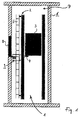
- FIG. 1 shows an elevator device 1 with a mobile scaffold 2 and a lift cage 3.
- the elevator cage 3 carries on its underside a camera 4.
- On the mobile scaffold 2 is a first Marking unit 5 attached.
- the elevator device 1 in turn is located in a building 6, the building 6 in turn comprises an elevator shaft 7, in which in turn the elevator device 1 is arranged.
- a shaft opening 8 In a wall of the building 6, which adjoins the elevator shaft 7, there is again a shaft opening 8.
- a second marking unit 9 is attached to the wall of the building 6.
- This embodiment is a preferred embodiment.
- the camera 4 is designed as an image sensor to basically detect and read both the first and the second marking unit. Persons can pass through a shaft opening 8 in the car 3, if this is at the appropriate height, more precisely at the corresponding position in height of the shaft opening 8. In the car 3, the persons can be transported in the vertical direction.
- the elevator cage 3 in turn is supported and guided by the chassis 2. Furthermore, the car 3 includes doors that automatically open and close when the car has reached a corresponding position, for example at the level of the shaft opening 8.
- the camera 4 When driving the elevator cage 3 in the vertical direction, the camera 4 receives corresponding images of the first measuring unit. These image information received by the first measuring unit are processed in the evaluation unit (not shown) and finally result in a position specification of the elevator car 3 within the chassis 2. Both the second marking unit and the first marking unit contain a barcode or 2-D code to be read out , The image area which the camera 4 detects, however, also makes it possible to read the second marking unit if it can be detected by the camera 4, which in turn depends on the position of the elevator cage 3. As in FIG. 1 illustrated, the camera 4 can then detect the second marking unit when the car 3 is located in the region of the shaft opening 8.
- Both the second marking unit and the camera 4 on the elevator car 3 are mounted so that the second marking unit at the shaft opening 8 can be read when the elevator car 3 is approximately 20 centimeters above or below the normal position at the level of the shaft opening 8, in usually takes a step out of the car. This is the case when the bottom of the car is at a level with the ground at the shaft opening 8.
- This zone 20 centimeters above to 20 centimeters below the normal holding position at the level of the shaft opening 8 in turn forms an unlocking zone.
- an emergency release can take place in permissible manner. Such an emergency release is necessary when the car 3 stops suddenly, for example as a result of an unforeseen event, a power failure, a blockage of the elevator or the like.
- the persons can then be released from the pull-out basket 3 without any special danger, if this is located in a corresponding zone which is located close enough to the shaft opening 8.
- this zone the unlocking zone, is located about 20 centimeters above or below the shaft opening 8.
- the first marking unit is formed as a band carrying the bar code; Meanwhile, the second marking unit is formed as a 2-D code, wherein the marking unit is formed by a marking piece.
- these marking units can be formed by an adhesive strip which carries the corresponding marking or the corresponding bar or 2-D code.
- FIG. 3 shows an example of a corresponding marking unit, namely a code tape 10.
- the code tape for attachment as a second marking unit provided directly to a building, for example, the area 11 can serve as floor coding, the area 12 as a position coding and the area 13 as unlocking coding.
- marking lines 14 may also be present.
- the marker lines 14 may occur at periodic intervals.
- the code tape 10, 11 itself consists of a reflective film, with corresponding black lines, areas or dots for coding are printed on it.
- the film is z. B. glued to a sheet or piece of metal and sealed for protection.
Landscapes
- Engineering & Computer Science (AREA)
- Automation & Control Theory (AREA)
- Computer Networks & Wireless Communication (AREA)
- Elevator Control (AREA)
- Indicating And Signalling Devices For Elevators (AREA)
- Lock And Its Accessories (AREA)
- Cage And Drive Apparatuses For Elevators (AREA)
Priority Applications (4)
| Application Number | Priority Date | Filing Date | Title |
|---|---|---|---|
| EP11005240.4A EP2540651B1 (de) | 2011-06-28 | 2011-06-28 | Aufzugvorrichtung, Gebäude und Positionsbestimmungsvorrichtung |
| US13/530,168 US8857572B2 (en) | 2011-06-28 | 2012-06-22 | Elevator position detection with optical marking units |
| CN201210215927.8A CN102849551B (zh) | 2011-06-28 | 2012-06-27 | 电梯装置、建筑物和位置确定装置 |
| JP2012145673A JP2013010638A (ja) | 2011-06-28 | 2012-06-28 | エレベータ装置、建物、及び位置決定デバイス |
Applications Claiming Priority (1)
| Application Number | Priority Date | Filing Date | Title |
|---|---|---|---|
| EP11005240.4A EP2540651B1 (de) | 2011-06-28 | 2011-06-28 | Aufzugvorrichtung, Gebäude und Positionsbestimmungsvorrichtung |
Publications (2)
| Publication Number | Publication Date |
|---|---|
| EP2540651A1 EP2540651A1 (de) | 2013-01-02 |
| EP2540651B1 true EP2540651B1 (de) | 2013-12-18 |
Family
ID=44993435
Family Applications (1)
| Application Number | Title | Priority Date | Filing Date |
|---|---|---|---|
| EP11005240.4A Active EP2540651B1 (de) | 2011-06-28 | 2011-06-28 | Aufzugvorrichtung, Gebäude und Positionsbestimmungsvorrichtung |
Country Status (4)
| Country | Link |
|---|---|
| US (1) | US8857572B2 (enExample) |
| EP (1) | EP2540651B1 (enExample) |
| JP (1) | JP2013010638A (enExample) |
| CN (1) | CN102849551B (enExample) |
Families Citing this family (36)
| Publication number | Priority date | Publication date | Assignee | Title |
|---|---|---|---|---|
| WO2012008944A1 (en) * | 2010-07-12 | 2012-01-19 | Otis Elevator Company | Speed and position detection system |
| RU2587283C2 (ru) * | 2010-12-17 | 2016-06-20 | Инвентио Аг | Контрольное устройство для обнаружения нежелательного выхода кабины лифта из неподвижного состояния |
| US10399817B2 (en) * | 2013-03-01 | 2019-09-03 | Mitsubishi Electric Corporation | Elevator car position detection device |
| EP2842899B1 (de) * | 2013-08-29 | 2016-11-02 | Cedes AG | Messband für eine Aufzugvorrichtung |
| US9469501B2 (en) * | 2013-10-05 | 2016-10-18 | Thyssenkrupp Elevator Corporation | Elevator positioning clip system and method |
| US9359170B2 (en) | 2013-10-14 | 2016-06-07 | Cedes Ag | Coding device and position-determining device and position-determining method |
| CN104760853A (zh) * | 2014-03-11 | 2015-07-08 | 北京博锐尚格节能技术股份有限公司 | 一种电梯运行监控方法、装置及系统 |
| CN106068237A (zh) * | 2014-03-19 | 2016-11-02 | 奥的斯电梯公司 | 用于监测至少一个门,尤其是电梯门的移动的方法和装置 |
| CN106573760A (zh) | 2014-08-22 | 2017-04-19 | 奥的斯电梯公司 | 厅门锁定系统和控制进入电梯竖井的方法 |
| US11097923B2 (en) | 2014-10-14 | 2021-08-24 | Xicore Inc. | Systems and methods for actively monitoring and controlling lift devices |
| CN107148392B (zh) | 2014-10-21 | 2020-09-11 | 因温特奥股份公司 | 具有非中心的电子安全系统的电梯 |
| TWI673229B (zh) * | 2014-12-02 | 2019-10-01 | 瑞士商伊文修股份有限公司 | 用於判定電梯車廂位置的方法和系統以及電梯系統 |
| TWI675791B (zh) * | 2014-12-15 | 2019-11-01 | 瑞士商伊文修股份有限公司 | 再修整升降機之升降井材料之表面結構的方法、升降機組件及升降機 |
| TWI675792B (zh) * | 2014-12-16 | 2019-11-01 | 瑞士商伊文修股份有限公司 | 用於電梯的位置判定系統及具有位置判定系統的電梯 |
| JP6399404B2 (ja) | 2015-03-20 | 2018-10-03 | フジテック株式会社 | エレベータ用のかご横揺れ抑制装置及びかご横揺れ抑制方法 |
| EP3328769B1 (de) * | 2015-07-30 | 2022-03-16 | Inventio AG | Verriegelungssystem für kabinentüre |
| CN105800411A (zh) * | 2016-04-14 | 2016-07-27 | 上海之跃信息科技有限公司 | 一种测量电梯运动的装置、方法和系统 |
| ES2870974T3 (es) * | 2017-05-12 | 2021-10-28 | Otis Elevator Co | Sistemas y métodos de inspección de ascensor automático |
| US10577222B2 (en) | 2017-05-12 | 2020-03-03 | Otis Elevator Company | Coded elevator inspection and positioning systems and methods |
| US10577221B2 (en) | 2017-05-12 | 2020-03-03 | Otis Elevator Company | Imaging inspection systems and methods for elevator landing doors |
| US10479648B2 (en) | 2017-05-12 | 2019-11-19 | Otis Elevator Company | Automatic elevator inspection systems and methods |
| AU2018293703B2 (en) | 2017-06-27 | 2021-05-27 | Inventio Ag | Position-determining system and method for determining a car postion of a lift car |
| AU2018298657B2 (en) * | 2017-07-14 | 2021-07-01 | Inventio Ag | Method for configuring security related configuration parameters in a passenger transport installation |
| EP3434634B2 (en) | 2017-07-25 | 2024-07-03 | Otis Elevator Company | Elevator safety device |
| US11161714B2 (en) * | 2018-03-02 | 2021-11-02 | Otis Elevator Company | Landing identification system to determine a building landing reference for an elevator |
| WO2019206644A1 (de) * | 2018-04-24 | 2019-10-31 | Inventio Ag | Positionsbestimmungssystem und verfahren zur ermittlung einer kabinenposition einer aufzugkabine |
| US11981538B2 (en) * | 2018-08-24 | 2024-05-14 | Mitsubishi Electric Corporation | Marking positioning device for elevator |
| CN112408136B (zh) * | 2019-04-30 | 2023-08-01 | 上海三菱电梯有限公司 | 轿厢绝对位置测量系统的校正装置的性能检测系统及方法 |
| CN110092253B (zh) * | 2019-04-30 | 2021-07-30 | 上海三菱电梯有限公司 | 对轿厢绝对位置测量系统的标定位置进行校正的系统及方法 |
| AU2020306683B2 (en) * | 2019-06-28 | 2024-05-02 | Inventio Ag | Method and device for determining multiple absolute cabin positions of an elevator cabin within a shaft of an elevator arrangement |
| EP3838825B1 (de) | 2019-12-20 | 2023-01-25 | Cedes AG | Dehnungssensor für ein positionsmessband eines aufzuges |
| US12116025B2 (en) * | 2020-01-21 | 2024-10-15 | Alstom Transport Technologies | Method for controlling the vertical position of a vehicle and associated control assembly |
| BR112022017657A2 (pt) * | 2020-03-04 | 2022-11-08 | Grimm Felix | Fita métrica para instalações de elevador |
| CN111591848A (zh) * | 2020-05-29 | 2020-08-28 | 西人马(厦门)科技有限公司 | 一种电梯楼层识别系统及方法 |
| US20250019203A1 (en) * | 2023-07-12 | 2025-01-16 | Otis Elevator Company | Dust mitigation for optical position reference system of an elevator system |
| DE102024132336A1 (de) * | 2024-11-06 | 2025-11-06 | Tk Elevator Innovation And Operations Gmbh | Fahrkorb, Aufzugsanlage und Verfahren zum Betreiben der Aufzugsanlage |
Citations (1)
| Publication number | Priority date | Publication date | Assignee | Title |
|---|---|---|---|---|
| US20020104716A1 (en) * | 2000-12-11 | 2002-08-08 | Otis Elevator Company | Absolute position reference system for an elevator |
Family Cites Families (17)
| Publication number | Priority date | Publication date | Assignee | Title |
|---|---|---|---|---|
| JPS6168073U (enExample) * | 1984-10-11 | 1986-05-09 | ||
| US5135081A (en) * | 1991-05-01 | 1992-08-04 | United States Elevator Corp. | Elevator position sensing system using coded vertical tape |
| JPH07157220A (ja) * | 1993-12-08 | 1995-06-20 | Hitachi Ltd | エレベータの位置検出装置 |
| CA2165247C (en) * | 1995-01-20 | 2006-05-23 | Bernhard Gerstenkorn | Method and equipment for the production of shaft information data of a lift shaft |
| US5889239A (en) * | 1996-11-04 | 1999-03-30 | Otis Elevator Company | Method for monitoring elevator leveling performance with improved accuracy |
| US5925859A (en) * | 1997-08-06 | 1999-07-20 | Interface Products Co., Inc. | Landing control system |
| US6128116A (en) * | 1997-12-31 | 2000-10-03 | Otis Elevator Company | Retroreflective elevator hoistway position sensor |
| JP2000351544A (ja) * | 1999-06-11 | 2000-12-19 | Toshiba Elevator Co Ltd | エレベータの位置検出装置 |
| SG96681A1 (en) * | 2001-02-20 | 2003-06-16 | Inventio Ag | Method of generating hoistway information to serve an elevator control |
| WO2002096788A1 (de) * | 2001-05-31 | 2002-12-05 | Inventio Ag | Einrichtung zur ermittlung der position einer schienengeführten aufzugskabine mit codeträger |
| TW555681B (en) * | 2001-07-31 | 2003-10-01 | Inventio Ag | Lift installation with equipment for ascertaining the cage position |
| CN1878714A (zh) * | 2003-10-31 | 2006-12-13 | 奥蒂斯电梯公司 | 基于rf id和低分辨率ccd传感器的定位系统 |
| JP2007521211A (ja) * | 2003-11-26 | 2007-08-02 | オーチス エレベータ カンパニー | 自動調整式エレベータ位置決め基準システムの装置ならびに方法 |
| CN1997580B (zh) * | 2004-08-10 | 2010-04-28 | 奥蒂斯电梯公司 | 电梯轿厢定位确定系统 |
| ES2293392T5 (es) * | 2005-01-07 | 2011-07-20 | Thyssenkrupp Elevator Ag | Ascensor con sistema de control. |
| DE502005000701D1 (de) * | 2005-03-05 | 2007-06-21 | Thyssenkrupp Aufzugswerke Gmbh | Aufzuganlage |
| EP2657171B1 (de) * | 2012-04-26 | 2014-06-11 | Cedes AG | Aufzuganlage, Markierungsvorrichtung und Messeinrichtung |
-
2011
- 2011-06-28 EP EP11005240.4A patent/EP2540651B1/de active Active
-
2012
- 2012-06-22 US US13/530,168 patent/US8857572B2/en active Active
- 2012-06-27 CN CN201210215927.8A patent/CN102849551B/zh active Active
- 2012-06-28 JP JP2012145673A patent/JP2013010638A/ja active Pending
Patent Citations (1)
| Publication number | Priority date | Publication date | Assignee | Title |
|---|---|---|---|---|
| US20020104716A1 (en) * | 2000-12-11 | 2002-08-08 | Otis Elevator Company | Absolute position reference system for an elevator |
Also Published As
| Publication number | Publication date |
|---|---|
| JP2013010638A (ja) | 2013-01-17 |
| US20130001023A1 (en) | 2013-01-03 |
| CN102849551A (zh) | 2013-01-02 |
| CN102849551B (zh) | 2017-04-26 |
| US8857572B2 (en) | 2014-10-14 |
| EP2540651A1 (de) | 2013-01-02 |
Similar Documents
| Publication | Publication Date | Title |
|---|---|---|
| EP2540651B1 (de) | Aufzugvorrichtung, Gebäude und Positionsbestimmungsvorrichtung | |
| EP2657171B1 (de) | Aufzuganlage, Markierungsvorrichtung und Messeinrichtung | |
| EP2037224B1 (de) | Verfahren und Vorrichtung zum Bestimmen der Position eines Fahrzeugs, Computerprogramm und Computerprogrammprodukt | |
| EP3377436B1 (de) | Verfahren zum bestimmen von informationen über in einem aufzugschacht aufgenommene aufzugkomponenten und aufzuganlage | |
| DE102015208058B4 (de) | Automatisiertes Parksystem | |
| EP2562117B1 (de) | Aufzugvorrichtung mit Positionsbestimmungsvorrichtung | |
| EP3935000B1 (de) | Messvorrichtung zum vermessen eines aufzugschachts und verwendung der messvorrichtung zum vermessen eines aufzugschachts | |
| WO2012110343A1 (de) | Verfahren zur autarken lokalisierung eines fahrerlosen, motorisierten fahrzeugs | |
| WO2016087528A1 (de) | Verfahren und system zur bestimmung der position einer aufzugskabine | |
| EP2171556B1 (de) | Vorrichtung und verfahren zur positions- und orientierungsbestimmung | |
| EP2546180A1 (de) | Aufzugsanlage und Verfahren zur Detektion der Position der Aufzugskabine. | |
| EP3898478A1 (de) | Aufzuganlage mit laserdistanzmesseinrichtung | |
| EP2017574A2 (de) | Verfahren zur geodätischen Überwachung von Schienen | |
| WO2016096824A1 (de) | Verfahren und system zur bestimmung der position und der orientierung einer aufzugskabine | |
| WO2011134773A1 (de) | Verfahren und vorrichtung zur installation eines aufzuges in einem aufzugsschacht | |
| EP3822211B1 (de) | Vorrichtung und verfahren zur bestimmung eines zustands eines aufzugs | |
| EP1288155A1 (de) | Verfahren und Vorrichtung zur Ermittlung des Zustandes eines Schienenstranges | |
| WO2006072617A2 (de) | System zur überwachung des bereichs zwischen zug und plattformkante | |
| DE102008032786A1 (de) | Vorrichtung und Verfahren zum Bestimmen einer Position eines Fahrzeugs | |
| DE102007034154A1 (de) | Parksystem zum automatisierten Ein- und Auslagern von Kraftfahrzeugen | |
| EP3258218B1 (de) | Personen- und/oder gütertransportsystem | |
| EP2572993B1 (de) | Prüfvorrichtung für Gangways | |
| EP0389823A2 (de) | Vorrichtung zum Messen von Verschiebungen und Deformationen von Bauwerken | |
| DE19520795C3 (de) | Schaltvorrichtung für Hubelemente | |
| EP1315982A1 (de) | Laser-entfernungsmesser für antikollisionsanwendungen |
Legal Events
| Date | Code | Title | Description |
|---|---|---|---|
| PUAI | Public reference made under article 153(3) epc to a published international application that has entered the european phase |
Free format text: ORIGINAL CODE: 0009012 |
|
| 17P | Request for examination filed |
Effective date: 20110628 |
|
| AK | Designated contracting states |
Kind code of ref document: A1 Designated state(s): AL AT BE BG CH CY CZ DE DK EE ES FI FR GB GR HR HU IE IS IT LI LT LU LV MC MK MT NL NO PL PT RO RS SE SI SK SM TR |
|
| AX | Request for extension of the european patent |
Extension state: BA ME |
|
| GRAP | Despatch of communication of intention to grant a patent |
Free format text: ORIGINAL CODE: EPIDOSNIGR1 |
|
| INTG | Intention to grant announced |
Effective date: 20130725 |
|
| GRAS | Grant fee paid |
Free format text: ORIGINAL CODE: EPIDOSNIGR3 |
|
| GRAA | (expected) grant |
Free format text: ORIGINAL CODE: 0009210 |
|
| AK | Designated contracting states |
Kind code of ref document: B1 Designated state(s): AL AT BE BG CH CY CZ DE DK EE ES FI FR GB GR HR HU IE IS IT LI LT LU LV MC MK MT NL NO PL PT RO RS SE SI SK SM TR |
|
| REG | Reference to a national code |
Ref country code: GB Ref legal event code: FG4D Free format text: NOT ENGLISH |
|
| REG | Reference to a national code |
Ref country code: CH Ref legal event code: EP |
|
| REG | Reference to a national code |
Ref country code: AT Ref legal event code: REF Ref document number: 645531 Country of ref document: AT Kind code of ref document: T Effective date: 20140115 |
|
| REG | Reference to a national code |
Ref country code: IE Ref legal event code: FG4D Free format text: LANGUAGE OF EP DOCUMENT: GERMAN |
|
| REG | Reference to a national code |
Ref country code: DE Ref legal event code: R096 Ref document number: 502011001817 Country of ref document: DE Effective date: 20140213 |
|
| REG | Reference to a national code |
Ref country code: CH Ref legal event code: NV Representative=s name: KELLER AND PARTNER PATENTANWAELTE AG, CH |
|
| REG | Reference to a national code |
Ref country code: NL Ref legal event code: VDEP Effective date: 20131218 |
|
| PG25 | Lapsed in a contracting state [announced via postgrant information from national office to epo] |
Ref country code: NO Free format text: LAPSE BECAUSE OF FAILURE TO SUBMIT A TRANSLATION OF THE DESCRIPTION OR TO PAY THE FEE WITHIN THE PRESCRIBED TIME-LIMIT Effective date: 20140318 Ref country code: LT Free format text: LAPSE BECAUSE OF FAILURE TO SUBMIT A TRANSLATION OF THE DESCRIPTION OR TO PAY THE FEE WITHIN THE PRESCRIBED TIME-LIMIT Effective date: 20131218 Ref country code: SE Free format text: LAPSE BECAUSE OF FAILURE TO SUBMIT A TRANSLATION OF THE DESCRIPTION OR TO PAY THE FEE WITHIN THE PRESCRIBED TIME-LIMIT Effective date: 20131218 Ref country code: HR Free format text: LAPSE BECAUSE OF FAILURE TO SUBMIT A TRANSLATION OF THE DESCRIPTION OR TO PAY THE FEE WITHIN THE PRESCRIBED TIME-LIMIT Effective date: 20131218 |
|
| REG | Reference to a national code |
Ref country code: LT Ref legal event code: MG4D |
|
| PG25 | Lapsed in a contracting state [announced via postgrant information from national office to epo] |
Ref country code: RS Free format text: LAPSE BECAUSE OF FAILURE TO SUBMIT A TRANSLATION OF THE DESCRIPTION OR TO PAY THE FEE WITHIN THE PRESCRIBED TIME-LIMIT Effective date: 20131218 Ref country code: LV Free format text: LAPSE BECAUSE OF FAILURE TO SUBMIT A TRANSLATION OF THE DESCRIPTION OR TO PAY THE FEE WITHIN THE PRESCRIBED TIME-LIMIT Effective date: 20131218 |
|
| PG25 | Lapsed in a contracting state [announced via postgrant information from national office to epo] |
Ref country code: IS Free format text: LAPSE BECAUSE OF FAILURE TO SUBMIT A TRANSLATION OF THE DESCRIPTION OR TO PAY THE FEE WITHIN THE PRESCRIBED TIME-LIMIT Effective date: 20140418 Ref country code: EE Free format text: LAPSE BECAUSE OF FAILURE TO SUBMIT A TRANSLATION OF THE DESCRIPTION OR TO PAY THE FEE WITHIN THE PRESCRIBED TIME-LIMIT Effective date: 20131218 |
|
| PG25 | Lapsed in a contracting state [announced via postgrant information from national office to epo] |
Ref country code: RO Free format text: LAPSE BECAUSE OF FAILURE TO SUBMIT A TRANSLATION OF THE DESCRIPTION OR TO PAY THE FEE WITHIN THE PRESCRIBED TIME-LIMIT Effective date: 20131218 Ref country code: PL Free format text: LAPSE BECAUSE OF FAILURE TO SUBMIT A TRANSLATION OF THE DESCRIPTION OR TO PAY THE FEE WITHIN THE PRESCRIBED TIME-LIMIT Effective date: 20131218 Ref country code: CY Free format text: LAPSE BECAUSE OF FAILURE TO SUBMIT A TRANSLATION OF THE DESCRIPTION OR TO PAY THE FEE WITHIN THE PRESCRIBED TIME-LIMIT Effective date: 20131218 Ref country code: NL Free format text: LAPSE BECAUSE OF FAILURE TO SUBMIT A TRANSLATION OF THE DESCRIPTION OR TO PAY THE FEE WITHIN THE PRESCRIBED TIME-LIMIT Effective date: 20131218 Ref country code: ES Free format text: LAPSE BECAUSE OF FAILURE TO SUBMIT A TRANSLATION OF THE DESCRIPTION OR TO PAY THE FEE WITHIN THE PRESCRIBED TIME-LIMIT Effective date: 20131218 Ref country code: PT Free format text: LAPSE BECAUSE OF FAILURE TO SUBMIT A TRANSLATION OF THE DESCRIPTION OR TO PAY THE FEE WITHIN THE PRESCRIBED TIME-LIMIT Effective date: 20140418 Ref country code: SK Free format text: LAPSE BECAUSE OF FAILURE TO SUBMIT A TRANSLATION OF THE DESCRIPTION OR TO PAY THE FEE WITHIN THE PRESCRIBED TIME-LIMIT Effective date: 20131218 Ref country code: CZ Free format text: LAPSE BECAUSE OF FAILURE TO SUBMIT A TRANSLATION OF THE DESCRIPTION OR TO PAY THE FEE WITHIN THE PRESCRIBED TIME-LIMIT Effective date: 20131218 |
|
| REG | Reference to a national code |
Ref country code: DE Ref legal event code: R097 Ref document number: 502011001817 Country of ref document: DE |
|
| PLBE | No opposition filed within time limit |
Free format text: ORIGINAL CODE: 0009261 |
|
| STAA | Information on the status of an ep patent application or granted ep patent |
Free format text: STATUS: NO OPPOSITION FILED WITHIN TIME LIMIT |
|
| PG25 | Lapsed in a contracting state [announced via postgrant information from national office to epo] |
Ref country code: DK Free format text: LAPSE BECAUSE OF FAILURE TO SUBMIT A TRANSLATION OF THE DESCRIPTION OR TO PAY THE FEE WITHIN THE PRESCRIBED TIME-LIMIT Effective date: 20131218 |
|
| 26N | No opposition filed |
Effective date: 20140919 |
|
| REG | Reference to a national code |
Ref country code: DE Ref legal event code: R097 Ref document number: 502011001817 Country of ref document: DE Effective date: 20140919 |
|
| PG25 | Lapsed in a contracting state [announced via postgrant information from national office to epo] |
Ref country code: MC Free format text: LAPSE BECAUSE OF FAILURE TO SUBMIT A TRANSLATION OF THE DESCRIPTION OR TO PAY THE FEE WITHIN THE PRESCRIBED TIME-LIMIT Effective date: 20131218 Ref country code: LU Free format text: LAPSE BECAUSE OF FAILURE TO SUBMIT A TRANSLATION OF THE DESCRIPTION OR TO PAY THE FEE WITHIN THE PRESCRIBED TIME-LIMIT Effective date: 20140628 |
|
| REG | Reference to a national code |
Ref country code: IE Ref legal event code: MM4A |
|
| REG | Reference to a national code |
Ref country code: FR Ref legal event code: ST Effective date: 20150227 |
|
| REG | Reference to a national code |
Ref country code: CH Ref legal event code: PCAR Free format text: NEW ADDRESS: EIGERSTRASSE 2 POSTFACH, 3000 BERN 14 (CH) |
|
| PG25 | Lapsed in a contracting state [announced via postgrant information from national office to epo] |
Ref country code: IE Free format text: LAPSE BECAUSE OF NON-PAYMENT OF DUE FEES Effective date: 20140628 |
|
| PG25 | Lapsed in a contracting state [announced via postgrant information from national office to epo] |
Ref country code: SI Free format text: LAPSE BECAUSE OF FAILURE TO SUBMIT A TRANSLATION OF THE DESCRIPTION OR TO PAY THE FEE WITHIN THE PRESCRIBED TIME-LIMIT Effective date: 20131218 Ref country code: FR Free format text: LAPSE BECAUSE OF NON-PAYMENT OF DUE FEES Effective date: 20140630 |
|
| GBPC | Gb: european patent ceased through non-payment of renewal fee |
Effective date: 20150628 |
|
| PG25 | Lapsed in a contracting state [announced via postgrant information from national office to epo] |
Ref country code: MT Free format text: LAPSE BECAUSE OF FAILURE TO SUBMIT A TRANSLATION OF THE DESCRIPTION OR TO PAY THE FEE WITHIN THE PRESCRIBED TIME-LIMIT Effective date: 20131218 |
|
| PG25 | Lapsed in a contracting state [announced via postgrant information from national office to epo] |
Ref country code: SM Free format text: LAPSE BECAUSE OF FAILURE TO SUBMIT A TRANSLATION OF THE DESCRIPTION OR TO PAY THE FEE WITHIN THE PRESCRIBED TIME-LIMIT Effective date: 20131218 Ref country code: GB Free format text: LAPSE BECAUSE OF NON-PAYMENT OF DUE FEES Effective date: 20150628 |
|
| PG25 | Lapsed in a contracting state [announced via postgrant information from national office to epo] |
Ref country code: IT Free format text: LAPSE BECAUSE OF FAILURE TO SUBMIT A TRANSLATION OF THE DESCRIPTION OR TO PAY THE FEE WITHIN THE PRESCRIBED TIME-LIMIT Effective date: 20131218 Ref country code: GR Free format text: LAPSE BECAUSE OF FAILURE TO SUBMIT A TRANSLATION OF THE DESCRIPTION OR TO PAY THE FEE WITHIN THE PRESCRIBED TIME-LIMIT Effective date: 20140319 Ref country code: BG Free format text: LAPSE BECAUSE OF FAILURE TO SUBMIT A TRANSLATION OF THE DESCRIPTION OR TO PAY THE FEE WITHIN THE PRESCRIBED TIME-LIMIT Effective date: 20131218 |
|
| PG25 | Lapsed in a contracting state [announced via postgrant information from national office to epo] |
Ref country code: TR Free format text: LAPSE BECAUSE OF FAILURE TO SUBMIT A TRANSLATION OF THE DESCRIPTION OR TO PAY THE FEE WITHIN THE PRESCRIBED TIME-LIMIT Effective date: 20131218 Ref country code: BE Free format text: LAPSE BECAUSE OF FAILURE TO SUBMIT A TRANSLATION OF THE DESCRIPTION OR TO PAY THE FEE WITHIN THE PRESCRIBED TIME-LIMIT Effective date: 20140630 Ref country code: HU Free format text: LAPSE BECAUSE OF FAILURE TO SUBMIT A TRANSLATION OF THE DESCRIPTION OR TO PAY THE FEE WITHIN THE PRESCRIBED TIME-LIMIT; INVALID AB INITIO Effective date: 20110628 |
|
| PGFP | Annual fee paid to national office [announced via postgrant information from national office to epo] |
Ref country code: FI Payment date: 20160621 Year of fee payment: 6 |
|
| PG25 | Lapsed in a contracting state [announced via postgrant information from national office to epo] |
Ref country code: AT Free format text: LAPSE BECAUSE OF FAILURE TO SUBMIT A TRANSLATION OF THE DESCRIPTION OR TO PAY THE FEE WITHIN THE PRESCRIBED TIME-LIMIT Effective date: 20131218 |
|
| REG | Reference to a national code |
Ref country code: AT Ref legal event code: MM01 Ref document number: 645531 Country of ref document: AT Kind code of ref document: T Effective date: 20160628 |
|
| PG25 | Lapsed in a contracting state [announced via postgrant information from national office to epo] |
Ref country code: AT Free format text: LAPSE BECAUSE OF FAILURE TO SUBMIT A TRANSLATION OF THE DESCRIPTION OR TO PAY THE FEE WITHIN THE PRESCRIBED TIME-LIMIT Effective date: 20160628 |
|
| PG25 | Lapsed in a contracting state [announced via postgrant information from national office to epo] |
Ref country code: FI Free format text: LAPSE BECAUSE OF NON-PAYMENT OF DUE FEES Effective date: 20170628 |
|
| PG25 | Lapsed in a contracting state [announced via postgrant information from national office to epo] |
Ref country code: MK Free format text: LAPSE BECAUSE OF FAILURE TO SUBMIT A TRANSLATION OF THE DESCRIPTION OR TO PAY THE FEE WITHIN THE PRESCRIBED TIME-LIMIT Effective date: 20131218 |
|
| PG25 | Lapsed in a contracting state [announced via postgrant information from national office to epo] |
Ref country code: AL Free format text: LAPSE BECAUSE OF FAILURE TO SUBMIT A TRANSLATION OF THE DESCRIPTION OR TO PAY THE FEE WITHIN THE PRESCRIBED TIME-LIMIT Effective date: 20131218 |
|
| REG | Reference to a national code |
Ref country code: CH Ref legal event code: PFA Owner name: CEDES AG, CH Free format text: FORMER OWNER: CEDES AG, CH |
|
| P01 | Opt-out of the competence of the unified patent court (upc) registered |
Effective date: 20230519 |
|
| REG | Reference to a national code |
Ref country code: DE Ref legal event code: R082 Ref document number: 502011001817 Country of ref document: DE Representative=s name: RAVENSPAT PATENTANWAELTE PARTNERSCHAFT MBB, DE |
|
| PGFP | Annual fee paid to national office [announced via postgrant information from national office to epo] |
Ref country code: DE Payment date: 20250618 Year of fee payment: 15 |
|
| PGFP | Annual fee paid to national office [announced via postgrant information from national office to epo] |
Ref country code: CH Payment date: 20250701 Year of fee payment: 15 |