EP2540651B1 - Lift device, building and positioning device - Google Patents
Lift device, building and positioning device Download PDFInfo
- Publication number
- EP2540651B1 EP2540651B1 EP11005240.4A EP11005240A EP2540651B1 EP 2540651 B1 EP2540651 B1 EP 2540651B1 EP 11005240 A EP11005240 A EP 11005240A EP 2540651 B1 EP2540651 B1 EP 2540651B1
- Authority
- EP
- European Patent Office
- Prior art keywords
- lift
- marking unit
- unit
- building
- marking
- Prior art date
- Legal status (The legal status is an assumption and is not a legal conclusion. Google has not performed a legal analysis and makes no representation as to the accuracy of the status listed.)
- Active
Links
- 238000011156 evaluation Methods 0.000 claims abstract description 19
- 238000005259 measurement Methods 0.000 claims abstract description 4
- 238000001514 detection method Methods 0.000 claims description 19
- 238000012423 maintenance Methods 0.000 description 4
- 239000003550 marker Substances 0.000 description 3
- 230000032683 aging Effects 0.000 description 2
- 230000007547 defect Effects 0.000 description 2
- 230000000694 effects Effects 0.000 description 2
- 230000035882 stress Effects 0.000 description 2
- 239000000853 adhesive Substances 0.000 description 1
- 230000001070 adhesive effect Effects 0.000 description 1
- 238000010276 construction Methods 0.000 description 1
- 238000011109 contamination Methods 0.000 description 1
- 230000001419 dependent effect Effects 0.000 description 1
- 238000013461 design Methods 0.000 description 1
- 238000011161 development Methods 0.000 description 1
- 230000018109 developmental process Effects 0.000 description 1
- 238000006073 displacement reaction Methods 0.000 description 1
- 239000000428 dust Substances 0.000 description 1
- 238000005516 engineering process Methods 0.000 description 1
- 230000006870 function Effects 0.000 description 1
- 239000003673 groundwater Substances 0.000 description 1
- 238000009434 installation Methods 0.000 description 1
- 239000002184 metal Substances 0.000 description 1
- 230000000737 periodic effect Effects 0.000 description 1
- 238000012216 screening Methods 0.000 description 1
Images

Classifications
-
- B—PERFORMING OPERATIONS; TRANSPORTING
- B66—HOISTING; LIFTING; HAULING
- B66B—ELEVATORS; ESCALATORS OR MOVING WALKWAYS
- B66B1/00—Control systems of elevators in general
- B66B1/34—Details, e.g. call counting devices, data transmission from car to control system, devices giving information to the control system
- B66B1/3492—Position or motion detectors or driving means for the detector
-
- B—PERFORMING OPERATIONS; TRANSPORTING
- B66—HOISTING; LIFTING; HAULING
- B66B—ELEVATORS; ESCALATORS OR MOVING WALKWAYS
- B66B3/00—Applications of devices for indicating or signalling operating conditions of elevators
- B66B3/02—Position or depth indicators
- B66B3/023—Position or depth indicators characterised by their mounting position
Definitions
- the invention relates to an elevator device for the transport of persons and / or objects within an elevator shaft of a building or the like according to the preamble of claim 1 and a building according to the preamble of claim 7.
- Elevators or elevator systems for buildings are known from the prior art, in which the position of the elevator car of the elevator car is detected by means of a magnetic tape.
- This magnetic tape is regularly attached to the mobile scaffold or on a guide rail of the mobile scaffold.
- This mobile scaffold serves to guide or support the elevator cage, ie the mobile scaffold provides a guide for the elevator cage, in which the elevator cage is moved or can be moved.
- the object of the invention is to provide an elevator apparatus, a position determination apparatus or a building, in which an improved precise position determination of the elevator car is made possible taking into account that building structures can settle over time after they have been built.
- an elevator device is characterized in that the marking unit as a carrier of a bar code, in particular a 2-D code and the detection unit as an image sensor, in particular as a camera, are formed.
- the elevator device serves to transport persons and / or objects within an elevator shaft of a room structure or the like.
- a room structure can be a building.
- Under a building according to the invention is any kind of structure to understand, for example, a house, a high-rise, a tower, a hall, a stadium with a tribune, a warehouse, a transport or loading station or the like. But it can also be another, at least two floors comprehensive spatial structure.
- a spatial structure may, for example, also be a vehicle which has a building-like structure, for example a ship.
- elevator devices in mobile transport or lifting devices Such an elevator device has a lift cage in which the persons and / or objects to be transported can be accommodated. The elevator cage is moved within a mobile scaffold for storage or guidance of the elevator cage.
- the mobile scaffold is installed inside a lift shaft.
- a position determining device In order to determine the position of the elevator cage within the elevator shaft or with respect to the mobile platform, a position determining device is provided. This comprises at least one marking unit for marking the position, furthermore a detection unit for detecting or reading out the marking unit and an evaluation unit for evaluating the measured values of the detection unit.
- This evaluation unit can, for example be designed as an electronic unit, which outputs output measured values of the detection unit and uses this to determine therefrom a position indication of the position of the elevator cage with respect to the mobile scaffold or the position within the elevator shaft.
- the position determination can be improved.
- a bar code or a 2-D code makes it possible to carry out a simple and cost-effective marking.
- Such a mark can be printed, for example, simply and inexpensively.
- Such a mark can also be read out with standard scanners or other image sensors provided for this purpose. In addition, this allows a particularly error-free reading. Since the corresponding barcodes or 2-D codes can be imaged very sharply and can also be placed very precisely in relation to the mobile scaffold or the elevator shaft and on a very precise image sensor detection is possible, the position can also be determined very precisely become.
- barcodes or 2-D codes have a correspondingly high black-and-white contrast, these markers are regularly less susceptible to contamination such. By dust.
- a maintenance or error signal can be output, for example, from the evaluation unit, in which also the contrast can be determined.
- a barcode or 2-D code can advantageously be read without contact and is also practically wear-free.
- a correspondingly accurate detection is provided by image sensors having a corresponding optics such. have telecentric lenses allows. Furthermore, it is possible to provide the most compact and small image sensors available. Due to the simple and compact design it is possible that only small costs for the position determination occur. In addition, such a position determination allows low power consumption, since usually only a small power is required for the corresponding electronics.
- the marking unit is further formed as a band, this measure, allows a continuous marking of the position on the route of the elevator car.
- Each individual marking can be separated from the next marking by a corresponding symbolism, for example a separating strip, so that a fine screening is also made possible.
- the first marking unit is mounted on the mobile scaffold, in particular on a guide rail of the mobile scaffold.
- this measure also enables a simplified installation or maintenance.
- no influence must be taken into account with regard to a measurement that could be caused by a change in the distance between the marking strip and the sensor. In most cases, a small distance between the marking strip and the sensor makes it possible to determine the position precisely.
- Building structures can "settle" over time after they have been built, ie walls, for example, have their position change and move easily. Such changes are known in construction technology and building physics and caused for example by aging or stress. Also conceivable are changes due to seismic activity or other changes in the subsurface (caused, for example, by subsidence, by groundwater, etc.). However, these shifts are not always linear or even. If such a shift occurs, it may mean that the building is being moved in a different way than, for example, the chassis in which the elevator cage is being guided.
- a further advantage of the attachment of the marking unit to the mobile scaffold can consequently be that at least partial decoupling of the position of the marking unit from displacements of the building is made possible.
- a corresponding marking unit is attached directly to the building, for example to a wall of the building, this can change its relative position with respect to the detection by an image sensor of a lift cage movable in the mobile structure. If this effect were not taken into account, this could lead to the positioning being more inaccurate after a certain time, in which the building or individual walls move, than when installing the elevator; Accordingly, if appropriate, the shaft opening could no longer be approached precisely by the elevator car.
- the second marking unit is attached to the elevator shaft or to another part, for example a wall of the building.
- At least one first and one second marking unit are provided according to the invention.
- a second marking unit can be used as a reference mark for adjusting the accuracy of the first marking unit.
- the evaluation unit can perform such a comparison, if necessary automatically at certain time intervals.
- the elevator apparatus can determine whether with time between the first marking unit and the second Marking unit has made a change in relation to the relative position to each other. This can be used for maintenance purposes, but also for building security.
- a calibration of the position-determining device can thereby be carried out, so that an even more precise position determination is made possible. Such a calibration can be carried out in the evaluation unit.
- the second marking unit may, for example, be mounted near the shaft opening, for example per floor.
- a second marking unit can also be used to transmit further information.
- the second marking unit can be used to mark a specific zone on the route within the elevator shaft.
- the evaluation unit can in turn be designed to determine whether the car or the elevator car is located within this zone or not.
- a zone can be, for example, the area around a shaft opening in which it is possible to get out of persons located in the elevator cage.
- a shaft opening is present in each floor, optionally also two manhole openings, if, for example, an exit to opposite sides is possible.
- an unlocking device for unlocking a door or an exit hatch of the elevator car which is controllable by means of the evaluation device, be present.
- the purpose of such unlocking is to allow an emergency exit in case of a defect of the elevator, but only if the elevator car is located in the region of a shaft opening.
- the unlocking a Door of a shaft opening of the elevator shaft unlocked, so a door that is not directly attached to the elevator car.
- a control within the meaning of the invention means a control and / or control. For example, depending on whether the elevator car is within the zone, the unlocking device may or may not be activated.
- the detection unit may be arranged in an embodiment variant on and / or under the car. It is also conceivable that the detection unit is attached to another position on the car. This means that the marking unit is fixed, for example on the running rail or on the building itself, while the car, which can perform a movement relative to this marking unit, has the corresponding detection unit, which then depending on their position with respect to the Marker unit corresponding position information can supply the evaluation device. In principle, however, it is conceivable that the detection unit is also mounted, for example, laterally on the elevator car. In general, the position of the detection unit relative to the car, inter alia, in the evaluation of the position of the car by the evaluation device to be considered, d. H. this must be configured accordingly or preprogrammed accordingly.
- a building according to the invention with at least two floors is characterized in that an elevator device according to one of the preceding claims is provided.
- the second marking unit is attached to the building.
- a relation between the mobile scaffold or the rail of the mobile scaffold and the building is advantageously made possible in particular.
- this relative position between the building and the mobile scaffolding even at a non-uniform change at any time redetermined and recalibrated.
- a corresponding warning function for example, by the evaluation, is activated when this change in position is too strong.
- This second marking unit can also carry, for example, floor information and position information. For example, it may contain the number of the single floor in coded form.
- the position information can be represented in various ways: First, there is the possibility of point information, which can be used in principle for calibrating the code band, but also for calculating a position, for example, the zone in which an unlocking is to take place. Furthermore, an area information can be encoded, which z. B. enables direct detection of the unlocking zone. Such an area may be defined by a beginning and an end, for example, in the case of an unlocking zone, an area of about 20 cm below a manhole opening to 20 cm above a manhole opening. In principle, it is conceivable, for example, to detect the beginning or the end of an unlocking zone directly on the basis of a coding on the marking unit.
- a length information can be transmitted, which can be used for a calibration of the code band, but can also lead to increased accuracy, if the vernier principle is exploited. Accordingly, in principle both an indirect and a direct detection of the unlocking zone is conceivable.
- floor information can also be coded. Image sensors can basically be used to read out the first and also the second marking unit. The marker units can also be used to define a breakpoint of the elevator cage. The floor information can basically be omitted if a position can be assigned to the code read out from the marking unit by the memory of the evaluation unit.
- the corresponding information or allocation table is then corresponding to e.g. in the memory of the evaluation before deposit.
- the floor information may also be obtained by detecting a read-out breakpoint information and reading markings from an extreme position during a learning phase while driving. This measure enables good technical feasibility and cost-effective implementation.
- the second marking unit is arranged such that the zone marked by it forms an area around at least one of the shaft openings of the elevator shaft.
- This zone may, for example, serve as an unlocking zone, i. H.
- an emergency release can be made if the elevator stops, for example due to a technical defect or other unforeseen event. With the help of the emergency release then the doors can be brought in a safe for the persons or the transporting objects area through a manhole opening from the car. By this measure, the safety of the elevator device can be increased.
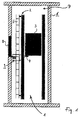
- FIG. 1 shows an elevator device 1 with a mobile scaffold 2 and a lift cage 3.
- the elevator cage 3 carries on its underside a camera 4.
- On the mobile scaffold 2 is a first Marking unit 5 attached.
- the elevator device 1 in turn is located in a building 6, the building 6 in turn comprises an elevator shaft 7, in which in turn the elevator device 1 is arranged.
- a shaft opening 8 In a wall of the building 6, which adjoins the elevator shaft 7, there is again a shaft opening 8.
- a second marking unit 9 is attached to the wall of the building 6.
- This embodiment is a preferred embodiment.
- the camera 4 is designed as an image sensor to basically detect and read both the first and the second marking unit. Persons can pass through a shaft opening 8 in the car 3, if this is at the appropriate height, more precisely at the corresponding position in height of the shaft opening 8. In the car 3, the persons can be transported in the vertical direction.
- the elevator cage 3 in turn is supported and guided by the chassis 2. Furthermore, the car 3 includes doors that automatically open and close when the car has reached a corresponding position, for example at the level of the shaft opening 8.
- the camera 4 When driving the elevator cage 3 in the vertical direction, the camera 4 receives corresponding images of the first measuring unit. These image information received by the first measuring unit are processed in the evaluation unit (not shown) and finally result in a position specification of the elevator car 3 within the chassis 2. Both the second marking unit and the first marking unit contain a barcode or 2-D code to be read out , The image area which the camera 4 detects, however, also makes it possible to read the second marking unit if it can be detected by the camera 4, which in turn depends on the position of the elevator cage 3. As in FIG. 1 illustrated, the camera 4 can then detect the second marking unit when the car 3 is located in the region of the shaft opening 8.
- Both the second marking unit and the camera 4 on the elevator car 3 are mounted so that the second marking unit at the shaft opening 8 can be read when the elevator car 3 is approximately 20 centimeters above or below the normal position at the level of the shaft opening 8, in usually takes a step out of the car. This is the case when the bottom of the car is at a level with the ground at the shaft opening 8.
- This zone 20 centimeters above to 20 centimeters below the normal holding position at the level of the shaft opening 8 in turn forms an unlocking zone.
- an emergency release can take place in permissible manner. Such an emergency release is necessary when the car 3 stops suddenly, for example as a result of an unforeseen event, a power failure, a blockage of the elevator or the like.
- the persons can then be released from the pull-out basket 3 without any special danger, if this is located in a corresponding zone which is located close enough to the shaft opening 8.
- this zone the unlocking zone, is located about 20 centimeters above or below the shaft opening 8.
- the first marking unit is formed as a band carrying the bar code; Meanwhile, the second marking unit is formed as a 2-D code, wherein the marking unit is formed by a marking piece.
- these marking units can be formed by an adhesive strip which carries the corresponding marking or the corresponding bar or 2-D code.
- FIG. 3 shows an example of a corresponding marking unit, namely a code tape 10.
- the code tape for attachment as a second marking unit provided directly to a building, for example, the area 11 can serve as floor coding, the area 12 as a position coding and the area 13 as unlocking coding.
- marking lines 14 may also be present.
- the marker lines 14 may occur at periodic intervals.
- the code tape 10, 11 itself consists of a reflective film, with corresponding black lines, areas or dots for coding are printed on it.
- the film is z. B. glued to a sheet or piece of metal and sealed for protection.
Landscapes
- Engineering & Computer Science (AREA)
- Automation & Control Theory (AREA)
- Computer Networks & Wireless Communication (AREA)
- Elevator Control (AREA)
- Indicating And Signalling Devices For Elevators (AREA)
- Cage And Drive Apparatuses For Elevators (AREA)
- Lock And Its Accessories (AREA)
Abstract
Description
Die Erfindung betrifft eine Aufzugvorrichtung zur Beförderung von Personen und/oder Gegenständen innerhalb eines Aufzugsschachtes eines Gebäudes oder dergleichen nach dem Oberbegriff des Anspruchs 1 sowie ein Gebäude nach dem Oberbegriff des Anspruchs 7.
Aus dem Stand der Technik sind Aufzüge bzw. Aufzugssysteme für Gebäude bekannt, bei denen die Position der Aufzugkabine des Aufzugkorbes anhand eines Magnetbandes detektiert wird. Dieses Magnetband ist dabei regelmäßig am Fahrgerüst bzw. an einer Führungsschiene des Fahrgerüstes befestigt. Dieses Fahrgerüst dient der Führung bzw. Lagerung des Aufzugkorbes, d. h. dass Fahrgerüst stellt für den Aufzugkorb eine Führung zur Verfügung, in welcher der Aufzugkorb bewegt wird bzw. bewegt werden kann.The invention relates to an elevator device for the transport of persons and / or objects within an elevator shaft of a building or the like according to the preamble of claim 1 and a building according to the preamble of
Elevators or elevator systems for buildings are known from the prior art, in which the position of the elevator car of the elevator car is detected by means of a magnetic tape. This magnetic tape is regularly attached to the mobile scaffold or on a guide rail of the mobile scaffold. This mobile scaffold serves to guide or support the elevator cage, ie the mobile scaffold provides a guide for the elevator cage, in which the elevator cage is moved or can be moved.
Aufgabe der Erfindung ist es, eine Aufzugvorrichtung, eine Positionsbestimmungsvorrichtung bzw. ein Gebäude zur Verfügung zu stellen, bei der/bei dem eine verbesserte präzisePositionsbestimmung des Aufzugkorbes unter Berücksichtigung, dass sich Gebäudestrukturen nach ihrem Bau mit der Zeit setzen können, ermöglicht wird.The object of the invention is to provide an elevator apparatus, a position determination apparatus or a building, in which an improved precise position determination of the elevator car is made possible taking into account that building structures can settle over time after they have been built.
Die Aufgabe wird, ausgehend von einer Aufzugvorrichtung bzw. einem Gebäude der eingangs genannten Art, durch die kennzeichnenden Merkmale des Anspruchs 1 bzw. des Anspruchs 7 gelöst.The object is achieved, starting from an elevator device or a building of the type mentioned, by the characterizing features of claim 1 and of
Durch die in den abhängigen Ansprüchen genannten Maßnahmen sind vorteilhafte Weiterbildungen und Ausführungen der Erfindung möglich.By the measures mentioned in the dependent claims are advantageous developments and embodiments of the invention possible.
Dementsprechend zeichnet sich eine erfindungsgemäße Aufzugvorrichtung dadurch aus, dass die Markierungseinheit als Träger eines Barcodes, insbesondere eines 2-D-Codes und die Detektionseinheit als Bildsensor, insbesondere als Kamera, ausgebildet sind.Accordingly, an elevator device according to the invention is characterized in that the marking unit as a carrier of a bar code, in particular a 2-D code and the detection unit as an image sensor, in particular as a camera, are formed.
Die erfindungsgemäße Aufzugvorrichtung dient der Beförderung von Personen und/oder Gegenständen innerhalb eines Aufzugsschachtes eines Raumgebildes oder dergleichen. Es kann sich bei einem solchen Raumgebilde beispielsweise um ein Gebäude handeln. Unter einem Gebäude im Sinne der Erfindung ist jegliche Art von Bauwerk zu verstehen, beispielsweise ein Haus, ein Hochhaus, ein Turm, eine Halle, ein Stadion mit einer Tribüne, einem Lager, einer Transport- bzw. Verladestation oder dergleichen. Es kann sich aber auch um ein anderes, wenigstens zwei Etagen umfassendes Raumgebilde handeln. Grundsätzlich kann es sich bei einem derartigen Raumgebilde beispielsweise auch um ein Fahrzeug handeln, welches einen gebäudeartigen Aufbau besitzt, beispielsweise ein Schiff. Denkbar sind beispielsweise auch Aufzugvorrichtungen in fahrbaren Transport- oder Hebevorrichtungen. Eine derartige Aufzugvorrichtung besitzt einen Aufzugskorb, in welchem die zu befördernden Personen und/oder Gegenstände unterbringbar sind. Der Aufzugskorb wird innerhalb eines Fahrgerüstes zur Lagerung bzw. Führung des Aufzugskorbs bewegt. Das Fahrgerüst ist dabei innerhalb eines Aufzugsschachtes installiert.The elevator device according to the invention serves to transport persons and / or objects within an elevator shaft of a room structure or the like. For example, such a room structure can be a building. Under a building according to the invention is any kind of structure to understand, for example, a house, a high-rise, a tower, a hall, a stadium with a tribune, a warehouse, a transport or loading station or the like. But it can also be another, at least two floors comprehensive spatial structure. In principle, such a spatial structure may, for example, also be a vehicle which has a building-like structure, for example a ship. Also conceivable, for example, are elevator devices in mobile transport or lifting devices. Such an elevator device has a lift cage in which the persons and / or objects to be transported can be accommodated. The elevator cage is moved within a mobile scaffold for storage or guidance of the elevator cage. The mobile scaffold is installed inside a lift shaft.
Um die Position des Aufzugskorbs innerhalb des Aufzugsschachtes bzw. in Bezug auf das Fahrgerüst zu bestimmen, ist eine Positionsbestimmungsvorrichtung vorhanden. Diese umfasst wenigstens eine Markierungseinheit zur Markierung der Position, ferner eine Detektionseinheit zum Erkennen bzw. Auslesen der Markierungseinheit sowie eine Auswerteeinheit zum Auswerten der Messwerte der Detektionseinheit. Diese Auswerteeinheit kann beispielsweise als Elektronikeinheit ausgebildet sein, welche Ausgangsmesswerte der Detektionseinheit ausließt und diese dazu verwendet, daraus eine Positionsangabe über die Position des Aufzugskorbs in Bezug auf das Fahrgerüst bzw. die Position innerhalb des Aufzugsschachtes zu bestimmen.In order to determine the position of the elevator cage within the elevator shaft or with respect to the mobile platform, a position determining device is provided. This comprises at least one marking unit for marking the position, furthermore a detection unit for detecting or reading out the marking unit and an evaluation unit for evaluating the measured values of the detection unit. This evaluation unit can, for example be designed as an electronic unit, which outputs output measured values of the detection unit and uses this to determine therefrom a position indication of the position of the elevator cage with respect to the mobile scaffold or the position within the elevator shaft.
Durch die Maßnahme, dass die Markierungseinheit als Träger eines Barcodes, insbesondere eines 2-D-Codes, und die Detektionseinheit als Bildsensor, insbesondere als Kamera, ausgebildet sind, kann die Positionsbestimmung verbessert werden. Zum einen wird durch die Verwendung eines Barcodes bzw. eines 2-D-Codes ermöglicht, eine einfache und kostengünstige Markierung vorzunehmen. Eine derartige Markierung kann beispielsweise einfach und kostengünstig aufgedruckt werden. Auch kann eine solche Markierung mit Standardscannern bzw. sonstigen dafür vorgesehenen Bildsensoren ausgelesen werden. Zudem wird dadurch ein besonders fehlerfreies Auslesen ermöglicht. Da die entsprechenden Barcodes bzw. 2-D-Codes sehr scharf abgebildet werden können und auch zudem sehr genau in Bezug auf das Fahrgerüst bzw. den Aufzugsschacht platziert werden können und auf eine sehr präzise bildsensorische Erfassung möglich ist, kann die Position auch sehr präzise bestimmt werden.By the measure that the marking unit as a carrier of a bar code, in particular a 2-D code, and the detection unit as an image sensor, in particular as a camera, are formed, the position determination can be improved. On the one hand, the use of a bar code or a 2-D code makes it possible to carry out a simple and cost-effective marking. Such a mark can be printed, for example, simply and inexpensively. Such a mark can also be read out with standard scanners or other image sensors provided for this purpose. In addition, this allows a particularly error-free reading. Since the corresponding barcodes or 2-D codes can be imaged very sharply and can also be placed very precisely in relation to the mobile scaffold or the elevator shaft and on a very precise image sensor detection is possible, the position can also be determined very precisely become.
Da derartige Barcodes bzw. 2-D-Codes einen entsprechend hohen Schwarz-Weiß-Kontrast aufweisen, sind diese Markierungen regelmäßig wenig anfällig gegenüber Verschmutzungen wie z. B. durch Staub. Umgekehrt ist es ferner auch möglich, über den Bildsensor optisch den Kontrast der erfassten Markierungseinheiten zu bestimmen und gegebenenfalls ein entsprechendes Fehler- oder warnsignal bzw, ein Wartungssignal auszugeben, welches darauf hindeutet, dass die entsprechenden Markierungseinheiten gereinigt oder erneuter werden müssen. Ein derartiges Wartungs- oder Fehlersignal kann beispielsweise von der Auswerteeinheit ausgegeben werden, in der auch der Kontrast bestimmt werden kann. Im Übrigen kann ein Barcode bzw. 2-D-Code vorteilhafterweise berührungslos ausgelesen werden und ist zudem auch praktisch verschleißfrei.Since such barcodes or 2-D codes have a correspondingly high black-and-white contrast, these markers are regularly less susceptible to contamination such. By dust. Conversely, it is also possible to visually determine the contrast of the detected marking units via the image sensor and, if appropriate, to output a corresponding error or warning signal or a maintenance signal, which indicates that the corresponding marking units must be cleaned or renewed. Such a maintenance or error signal can be output, for example, from the evaluation unit, in which also the contrast can be determined. Incidentally, a barcode or 2-D code can advantageously be read without contact and is also practically wear-free.
Eine entsprechend genaue Erfassung wird durch Bildsensoren, die eine entsprechende Optik wie z.B. telezentrische Linsen aufweisen, ermöglicht. Ferner wird ermöglicht, möglichst kompakte und kleine Bildsensoren zur Verfügung zu stellen. Aufgrund der einfachen und kompakten Ausführung wird ermöglicht, dass nur geringe Kosten für die Positionsbestimmung anfallen. Zudem ermöglicht eine derartige Positionsbestimmung einen geringen Stromverbrauch, da regelmäßig für die entsprechende Elektronik meist nur eine geringe Leistung benötigt wird.A correspondingly accurate detection is provided by image sensors having a corresponding optics such. have telecentric lenses allows. Furthermore, it is possible to provide the most compact and small image sensors available. Due to the simple and compact design it is possible that only small costs for the position determination occur. In addition, such a position determination allows low power consumption, since usually only a small power is required for the corresponding electronics.
Bei einer bevorzugen Ausführungsform der Erfindung ist die Markierungseinheit ferner als Band ausgebildet, diese Maßnahme, ermöglicht eine fortlaufende Markierung der Position auf der Fahrstrecke des Aufzugskorbs. Jede einzelne Markierung kann durch eine entsprechende Symbolik, beispielsweise einen Trennsteifen von der nächsten Markierung getrennt werden, sodass auch eine feine Rasterung ermöglicht wird.In a preferred embodiment of the invention, the marking unit is further formed as a band, this measure, allows a continuous marking of the position on the route of the elevator car. Each individual marking can be separated from the next marking by a corresponding symbolism, for example a separating strip, so that a fine screening is also made possible.
Erfindungsgemäß ist die erste Markierungseinheit am Fahrgerüst, insbesondere an einer Führungsschiene des Fahrgerüstes angebracht. Dabei wird ermöglicht, dass die Markierung nicht beispielsweise von Streben oder Ähnlichem verdeckt wird, wenn der Aufzugskorb vorbeifährt. Zudem kann dadurch erreicht werden, dass eine bestimmte, genau definierte Distanz zwischen dem Sensor/Bildsensor und der Markierungseinheit stets eingehalten wird. Dadurch kann zum einen die Genauigkeit der Messung erhöht werden, zum anderen ermöglicht diese Maßnahme auch eine vereinfachte Installation bzw. Wartung. Insbesondere muss bei der Positionsbestimmung kein Einfluss hinsichtlich einer Messung berücksichtigt werden, der durch eine Änderung der Distanz zwischen Markierungsstreifen und Sensor hervorgerufen werden könnte. Zumeist wird durch eine kleine Distanz zwischen Markierungsstreifen und Sensor ermöglicht, dass die Positionsbestimmung präzise erfolgen kann.According to the invention, the first marking unit is mounted on the mobile scaffold, in particular on a guide rail of the mobile scaffold. This makes it possible that the mark is not obscured, for example, by struts or the like when the elevator car passes. In addition, it can be achieved that a certain, precisely defined distance between the sensor / image sensor and the marking unit is always maintained. As a result, on the one hand, the accuracy of the measurement can be increased, on the other hand, this measure also enables a simplified installation or maintenance. In particular, when determining the position, no influence must be taken into account with regard to a measurement that could be caused by a change in the distance between the marking strip and the sensor. In most cases, a small distance between the marking strip and the sensor makes it possible to determine the position precisely.
Gebäudestrukturen können sich nach ihrem Bau mit der Zeit auch "setzen", d. h., dass beispielweise Wände ihre Position verändern und sich leicht verschieben können. Solche Änderungen sind in der Bautechnik und Bauphysik bekannt und beispielsweise durch Alterungen bzw. Belastungen bedingt. Denkbar sind auch Veränderungen durch seismische Aktivitäten oder sonstige Veränderungen des Untergrundes (etwa bedingt durch Erdsenkungen, durch Grundwasser usw.). Allerdings sind diese Verschiebungen nicht immer linear oder gleichmäßig. Wenn eine derartige Verschiebung eintritt, kann dies bedeuten, dass das Gebäude in einer anderen Weise verschoben wird als zum Beispiel das Fahrgestell, in welchem der Aufzugskorb geführt wird. Ein weiterer Vorteil der Anbringung der Markierungseinheit am Fahrgerüst kann folglich darin bestehen, dass eine wenigstens teilweise Entkopplung der Position der Markierungseinheit von Verschiebungen des Gebäudes ermöglicht wird. Ist also eine entsprechende Markierungseinheit unmittelbar am Gebäude, beispielsweise an einer Wand des Gebäudes befestigt, kann diese ihre relative Position in Bezug auf die Erfassung durch ein Bildsensor eines im Fahrgerüst verfahrbaren Aufzugskorbs sich verändern. Würde dieser Effekt nicht berücksichtigt, könnte dies dazu führen, dass die Positionsbestimmung nach einer bestimmten Zeit, in der sich das Gebäude oder einzelne Wände verschieben, ungenauer wäre als beim Einbau des Aufzugs; entsprechend könnte dann die Schachtöffnung gegebenenfalls nicht mehr von der Aufzugskabine präzise angefahren werden.Building structures can "settle" over time after they have been built, ie walls, for example, have their position change and move easily. Such changes are known in construction technology and building physics and caused for example by aging or stress. Also conceivable are changes due to seismic activity or other changes in the subsurface (caused, for example, by subsidence, by groundwater, etc.). However, these shifts are not always linear or even. If such a shift occurs, it may mean that the building is being moved in a different way than, for example, the chassis in which the elevator cage is being guided. A further advantage of the attachment of the marking unit to the mobile scaffold can consequently be that at least partial decoupling of the position of the marking unit from displacements of the building is made possible. Thus, if a corresponding marking unit is attached directly to the building, for example to a wall of the building, this can change its relative position with respect to the detection by an image sensor of a lift cage movable in the mobile structure. If this effect were not taken into account, this could lead to the positioning being more inaccurate after a certain time, in which the building or individual walls move, than when installing the elevator; Accordingly, if appropriate, the shaft opening could no longer be approached precisely by the elevator car.
Die zweite Markierungseinheit ist am Aufzugsschacht bzw. an einem sonstigen Teil, beispielsweise einer Wand des Gebäudes angebracht sein.The second marking unit is attached to the elevator shaft or to another part, for example a wall of the building.
Es sind erfindungsgemäß wenigstens eine erste und eine zweite Markierungseinheit vorgesehen. Dies kann mehrere Vorteile mit sich bringen: Zum einen kann eine zweite Markierungseinheit als Referenzmarkierung zum Abgleich der Genauigkeit der ersten Markierungseinheit genutzt werden. Beispielsweise kann die Auswerteeinheit einen derartigen Abgleich vornehmen, gegebenenfalls automatisch in gewissen Zeitintervallen. Somit kann die Aufzugvorrichtung feststellen, ob mit der Zeit zwischen der ersten Markierungseinheit und der zweiten Markierungseinheit eine Änderung in Bezug auf die relative Position zueinander erfolgt ist. Dies kann zum einen zu Wartungszwecken genutzt werden, aber auch grundsätzlich für die Gebäudesicherheit. Zudem kann dadurch eine Kalibrierung der Positionsbestimmungsvorrichtung vorgenommen werden, sodass eine noch präzisere Positionsbestimmung ermöglicht wird. Eine derartige Kalibrierung kann in der Auswerteeinheit vorgenommen werden. Die zweite Markierungseinheit kann beispielsweise in der Nähe der Schachtöffnung, zum Beispiel jeweils pro Stockwerk angebracht sein.At least one first and one second marking unit are provided according to the invention. This can bring several advantages: On the one hand, a second marking unit can be used as a reference mark for adjusting the accuracy of the first marking unit. For example, the evaluation unit can perform such a comparison, if necessary automatically at certain time intervals. Thus, the elevator apparatus can determine whether with time between the first marking unit and the second Marking unit has made a change in relation to the relative position to each other. This can be used for maintenance purposes, but also for building security. In addition, a calibration of the position-determining device can thereby be carried out, so that an even more precise position determination is made possible. Such a calibration can be carried out in the evaluation unit. The second marking unit may, for example, be mounted near the shaft opening, for example per floor.
Eine zweite Markierungseinheit kann aber auch dazu genutzt werden, eine weitere Information zu übermitteln. Beispielsweise kann die zweite Markierungseinheit dazu genutzt werden, eine bestimmte Zone auf der Fahrstrecke innerhalb des Aufzugsschachtes zu markieren.A second marking unit can also be used to transmit further information. For example, the second marking unit can be used to mark a specific zone on the route within the elevator shaft.
Zudem kann die Auswerteeinheit wiederum dazu ausgebildet sein, zu bestimmen, ob sich der Fahrkorb bzw. der Aufzugskorb innerhalb dieser Zone befindet oder nicht. Eine derartige Zone kann beispielsweise der Bereich um eine Schachtöffnung herum sein, in welcher ein Ausstieg von sich im Aufzugskorb befindenden Personen möglich ist. Typischerweise ist in jedem Stockwerk eine Schachtöffnung vorhanden, gegebenenfalls auch zwei Schachtöffnungen, falls beispielsweise ein Ausstieg zu gegenüberliegenden Seiten möglich ist.In addition, the evaluation unit can in turn be designed to determine whether the car or the elevator car is located within this zone or not. Such a zone can be, for example, the area around a shaft opening in which it is possible to get out of persons located in the elevator cage. Typically, a shaft opening is present in each floor, optionally also two manhole openings, if, for example, an exit to opposite sides is possible.
Je nach Art des Aufzugs kann entweder der Aufzugskorb eine Tür bzw. Ausstiegsluke aufweisen. Denkbar ist aber auch, dass der Aufzugsschacht selbst eine entsprechende Tür oder Ausstiegsluke besitzt. Dementsprechend kann bei einer Weiterbildung der Erfindung eine Entriegelungsvorrichtung zur Entriegelung einer Tür bzw. einer Ausstiegsluke des Aufzugskorbs, welche mittels der Auswertevorrichtung kontrollierbar ist, vorhanden sein. Zweck einer solchen Entriegelungsvorrichtung ist es, einen Notausstieg bei einem Defekt des Aufzugs zu ermöglichen, dies jedoch nur dann, wenn der Aufzugskorb im Bereich einer Schachtöffnung sich befindet. Denkbar ist ebenfalls, dass die Entriegelungsvorrichtung eine Tür einer Schachtöffnung des Aufzugsschachtes entsperrt, also eine Tür, die nicht unmittelbar am Aufzugskorb angebracht ist. Eine Kontrolle im Sinne der Erfindung bedeutet eine Regelung und/oder Steuerung. Beispielsweise kann, je nach dem, ob sich der Aufzugskorb innerhalb der Zone befindet, die Entriegelungsvorrichtung aktiviert werden oder nicht.Depending on the type of elevator, either the elevator cage can have a door or exit hatch. It is also conceivable that the elevator shaft itself has a corresponding door or exit hatch. Accordingly, in an embodiment of the invention, an unlocking device for unlocking a door or an exit hatch of the elevator car, which is controllable by means of the evaluation device, be present. The purpose of such unlocking is to allow an emergency exit in case of a defect of the elevator, but only if the elevator car is located in the region of a shaft opening. It is also conceivable that the unlocking a Door of a shaft opening of the elevator shaft unlocked, so a door that is not directly attached to the elevator car. A control within the meaning of the invention means a control and / or control. For example, depending on whether the elevator car is within the zone, the unlocking device may or may not be activated.
Die Detektionseinheit kann bei einer Ausführungsvariante auf und/oder unter dem Fahrkorb angeordnet sein. Denkbar ist auch, dass die Detektionseinheit an einer sonstigen Position am Fahrkorb angebracht ist. Dies bedeutet, dass die Markierungseinheit fest angebracht ist, beispielsweise an der Fahrschiene bzw. am Gebäude selbst, während der Fahrkorb, der eine Bewegung relativ zu dieser Markierungseinheit ausführen kann, die entsprechende Detektionseinheit besitzt, die dann in Abhängigkeit von ihrer Position in Bezug auf die Markierungseinheit entsprechende Positionsangaben anhand der Auswertevorrichtung liefern kann. Grundsätzlich ist es jedoch denkbar, dass die Detektionseinheit auch beispielsweise seitlich am Aufzugskorb angebracht ist. In der Regel ist die Position der Detektionseinheit relativ zum Fahrkorb unter anderem bei der Auswertung der Position des Fahrkorbs durch die Auswertevorrichtung zu berücksichtigen, d. h. diese muss dementsprechend konfiguriert bzw. vorprogrammiert sein.The detection unit may be arranged in an embodiment variant on and / or under the car. It is also conceivable that the detection unit is attached to another position on the car. This means that the marking unit is fixed, for example on the running rail or on the building itself, while the car, which can perform a movement relative to this marking unit, has the corresponding detection unit, which then depending on their position with respect to the Marker unit corresponding position information can supply the evaluation device. In principle, however, it is conceivable that the detection unit is also mounted, for example, laterally on the elevator car. In general, the position of the detection unit relative to the car, inter alia, in the evaluation of the position of the car by the evaluation device to be considered, d. H. this must be configured accordingly or preprogrammed accordingly.
Dementsprechend zeichnet sich ein erfindungsgemäßes Gebäude mit wenigstens zwei Etagen dadurch aus, dass eine Aufzugsvorrichtung nach einem der vorgenannten Ansprüche vorgesehen ist.Accordingly, a building according to the invention with at least two floors is characterized in that an elevator device according to one of the preceding claims is provided.
Erfindungsgemäß ist die zweite Markierungseinheit am Gebäude angebracht. Hierdurch wird in Vorteilhafterweise insbesondere eine Relation zwischen dem Fahrgerüst bzw. der Schiene des Fahrgerüsts und dem Gebäude ermöglicht. Wie bereits erörtert wurde, kann sich mit der Zeit durch Alterung, Belastung usw. eine ungleichmäßige Lageveränderung zwischen Gebäude und Fahrgerüst einstellen. Durch die Maßnahme, eine zweite Markierungseinheit am Gebäude anzubringen, kann diese relative Lage zwischen Gebäude und Fahrgerüst, auch bei einer ungleichmäßigen Änderung jederzeit neu bestimmt und eine erneute Kalibration vorgenommen werden. Grundsätzlich ist es auch denkbar, dass eine entsprechende Warnfunktion, beispielsweise von der Auswerteeinheit, aktiviert wird, wenn diese Lageänderung zu stark ist. Diese zweite Markierungseinheit kann beispielsweise auch Stockwerkinformationen und Positionsinformationen tragen. Beispielsweise kann sie die Nummer des einzelnen Stockwerks in kodierter Form enthalten.According to the invention, the second marking unit is attached to the building. As a result, a relation between the mobile scaffold or the rail of the mobile scaffold and the building is advantageously made possible in particular. As has already been discussed, over time, aging, stress, etc. can cause an uneven change in the attitude between the building and the scaffold. By the measure to attach a second marking unit to the building, this relative position between the building and the mobile scaffolding, even at a non-uniform change at any time redetermined and recalibrated. In principle, it is also conceivable that a corresponding warning function, for example, by the evaluation, is activated when this change in position is too strong. This second marking unit can also carry, for example, floor information and position information. For example, it may contain the number of the single floor in coded form.
Die Positionsinformation kann in verschiedener Art und Weise dargestellt sein: Zum einen besteht die Möglichkeit einer Punktinformation, welche grundsätzlich zur Kalibrierung des Codebandes verwendet werden kann, aber auch zur Berechnung einer Position, beispielsweise der Zone, in welcher eine Entriegelung stattfinden soll. Ferner kann eine Bereichsinformation kodiert sein, welche z. B. eine direkte Detektion der Entriegelungszone ermöglicht. Ein solcher Bereich kann durch einen Beginn und ein Ende definiert sein, beispielsweise im Fall einer Entriegelungszone ein Bereich von etwa 20 cm unterhalb einer Schachtöffnung bis 20 cm oberhalb einer Schachtöffnung. Grundsätzlich ist zum Beispiel denkbar, den Beginn bzw. das Ende einer Entriegelungszone direkt anhand einer Codierung auf der Markierungseinheit zu detektieren.The position information can be represented in various ways: First, there is the possibility of point information, which can be used in principle for calibrating the code band, but also for calculating a position, for example, the zone in which an unlocking is to take place. Furthermore, an area information can be encoded, which z. B. enables direct detection of the unlocking zone. Such an area may be defined by a beginning and an end, for example, in the case of an unlocking zone, an area of about 20 cm below a manhole opening to 20 cm above a manhole opening. In principle, it is conceivable, for example, to detect the beginning or the end of an unlocking zone directly on the basis of a coding on the marking unit.
Ferner kann auch eine Längeninformation übertragen werden, die zum einen zur Kalibrierung des Codebandes eingesetzt werden kann, aber auch zu einer erhöhten Genauigkeit führen kann, sofern das Noniusprinzip ausgenutzt wird. Demnach ist grundsätzlich sowohl eine indirekte als auch eine direkte Detektion der Entriegelungszone denkbar. Schließlich können Stockwerksinformationen ebenfalls mitcodiert werden. Bildsensoren können grundsätzlich dafür eingesetzt werden, die erste und auch die zweite Markierungseinheit auszulesen. Die Markierungseinheiten können ebenfalls zur Definition eines Haltepunktes des Aufzugskorbs verwendet werden. Die Stockwerkinformation kann grundsätzlich entfallen, wenn vom Speicher der Auswerteeinheit eine Position dem von der Markierungseinheit ausgelesenen Code zugeordnet werden kann.Furthermore, a length information can be transmitted, which can be used for a calibration of the code band, but can also lead to increased accuracy, if the vernier principle is exploited. Accordingly, in principle both an indirect and a direct detection of the unlocking zone is conceivable. Finally, floor information can also be coded. Image sensors can basically be used to read out the first and also the second marking unit. The marker units can also be used to define a breakpoint of the elevator cage. The floor information can basically be omitted if a position can be assigned to the code read out from the marking unit by the memory of the evaluation unit.
Die entsprechende Information bzw. Zuordnungstabelle ist dann entsprechend z.B. im Speicher der Auswerteeinheit vorher zu hinterlegen. Die Stockwerksinformation kann auch dadurch gewonnen werden, dass eine ausgelesene Haltepunkt-Information erfasst wird und Markierungen von einer Extremposition aus während einer Lernphase beim Fahren mitgelesen werden. Diese Maßnahme ermöglicht eine gute technische Realisierbarkeit und eine kostengünstige Umsetzung.The corresponding information or allocation table is then corresponding to e.g. in the memory of the evaluation before deposit. The floor information may also be obtained by detecting a read-out breakpoint information and reading markings from an extreme position during a learning phase while driving. This measure enables good technical feasibility and cost-effective implementation.
Denkbar ist es, dass die zweite Markierungseinheit so angeordnet ist, dass die durch sie markierte Zone einen Bereich um wenigstens eine der Schachtöffnungen des Aufzugsschachtes herum bildet. Diese Zone kann beispielsweise als Entriegelungszone dienen, d. h. in diesem Bereich kann eine Notentriegelung erfolgen, wenn der Aufzug beispielsweise durch einen technischen Defekt oder ein sonstiges unvorhergesehenes Ereignis stehen bleibt. Mit Hilfe der Notentriegelung können dann die Türen in einem für die Personen bzw. die transportierenden Gegenstände sicheren Bereich durch eine Schachtöffnung aus dem Fahrkorb geholt werden. Durch diese Maßnahme kann auch die Sicherheit der Aufzugvorrichtung erhöht werden.It is conceivable that the second marking unit is arranged such that the zone marked by it forms an area around at least one of the shaft openings of the elevator shaft. This zone may, for example, serve as an unlocking zone, i. H. In this area, an emergency release can be made if the elevator stops, for example due to a technical defect or other unforeseen event. With the help of the emergency release then the doors can be brought in a safe for the persons or the transporting objects area through a manhole opening from the car. By this measure, the safety of the elevator device can be increased.
Ein Ausführungsbeispiel der Erfindung ist in der Zeichnung dargestellt und wird nachstehend unter Angabe weiterer Vorteile und weiterer Einzelheiten näher erläutert. Im Einzelnen zeigt
- Fig. 1 :
- eine schematische Darstellung eines Gebäudes mit einem Aufzug gemäß der Erfindung,
- Fig. 2 :
- eine schematische Darstellung eines Codebandes,
- Fig. 3 :
- eine schematische Darstellung eines Codebandes.
- Fig. 1:
- a schematic representation of a building with a lift according to the invention,
- Fig. 2:
- a schematic representation of a code band,
- 3:
- a schematic representation of a code band.
Bei diesem Ausführungsbeispiel handelt es sich um eine bevorzugte Ausführungsvariante.This embodiment is a preferred embodiment.
Die Kamera 4 ist als Bildsensor dazu ausgebildet, grundsätzlich beide, sowohl die erste als auch die zweite Markierungseinheit zu erfassen und auszulesen. Personen können durch eine Schachtöffnung 8 in den Fahrkorb 3 gelangen, wenn dieser sich auf der entsprechenden Höhe, genauer gesagt an der entsprechenden Position in Höhe der Schachtöffnung 8 befindet. In dem Fahrkorb 3 können die Personen in vertikaler Richtung befördert werden. Der Aufzugskorb 3 wiederum ist durch das Fahrgestell 2 gelagert und geführt. Ferner umfasst der Fahrkorb 3 Türen, die sich automatisch öffnen und schließen, wenn der Fahrkorb eine entsprechende Position erreicht hat, beispielsweise in Höhe der Schachtöffnung 8.The camera 4 is designed as an image sensor to basically detect and read both the first and the second marking unit. Persons can pass through a shaft opening 8 in the
Bei der Fahrt des Aufzugkorbes 3 in vertikaler Richtung empfängt die Kamera 4 entsprechende Bilder der ersten Messeinheit. Diese von der ersten Messeinheit empfangenen Bildinformationen werden in der (nicht dargestellten) Auswerteeinheit verarbeitet und resultieren schließlich in einer Positionsangabe des Fahrkorbes 3 innerhalb des Fahrgestells 2. Sowohl die zweite Markierungseinheit als auch die erste Markierungseinheit enthalten einen auszulesenden Barcode bzw. 2-D-Code. Der Bildbereich, den die Kamera 4 erfasst, ermöglicht allerdings auch ein Auslesen der zweiten Markierungseinheit, sofern diese von der Kamera 4 erfasst werden kann, was wiederum von der Position des Aufzugkorbes 3 abhängt. Wie in
Die erste Markierungseinheit ist als Band ausgebildet, welches den Barcode trägt; währenddessen ist die zweite Markierungseinheit als 2-D-Code ausgebildet, wobei die Markierungseinheit durch ein Markierungsstück ausgebildet ist. Insbesondere können diese Markierungseinheiten durch einen Klebestreifen ausgebildet sein, der die entsprechende Markierung bzw. den entsprechenden Bar- bzw. 2-D-Code trägt.The first marking unit is formed as a band carrying the bar code; Meanwhile, the second marking unit is formed as a 2-D code, wherein the marking unit is formed by a marking piece. In particular, these marking units can be formed by an adhesive strip which carries the corresponding marking or the corresponding bar or 2-D code.
Ein Codierungsmuster im 2-D-Code ist beispielhaft in Figur 4 gezeigt. Die Markerlinien 14 können in periodischen Abständen auftreten. Das Codeband 10, 11 selbst besteht aus einer reflektierenden Folie, wobei entsprechende schwarzen Linien, Bereiche oder Punkte zur Codierung darauf abgedruckt sind. Die Folie wird z. B. auf ein Blech bzw. Metallstück geklebt und zum Schutz versiegelt.An encoding pattern in the 2-D code is shown by way of example in FIG. The marker lines 14 may occur at periodic intervals. The
- 11
- Aufzugvorrichtungwinder
- 22
- Fahrgerüstmobile scaffold
- 33
- Aufzugskorbelevator car
- 44
- Kameracamera
- 55
- erste Markierungseinheitfirst marking unit
- 66
- Gebäudebuilding
- 77
- Aufzugsschachtelevator shaft
- 88th
- Schachtöffnungshaft opening
- 99
- zweite Markierungseinheitsecond marking unit
- 1010
- Codebandcode strip
- 1111
- Stockwerk-CodierungFloor-coding
- 1212
- Positionscodierungposition encoding
- 1313
- Entriegelungszoneunlocking
- 1414
- Codebandcode strip
Claims (9)
- Lift device (1) for transporting persons and/or objects inside a lift shaft (7) of a three-dimensional space (6) comprising at least two stories, in particular of a building or the like comprising:- a lift cage (3), in which the persons and/or objects to be transported can be accommodated,- a drive frame (2) for mounting and guiding the lift cage,- a position determining device for determining the position of the lift cage in the lift shaft and/or in relation to the drive frame, which device comprises a marking unit for marking the position, a detection unit (4) for detecting and/or reading the marking unit and an evaluation unit for evaluating the measurement values of the detection unit,wherein the marking unit (5, 9, 10, 14) is configured as a carrier of a barcode, in particular a 2D code, and the detection unit (4) is configured as an image sensor, in particular as a camera, and wherein a first and second marking unit are provided, characterised in that the second marking unit (9) is in the form of a reference marking for comparing the accuracy of the first marking unit, and the evaluation unit is configured to make a comparison between a first a second marking unit, so that it is possible to establish whether there is a change in relation to the relative position between the first marking unit and the second marking unit, wherein the first marking unit (5) is attached on the drive frame, in particular on a guiding rail of the drive frame and the second marking unit (9) is attached onto the lift shaft or another part of the building, for example onto a wall of the building.
- Lift device according to 1, characterised in that the marking unit (5, 9, 10, 14) is in the form of a strip.
- Lift device according to one of the preceding claims, characterised in that the second marking unit (9) is configured to mark a specific zone on the driving section inside the lift shaft.
- Lift device according to one of the preceding claims, characterised in that the evaluation unit is configured to recognize whether the lift cage is located in the zone.
- Lift device according to one of the preceding claims, characterised in that an unlocking device is provided for unlocking a door of the lift cage and/or a shaft opening of the lift shaft which can be controlled by means of the evaluation device.
- Lift device according to one of the preceding claims, characterised in that the detection unit is arranged on the lift cage, in particular on and/or under the lift cage.
- Building (6) with at least two stories, characterised in that a lift device according to one of the preceding claims is provided.
- Building according to claim 7, characterised in that the second marking unit is attached to the building.
- Building according to claim 7 or 8, characterised in that the second marking unit is arranged so that the zone marked thereby forms an area around at least one of the shaft openings of the lift shaft.
Priority Applications (4)
| Application Number | Priority Date | Filing Date | Title |
|---|---|---|---|
| EP11005240.4A EP2540651B1 (en) | 2011-06-28 | 2011-06-28 | Lift device, building and positioning device |
| US13/530,168 US8857572B2 (en) | 2011-06-28 | 2012-06-22 | Elevator position detection with optical marking units |
| CN201210215927.8A CN102849551B (en) | 2011-06-28 | 2012-06-27 | Elevator device, building and position determining device |
| JP2012145673A JP2013010638A (en) | 2011-06-28 | 2012-06-28 | Elevator device, building, and position determining device |
Applications Claiming Priority (1)
| Application Number | Priority Date | Filing Date | Title |
|---|---|---|---|
| EP11005240.4A EP2540651B1 (en) | 2011-06-28 | 2011-06-28 | Lift device, building and positioning device |
Publications (2)
| Publication Number | Publication Date |
|---|---|
| EP2540651A1 EP2540651A1 (en) | 2013-01-02 |
| EP2540651B1 true EP2540651B1 (en) | 2013-12-18 |
Family
ID=44993435
Family Applications (1)
| Application Number | Title | Priority Date | Filing Date |
|---|---|---|---|
| EP11005240.4A Active EP2540651B1 (en) | 2011-06-28 | 2011-06-28 | Lift device, building and positioning device |
Country Status (4)
| Country | Link |
|---|---|
| US (1) | US8857572B2 (en) |
| EP (1) | EP2540651B1 (en) |
| JP (1) | JP2013010638A (en) |
| CN (1) | CN102849551B (en) |
Families Citing this family (32)
| Publication number | Priority date | Publication date | Assignee | Title |
|---|---|---|---|---|
| BR112012031889A2 (en) * | 2010-07-12 | 2017-09-26 | Otis Elevator Co | elevator system, and method for detecting speed and position of an elevator component |
| EP2651807B1 (en) * | 2010-12-17 | 2014-09-17 | Inventio AG | Monitoring device for detecting an undesired travel of an elevator cab from a standstill |
| US10399817B2 (en) * | 2013-03-01 | 2019-09-03 | Mitsubishi Electric Corporation | Elevator car position detection device |
| EP2842899B1 (en) * | 2013-08-29 | 2016-11-02 | Cedes AG | Measuring tape for an elevator |
| US9469501B2 (en) * | 2013-10-05 | 2016-10-18 | Thyssenkrupp Elevator Corporation | Elevator positioning clip system and method |
| US9359170B2 (en) * | 2013-10-14 | 2016-06-07 | Cedes Ag | Coding device and position-determining device and position-determining method |
| CN104760853A (en) * | 2014-03-11 | 2015-07-08 | 北京博锐尚格节能技术股份有限公司 | Monitoring and controlling method, device and system for elevator running |
| US20170015521A1 (en) * | 2014-03-19 | 2017-01-19 | Mustapha Toutaoui | Method and device for monitoring the movement of at least one door, in particular an elevator door |
| JP2017530918A (en) | 2014-08-22 | 2017-10-19 | オーチス エレベータ カンパニーOtis Elevator Company | Hoistway door locking system and method for controlling access to elevator shaft |
| US11097923B2 (en) | 2014-10-14 | 2021-08-24 | Xicore Inc. | Systems and methods for actively monitoring and controlling lift devices |
| WO2016062686A1 (en) | 2014-10-21 | 2016-04-28 | Inventio Ag | Elevator comprising a decentralized electronic safety system |
| TWI673229B (en) * | 2014-12-02 | 2019-10-01 | 瑞士商伊文修股份有限公司 | Method and system for determining the position of an elevator car and elevator system |
| TWI675791B (en) * | 2014-12-15 | 2019-11-01 | 瑞士商伊文修股份有限公司 | Method for the refinishing a surface structure of shaft material of a lift,lift component and lift |
| TWI675792B (en) * | 2014-12-16 | 2019-11-01 | 瑞士商伊文修股份有限公司 | Position-determination system for an elevator and elevator with a position-determination system |
| JP6399404B2 (en) | 2015-03-20 | 2018-10-03 | フジテック株式会社 | Car roll restraining device and elevator roll restraining method for elevator |
| US11124388B2 (en) * | 2015-07-30 | 2021-09-21 | Inventio Ag | Locking system for elevator car door |
| CN105800411A (en) * | 2016-04-14 | 2016-07-27 | 上海之跃信息科技有限公司 | Device, method and system for measuring elevator motion |
| US10577221B2 (en) | 2017-05-12 | 2020-03-03 | Otis Elevator Company | Imaging inspection systems and methods for elevator landing doors |
| US10479648B2 (en) | 2017-05-12 | 2019-11-19 | Otis Elevator Company | Automatic elevator inspection systems and methods |
| EP3401261B1 (en) * | 2017-05-12 | 2021-02-24 | Otis Elevator Company | Automatic elevator inspection systems and methods |
| US10577222B2 (en) | 2017-05-12 | 2020-03-03 | Otis Elevator Company | Coded elevator inspection and positioning systems and methods |
| WO2019002309A1 (en) * | 2017-06-27 | 2019-01-03 | Inventio Ag | Position-determining system and method for determining a car postion of a lift car |
| AU2018298657B2 (en) * | 2017-07-14 | 2021-07-01 | Inventio Ag | Method for configuring security related configuration parameters in a passenger transport installation |
| EP3434634B2 (en) | 2017-07-25 | 2024-07-03 | Otis Elevator Company | Elevator safety device |
| US11161714B2 (en) * | 2018-03-02 | 2021-11-02 | Otis Elevator Company | Landing identification system to determine a building landing reference for an elevator |
| US20210032077A1 (en) * | 2018-04-24 | 2021-02-04 | Inventio Ag | Position-determining system and method for ascertaining a car position of an elevator car |
| JP7052875B2 (en) * | 2018-08-24 | 2022-04-12 | 三菱電機株式会社 | Elevator marking positioning device |
| CN110092253B (en) * | 2019-04-30 | 2021-07-30 | 上海三菱电梯有限公司 | System and method for correcting calibration position of car absolute position measurement system |
| CN112408136B (en) * | 2019-04-30 | 2023-08-01 | 上海三菱电梯有限公司 | Performance detection system and method for correction device of car absolute position measurement system |
| US20220297976A1 (en) * | 2019-06-28 | 2022-09-22 | Inventio Ag | Method and device for determining multiple absolute car positions of an elevator car within a shaft of an elevator arrangement |
| US20210221411A1 (en) * | 2020-01-21 | 2021-07-22 | Alstom Transport Technologies | Method for controlling the vertical position of a vehicle and associated control assembly |
| CN111591848A (en) * | 2020-05-29 | 2020-08-28 | 西人马(厦门)科技有限公司 | Elevator floor recognition system and method |
Citations (1)
| Publication number | Priority date | Publication date | Assignee | Title |
|---|---|---|---|---|
| US20020104716A1 (en) * | 2000-12-11 | 2002-08-08 | Otis Elevator Company | Absolute position reference system for an elevator |
Family Cites Families (17)
| Publication number | Priority date | Publication date | Assignee | Title |
|---|---|---|---|---|
| JPS6168073U (en) * | 1984-10-11 | 1986-05-09 | ||
| US5135081A (en) * | 1991-05-01 | 1992-08-04 | United States Elevator Corp. | Elevator position sensing system using coded vertical tape |
| JPH07157220A (en) * | 1993-12-08 | 1995-06-20 | Hitachi Ltd | Position detecting device for elevator |
| CA2165247C (en) * | 1995-01-20 | 2006-05-23 | Bernhard Gerstenkorn | Method and equipment for the production of shaft information data of a lift shaft |
| US5889239A (en) * | 1996-11-04 | 1999-03-30 | Otis Elevator Company | Method for monitoring elevator leveling performance with improved accuracy |
| US5925859A (en) * | 1997-08-06 | 1999-07-20 | Interface Products Co., Inc. | Landing control system |
| US6128116A (en) * | 1997-12-31 | 2000-10-03 | Otis Elevator Company | Retroreflective elevator hoistway position sensor |
| JP2000351544A (en) * | 1999-06-11 | 2000-12-19 | Toshiba Elevator Co Ltd | Position detection device for elevator |
| SG96681A1 (en) * | 2001-02-20 | 2003-06-16 | Inventio Ag | Method of generating hoistway information to serve an elevator control |
| CA2446419C (en) * | 2001-05-31 | 2010-07-20 | Inventio Ag | Equipment for ascertaining the position of a rail-guided lift cage with a code carrier |
| TW555681B (en) * | 2001-07-31 | 2003-10-01 | Inventio Ag | Lift installation with equipment for ascertaining the cage position |
| US7600613B2 (en) * | 2003-10-31 | 2009-10-13 | Otis Elevator Company | RFID and low resolution CCD sensor based positioning system |
| AU2003293208A1 (en) * | 2003-11-26 | 2005-07-21 | Otis Elevator Company | Device and method for self-aligning position reference system |
| JP4907533B2 (en) * | 2004-08-10 | 2012-03-28 | オーチス エレベータ カンパニー | Elevator car positioning system |
| ES2293392T5 (en) * | 2005-01-07 | 2011-07-20 | Thyssenkrupp Elevator Ag | ELEVATOR WITH CONTROL SYSTEM. |
| ES2285591T3 (en) * | 2005-03-05 | 2007-11-16 | Thyssenkrupp Aufzugswerke Gmbh | ELEVATOR SYSTEM. |
| EP2657171B1 (en) * | 2012-04-26 | 2014-06-11 | Cedes AG | Lift facility, marking device and measuring device |
-
2011
- 2011-06-28 EP EP11005240.4A patent/EP2540651B1/en active Active
-
2012
- 2012-06-22 US US13/530,168 patent/US8857572B2/en active Active
- 2012-06-27 CN CN201210215927.8A patent/CN102849551B/en active Active
- 2012-06-28 JP JP2012145673A patent/JP2013010638A/en active Pending
Patent Citations (1)
| Publication number | Priority date | Publication date | Assignee | Title |
|---|---|---|---|---|
| US20020104716A1 (en) * | 2000-12-11 | 2002-08-08 | Otis Elevator Company | Absolute position reference system for an elevator |
Also Published As
| Publication number | Publication date |
|---|---|
| US8857572B2 (en) | 2014-10-14 |
| EP2540651A1 (en) | 2013-01-02 |
| CN102849551A (en) | 2013-01-02 |
| US20130001023A1 (en) | 2013-01-03 |
| CN102849551B (en) | 2017-04-26 |
| JP2013010638A (en) | 2013-01-17 |
Similar Documents
| Publication | Publication Date | Title |
|---|---|---|
| EP2540651B1 (en) | Lift device, building and positioning device | |
| EP2657171B1 (en) | Lift facility, marking device and measuring device | |
| EP2037224B1 (en) | Method and device for determining the position of a vehicle, computer program and computer program product | |
| EP3377436B1 (en) | Method for determining information regarding elevator components in an elevator shaft and elevator | |
| DE102015208058B4 (en) | Automated parking system | |
| EP3227215B1 (en) | Method and system for determining the position of an elevator car | |
| EP2562117B1 (en) | Lift device with position detection device | |
| WO2012110343A1 (en) | Method for the autonomous localization of a driverless, motorized vehicle | |
| EP3935000B1 (en) | Measuring device for measuring an elevator shaft and use of the measuring device for measuring an elevator shaft | |
| EP2171556B1 (en) | Device and method for determining a position and orientation | |
| WO2006072617A2 (en) | System for monitoring the area between a train and the platform edge | |
| EP2546180A1 (en) | Elevator installation and method for detecting the elevator car position. | |
| EP3658440B1 (en) | Detecting and optimizing the stopping-point accuracy of a vehicle | |
| EP2563705B1 (en) | Method and device for installing a lift in a lift shaft | |
| EP3898478A1 (en) | Elevator system having a laser distance-measuring device | |
| EP2017574A2 (en) | Method for geodesic monitoring of rails | |
| DE102008032786A1 (en) | Device for determining position of vehicle, is mobile along course in direction of motion, and has optical position mark reader for line-wise scanning from position marks | |
| WO2016096824A1 (en) | Method and system for determining the position and the orientation of a lift car | |
| EP3822211B1 (en) | Device and method for determining the condition of a lift | |
| DE102007034154A1 (en) | Parking system for automatic in and out movement of motor vehicle i.e. car, has sensor comprising cameras, which stay in image transmission connection with evaluation unit, for recording and transferring fixed and moving images | |
| EP3258218B1 (en) | Passenger and/or goods transport system | |
| EP2572993B1 (en) | Testing device for gangways | |
| WO2001057553A1 (en) | Laser distance meter for use in an anti-collision systems | |
| DE19520795C3 (en) | Switching device for lifting elements | |
| DE202023000170U1 (en) | Mobile surface inspection system |
Legal Events
| Date | Code | Title | Description |
|---|---|---|---|
| PUAI | Public reference made under article 153(3) epc to a published international application that has entered the european phase |
Free format text: ORIGINAL CODE: 0009012 |
|
| 17P | Request for examination filed |
Effective date: 20110628 |
|
| AK | Designated contracting states |
Kind code of ref document: A1 Designated state(s): AL AT BE BG CH CY CZ DE DK EE ES FI FR GB GR HR HU IE IS IT LI LT LU LV MC MK MT NL NO PL PT RO RS SE SI SK SM TR |
|
| AX | Request for extension of the european patent |
Extension state: BA ME |
|
| GRAP | Despatch of communication of intention to grant a patent |
Free format text: ORIGINAL CODE: EPIDOSNIGR1 |
|
| INTG | Intention to grant announced |
Effective date: 20130725 |
|
| GRAS | Grant fee paid |
Free format text: ORIGINAL CODE: EPIDOSNIGR3 |
|
| GRAA | (expected) grant |
Free format text: ORIGINAL CODE: 0009210 |
|
| AK | Designated contracting states |
Kind code of ref document: B1 Designated state(s): AL AT BE BG CH CY CZ DE DK EE ES FI FR GB GR HR HU IE IS IT LI LT LU LV MC MK MT NL NO PL PT RO RS SE SI SK SM TR |
|
| REG | Reference to a national code |
Ref country code: GB Ref legal event code: FG4D Free format text: NOT ENGLISH |
|
| REG | Reference to a national code |
Ref country code: CH Ref legal event code: EP |
|
| REG | Reference to a national code |
Ref country code: AT Ref legal event code: REF Ref document number: 645531 Country of ref document: AT Kind code of ref document: T Effective date: 20140115 |
|
| REG | Reference to a national code |
Ref country code: IE Ref legal event code: FG4D Free format text: LANGUAGE OF EP DOCUMENT: GERMAN |
|
| REG | Reference to a national code |
Ref country code: DE Ref legal event code: R096 Ref document number: 502011001817 Country of ref document: DE Effective date: 20140213 |
|
| REG | Reference to a national code |
Ref country code: CH Ref legal event code: NV Representative=s name: KELLER AND PARTNER PATENTANWAELTE AG, CH |
|
| REG | Reference to a national code |
Ref country code: NL Ref legal event code: VDEP Effective date: 20131218 |
|
| PG25 | Lapsed in a contracting state [announced via postgrant information from national office to epo] |
Ref country code: NO Free format text: LAPSE BECAUSE OF FAILURE TO SUBMIT A TRANSLATION OF THE DESCRIPTION OR TO PAY THE FEE WITHIN THE PRESCRIBED TIME-LIMIT Effective date: 20140318 Ref country code: LT Free format text: LAPSE BECAUSE OF FAILURE TO SUBMIT A TRANSLATION OF THE DESCRIPTION OR TO PAY THE FEE WITHIN THE PRESCRIBED TIME-LIMIT Effective date: 20131218 Ref country code: SE Free format text: LAPSE BECAUSE OF FAILURE TO SUBMIT A TRANSLATION OF THE DESCRIPTION OR TO PAY THE FEE WITHIN THE PRESCRIBED TIME-LIMIT Effective date: 20131218 Ref country code: HR Free format text: LAPSE BECAUSE OF FAILURE TO SUBMIT A TRANSLATION OF THE DESCRIPTION OR TO PAY THE FEE WITHIN THE PRESCRIBED TIME-LIMIT Effective date: 20131218 |
|
| REG | Reference to a national code |
Ref country code: LT Ref legal event code: MG4D |
|
| PG25 | Lapsed in a contracting state [announced via postgrant information from national office to epo] |
Ref country code: RS Free format text: LAPSE BECAUSE OF FAILURE TO SUBMIT A TRANSLATION OF THE DESCRIPTION OR TO PAY THE FEE WITHIN THE PRESCRIBED TIME-LIMIT Effective date: 20131218 Ref country code: LV Free format text: LAPSE BECAUSE OF FAILURE TO SUBMIT A TRANSLATION OF THE DESCRIPTION OR TO PAY THE FEE WITHIN THE PRESCRIBED TIME-LIMIT Effective date: 20131218 |
|
| PG25 | Lapsed in a contracting state [announced via postgrant information from national office to epo] |
Ref country code: IS Free format text: LAPSE BECAUSE OF FAILURE TO SUBMIT A TRANSLATION OF THE DESCRIPTION OR TO PAY THE FEE WITHIN THE PRESCRIBED TIME-LIMIT Effective date: 20140418 Ref country code: EE Free format text: LAPSE BECAUSE OF FAILURE TO SUBMIT A TRANSLATION OF THE DESCRIPTION OR TO PAY THE FEE WITHIN THE PRESCRIBED TIME-LIMIT Effective date: 20131218 |
|
| PG25 | Lapsed in a contracting state [announced via postgrant information from national office to epo] |
Ref country code: RO Free format text: LAPSE BECAUSE OF FAILURE TO SUBMIT A TRANSLATION OF THE DESCRIPTION OR TO PAY THE FEE WITHIN THE PRESCRIBED TIME-LIMIT Effective date: 20131218 Ref country code: PL Free format text: LAPSE BECAUSE OF FAILURE TO SUBMIT A TRANSLATION OF THE DESCRIPTION OR TO PAY THE FEE WITHIN THE PRESCRIBED TIME-LIMIT Effective date: 20131218 Ref country code: CY Free format text: LAPSE BECAUSE OF FAILURE TO SUBMIT A TRANSLATION OF THE DESCRIPTION OR TO PAY THE FEE WITHIN THE PRESCRIBED TIME-LIMIT Effective date: 20131218 Ref country code: NL Free format text: LAPSE BECAUSE OF FAILURE TO SUBMIT A TRANSLATION OF THE DESCRIPTION OR TO PAY THE FEE WITHIN THE PRESCRIBED TIME-LIMIT Effective date: 20131218 Ref country code: ES Free format text: LAPSE BECAUSE OF FAILURE TO SUBMIT A TRANSLATION OF THE DESCRIPTION OR TO PAY THE FEE WITHIN THE PRESCRIBED TIME-LIMIT Effective date: 20131218 Ref country code: PT Free format text: LAPSE BECAUSE OF FAILURE TO SUBMIT A TRANSLATION OF THE DESCRIPTION OR TO PAY THE FEE WITHIN THE PRESCRIBED TIME-LIMIT Effective date: 20140418 Ref country code: SK Free format text: LAPSE BECAUSE OF FAILURE TO SUBMIT A TRANSLATION OF THE DESCRIPTION OR TO PAY THE FEE WITHIN THE PRESCRIBED TIME-LIMIT Effective date: 20131218 Ref country code: CZ Free format text: LAPSE BECAUSE OF FAILURE TO SUBMIT A TRANSLATION OF THE DESCRIPTION OR TO PAY THE FEE WITHIN THE PRESCRIBED TIME-LIMIT Effective date: 20131218 |
|
| REG | Reference to a national code |
Ref country code: DE Ref legal event code: R097 Ref document number: 502011001817 Country of ref document: DE |
|
| PLBE | No opposition filed within time limit |
Free format text: ORIGINAL CODE: 0009261 |
|
| STAA | Information on the status of an ep patent application or granted ep patent |
Free format text: STATUS: NO OPPOSITION FILED WITHIN TIME LIMIT |
|
| PG25 | Lapsed in a contracting state [announced via postgrant information from national office to epo] |
Ref country code: DK Free format text: LAPSE BECAUSE OF FAILURE TO SUBMIT A TRANSLATION OF THE DESCRIPTION OR TO PAY THE FEE WITHIN THE PRESCRIBED TIME-LIMIT Effective date: 20131218 |
|
| 26N | No opposition filed |
Effective date: 20140919 |
|
| REG | Reference to a national code |
Ref country code: DE Ref legal event code: R097 Ref document number: 502011001817 Country of ref document: DE Effective date: 20140919 |
|
| PG25 | Lapsed in a contracting state [announced via postgrant information from national office to epo] |
Ref country code: MC Free format text: LAPSE BECAUSE OF FAILURE TO SUBMIT A TRANSLATION OF THE DESCRIPTION OR TO PAY THE FEE WITHIN THE PRESCRIBED TIME-LIMIT Effective date: 20131218 Ref country code: LU Free format text: LAPSE BECAUSE OF FAILURE TO SUBMIT A TRANSLATION OF THE DESCRIPTION OR TO PAY THE FEE WITHIN THE PRESCRIBED TIME-LIMIT Effective date: 20140628 |
|
| REG | Reference to a national code |
Ref country code: IE Ref legal event code: MM4A |
|
| REG | Reference to a national code |
Ref country code: FR Ref legal event code: ST Effective date: 20150227 |
|
| REG | Reference to a national code |
Ref country code: CH Ref legal event code: PCAR Free format text: NEW ADDRESS: EIGERSTRASSE 2 POSTFACH, 3000 BERN 14 (CH) |
|
| PG25 | Lapsed in a contracting state [announced via postgrant information from national office to epo] |
Ref country code: IE Free format text: LAPSE BECAUSE OF NON-PAYMENT OF DUE FEES Effective date: 20140628 |
|
| PG25 | Lapsed in a contracting state [announced via postgrant information from national office to epo] |
Ref country code: SI Free format text: LAPSE BECAUSE OF FAILURE TO SUBMIT A TRANSLATION OF THE DESCRIPTION OR TO PAY THE FEE WITHIN THE PRESCRIBED TIME-LIMIT Effective date: 20131218 Ref country code: FR Free format text: LAPSE BECAUSE OF NON-PAYMENT OF DUE FEES Effective date: 20140630 |
|
| GBPC | Gb: european patent ceased through non-payment of renewal fee |
Effective date: 20150628 |
|
| PG25 | Lapsed in a contracting state [announced via postgrant information from national office to epo] |
Ref country code: MT Free format text: LAPSE BECAUSE OF FAILURE TO SUBMIT A TRANSLATION OF THE DESCRIPTION OR TO PAY THE FEE WITHIN THE PRESCRIBED TIME-LIMIT Effective date: 20131218 |
|
| PG25 | Lapsed in a contracting state [announced via postgrant information from national office to epo] |
Ref country code: SM Free format text: LAPSE BECAUSE OF FAILURE TO SUBMIT A TRANSLATION OF THE DESCRIPTION OR TO PAY THE FEE WITHIN THE PRESCRIBED TIME-LIMIT Effective date: 20131218 Ref country code: GB Free format text: LAPSE BECAUSE OF NON-PAYMENT OF DUE FEES Effective date: 20150628 |
|
| PG25 | Lapsed in a contracting state [announced via postgrant information from national office to epo] |
Ref country code: IT Free format text: LAPSE BECAUSE OF FAILURE TO SUBMIT A TRANSLATION OF THE DESCRIPTION OR TO PAY THE FEE WITHIN THE PRESCRIBED TIME-LIMIT Effective date: 20131218 Ref country code: GR Free format text: LAPSE BECAUSE OF FAILURE TO SUBMIT A TRANSLATION OF THE DESCRIPTION OR TO PAY THE FEE WITHIN THE PRESCRIBED TIME-LIMIT Effective date: 20140319 Ref country code: BG Free format text: LAPSE BECAUSE OF FAILURE TO SUBMIT A TRANSLATION OF THE DESCRIPTION OR TO PAY THE FEE WITHIN THE PRESCRIBED TIME-LIMIT Effective date: 20131218 |
|
| PG25 | Lapsed in a contracting state [announced via postgrant information from national office to epo] |
Ref country code: TR Free format text: LAPSE BECAUSE OF FAILURE TO SUBMIT A TRANSLATION OF THE DESCRIPTION OR TO PAY THE FEE WITHIN THE PRESCRIBED TIME-LIMIT Effective date: 20131218 Ref country code: BE Free format text: LAPSE BECAUSE OF FAILURE TO SUBMIT A TRANSLATION OF THE DESCRIPTION OR TO PAY THE FEE WITHIN THE PRESCRIBED TIME-LIMIT Effective date: 20140630 Ref country code: HU Free format text: LAPSE BECAUSE OF FAILURE TO SUBMIT A TRANSLATION OF THE DESCRIPTION OR TO PAY THE FEE WITHIN THE PRESCRIBED TIME-LIMIT; INVALID AB INITIO Effective date: 20110628 |
|
| PGFP | Annual fee paid to national office [announced via postgrant information from national office to epo] |
Ref country code: FI Payment date: 20160621 Year of fee payment: 6 |
|
| PG25 | Lapsed in a contracting state [announced via postgrant information from national office to epo] |
Ref country code: AT Free format text: LAPSE BECAUSE OF FAILURE TO SUBMIT A TRANSLATION OF THE DESCRIPTION OR TO PAY THE FEE WITHIN THE PRESCRIBED TIME-LIMIT Effective date: 20131218 |
|
| REG | Reference to a national code |
Ref country code: AT Ref legal event code: MM01 Ref document number: 645531 Country of ref document: AT Kind code of ref document: T Effective date: 20160628 |
|
| PG25 | Lapsed in a contracting state [announced via postgrant information from national office to epo] |
Ref country code: AT Free format text: LAPSE BECAUSE OF FAILURE TO SUBMIT A TRANSLATION OF THE DESCRIPTION OR TO PAY THE FEE WITHIN THE PRESCRIBED TIME-LIMIT Effective date: 20160628 |
|
| PG25 | Lapsed in a contracting state [announced via postgrant information from national office to epo] |
Ref country code: FI Free format text: LAPSE BECAUSE OF NON-PAYMENT OF DUE FEES Effective date: 20170628 |
|
| PG25 | Lapsed in a contracting state [announced via postgrant information from national office to epo] |
Ref country code: MK Free format text: LAPSE BECAUSE OF FAILURE TO SUBMIT A TRANSLATION OF THE DESCRIPTION OR TO PAY THE FEE WITHIN THE PRESCRIBED TIME-LIMIT Effective date: 20131218 |
|
| PG25 | Lapsed in a contracting state [announced via postgrant information from national office to epo] |
Ref country code: AL Free format text: LAPSE BECAUSE OF FAILURE TO SUBMIT A TRANSLATION OF THE DESCRIPTION OR TO PAY THE FEE WITHIN THE PRESCRIBED TIME-LIMIT Effective date: 20131218 |
|
| REG | Reference to a national code |
Ref country code: CH Ref legal event code: PFA Owner name: CEDES AG, CH Free format text: FORMER OWNER: CEDES AG, CH |
|
| P01 | Opt-out of the competence of the unified patent court (upc) registered |
Effective date: 20230519 |
|
| PGFP | Annual fee paid to national office [announced via postgrant information from national office to epo] |
Ref country code: CH Payment date: 20230702 Year of fee payment: 13 |
|
| PGFP | Annual fee paid to national office [announced via postgrant information from national office to epo] |
Ref country code: DE Payment date: 20240617 Year of fee payment: 14 |