EP2017574A2 - Method for geodesic monitoring of rails - Google Patents
Method for geodesic monitoring of rails Download PDFInfo
- Publication number
- EP2017574A2 EP2017574A2 EP08012279A EP08012279A EP2017574A2 EP 2017574 A2 EP2017574 A2 EP 2017574A2 EP 08012279 A EP08012279 A EP 08012279A EP 08012279 A EP08012279 A EP 08012279A EP 2017574 A2 EP2017574 A2 EP 2017574A2
- Authority
- EP
- European Patent Office
- Prior art keywords
- rail
- measuring
- measuring vehicle
- conveyor
- vehicle
- Prior art date
- Legal status (The legal status is an assumption and is not a legal conclusion. Google has not performed a legal analysis and makes no representation as to the accuracy of the status listed.)
- Withdrawn
Links
- 238000000034 method Methods 0.000 title claims abstract description 18
- 238000012544 monitoring process Methods 0.000 title claims abstract description 7
- 238000005259 measurement Methods 0.000 claims description 21
- 239000011150 reinforced concrete Substances 0.000 claims description 18
- 238000012545 processing Methods 0.000 claims description 7
- 238000010586 diagram Methods 0.000 description 4
- 238000001514 detection method Methods 0.000 description 2
- 238000011161 development Methods 0.000 description 2
- 230000018109 developmental process Effects 0.000 description 2
- 238000011156 evaluation Methods 0.000 description 2
- 239000011159 matrix material Substances 0.000 description 2
- 230000000052 comparative effect Effects 0.000 description 1
- 238000010276 construction Methods 0.000 description 1
- 230000008878 coupling Effects 0.000 description 1
- 238000010168 coupling process Methods 0.000 description 1
- 238000005859 coupling reaction Methods 0.000 description 1
- 239000000428 dust Substances 0.000 description 1
- 230000000694 effects Effects 0.000 description 1
- 230000008030 elimination Effects 0.000 description 1
- 238000003379 elimination reaction Methods 0.000 description 1
- 238000000691 measurement method Methods 0.000 description 1
- 230000005693 optoelectronics Effects 0.000 description 1
- 230000011664 signaling Effects 0.000 description 1
- 230000003068 static effect Effects 0.000 description 1
- 239000013589 supplement Substances 0.000 description 1
Images

Classifications
-
- G—PHYSICS
- G01—MEASURING; TESTING
- G01C—MEASURING DISTANCES, LEVELS OR BEARINGS; SURVEYING; NAVIGATION; GYROSCOPIC INSTRUMENTS; PHOTOGRAMMETRY OR VIDEOGRAMMETRY
- G01C15/00—Surveying instruments or accessories not provided for in groups G01C1/00 - G01C13/00
-
- E—FIXED CONSTRUCTIONS
- E01—CONSTRUCTION OF ROADS, RAILWAYS, OR BRIDGES
- E01B—PERMANENT WAY; PERMANENT-WAY TOOLS; MACHINES FOR MAKING RAILWAYS OF ALL KINDS
- E01B35/00—Applications of measuring apparatus or devices for track-building purposes
- E01B35/12—Applications of measuring apparatus or devices for track-building purposes for measuring movement of the track or of the components thereof under rolling loads, e.g. depression of sleepers, increase of gauge
Definitions
- the invention relates to a method for geodetic monitoring of rails on which movable conveyors move.
- the DE 197 47 872 C2 discloses a system for the measurement of rails, in particular rails for cranes, stacker cranes, impeller blocks or the like, comprising a rail mounted transmitter unit comprising a laser having at least one laser beam extending in the rail longitudinal direction and having a drivable receiver unit mounted on the same rail can be moved in the rail longitudinal direction and at least one laser beam facing the photoreceiver, which generates an output signal from the impinging laser beam, based on which the spatial position of the laser beam in a vertical transverse to the longitudinal direction of the rail measuring surface can be determined, wherein a distance sensor for detecting the change in distance between the transmitter unit and the receiver unit is provided.
- the photoreceiver has a rectangular matrix with a plurality of pixels arranged directly next to each other, the electrical output signals of which are supplied to evaluation electronics, by which the determination of the impact point of the spatially position-stabilized laser beam in the measurement surface is effected solely by electronic means by evaluation of the pixel output signals.
- the photoreceiver is an optoelectronic camera, in front of which a translucent lens is arranged as a measuring surface, which is optically imaged on the matrix of the camera.
- the aim of the subject invention is to provide an alternative measurement method that is simpler in construction, also allows faster comparative measurements and provides the measurement results in spatial reference.
- a rail measuring vehicle which is provided for checking individual rails and can measure any parameters of the respective rails.
- This object is achieved by a method for geodetic monitoring of rails provided for conveyors, by at least in the region of a rail end stationed a tachymeter with spatial reference, on the rail to be tested a rail measuring vehicle is placed, the measuring of an unloaded state of the rail the respective Track alone and for measuring a loaded state of the rail at the same speed as the conveyor is driven, wherein the recording of the measuring points during the measurement in the loaded and / or unloaded state of the respective rail is continuous.
- a rail measuring vehicle comprising at least one impeller which can be placed on the respective rail to be measured and which is in operative connection with a measuring aid / measuring means receiving platform.
- a reinforced concrete beam is used as a single rail receiving element. Equally well it could also be thresholds, or similar. act.
- the substructure receiving the reinforced concrete beams is rather poor, so that due to the great load on the conveyors (cranes or the like) that can be moved on the rails provided with a large track width, high fatigue loads are produced for the respective reinforced concrete beam.
- the behavior monitored on the reinforced concrete beams rails and draw conclusions on possible settling and deformation phenomena.
- each rail can be up to 400 m long. If necessary, longer rails can be used on corresponding beams / sleepers. In order to detect and document local depressions, a measurement of the respective rail in the loaded state is also provided.
- the measurement is carried out with a geodetic tachymeter of highest accuracy.
- the signaling of the points to be measured by means of a small self-propelled and, if necessary, remotely controlled rail measuring vehicle both in loading as well as in the unloaded condition of the rails.
- Each rail is preferably captured in a surveying operation from both sides.
- the measurement of the individual rails takes place from the front sides of the crane runway.
- the measurement is connected to a data processing system in terms of position and height and thus independent of local subsidence.
- Gauges can thus be derived directly and the measurements over a longer period compared.
- the recording of the measuring points takes place during the measurement in the unloaded state and in the so-called tracking mode, that is, the target is continuously tracked and the position is registered.
- the detection speed of the rail measuring vehicle determines the point distance. At a time interval between the detection of two measuring points of 0.3 to 0.5 seconds, there is a point distance of 0.3 to 0.5 m in the rail longitudinal direction at a travel speed of 1 m / s.
- the rail measuring vehicle for example, runs remotely over the respective rail while the conveyor is parked in a waiting position.
- the used rail measuring vehicle moves when measuring in the loaded state at a short distance to the chassis of the conveyor (for example, coupled to the crane or its chassis) and thus at the same speed of the conveyor and thus allows the inclusion of the respective rail.
- Telescope position of the tachymeter makes sense for a condition measurement.
- a precision total station with an internal angle measurement accuracy of at least 0.15 mg and automatic target tracking is used.
- the rail measuring vehicle can be moved at a speed of up to 1 m / s.
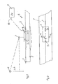
- FIG. 1 shows a schematic diagram of a representation with which the inventive method is to be illustrated.
- Shown are rails 1, which are laid in this example on longitudinally spaced reinforced concrete beams 2.
- the reinforced concrete beams 2, respectively the rails 1, are laid parallel to each other running with a large track width and serve to receive an only indicated conveyor 3.
- the conveyor 3 may for example be a port handling facility, such as a crane or the like, and has a correspondingly high service weight, so that already high forces are introduced into the rails 1 in the unloaded state. These forces increase in the course of loading or unloading of transport containers, such as ships, railway carriages or the like.
- the conveyor 3 has wheels 4, which rest on the respective rail 1.
- Reinforced concrete beams 2 laid in particular in the area of port facilities tend to lower under heavy weight loads.
- the rail measuring vehicle 5 has rollers 5 ', which roll on the respective rail 1.
- an electrical Drive over which the rail measuring vehicle in the longitudinal direction of the respective rail, for example, remotely controlled, can be driven.
- FIG. 2 shows a schematic diagram of the measuring system for illustrating the method according to the invention in side view.
- the rail measuring vehicle 5 has a reflector 7 (measuring aid), which is aligned towards the tachymeter 6.
- the rail measuring vehicle is connected to a data processing system 9, which also has an antenna 10.
- the reinforced concrete beam 2 on which the rail 1 is mounted. Dashed indicates a lowered portion 11 of the reinforced concrete beam 2.
- a corresponding measurement process instead, by which a height difference .DELTA.h can be determined.
- This determined measured value is transmitted to the data processing system 9 and the remote area 11 is documented.
- either the rail 1 with plates can now be lined or raised at greater subsidence phenomena 11 of the reinforced concrete beams 2 by relining.
- FIG. 3 shows the rail measuring vehicle 5 in plan view. Visible is the rail 1 and the rail 1 receiving reinforced concrete beam 2. Only indicated are the measuring aids (reflector 7) and other measuring means 12,13,14 and the antenna. 8
- the measuring means 12 designed as a sensor measures the inclination transverse to the rail 1.
- the measuring means 13 is likewise formed by a sensor and measures the inclination in the rail longitudinal direction and serves as a supplement to the tachymeter measurement, as described in US Pat FIG. 1 and 2 is addressed.
- Further measuring means 14 in the form of sensors measure, for example, the rail height, ie the distance of the rail 1 to the reinforced concrete beam 2. Die individual readings, as in FIG. 2 indicated, transmitted via the antenna 8 to the data processing system 9 and documented.
Landscapes
- Engineering & Computer Science (AREA)
- Physics & Mathematics (AREA)
- General Physics & Mathematics (AREA)
- Radar, Positioning & Navigation (AREA)
- Remote Sensing (AREA)
- Architecture (AREA)
- Civil Engineering (AREA)
- Structural Engineering (AREA)
- Length Measuring Devices With Unspecified Measuring Means (AREA)
- Analysing Materials By The Use Of Radiation (AREA)
- Machines For Laying And Maintaining Railways (AREA)
Abstract
Description
Die Erfindung betrifft ein Verfahren zur geodätischen Überwachung von Schienen, auf denen sich verfahrbare Fördergeräte bewegen.The invention relates to a method for geodetic monitoring of rails on which movable conveyors move.
Die
Ziel des Erfindungsgegenstandes ist es, ein alternatives Messverfahren bereit zu stellen, das einfacher im Aufbau ist, auch schnellere Vergleichsmessungen erlaubt und die Messergebnisse im Raumbezug liefert.The aim of the subject invention is to provide an alternative measurement method that is simpler in construction, also allows faster comparative measurements and provides the measurement results in spatial reference.
Des Weiteren soll ein Schienenmessfahrzeug bereitgestellt werden, das zur Überprüfung einzelner Schienen vorgesehen ist und beliebige Parameter der jeweiligen Schienen vermessen kann.Furthermore, a rail measuring vehicle is to be provided, which is provided for checking individual rails and can measure any parameters of the respective rails.
Dieses Ziel wird erreicht durch ein Verfahren zur geodätischen Überwachung von für Fördergeräte vorgesehene Schienen, indem zumindest im Bereich eines Schienenendes ein Tachymeter mit Raumbezug stationiert wird, auf der jeweils zu überprüfenden Schiene ein Schienenmessfahrzeug aufgesetzt wird, das zur Messung eines unbelasteten Zustands der Schiene die jeweilige Schiene allein befährt und zur Messung eines belasteten Zustands der Schiene mit der gleichen Geschwindigkeit, wie das Fördergerät angetrieben wird, wobei die Aufnahme der Messpunkte während der Messung im be- und/oder unbelasteten Zustand der jeweiligen Schiene kontinuierlich erfolgt.This object is achieved by a method for geodetic monitoring of rails provided for conveyors, by at least in the region of a rail end stationed a tachymeter with spatial reference, on the rail to be tested a rail measuring vehicle is placed, the measuring of an unloaded state of the rail the respective Track alone and for measuring a loaded state of the rail at the same speed as the conveyor is driven, wherein the recording of the measuring points during the measurement in the loaded and / or unloaded state of the respective rail is continuous.
Vorteilhafte Weiterbildungen des erfindungsgemäßen Verfahrens sind den zugehörigen verfahrensgemäßen Unteransprüchen zu entnehmen.Advantageous developments of the method according to the invention can be found in the associated subclaims.
Dieses Ziel wird auch erreicht durch einen Schienenmessfahrzeug, beinhaltend mindestens ein auf der jeweiligen zu vermessenden Schiene aufsetzbares Laufrad, das in Wirkverbindung mit einer Messhilfsmittel/Messmittel aufnehmenden Plattform steht.This object is also achieved by a rail measuring vehicle, comprising at least one impeller which can be placed on the respective rail to be measured and which is in operative connection with a measuring aid / measuring means receiving platform.
Vorteilhafte Weiterbildungen des erfindungsgemäßen Schienenmessfahrzeuges sind den zugehörigen gegenständlichen Unteransprüchen zu entnehmen.Advantageous developments of the rail measuring vehicle according to the invention can be found in the associated subject subclaims.
Im Folgenden wird als Beispiel für ein Messsystem für Schienen ein Stahlbetonbalken als Aufnahmeelement für eine einzelne Schiene herangezogen. Ebenso gut könnte es sich auch um Schwellen, o.ä. handeln.In the following, as an example of a rail measuring system, a reinforced concrete beam is used as a single rail receiving element. Equally well it could also be thresholds, or similar. act.
Insbesondere im Bereich von Hafenanlagen ist der die Stahlbetonbalken aufnehmende Untergrund eher schlecht, so dass aufgrund der großen Belastung durch die auf den mit großer Spurbreite vorgesehenen Schienen verfahrbaren Fördergeräten (Krane oder dergleichen) sich hohe ermüdungswirksame Beanspruchungen für den jeweiligen Stahlbetonbalken ergeben. Mit Hilfe des erfindungsgemäßen geodätischen Überwachungsverfahrens werden das Verhalten der auf den Stahlbetonbalken aufgebrachten Schienen überwacht und Rückschlüsse auf mögliche Setzungs- und Verformungserscheinungen gezogen.Particularly in the area of port facilities, the substructure receiving the reinforced concrete beams is rather poor, so that due to the great load on the conveyors (cranes or the like) that can be moved on the rails provided with a large track width, high fatigue loads are produced for the respective reinforced concrete beam. With the help of the geodetic monitoring method according to the invention, the behavior monitored on the reinforced concrete beams rails and draw conclusions on possible settling and deformation phenomena.
Zur Überprüfung der in vorangegangenen statischen Berechnungen getroffenen Annahmen ist es notwendig, die Auswirkungen von Beanspruchungen aus äußerer Last und Zwang (Temperatur) zu verifizieren. Werden signifikante Setzungen des Stahlbetonbalkens oder Verformungen der jeweiligen Schiene durch das Monitoring festgestellt, können diese durch Einsatz von Ausgleichsplatten bzw. lokalem Anheben des Stahlbetonbalkens ausgeglichen werden. Beim Einsatz von quer zu den Schienen verlegten Schwellen als Schienenaufnahmesystem erfolgt dies durch Stopfen oder ähnlich geeignete Maßnahmen.To verify the assumptions made in previous static calculations, it is necessary to verify the effects of external load and force (temperature) stresses. If significant settlements of the reinforced concrete beam or deformations of the respective rail are detected by the monitoring, these can be compensated by using compensating plates or locally lifting the reinforced concrete beam. When using thresholds laid transversely to the rails as a rail mounting system, this is done by plugging or similar suitable measures.
Zur Überprüfung der Spurweiten und Höhen werden die Schienen einzeln vermessen. Jede Schiene kann bis zu 400 m lang sein. Bedarfsweise können auch längere Schienen auf entsprechende Balken/Schwellen eingesetzt werden. Um lokale Mulden zu erkennen und zu dokumentieren, ist auch eine Vermessung der jeweiligen Schiene im belasteten Zustand vorgesehen.To check the gauges and heights, the rails are measured individually. Each rail can be up to 400 m long. If necessary, longer rails can be used on corresponding beams / sleepers. In order to detect and document local depressions, a measurement of the respective rail in the loaded state is also provided.
Die Vermessung erfolgt mit einem geodätischen Tachymeter höchster Genauigkeit. Die Signalisierung der auszumessenden Punkte erfolgt mittels eines kleinen selbst fahrenden und bedarfsweise ferngesteuerten Schienenmessfahrzeugs sowohl im be- als auch im unbelasteten Zustand der Schienen.The measurement is carried out with a geodetic tachymeter of highest accuracy. The signaling of the points to be measured by means of a small self-propelled and, if necessary, remotely controlled rail measuring vehicle both in loading as well as in the unloaded condition of the rails.
Sollten bei den Messungen im belasteten Zustand signifikante Setzungen registriert werden, sind gegebenenfalls weitere Vermessungen bei stillstehendem Fördergerät über den Setzungsmulden hilfreich.If significant settlements are recorded during the measurements in the loaded condition, further surveys with a stationary conveyor over the settlement wells may be helpful.
Jede Schiene wird vorzugsweise in einem vermessungstechnischen Arbeitsgang von der beiden Seiten erfasst. Die Vermessung der einzelnen Schienen erfolgt von den Stirnseiten der Kranbahn. Die Messung ist an eine Datenverarbeitungsanlage lage- und höhenmäßig angebunden und damit unabhängig von lokalen Setzungen.Each rail is preferably captured in a surveying operation from both sides. The measurement of the individual rails takes place from the front sides of the crane runway. The measurement is connected to a data processing system in terms of position and height and thus independent of local subsidence.
Spurweiten können damit direkt abgeleitet und die Messungen über einen längeren Zeitraum miteinander verglichen werden.Gauges can thus be derived directly and the measurements over a longer period compared.
Die Aufnahme der Messpunkte erfolgt während der Messung im be- und im unbelasteten Zustand, im so genannten Trackingmodus, das heißt, dass das Ziel kontinuierlich verfolgt und die Position registriert wird.The recording of the measuring points takes place during the measurement in the unloaded state and in the so-called tracking mode, that is, the target is continuously tracked and the position is registered.
Die Erfassungsgeschwindigkeit des Schienenmessfahrzeuges bestimmt den Punktabstand. Bei einer Zeitspanne zwischen der Erfassung zweier Messpunkte von 0,3 bis 0,5 Sekunden, ergibt sich ein Punktabstand von 0,3 bis 0,5 m in Schienenlängsrichtung bei einer Fahrgeschwindigkeit von 1 m/s.The detection speed of the rail measuring vehicle determines the point distance. At a time interval between the detection of two measuring points of 0.3 to 0.5 seconds, there is a point distance of 0.3 to 0.5 m in the rail longitudinal direction at a travel speed of 1 m / s.
Für die Messung des unbelasteten Zustandes fährt das Schienenmessfahrzeug beispielsweise ferngesteuert über die jeweilige Schiene, während das Fördergerät in einer Warteposition parkt.For the measurement of the unloaded state, the rail measuring vehicle, for example, runs remotely over the respective rail while the conveyor is parked in a waiting position.
Das eingesetzte Schienenmessfahrzeug fährt bei der Messung im belasteten Zustand in kurzer Entfernung zum Fahrwerk des Fördergerätes (beispielsweise an den Kran oder dessen Fahrwerk gekoppelt) und damit mit gleicher Geschwindigkeit des Fördergerätes und ermöglicht so die Aufnahme der jeweiligen Schiene. Zur Genauigkeitssteigerung und zur Ausschaltung von Zielachs- und Kippachsfehlern ist für eine Zustandsmessung eine Vor- und Rückfahrt des Schienenfahrzeuges bei einer Beobachtung in I. und II. Fernrohrlage des Tachymeters sinnvoll.The used rail measuring vehicle moves when measuring in the loaded state at a short distance to the chassis of the conveyor (for example, coupled to the crane or its chassis) and thus at the same speed of the conveyor and thus allows the inclusion of the respective rail. To increase the accuracy and to eliminate Zielachs- and Kippachsfehlern a forward and backward travel of the rail vehicle in a observation in I. and II. Telescope position of the tachymeter makes sense for a condition measurement.
Für die Vermessung kommt ein Präzisionstachymeter mit einer inneren Winkelmessgenauigkeit von mindestens 0,15 mgon und automatischer Zielverfolgung zum Einsatz.For the measurement, a precision total station with an internal angle measurement accuracy of at least 0.15 mg and automatic target tracking is used.
Der Transport des Reflektors (Messhilfsmittel) erfolgt durch das Schienenmessfahrzeug, das folgende Eigenschaften aufweist:
- selbstfahrend, d. h. ferngesteuert
- leicht
- kompakt
- wettergeschützt (Feuchtigkeit, Kälte, Wärme, Staub)
- stabil
- lange Batteriedauer
- Möglichkeit zur Kopplung des Schienenmessfahrzeuges an das Fördergerät
- durch eine Markierung an dem Schienenmessfahrzeug wird sichergestellt, dass das Schienenmessfahrzeug immer an der gleichen Schienenflanke anliegt.
- self-propelled, ie remotely controlled
- light
- compact
- weatherproof (humidity, cold, heat, dust)
- stable
- long battery life
- Possibility of coupling the rail measuring vehicle to the conveyor
- A marking on the rail measuring vehicle ensures that the rail measuring vehicle always bears against the same rail flank.
Hohe Anforderungen werden an die Genauigkeit in Quer-/Längsrichtung und Höhe der jeweiligen Schiene gestellt. Zur Erreichung einer ausreichenden Genauigkeit kann das Schienenmessfahrzeug mit einer Geschwindigkeit von bis zu 1 m/s verfahren werden.High demands are placed on the accuracy in the transverse / longitudinal direction and height of the respective rail. To achieve sufficient accuracy, the rail measuring vehicle can be moved at a speed of up to 1 m / s.
Mit dem Erfindungsgegenstand sind folgende Vorteile verbunden:
- Minimierung der gesamten Messzeit
- Messung der jeweiligen Schiene in zwei Belastungszuständen
- Ausschaltung von Gerätefehlern (Zielachs- und Kippachsfehler)
- Einsatz von Standardvermessungsgeräten (Tachymeter höchster Genauigkeit).
- Minimization of the entire measuring time
- Measurement of the respective rail in two loading conditions
- Elimination of device errors (target axis and tilt axis error)
- Use of standard surveying equipment (highest accuracy tachymeter).
Der Erfindungsgegenstand ist anhand eines Ausführungsbeispiels dargestellt und wird wie folgt beschrieben. Es zeigen:
- Figur 1
- Prinzipskizze zur Veranschaulichung des erfindungsgemäßen Verfahrens in der Draufsicht;
Figur 2- Prinzipskizze des Schienenmessfahrzeugs in Wirkverbindung mit einem Tachymeter und einer Datenverarbeitungsanlage;
- Figur 3
- Draufsicht auf das Schienenmessfahrzeug mit angedeuteten Messhilfsmitteln/Messmitteln.
- FIG. 1
- Schematic diagram illustrating the process of the invention in plan view;
- FIG. 2
- Schematic diagram of the rail measuring vehicle in operative connection with a total station and a data processing system;
- FIG. 3
- Top view of the rail measuring vehicle with indicated measuring aids / measuring means.
Das als Sensor ausgebildete Messmittel 12 misst die Neigung quer zur Schiene 1. Das Messmittel 13 ist ebenfalls durch einen Sensor gebildet und misst die Neigung in Schienenlängsrichtung sowie dient als Ergänzung der Tachymetermessung, wie sie in
Weitere Messmittel 14 in Form von Sensoren messen zum Beispiel die Schienenhöhe, d.h. den Abstand der Schiene 1 zum Stahlbetonbalken 2. Die einzelnen Messwerte werden, wie in
- 11
- Schienerail
- 22
- StahlbetonbalkenReinforced concrete beam
- 33
- Fördergerätconveyor
- 44
- LaufradWheel
- 55
- SchienenmessfahrzeugRail measuring vehicle
- 5'5 '
- Laufrollecaster
- 66
- Tachymetertachymeter
- 77
- Reflektor (Messhilfsmittel)Reflector (measuring aids)
- 88th
- Antenneantenna
- 99
- DatenverarbeitungsanlageData processing system
- 1010
- Antenneantenna
- 1111
- abgesetzter Abschnittstepped section
- 1212
- Sensor (Messmittel)Sensor (measuring device)
- 1313
- Sensor (Messmittel)Sensor (measuring device)
- 1414
- Sensor (Messmittel)Sensor (measuring device)
Claims (10)
Applications Claiming Priority (1)
| Application Number | Priority Date | Filing Date | Title |
|---|---|---|---|
| DE200710033185 DE102007033185A1 (en) | 2007-07-17 | 2007-07-17 | Method for geodetic monitoring of rails |
Publications (2)
| Publication Number | Publication Date |
|---|---|
| EP2017574A2 true EP2017574A2 (en) | 2009-01-21 |
| EP2017574A3 EP2017574A3 (en) | 2010-03-31 |
Family
ID=39803108
Family Applications (1)
| Application Number | Title | Priority Date | Filing Date |
|---|---|---|---|
| EP08012279A Withdrawn EP2017574A3 (en) | 2007-07-17 | 2008-07-08 | Method for geodesic monitoring of rails |
Country Status (2)
| Country | Link |
|---|---|
| EP (1) | EP2017574A3 (en) |
| DE (1) | DE102007033185A1 (en) |
Cited By (5)
| Publication number | Priority date | Publication date | Assignee | Title |
|---|---|---|---|---|
| US9784579B2 (en) | 2009-11-10 | 2017-10-10 | Konecranes Global Corporation | Runway measurement system and method |
| CN112113528A (en) * | 2020-09-21 | 2020-12-22 | 河钢股份有限公司承德分公司 | Automatic rail wear detection marking vehicle and use method thereof |
| CN112762891A (en) * | 2020-12-23 | 2021-05-07 | 济南轨道交通集团有限公司 | Track heave monitoring device and method based on distributed measurement |
| CN113049157A (en) * | 2021-03-08 | 2021-06-29 | 石家庄铁道大学 | Steel rail neutral shaft and wheel rail force testing position positioning device |
| CN113049156A (en) * | 2021-03-08 | 2021-06-29 | 石家庄铁道大学 | Process for efficiently testing force positions of neutral axis and wheel rail of steel rail |
Families Citing this family (1)
| Publication number | Priority date | Publication date | Assignee | Title |
|---|---|---|---|---|
| DE102015103054B3 (en) * | 2015-03-03 | 2016-06-16 | Dr. Hesse und Partner Ingenieure | System for kinematic rail measurement |
Citations (6)
| Publication number | Priority date | Publication date | Assignee | Title |
|---|---|---|---|---|
| DD212931A1 (en) | 1982-12-30 | 1984-08-29 | Bauakademie Ddr | MEASURING ARRANGEMENT FOR MONITORING RAIL TRACKS |
| DE3444723A1 (en) * | 1984-12-07 | 1986-06-12 | Richard Gehrcke | Device for detecting the track geometry by means of a laser |
| DE3808972A1 (en) | 1988-03-17 | 1989-10-05 | Hipp Johann F | Device for continuous tracking and position measurement of an object |
| DE4219256A1 (en) * | 1991-06-17 | 1992-12-24 | Plasser Bahnbaumasch Franz | METHOD AND MACHINE FOR CORRECTING THE POSITION OF A TRACK ON A SUPPORTING LAYER |
| DE19747872C2 (en) | 1997-10-20 | 2000-01-05 | Mannesmann Ag | System for the measurement of rails, in particular rails for cranes, storage and retrieval machines, wheel blocks |
| DE68914828T3 (en) * | 1988-02-22 | 2001-02-15 | Matti Henttinen | DEVICE AND METHOD FOR DETERMINING THE LOCATION OF A RAIL. |
-
2007
- 2007-07-17 DE DE200710033185 patent/DE102007033185A1/en not_active Withdrawn
-
2008
- 2008-07-08 EP EP08012279A patent/EP2017574A3/en not_active Withdrawn
Patent Citations (6)
| Publication number | Priority date | Publication date | Assignee | Title |
|---|---|---|---|---|
| DD212931A1 (en) | 1982-12-30 | 1984-08-29 | Bauakademie Ddr | MEASURING ARRANGEMENT FOR MONITORING RAIL TRACKS |
| DE3444723A1 (en) * | 1984-12-07 | 1986-06-12 | Richard Gehrcke | Device for detecting the track geometry by means of a laser |
| DE68914828T3 (en) * | 1988-02-22 | 2001-02-15 | Matti Henttinen | DEVICE AND METHOD FOR DETERMINING THE LOCATION OF A RAIL. |
| DE3808972A1 (en) | 1988-03-17 | 1989-10-05 | Hipp Johann F | Device for continuous tracking and position measurement of an object |
| DE4219256A1 (en) * | 1991-06-17 | 1992-12-24 | Plasser Bahnbaumasch Franz | METHOD AND MACHINE FOR CORRECTING THE POSITION OF A TRACK ON A SUPPORTING LAYER |
| DE19747872C2 (en) | 1997-10-20 | 2000-01-05 | Mannesmann Ag | System for the measurement of rails, in particular rails for cranes, storage and retrieval machines, wheel blocks |
Cited By (7)
| Publication number | Priority date | Publication date | Assignee | Title |
|---|---|---|---|---|
| US9784579B2 (en) | 2009-11-10 | 2017-10-10 | Konecranes Global Corporation | Runway measurement system and method |
| CN112113528A (en) * | 2020-09-21 | 2020-12-22 | 河钢股份有限公司承德分公司 | Automatic rail wear detection marking vehicle and use method thereof |
| CN112762891A (en) * | 2020-12-23 | 2021-05-07 | 济南轨道交通集团有限公司 | Track heave monitoring device and method based on distributed measurement |
| CN113049157A (en) * | 2021-03-08 | 2021-06-29 | 石家庄铁道大学 | Steel rail neutral shaft and wheel rail force testing position positioning device |
| CN113049156A (en) * | 2021-03-08 | 2021-06-29 | 石家庄铁道大学 | Process for efficiently testing force positions of neutral axis and wheel rail of steel rail |
| CN113049157B (en) * | 2021-03-08 | 2022-05-03 | 石家庄铁道大学 | Steel rail neutral shaft and wheel rail force testing position positioning device |
| CN113049156B (en) * | 2021-03-08 | 2022-05-03 | 石家庄铁道大学 | Process for Efficient Testing of Rail Neutral Axis and Wheel-Rail Force Position |
Also Published As
| Publication number | Publication date |
|---|---|
| EP2017574A3 (en) | 2010-03-31 |
| DE102007033185A1 (en) | 2009-01-22 |
Similar Documents
| Publication | Publication Date | Title |
|---|---|---|
| EP0342655B1 (en) | Crane installation for a container | |
| EP2574587B1 (en) | Method for determining a target position for a container spreader and the container spreader | |
| EP3000762B1 (en) | Method for automatic, optical determination of a target position for a container lifting device | |
| DE69616041T2 (en) | METHOD AND DEVICE FOR THE CONTACT-FREE MEASUREMENT OF BENDING OF TRAILS OR RAILS | |
| EP2540651B1 (en) | Lift device, building and positioning device | |
| EP1283301B1 (en) | Machine and method for recognizing the sleeper positions in a track | |
| DE102020105804A1 (en) | System for inspecting a warehouse | |
| EP3369696B1 (en) | Industrial truck with sensor concept and industrial truck | |
| DE10323641A1 (en) | Movable sensor device on the load means of a forklift | |
| DE102010056584A1 (en) | Mobile work machine | |
| DE102018118703B4 (en) | crawler crane | |
| DE102008020170A1 (en) | Method and device for non-contact detection of the position of a height-adjustable lifting device of an industrial truck | |
| DE102008029205A1 (en) | Truck with optical lift height measurement | |
| EP1862593B2 (en) | GPS aided continuous route survey system with multi sensors | |
| DE112020000738T5 (en) | Carrier for a lifting device, the lifting device provided therewith and the associated working method | |
| DE102021130785A1 (en) | crane | |
| DE102007033185A1 (en) | Method for geodetic monitoring of rails | |
| DE102009025863A1 (en) | Leveling system for railway technology | |
| DE102009004854B4 (en) | Method and system for determining the position of an industrial truck | |
| DE102018210346B4 (en) | System and method for determining a lateral offset of a swap body in relation to a vehicle | |
| DE10161651B4 (en) | Method and arrangement for placing posts for guardrail systems in the ground | |
| EP0985630A1 (en) | Method and device for determining the load profile during loading and unloading of containers | |
| US7929118B2 (en) | Method for geodetic monitoring of rails | |
| DE102010054379A1 (en) | Method for determining transport state information of load carried by e.g. forklift truck, involves determining distance between transponder-receiver unit and transponder of transportation load, and transaction data | |
| DE19725315C2 (en) | Crane, especially steel mill crane |
Legal Events
| Date | Code | Title | Description |
|---|---|---|---|
| PUAI | Public reference made under article 153(3) epc to a published international application that has entered the european phase |
Free format text: ORIGINAL CODE: 0009012 |
|
| AK | Designated contracting states |
Kind code of ref document: A2 Designated state(s): AT BE BG CH CY CZ DE DK EE ES FI FR GB GR HR HU IE IS IT LI LT LU LV MC MT NL NO PL PT RO SE SI SK TR |
|
| AX | Request for extension of the european patent |
Extension state: AL BA MK RS |
|
| RAP1 | Party data changed (applicant data changed or rights of an application transferred) |
Owner name: THYSSENKRUPP GFT GLEISTECHNIK GMBH |
|
| PUAL | Search report despatched |
Free format text: ORIGINAL CODE: 0009013 |
|
| AK | Designated contracting states |
Kind code of ref document: A3 Designated state(s): AT BE BG CH CY CZ DE DK EE ES FI FR GB GR HR HU IE IS IT LI LT LU LV MC MT NL NO PL PT RO SE SI SK TR |
|
| AX | Request for extension of the european patent |
Extension state: AL BA MK RS |
|
| RIC1 | Information provided on ipc code assigned before grant |
Ipc: G01B 11/30 20060101ALI20100223BHEP Ipc: B61K 9/08 20060101ALI20100223BHEP Ipc: G01C 15/00 20060101AFI20081031BHEP |
|
| 17P | Request for examination filed |
Effective date: 20100421 |
|
| 17Q | First examination report despatched |
Effective date: 20100601 |
|
| AKX | Designation fees paid |
Designated state(s): AT BE BG CH CY CZ DE DK EE ES FI FR GB GR HR HU IE IS IT LI LT LU LV MC MT NL NO PL PT RO SE SI SK TR |
|
| STAA | Information on the status of an ep patent application or granted ep patent |
Free format text: STATUS: THE APPLICATION HAS BEEN WITHDRAWN |
|
| 18W | Application withdrawn |
Effective date: 20130318 |