EP2540531A2 - Trailer train - Google Patents
Trailer train Download PDFInfo
- Publication number
- EP2540531A2 EP2540531A2 EP12173468A EP12173468A EP2540531A2 EP 2540531 A2 EP2540531 A2 EP 2540531A2 EP 12173468 A EP12173468 A EP 12173468A EP 12173468 A EP12173468 A EP 12173468A EP 2540531 A2 EP2540531 A2 EP 2540531A2
- Authority
- EP
- European Patent Office
- Prior art keywords
- carriage
- base
- assembly according
- lever
- housing
- Prior art date
- Legal status (The legal status is an assumption and is not a legal conclusion. Google has not performed a legal analysis and makes no representation as to the accuracy of the status listed.)
- Granted
Links
Images

Classifications
-
- B—PERFORMING OPERATIONS; TRANSPORTING
- B62—LAND VEHICLES FOR TRAVELLING OTHERWISE THAN ON RAILS
- B62B—HAND-PROPELLED VEHICLES, e.g. HAND CARTS OR PERAMBULATORS; SLEDGES
- B62B5/00—Accessories or details specially adapted for hand carts
- B62B5/0026—Propulsion aids
- B62B5/0079—Towing by connecting to another vehicle
-
- B—PERFORMING OPERATIONS; TRANSPORTING
- B62—LAND VEHICLES FOR TRAVELLING OTHERWISE THAN ON RAILS
- B62B—HAND-PROPELLED VEHICLES, e.g. HAND CARTS OR PERAMBULATORS; SLEDGES
- B62B3/00—Hand carts having more than one axis carrying transport wheels; Steering devices therefor; Equipment therefor
- B62B3/02—Hand carts having more than one axis carrying transport wheels; Steering devices therefor; Equipment therefor involving parts being adjustable, collapsible, attachable, detachable or convertible
-
- B—PERFORMING OPERATIONS; TRANSPORTING
- B60—VEHICLES IN GENERAL
- B60D—VEHICLE CONNECTIONS
- B60D1/00—Traction couplings; Hitches; Draw-gear; Towing devices
- B60D1/24—Traction couplings; Hitches; Draw-gear; Towing devices characterised by arrangements for particular functions
- B60D1/26—Traction couplings; Hitches; Draw-gear; Towing devices characterised by arrangements for particular functions for remote control, e.g. for releasing
-
- B—PERFORMING OPERATIONS; TRANSPORTING
- B60—VEHICLES IN GENERAL
- B60D—VEHICLE CONNECTIONS
- B60D1/00—Traction couplings; Hitches; Draw-gear; Towing devices
- B60D1/48—Traction couplings; Hitches; Draw-gear; Towing devices characterised by the mounting
- B60D1/481—Traction couplings; Hitches; Draw-gear; Towing devices characterised by the mounting adapted for being mounted to the front and back of trailers, carts, trolleys, or the like to form a train
-
- B—PERFORMING OPERATIONS; TRANSPORTING
- B60—VEHICLES IN GENERAL
- B60D—VEHICLE CONNECTIONS
- B60D1/00—Traction couplings; Hitches; Draw-gear; Towing devices
- B60D2001/001—Traction couplings; Hitches; Draw-gear; Towing devices specially adapted for use on vehicles other than cars
- B60D2001/005—Traction couplings; Hitches; Draw-gear; Towing devices specially adapted for use on vehicles other than cars for carts, scooters, or the like
-
- B—PERFORMING OPERATIONS; TRANSPORTING
- B62—LAND VEHICLES FOR TRAVELLING OTHERWISE THAN ON RAILS
- B62B—HAND-PROPELLED VEHICLES, e.g. HAND CARTS OR PERAMBULATORS; SLEDGES
- B62B2202/00—Indexing codes relating to type or characteristics of transported articles
- B62B2202/90—Vehicles
-
- B—PERFORMING OPERATIONS; TRANSPORTING
- B62—LAND VEHICLES FOR TRAVELLING OTHERWISE THAN ON RAILS
- B62B—HAND-PROPELLED VEHICLES, e.g. HAND CARTS OR PERAMBULATORS; SLEDGES
- B62B2207/00—Joining hand-propelled vehicles or sledges together
-
- B—PERFORMING OPERATIONS; TRANSPORTING
- B62—LAND VEHICLES FOR TRAVELLING OTHERWISE THAN ON RAILS
- B62B—HAND-PROPELLED VEHICLES, e.g. HAND CARTS OR PERAMBULATORS; SLEDGES
- B62B5/00—Accessories or details specially adapted for hand carts
- B62B5/0006—Bumpers; Safety devices
Definitions
- the present invention relates to a handling assembly comprising a rolling base and a carriage adapted to receive a rolling base.
- the base generally remains the sole support for these parts and is therefore intended to park at the assembly station to which the parts are intended.
- the conveying of these rolling bases is done by train which circulates from one station to another to deliver the rolling bases.
- the bases are equipped with hitching means known in themselves to constitute directly a base train directly coupled to each other or to be inserted individually into a transport carriage, which simplifies the distribution plan bases to each post. Indeed, to avoid too many coupling and uncoupling, it is necessary, in the case of a base train, to provide the order in which the bases are delivered along the path traveled by the train. Then you have to plan a second route to take the empty bases.
- each base is uncoupled without affecting the continuity of the train and each unconnected full base can be immediately replaced by an empty base to be evacuated.
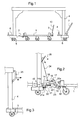
- the figure 1 schematically illustrates the state of the art.
- This figure shows a rolling base 1 equipped with hitching means here comprising at the rear, an axis 2 intended to enter the opening 3a of a tiller 3 tilting that any base has at the front.
- a cart 4 is here represented in the form of a vertical arch, provided with rolling means 5 and rear hitching means 6 and front 7 which are of the same type as those of the rolling base.
- This hoop can be in the shape of a horizontal C shape. Inside the hoop, the carriage has an axis 8 qi can be introduced into the ring 3a formed at the end of each drawbar 3 base. There are not shown safety means to ensure the coupling against unwanted detonations.
- the invention aims to overcome this disadvantage by means of a simple arrangement to facilitate this coupling.
- the operator can more easily maneuver the base relative to the carriage because the coupling point is located on the side of the end of the base opposite its drawbar which remains raised, which retains for the operator a larger space for maneuvering the base.
- the fixed means may be a vertical axis and the complementary means, a ring at the end of the tilting lever of the carriage but, preferably, the fixed means is a hook ball coupling while the complementary means comprises a housing for to style the sphere.
- At least one flexible element is suspended from a hoop of the carriage and has a length such that its lower end extends just above the loaded base, and / or the carriage has a towed front end provided with a drawbar equipped with coupling means and a towed rear end equipped with complementary coupling means which are arranged to cooperate with the coupling means of the drawbar of a second carriage or the drawbar of a second rolling base.
- the complementary means comprises a double hook having lower and upper ends which are arranged to cooperate with drawbars of different types and, according to a particular characteristic, the upper end of the double hook is provided with a coupling ball.
- the rolling base has a first end which comprises a drawbar 3 provided at its end with a housing-shaped coupling member 10 with a locking handle 11.
- the rolling base has a second end which is equipped with a hook 12 to ball or sphere 13.
- the carriage 4 comprises a towed end provided with a drawbar 7 having a free end provided with a box-shaped coupling member 70 with a locking handle 71 and an opposite end called traction provided with a hook 6 to ball.
- This arrangement allows the production of trolleys 4 by the cooperation of the housings 70 with the ball hooks 71 of the trolleys 4 (see FIG. figure 5 ).
- the housing 70 of the first carriage 4 of the train can be hooked to a hook of a towing vehicle while the ball hook 6 of the last carriage 4 of the train can be used to directly tow a rolling base 1 (the housing 10 drawbar 3 of said rolling base 1 then being engaged on the ball of the ball hook 6 of said last carriage 4).
- the provisions of the invention constitute a significant improvement in ergonomics for the operator (operator) responsible for handling empty or full wheel bases in a workshop for example mounting motor vehicles. Indeed, this operator is located at the rear of the base and the hitch is achieved by pushing the base which is easier than pulling. In addition, at the time of uncoupling, it is sufficient to push laterally the rear end of the base which will turn on itself with its diamond wheels and easily disengage the centering V 23. The operator can easily pass under the hoop that forms the carriage 4 to clear the base without difficulty or effort.
- the chains 30 have a length such that their lower end extends just above the loaded base.
- the chains 30 can be fixed under the bow, on a side of the bow or on both sides thereof.
- these chains are colored and / or contrasted to detach visually from their environment.
- the chains 30 are for example two-color.
- the carriage may comprise only one flexible element such as a curtain.
- the flexible element can equip any type of carriage having an arch independently of the coupling means thereof.
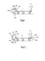
- the rolling base is identical to that previously described except that its second end is equipped with a double hook 112 in the form of a vertical bar having an upper end and a lower end, both referenced 150 on the figure 6 , to be engaged in a ring 151 of a drawbar 114.
- the upper end 150 is intended to be engaged in a drawbar recalled from a high position to a horizontal position by gravity as the drawbar 3 or by a spring such as lever 14.
- the lower end 150 is intended to be engaged in a drawbar biased from a low position to a horizontal position by a spring.
- drawbars are known in themselves and can be mounted on trolleys or other rolling bases.
- the rolling base is equipped with a double hook 112, 172 respectively at its first end and at its second end.
- the double hook 112 is identical to the double hook 112 described in connection with the figure 6 .
- the double hook 172 is identical to the double hook 112 except that its upper end is equipped with a ball 113 intended to cooperate with a housing 116 of a drawbar 114 which is biased from a high position to a position horizontal by gravity like the drawbar 3 or by a spring like the lever 14.
- the coupling means may have another structure than that described.
- trolleys 4 provided with a ball hook 6 that can cooperate with the casing 10 of the rolling bases for hanging a rolling base directly at the rear end of a train of trolleys (which makes it possible to do without a trolley), this arrangement is not obligatory.
- this possibility of attaching a base to the rear of a carriage is independent of the type of coupling means.
Landscapes
- Engineering & Computer Science (AREA)
- Chemical & Material Sciences (AREA)
- Combustion & Propulsion (AREA)
- Transportation (AREA)
- Mechanical Engineering (AREA)
- Handcart (AREA)
- Agricultural Machines (AREA)
Abstract
Description
La présente invention concerne un ensemble de manutention comprenant une base roulante et un chariot apte à recevoir une base roulante.The present invention relates to a handling assembly comprising a rolling base and a carriage adapted to receive a rolling base.
La manutention de pièces dans les ateliers de montage par exemple, s'opère au moyen de trains de bases roulantes sur le plateau desquelles les diverses pièces sont présentes. La base demeure en général le support unique pour ces pièces et donc est destiné à stationner au poste de montage auquel les pièces sont destinées. Le convoyage de ces bases roulantes se fait par train qui circule d'un poste à l'autre pour délivrer les bases roulantes. Les bases sont équipées de moyens d'attelage connus en eux-mêmes pour constituer directement un train de bases directement attelées les unes aux autres ou pour être insérées individuellement dans un chariot de transport, ce qui permet de simplifier le plan de distribution des bases à chaque poste. En effet, pour éviter les attelages et dételages trop nombreux, il faut, dans le cas d'un train de bases, prévoir l'ordre dans lequel les bases sont délivrées le long du trajet parcouru par le train. Il faut ensuite prévoir un deuxième parcours pour reprendre les bases vides. Dans le cas d'un train de chariots, chaque base est dételée sans nuire à la continuité du train et chaque base pleine dételée peut être immédiatement remplacée par une base vide à évacuer.The handling of parts in assembly workshops, for example, takes place by means of rolling base trains on the plate of which the various parts are present. The base generally remains the sole support for these parts and is therefore intended to park at the assembly station to which the parts are intended. The conveying of these rolling bases is done by train which circulates from one station to another to deliver the rolling bases. The bases are equipped with hitching means known in themselves to constitute directly a base train directly coupled to each other or to be inserted individually into a transport carriage, which simplifies the distribution plan bases to each post. Indeed, to avoid too many coupling and uncoupling, it is necessary, in the case of a base train, to provide the order in which the bases are delivered along the path traveled by the train. Then you have to plan a second route to take the empty bases. In the case of a train of carts, each base is uncoupled without affecting the continuity of the train and each unconnected full base can be immediately replaced by an empty base to be evacuated.
Il est ce pendant intéressant de disposer de bases qui puissent être employées soit directement soit dans des chariots.It is interesting to have bases that can be used either directly or in trolleys.
La
On a représenté sur cette figure une base roulante 1 équipée de moyens d'attelage ici comprenant à l'arrière, un axe 2 destiné à pénétrer dans l'ouverture 3a d'un timon 3 basculant que toute base possède à l'avant. Un chariot 4 est ici représenté sous la forme d'un arceau vertical, pourvu de moyens de roulement 5 et de moyens d'attelage arrière 6 et avant 7 qui sont du même type que ceux de la base roulante. Cet arceau peut être en forme de C horizontal. A l'intérieur de l'arceau, le chariot comporte un axe 8 qi peut être introduit dans l'anneau 3a ménagé à l'extrémité de chaque timon 3 de base. Il existe des moyens de sécurité non représentés pour assurer l'attelage contre les dételages intempestifs.This figure shows a
L'inconvénient important que l'on rencontre dans ce type de matériel réside dans la difficulté de réaliser l'attelage d'une base à l'intérieur du chariot. En effet, l'opérateur manie le chariot au moyen du timon 3 relevé pour l'introduire dans l'arceau puis ajuste la position relative de l'arceau et de la base, tant bien que mal, à l'étroit entre le timon et le chariot, pour que le rabattement du timon soit tel que son anneau tombe à l'aplomb de l'axe 8.The major disadvantage that we encounter in this type of equipment lies in the difficulty of achieving the coupling of a base inside the carriage. Indeed, the operator handles the truck by means of the
L'invention a pour but de pallier cet inconvénient au moyen d'une disposition simple pour faciliter cet attelage.The invention aims to overcome this disadvantage by means of a simple arrangement to facilitate this coupling.
C'est ainsi que l'invention a pour objet un ensemble de manutention comprenant:
- une base roulante équipée d'un timon basculant à l'une de ses extrémités et d'un moyen complémentaire fixe et court à son autre extrémité et
- un chariot dans lequel la base peut être attelée par l'une de ses extrémités,
- a rolling base equipped with a pivoting drawbar at one of its ends and a complementary means fixed and short at its other end and
- a carriage in which the base can be coupled by one of its ends,
Grâce à cette disposition, l'opérateur peut manoeuvrer plus aisément la base par rapport au chariot car le point d'attelage est situé du côté de l'extrémité de la base opposée à son timon qui demeure relevé, ce qui conserve pour l'opérateur un plus grand espace pour la manoeuvre de la base.With this arrangement, the operator can more easily maneuver the base relative to the carriage because the coupling point is located on the side of the end of the base opposite its drawbar which remains raised, which retains for the operator a larger space for maneuvering the base.
Le moyen fixe peut être un axe vertical et le moyen complémentaire, un anneau à l'extrémité du levier basculant du chariot mais, de manière préférée, le moyen fixe est un crochet à sphère d'attelage tandis que le moyen complémentaire comporte un boîtier pour coiffer la sphère.The fixed means may be a vertical axis and the complementary means, a ring at the end of the tilting lever of the carriage but, preferably, the fixed means is a hook ball coupling while the complementary means comprises a housing for to style the sphere.
De manière avantageuse, l'ensemble selon l'invention comporte des moyens qui permettent un attelage automatique de la base au chariot et un dételage simplifié. Ces moyens comportent notamment:
- une came montée coulissante sur le levier, escamotée par un poussoir dont l'extrémité est susceptible d'être déplacée par la sphère lors de la dernière phase de son approche sous le boîtier pour maintenir le levier porte boîtier en position haute, à l'encontre de l'effet d'un organe élastique de rappel,
- un V de guidage, situé sensiblement au niveau de la sphère quand le levier est dans sa position haute pour amener de manière certaine la sphère à désarmer la came et à être coiffée par le boîtier,
- un élément de transmission du mouvement d'une poignée de dételage qui agit sur le boîtier pour le déplacer à l'encontre de l'effet susdit de l'organe de rappel du levier en position basse, cet élément de transmission étant de préférence attelé au levier par l'intermédiaire d'un élément (poignée) de verrouillage du boîtier sur la sphère, connu en lui-même et équipé d'une pédale de mise en oeuvre par le pied de l'opérateur,
- un organe de rappel qui tend à replacer au dételage le poussoir dans sa position apte à être au contact avec la sphère et à maintenir la came dans son état non escamoté,
- un miroir disposé à l'aplomb des moyens d'attelage de la base au chariot.
- a cam mounted slidably on the lever, retracted by a pusher whose end can be moved by the sphere during the last phase of its approach under the housing to hold the door lever in the up position, against the effect of an elastic return member,
- a guide V, located substantially at the level of the sphere when the lever is in its high position to bring the sphere to disarm the cam and to be capped by the housing,
- an element for transmitting the movement of an uncoupling handle which acts on the housing to move it against the aforesaid effect of the lever return member in the low position, this transmission element being preferably coupled to the lever via an element (handle) locking the housing on the sphere, known in itself and equipped with a pedal implementation by the foot of the operator,
- a return member which tends to replace the uncoupling the pusher in its position adapted to be in contact with the sphere and to keep the cam in its non-retracted state,
- a mirror disposed above the coupling means of the base to the carriage.
De préférence également, au moins un élément souple est suspendu à un arceau du chariot et a une longueur telle que son extrémité inférieure s'étende juste au-dessus de la base chargée, et/ou le chariot comporte une extrémité avant tractée pourvue d'un timon équipé de moyens d'attelage et une extrémité arrière tractée équipée de moyens complémentaires d'attelage qui sont agencés pour coopérer avec les moyens d'attelage du timon d'un deuxième chariot ou du timon d'une deuxième base roulante.Also preferably, at least one flexible element is suspended from a hoop of the carriage and has a length such that its lower end extends just above the loaded base, and / or the carriage has a towed front end provided with a drawbar equipped with coupling means and a towed rear end equipped with complementary coupling means which are arranged to cooperate with the coupling means of the drawbar of a second carriage or the drawbar of a second rolling base.
Avantageusement, le moyen complémentaire comprend un crochet double ayant des extrémités inférieure et supérieure qui sont agencées pour coopérer avec des timons de types différents et, selon une caractéristique particulière, l'extrémité supérieure du crochet double est pourvue d'une boule d'attelage.Advantageously, the complementary means comprises a double hook having lower and upper ends which are arranged to cooperate with drawbars of different types and, according to a particular characteristic, the upper end of the double hook is provided with a coupling ball.
D'autres caractéristiques et avantages de l'invention ressortiront de la description donnée ci après à titre d'exemple.Other features and advantages of the invention will emerge from the description given below by way of example.
Il sera fait référence aux dessins annexés dans lesquels :
- la
figure 1 est, comme déjà dit, une illustration schématique d'un appareil selon l'état de la technique, - les
figures 2 et 3 illustrent par des vues partielles les dispositions particulières de l'invention aux extrémités longitudinales de l'ensemble du chariot, - la
figure 4 est une vue générale en élévation d'un chariot selon l'invention, - la
figure 5 est une vue analogue à lafigure 4 d'un train de chariots et bases roulantes conformes à l'invention, - _ la
figure 6 est une vue schématique en élévation d'une base roulante selon une variante de l'invention, - la
figure 7 est une vue analogue à lafigure 6 d'une base roulante selon une autre variante de l'invention.
- the
figure 1 is, as already said, a schematic illustration of a device according to the state of the art, - the
Figures 2 and 3 illustrate by partial views the particular provisions of the invention at the longitudinal ends of the carriage assembly, - the
figure 4 is a general elevational view of a carriage according to the invention, - the
figure 5 is a view similar to thefigure 4 of a train of trolleys and rolling bases conforming to the invention, - _ the
figure 6 is a schematic view in elevation of a rolling base according to a variant of the invention, - the
figure 7 is a view similar to thefigure 6 a rolling base according to another variant of the invention.
Aux
De manière connue, la base roulante a une première extrémité qui comporte un timon 3 pourvu à son extrémité d'un organe d'attelage en forme de boîtier 10 avec une poignée de verrouillage 11. La base roulante a une deuxième extrémité qui est équipée d'un crochet 12 à boule ou sphère 13.In known manner, the rolling base has a first end which comprises a
Le chariot 4 comporte une extrémité tractée pourvue d'un timon 7 ayant une extrémité libre pourvue d'un organe d'attelage en forme de boîtier 70 avec une poignée de verrouillage 71 et une extrémité opposée dite de traction pourvue d'un crochet 6 à boule. Cet agencement permet la réalisation de train de chariots 4 par la coopération des boîtiers 70 avec les crochets à boules 71 des chariots 4 (voir la
Selon l'invention, le chariot 4 comporte, à son extrémité tractée (
un levier 14 articulé en 15 autour d'un axe horizontal sur le chariot et porteur, à son extrémité libre d'un boîtier 16 du genre du boîtier 10 mais dans lequel l'organe de verrouillage a été légèrement modifié pour d'une part, permettre son actionnement par le pied d'un opérateur, grâce à une pédale 17 et, d'autre part, présenter une bielle de déverrouillage 18 manoeuvrable vers le haut.Le levier 14 est en permanence rappelé vers le bas par un organe de rappel (ressort) 14a.- une came 20 qui, dans un premier état (représenté), repose sur une
plaque 21 solidaire du chariot et dans un second état, après une translation vers la gauche de lafigure 2 , tombe dansun orifice 21a de cette plaque, sous l'effet de rappel du ressort 14a. Cette came 20 est en effet portée par le levier 14 et peut coulisser sous ce dernier. Un ressort 22 tend à tirer la came 20 vers la droite de la figure, dans une position qui ne lui permet pas de tomber dans l'orifice 21a. La came 20possède une extension 20a en direction de l'extrémité libre du levier 14 qui forme un poussoir à hauteur de la sphère 13 de sorte que, quand celle-ci est approchée de la came, elle la pousse sur une amplitude suffisante pour qu'elle tombe dans l'orifice 21 et que le levier 14 descende. Ainsi, le boîtier 16 vient-il coiffer la sphère 13 et l'opérateur, en manoeuvrant la pédale 17 avec le pied, verrouille l'attelage ainsi réalisé. - un V de centrage 23 sous le poussoir 20a de la came 20 pour guider de manière certaine la sphère dans la zone où elle viendra immanquablement au contact du poussoir et à l'aplomb précis du boîtier qui la coiffe.
un câble 24 qui court dans la structure du chariot depuis la bielle de déverrouillage 18 jusqu'à une poignée 25 de traction de ce câble suivant la flèche A (voirfigure 3 ) située à l'autre extrémité du chariot qui en est l'extrémité arrière. Ainsi quand l'opérateur souhaite dételer la base roulante, il tire sur la poignée 25, ce qui a pour effet de soulever la bielle 18. Le déverrouillage de l'attelage est obtenu et le boîtier peut être séparé de la sphère vers le haut, à l'encontre du rappel du ressort 14a. La came sort de l'orifice et sous l'action du ressort 22 coulisse vers la droite de la figure pourplacer le poussoir 20a dans sa position d'origine. Le câble 24 peut être remplacé par tout jeu de bielles et leviers adapté à transmettre le mouvement de la poignée 25 à la bielle 18.
- a
lever 14 articulated at 15 around a horizontal axis on the carriage and carrier, at its free end ahousing 16 of the type of thehousing 10 but in which the locking member has been slightly modified for the one hand, allow its actuation by the foot of an operator, with apedal 17 and on the other hand , have an unlockingrod 18 operable upwards. Thelever 14 is permanently biased downwards by a return member (spring) 14a. - a
cam 20 which, in a first state (shown), rests on aplate 21 secured to the carriage and in a second state, after a translation to the left of thefigure 2 falls into anorifice 21a of this plate, under the effect of thereturn spring 14a. Thiscam 20 is indeed carried by thelever 14 and can slide under the latter. Aspring 22 tends to pull thecam 20 to the right of the figure, in a position that does not allow it to fall into thehole 21a. Thecam 20 has anextension 20a towards the free end of thelever 14 which forms a pusher at the height of thesphere 13 so that when it is approaching the cam, it pushes it to a sufficient amplitude for it falls into thehole 21 and thelever 14 goes down. Thus, thehousing 16 comes to cap thesphere 13 and the operator, by operating the pedal 17 with the foot, locks the hitch thus produced. - a centering
V 23 under thepusher 20a of thecam 20 to guide the sphere in a certain way in the area where it will inevitably come into contact with the pusher and the precise plumb with the casing which caps it. - a
cable 24 running in the structure of the carriage from the unlockingrod 18 to ahandle 25 of this cable along the arrow A (seefigure 3 ) located at the other end of the carriage which is the rear end. Thus, when the operator wishes to detach the rolling base, he pulls on thehandle 25, which has the effect of lifting the connectingrod 18. The unlocking of the hitch is obtained and the housing can be separated from the sphere upwards, against the return of thespring 14a. The cam exits the orifice and under the action of thespring 22 slides to the right of the figure to place thepusher 20a in its original position. Thecable 24 can be replaced by any set of connecting rods and levers adapted to transmit the movement of thehandle 25 to the connectingrod 18.
On notera enfin la présence d'un miroir 26 en partie supérieure avant du chariot, à l'aplomb des moyens d'attelage, qui est tourné vers l'arrière pour permettre à l'opérateur situé aussi à l'arrière de l'ensemble, de voir et contrôler le déroulement des opérations d'attelage et de dételage.Note finally the presence of a
On comprend que les dispositions de l'invention constituent une amélioration importante de l'ergonomie pour l'opérateur (cariste) chargé de la manutention des bases roulantes vides ou pleines dans un atelier par exemple de montage de véhicules automobiles. En effet, cet opérateur est situé à l'arrière de la base et l'attelage est réalisé en poussant la base ce qui est plus aisé que de la tirer. De plus, au moment du dételage, il suffit de pousser latéralement l'extrémité arrière de la base qui tournera sur elle-même grâce à ses roues en losange et se désengagera aisément du V de centrage 23. L'opérateur peut aisément passer sous l'arceau que forme le chariot 4 pour dégager la base sans difficultés ni efforts.It is understood that the provisions of the invention constitute a significant improvement in ergonomics for the operator (operator) responsible for handling empty or full wheel bases in a workshop for example mounting motor vehicles. Indeed, this operator is located at the rear of the base and the hitch is achieved by pushing the base which is easier than pulling. In addition, at the time of uncoupling, it is sufficient to push laterally the rear end of the base which will turn on itself with its diamond wheels and easily disengage the centering
On notera sur la
Les chaînes 30 ont une longueur telle que leur extrémité inférieure s'étende juste au-dessus de la base chargée.The
Les chaînes 30 peuvent être fixées sous l'arceau, sur un flanc de l'arceau ou sur les deux flancs de celui-ci.The
De préférence, ces chaînes 30 sont colorées et/ou contrastées pour se détacher visuellement de leur environnement. Les chaînes 30 sont par exemple bicolores.Preferably, these chains are colored and / or contrasted to detach visually from their environment. The
Le chariot peut ne comprendre qu'un seul élément souple tel qu'un rideau. En outre, on notera que l'élément souple peut équiper tout type de chariot comportant un arceau indépendamment des moyens d'attelage de celui-ci.The carriage may comprise only one flexible element such as a curtain. In addition, it will be noted that the flexible element can equip any type of carriage having an arch independently of the coupling means thereof.
Dans la variante de la
On comprend que la base roulante ainsi équipée peut être reliée à des timons différents augmentant ses possibilités d'emploi.It is understood that the rolling base thus equipped can be connected to different shafts increasing its possibilities of use.
Dans la variante de la
Le crochet double 112 est identique au crochet double 112 décrit en relation avec la
Le crochet double 172 est identique au crochet double 112 sauf en ce que son extrémité supérieure est équipée d'une boule 113 destinée à coopérer avec un boîtier 116 d'un timon 114 rappelé d'une position haute vers une position horizontale par la gravité comme le timon 3 ou par un ressort comme le levier 14.The
Bien entendu, l'invention n'est pas limitée aux modes de réalisation décrits mais englobe toute variante couverte par la définition de l'invention figurant dans les revendications.Of course, the invention is not limited to the embodiments described but encompasses any variant covered by the definition of the invention in the claims.
Ainsi, les moyens d'attelage peuvent avoir une autre structure que celle décrite.Thus, the coupling means may have another structure than that described.
Par ailleurs, bien qu'il soit particulièrement intéressant d'avoir des chariots 4 pourvus d'un crochet à boule 6 pouvant coopérer avec le boîtier 10 des bases roulantes pour accrocher une base roulante directement à l'extrémité arrière d'un train de chariots (ce qui permet de se passer d'un chariot), cet agencement n'est pas obligatoire. En outre, cette possibilité d'accrochage d'une base à l'arrière d'un chariot est indépendante du type des moyens d'attelage.Moreover, although it is particularly interesting to have
Claims (13)
caractérisé en ce que les moyens d'attelage de la base dans le chariot sont constitués par le moyen fixe (12,13) susdit de la base et un moyen complémentaire (16) porté par l'extrémité d'un levier court (14) monté basculant (15) dans le chariot (4) entre une position haute de libération du moyen fixe et une position basse dans laquelle le moyen fixe (12,1) coopère avec le moyen complémentaire (16) à l'attelage de la base au chariot.
characterized in that the coupling means of the base in the carriage are constituted by the fixed means (12,13) above the base and a complementary means (16) carried by the end of a short lever (14). tilted mount (15) in the carriage (4) between a high position of release of the fixed means and a low position in which the fixed means (12,1) cooperates with the complementary means (16) to the hitch of the base at carriage.
Priority Applications (1)
| Application Number | Priority Date | Filing Date | Title |
|---|---|---|---|
| EP12173468.5A EP2540531B1 (en) | 2011-06-27 | 2012-06-25 | Trailer train |
Applications Claiming Priority (4)
| Application Number | Priority Date | Filing Date | Title |
|---|---|---|---|
| FR1155709A FR2976893B1 (en) | 2011-06-27 | 2011-06-27 | ROLLING BASE AND WORKSHOP CART |
| FR1158884 | 2011-09-30 | ||
| FR1253022 | 2012-04-02 | ||
| EP12173468.5A EP2540531B1 (en) | 2011-06-27 | 2012-06-25 | Trailer train |
Publications (3)
| Publication Number | Publication Date |
|---|---|
| EP2540531A2 true EP2540531A2 (en) | 2013-01-02 |
| EP2540531A3 EP2540531A3 (en) | 2013-09-04 |
| EP2540531B1 EP2540531B1 (en) | 2017-05-03 |
Family
ID=46275735
Family Applications (1)
| Application Number | Title | Priority Date | Filing Date |
|---|---|---|---|
| EP12173468.5A Active EP2540531B1 (en) | 2011-06-27 | 2012-06-25 | Trailer train |
Country Status (1)
| Country | Link |
|---|---|
| EP (1) | EP2540531B1 (en) |
Cited By (1)
| Publication number | Priority date | Publication date | Assignee | Title |
|---|---|---|---|---|
| US11536300B2 (en) * | 2016-02-15 | 2022-12-27 | Gea Food Solutions Bakel B.V. | Trolley detection and safety system |
Families Citing this family (6)
| Publication number | Priority date | Publication date | Assignee | Title |
|---|---|---|---|---|
| EP3379222B1 (en) | 2017-03-22 | 2020-12-30 | Methode Electronics Malta Ltd. | Magnetoelastic based sensor assembly |
| US11135882B2 (en) | 2018-02-27 | 2021-10-05 | Methode Electronics, Inc. | Towing systems and methods using magnetic field sensing |
| US11491832B2 (en) | 2018-02-27 | 2022-11-08 | Methode Electronics, Inc. | Towing systems and methods using magnetic field sensing |
| US10670479B2 (en) | 2018-02-27 | 2020-06-02 | Methode Electronics, Inc. | Towing systems and methods using magnetic field sensing |
| US11221262B2 (en) | 2018-02-27 | 2022-01-11 | Methode Electronics, Inc. | Towing systems and methods using magnetic field sensing |
| US11084342B2 (en) | 2018-02-27 | 2021-08-10 | Methode Electronics, Inc. | Towing systems and methods using magnetic field sensing |
Citations (3)
| Publication number | Priority date | Publication date | Assignee | Title |
|---|---|---|---|---|
| FR2843563A1 (en) | 2002-08-19 | 2004-02-20 | Coutier Ind | Transport and handling truck for loads in workshop has frame with tow coupling with ball and socket having catch |
| FR2886216A1 (en) | 2005-05-27 | 2006-12-01 | Coutier Ind Sarl Sarl | DEVICE FOR CONVEYING AN ERGONOMIC COUPLING MECHANISM |
| EP1743828A1 (en) | 2005-07-11 | 2007-01-17 | Fideve Groupe S.A.S. | Trailer for a transport train and transport train thus obtained |
-
2012
- 2012-06-25 EP EP12173468.5A patent/EP2540531B1/en active Active
Patent Citations (3)
| Publication number | Priority date | Publication date | Assignee | Title |
|---|---|---|---|---|
| FR2843563A1 (en) | 2002-08-19 | 2004-02-20 | Coutier Ind | Transport and handling truck for loads in workshop has frame with tow coupling with ball and socket having catch |
| FR2886216A1 (en) | 2005-05-27 | 2006-12-01 | Coutier Ind Sarl Sarl | DEVICE FOR CONVEYING AN ERGONOMIC COUPLING MECHANISM |
| EP1743828A1 (en) | 2005-07-11 | 2007-01-17 | Fideve Groupe S.A.S. | Trailer for a transport train and transport train thus obtained |
Cited By (1)
| Publication number | Priority date | Publication date | Assignee | Title |
|---|---|---|---|---|
| US11536300B2 (en) * | 2016-02-15 | 2022-12-27 | Gea Food Solutions Bakel B.V. | Trolley detection and safety system |
Also Published As
| Publication number | Publication date |
|---|---|
| EP2540531B1 (en) | 2017-05-03 |
| EP2540531A3 (en) | 2013-09-04 |
Similar Documents
| Publication | Publication Date | Title |
|---|---|---|
| EP2540531B1 (en) | Trailer train | |
| EP2540530B1 (en) | Trailer train | |
| EP0511922B1 (en) | Mowing machine with pivoting hitch structure | |
| FR2689090A1 (en) | Aircraft conveying vehicle on the ground. | |
| EP3307608B1 (en) | Trailer comprising an immobilisation means, vehicle controlling the reversible immobilisation and coupling of the trailer, and assembly formed by the coupling of such a trailer and such a vehicle | |
| EP0876929A1 (en) | Two point integral connecting device between trailer and vehicle provided with adjusting means | |
| FR2966120A1 (en) | Embarked device for blocking pivoting shaft of transport carriage in indexed lowered position to transport parts of automobile, has releasing unit releasing blocking of shaft in sliding of ground support position | |
| FR2918330A1 (en) | Transporting and/or handling trolley i.e. luggage, container or pallet carrying trailer, for use in e.g. airport, has support part, rod and traction cable for transporting braking units in disengagement position during withdrawal of element | |
| EP2505429B1 (en) | Method for adjusting the wheelbase of a wheel-mounted assembly comprising at least two handling devices for containers | |
| WO2006125895A1 (en) | Conveyor device with convenient coupling mechanism | |
| FR2709711A1 (en) | System for attaching a forklift to at least four attachment elements, cradle for attachment and corresponding forklift. | |
| EP0194285B1 (en) | Trailer particularly for camping | |
| FR2976893A1 (en) | Handling assembly for handling parts in assembly workshop of motor vehicle, has attachment unit formed by fixed unit and housing that is carried by end of lever mounted at axle to tilt between top release position of unit and low position | |
| EP2829501B1 (en) | Cantilever mounting device of a carriage on the rear of a carrier vehicle such as a truck | |
| FR2740735A1 (en) | Double attachment implement hitch for vehicle trailer | |
| EP2247489A1 (en) | Bearing for auxiliary caster of industrial truck and industrial truck provided with such bearing | |
| EP3156268B1 (en) | Trailer comprising a draw bar provided with means for quick installation onto a chassis of the trailer | |
| EP0283370B1 (en) | Support for a coupling mouth or coupling hook, with slides, for tractors | |
| EP3199434B1 (en) | Trailer provided with means for rapid installation of the drawbar on a frame | |
| FR2810618A1 (en) | Loading/unloading procedure for water scooters on towed trailer uses trolley for each loaded craft winched onto back of trailer | |
| FR2511965A1 (en) | LOCKING DEVICE FOR THE OPERATING ROD OF A SEMI-TRAILER HITCH | |
| EP2923863A1 (en) | Anti-theft device for coupling | |
| FR3037308A1 (en) | TRAILER FOR REACHING A TRACTOR VEHICLE AND ASSEMBLY COMPRISING SUCH A TRAILER | |
| FR3132682A1 (en) | Trailer coupling device of a vehicle | |
| FR2981607A1 (en) | DEVICE FOR FIXING AN ONBOARD OBJECT AT THE BACK OF A VEHICLE |
Legal Events
| Date | Code | Title | Description |
|---|---|---|---|
| PUAI | Public reference made under article 153(3) epc to a published international application that has entered the european phase |
Free format text: ORIGINAL CODE: 0009012 |
|
| AK | Designated contracting states |
Kind code of ref document: A2 Designated state(s): AL AT BE BG CH CY CZ DE DK EE ES FI FR GB GR HR HU IE IS IT LI LT LU LV MC MK MT NL NO PL PT RO RS SE SI SK SM TR |
|
| AX | Request for extension of the european patent |
Extension state: BA ME |
|
| TPAC | Observations filed by third parties |
Free format text: ORIGINAL CODE: EPIDOSNTIPA |
|
| PUAL | Search report despatched |
Free format text: ORIGINAL CODE: 0009013 |
|
| AK | Designated contracting states |
Kind code of ref document: A3 Designated state(s): AL AT BE BG CH CY CZ DE DK EE ES FI FR GB GR HR HU IE IS IT LI LT LU LV MC MK MT NL NO PL PT RO RS SE SI SK SM TR |
|
| AX | Request for extension of the european patent |
Extension state: BA ME |
|
| RIC1 | Information provided on ipc code assigned before grant |
Ipc: B60D 1/48 20060101ALI20130729BHEP Ipc: B60D 1/26 20060101AFI20130729BHEP |
|
| 17P | Request for examination filed |
Effective date: 20140228 |
|
| RBV | Designated contracting states (corrected) |
Designated state(s): AL AT BE BG CH CY CZ DE DK EE ES FI FR GB GR HR HU IE IS IT LI LT LU LV MC MK MT NL NO PL PT RO RS SE SI SK SM TR |
|
| REG | Reference to a national code |
Ref country code: DE Ref legal event code: R079 Ref document number: 602012031836 Country of ref document: DE Free format text: PREVIOUS MAIN CLASS: B60D0001000000 Ipc: B62B0005000000 |
|
| GRAP | Despatch of communication of intention to grant a patent |
Free format text: ORIGINAL CODE: EPIDOSNIGR1 |
|
| STAA | Information on the status of an ep patent application or granted ep patent |
Free format text: STATUS: GRANT OF PATENT IS INTENDED |
|
| RIC1 | Information provided on ipc code assigned before grant |
Ipc: B60D 1/00 20060101ALN20161107BHEP Ipc: B62B 5/00 20060101AFI20161107BHEP Ipc: B60D 1/48 20060101ALN20161107BHEP Ipc: B62B 3/02 20060101ALI20161107BHEP Ipc: B60D 1/26 20060101ALN20161107BHEP |
|
| INTG | Intention to grant announced |
Effective date: 20161125 |
|
| GRAS | Grant fee paid |
Free format text: ORIGINAL CODE: EPIDOSNIGR3 |
|
| GRAA | (expected) grant |
Free format text: ORIGINAL CODE: 0009210 |
|
| STAA | Information on the status of an ep patent application or granted ep patent |
Free format text: STATUS: THE PATENT HAS BEEN GRANTED |
|
| AK | Designated contracting states |
Kind code of ref document: B1 Designated state(s): AL AT BE BG CH CY CZ DE DK EE ES FI FR GB GR HR HU IE IS IT LI LT LU LV MC MK MT NL NO PL PT RO RS SE SI SK SM TR |
|
| REG | Reference to a national code |
Ref country code: GB Ref legal event code: FG4D Free format text: NOT ENGLISH |
|
| REG | Reference to a national code |
Ref country code: AT Ref legal event code: REF Ref document number: 889626 Country of ref document: AT Kind code of ref document: T Effective date: 20170515 Ref country code: CH Ref legal event code: EP |
|
| REG | Reference to a national code |
Ref country code: IE Ref legal event code: FG4D Free format text: LANGUAGE OF EP DOCUMENT: FRENCH |
|
| REG | Reference to a national code |
Ref country code: DE Ref legal event code: R096 Ref document number: 602012031836 Country of ref document: DE |
|
| REG | Reference to a national code |
Ref country code: FR Ref legal event code: PLFP Year of fee payment: 6 |
|
| REG | Reference to a national code |
Ref country code: NL Ref legal event code: MP Effective date: 20170503 |
|
| REG | Reference to a national code |
Ref country code: AT Ref legal event code: MK05 Ref document number: 889626 Country of ref document: AT Kind code of ref document: T Effective date: 20170503 |
|
| REG | Reference to a national code |
Ref country code: LT Ref legal event code: MG4D |
|
| PG25 | Lapsed in a contracting state [announced via postgrant information from national office to epo] |
Ref country code: LT Free format text: LAPSE BECAUSE OF FAILURE TO SUBMIT A TRANSLATION OF THE DESCRIPTION OR TO PAY THE FEE WITHIN THE PRESCRIBED TIME-LIMIT Effective date: 20170503 Ref country code: ES Free format text: LAPSE BECAUSE OF FAILURE TO SUBMIT A TRANSLATION OF THE DESCRIPTION OR TO PAY THE FEE WITHIN THE PRESCRIBED TIME-LIMIT Effective date: 20170503 Ref country code: GR Free format text: LAPSE BECAUSE OF FAILURE TO SUBMIT A TRANSLATION OF THE DESCRIPTION OR TO PAY THE FEE WITHIN THE PRESCRIBED TIME-LIMIT Effective date: 20170804 Ref country code: AT Free format text: LAPSE BECAUSE OF FAILURE TO SUBMIT A TRANSLATION OF THE DESCRIPTION OR TO PAY THE FEE WITHIN THE PRESCRIBED TIME-LIMIT Effective date: 20170503 Ref country code: FI Free format text: LAPSE BECAUSE OF FAILURE TO SUBMIT A TRANSLATION OF THE DESCRIPTION OR TO PAY THE FEE WITHIN THE PRESCRIBED TIME-LIMIT Effective date: 20170503 Ref country code: HR Free format text: LAPSE BECAUSE OF FAILURE TO SUBMIT A TRANSLATION OF THE DESCRIPTION OR TO PAY THE FEE WITHIN THE PRESCRIBED TIME-LIMIT Effective date: 20170503 Ref country code: NO Free format text: LAPSE BECAUSE OF FAILURE TO SUBMIT A TRANSLATION OF THE DESCRIPTION OR TO PAY THE FEE WITHIN THE PRESCRIBED TIME-LIMIT Effective date: 20170803 |
|
| PG25 | Lapsed in a contracting state [announced via postgrant information from national office to epo] |
Ref country code: IS Free format text: LAPSE BECAUSE OF FAILURE TO SUBMIT A TRANSLATION OF THE DESCRIPTION OR TO PAY THE FEE WITHIN THE PRESCRIBED TIME-LIMIT Effective date: 20170903 Ref country code: NL Free format text: LAPSE BECAUSE OF FAILURE TO SUBMIT A TRANSLATION OF THE DESCRIPTION OR TO PAY THE FEE WITHIN THE PRESCRIBED TIME-LIMIT Effective date: 20170503 Ref country code: LV Free format text: LAPSE BECAUSE OF FAILURE TO SUBMIT A TRANSLATION OF THE DESCRIPTION OR TO PAY THE FEE WITHIN THE PRESCRIBED TIME-LIMIT Effective date: 20170503 Ref country code: BG Free format text: LAPSE BECAUSE OF FAILURE TO SUBMIT A TRANSLATION OF THE DESCRIPTION OR TO PAY THE FEE WITHIN THE PRESCRIBED TIME-LIMIT Effective date: 20170803 Ref country code: RS Free format text: LAPSE BECAUSE OF FAILURE TO SUBMIT A TRANSLATION OF THE DESCRIPTION OR TO PAY THE FEE WITHIN THE PRESCRIBED TIME-LIMIT Effective date: 20170503 Ref country code: SE Free format text: LAPSE BECAUSE OF FAILURE TO SUBMIT A TRANSLATION OF THE DESCRIPTION OR TO PAY THE FEE WITHIN THE PRESCRIBED TIME-LIMIT Effective date: 20170503 Ref country code: PL Free format text: LAPSE BECAUSE OF FAILURE TO SUBMIT A TRANSLATION OF THE DESCRIPTION OR TO PAY THE FEE WITHIN THE PRESCRIBED TIME-LIMIT Effective date: 20170503 |
|
| PG25 | Lapsed in a contracting state [announced via postgrant information from national office to epo] |
Ref country code: CZ Free format text: LAPSE BECAUSE OF FAILURE TO SUBMIT A TRANSLATION OF THE DESCRIPTION OR TO PAY THE FEE WITHIN THE PRESCRIBED TIME-LIMIT Effective date: 20170503 Ref country code: RO Free format text: LAPSE BECAUSE OF FAILURE TO SUBMIT A TRANSLATION OF THE DESCRIPTION OR TO PAY THE FEE WITHIN THE PRESCRIBED TIME-LIMIT Effective date: 20170503 Ref country code: EE Free format text: LAPSE BECAUSE OF FAILURE TO SUBMIT A TRANSLATION OF THE DESCRIPTION OR TO PAY THE FEE WITHIN THE PRESCRIBED TIME-LIMIT Effective date: 20170503 Ref country code: DK Free format text: LAPSE BECAUSE OF FAILURE TO SUBMIT A TRANSLATION OF THE DESCRIPTION OR TO PAY THE FEE WITHIN THE PRESCRIBED TIME-LIMIT Effective date: 20170503 Ref country code: SK Free format text: LAPSE BECAUSE OF FAILURE TO SUBMIT A TRANSLATION OF THE DESCRIPTION OR TO PAY THE FEE WITHIN THE PRESCRIBED TIME-LIMIT Effective date: 20170503 |
|
| REG | Reference to a national code |
Ref country code: CH Ref legal event code: PL |
|
| REG | Reference to a national code |
Ref country code: DE Ref legal event code: R097 Ref document number: 602012031836 Country of ref document: DE |
|
| PG25 | Lapsed in a contracting state [announced via postgrant information from national office to epo] |
Ref country code: SM Free format text: LAPSE BECAUSE OF FAILURE TO SUBMIT A TRANSLATION OF THE DESCRIPTION OR TO PAY THE FEE WITHIN THE PRESCRIBED TIME-LIMIT Effective date: 20170503 Ref country code: IT Free format text: LAPSE BECAUSE OF FAILURE TO SUBMIT A TRANSLATION OF THE DESCRIPTION OR TO PAY THE FEE WITHIN THE PRESCRIBED TIME-LIMIT Effective date: 20170503 |
|
| PLBE | No opposition filed within time limit |
Free format text: ORIGINAL CODE: 0009261 |
|
| STAA | Information on the status of an ep patent application or granted ep patent |
Free format text: STATUS: NO OPPOSITION FILED WITHIN TIME LIMIT |
|
| REG | Reference to a national code |
Ref country code: IE Ref legal event code: MM4A |
|
| 26N | No opposition filed |
Effective date: 20180206 |
|
| PG25 | Lapsed in a contracting state [announced via postgrant information from national office to epo] |
Ref country code: LI Free format text: LAPSE BECAUSE OF NON-PAYMENT OF DUE FEES Effective date: 20170630 Ref country code: CH Free format text: LAPSE BECAUSE OF NON-PAYMENT OF DUE FEES Effective date: 20170630 Ref country code: LU Free format text: LAPSE BECAUSE OF NON-PAYMENT OF DUE FEES Effective date: 20170625 Ref country code: IE Free format text: LAPSE BECAUSE OF NON-PAYMENT OF DUE FEES Effective date: 20170625 |
|
| PG25 | Lapsed in a contracting state [announced via postgrant information from national office to epo] |
Ref country code: SI Free format text: LAPSE BECAUSE OF FAILURE TO SUBMIT A TRANSLATION OF THE DESCRIPTION OR TO PAY THE FEE WITHIN THE PRESCRIBED TIME-LIMIT Effective date: 20170503 |
|
| REG | Reference to a national code |
Ref country code: BE Ref legal event code: MM Effective date: 20170630 |
|
| REG | Reference to a national code |
Ref country code: FR Ref legal event code: PLFP Year of fee payment: 7 |
|
| PG25 | Lapsed in a contracting state [announced via postgrant information from national office to epo] |
Ref country code: BE Free format text: LAPSE BECAUSE OF NON-PAYMENT OF DUE FEES Effective date: 20170630 |
|
| PG25 | Lapsed in a contracting state [announced via postgrant information from national office to epo] |
Ref country code: MT Free format text: LAPSE BECAUSE OF FAILURE TO SUBMIT A TRANSLATION OF THE DESCRIPTION OR TO PAY THE FEE WITHIN THE PRESCRIBED TIME-LIMIT Effective date: 20170503 |
|
| PGFP | Annual fee paid to national office [announced via postgrant information from national office to epo] |
Ref country code: GB Payment date: 20180620 Year of fee payment: 7 |
|
| PG25 | Lapsed in a contracting state [announced via postgrant information from national office to epo] |
Ref country code: HU Free format text: LAPSE BECAUSE OF FAILURE TO SUBMIT A TRANSLATION OF THE DESCRIPTION OR TO PAY THE FEE WITHIN THE PRESCRIBED TIME-LIMIT; INVALID AB INITIO Effective date: 20120625 Ref country code: MC Free format text: LAPSE BECAUSE OF FAILURE TO SUBMIT A TRANSLATION OF THE DESCRIPTION OR TO PAY THE FEE WITHIN THE PRESCRIBED TIME-LIMIT Effective date: 20170503 |
|
| PG25 | Lapsed in a contracting state [announced via postgrant information from national office to epo] |
Ref country code: CY Free format text: LAPSE BECAUSE OF NON-PAYMENT OF DUE FEES Effective date: 20170503 |
|
| PG25 | Lapsed in a contracting state [announced via postgrant information from national office to epo] |
Ref country code: MK Free format text: LAPSE BECAUSE OF FAILURE TO SUBMIT A TRANSLATION OF THE DESCRIPTION OR TO PAY THE FEE WITHIN THE PRESCRIBED TIME-LIMIT Effective date: 20170503 |
|
| GBPC | Gb: european patent ceased through non-payment of renewal fee |
Effective date: 20190625 |
|
| PG25 | Lapsed in a contracting state [announced via postgrant information from national office to epo] |
Ref country code: TR Free format text: LAPSE BECAUSE OF FAILURE TO SUBMIT A TRANSLATION OF THE DESCRIPTION OR TO PAY THE FEE WITHIN THE PRESCRIBED TIME-LIMIT Effective date: 20170503 |
|
| PG25 | Lapsed in a contracting state [announced via postgrant information from national office to epo] |
Ref country code: GB Free format text: LAPSE BECAUSE OF NON-PAYMENT OF DUE FEES Effective date: 20190625 |
|
| PG25 | Lapsed in a contracting state [announced via postgrant information from national office to epo] |
Ref country code: PT Free format text: LAPSE BECAUSE OF FAILURE TO SUBMIT A TRANSLATION OF THE DESCRIPTION OR TO PAY THE FEE WITHIN THE PRESCRIBED TIME-LIMIT Effective date: 20170503 |
|
| PG25 | Lapsed in a contracting state [announced via postgrant information from national office to epo] |
Ref country code: AL Free format text: LAPSE BECAUSE OF FAILURE TO SUBMIT A TRANSLATION OF THE DESCRIPTION OR TO PAY THE FEE WITHIN THE PRESCRIBED TIME-LIMIT Effective date: 20170503 |
|
| PGFP | Annual fee paid to national office [announced via postgrant information from national office to epo] |
Ref country code: FR Payment date: 20230627 Year of fee payment: 12 Ref country code: DE Payment date: 20230620 Year of fee payment: 12 |