EP2540378B1 - Exhaust gas treatment system, and exhaust gas treatment method - Google Patents
Exhaust gas treatment system, and exhaust gas treatment method Download PDFInfo
- Publication number
- EP2540378B1 EP2540378B1 EP10846505.5A EP10846505A EP2540378B1 EP 2540378 B1 EP2540378 B1 EP 2540378B1 EP 10846505 A EP10846505 A EP 10846505A EP 2540378 B1 EP2540378 B1 EP 2540378B1
- Authority
- EP
- European Patent Office
- Prior art keywords
- water
- waste
- mercury
- flue gas
- desulfurizer
- Prior art date
- Legal status (The legal status is an assumption and is not a legal conclusion. Google has not performed a legal analysis and makes no representation as to the accuracy of the status listed.)
- Active
Links
- 238000000034 method Methods 0.000 title claims description 37
- 239000002351 wastewater Substances 0.000 claims description 208
- UGFAIRIUMAVXCW-UHFFFAOYSA-N Carbon monoxide Chemical compound [O+]#[C-] UGFAIRIUMAVXCW-UHFFFAOYSA-N 0.000 claims description 114
- 239000003546 flue gas Substances 0.000 claims description 114
- QSHDDOUJBYECFT-UHFFFAOYSA-N mercury Chemical compound [Hg] QSHDDOUJBYECFT-UHFFFAOYSA-N 0.000 claims description 112
- 229910052753 mercury Inorganic materials 0.000 claims description 111
- MWUXSHHQAYIFBG-UHFFFAOYSA-N nitrogen oxide Inorganic materials O=[N] MWUXSHHQAYIFBG-UHFFFAOYSA-N 0.000 claims description 111
- 239000007788 liquid Substances 0.000 claims description 67
- 238000004065 wastewater treatment Methods 0.000 claims description 63
- 238000003915 air pollution Methods 0.000 claims description 56
- -1 halogen ions Chemical class 0.000 claims description 32
- 229910052736 halogen Inorganic materials 0.000 claims description 27
- 239000000446 fuel Substances 0.000 claims description 26
- 239000002250 absorbent Substances 0.000 claims description 25
- 230000002745 absorbent Effects 0.000 claims description 25
- 239000007787 solid Substances 0.000 claims description 23
- 229910052815 sulfur oxide Inorganic materials 0.000 claims description 20
- 238000005345 coagulation Methods 0.000 claims description 18
- 230000015271 coagulation Effects 0.000 claims description 18
- XTQHKBHJIVJGKJ-UHFFFAOYSA-N sulfur monoxide Chemical class S=O XTQHKBHJIVJGKJ-UHFFFAOYSA-N 0.000 claims description 16
- 230000001590 oxidative effect Effects 0.000 claims description 12
- 239000012752 auxiliary agent Substances 0.000 claims description 11
- UCKMPCXJQFINFW-UHFFFAOYSA-N Sulphide Chemical compound [S-2] UCKMPCXJQFINFW-UHFFFAOYSA-N 0.000 claims description 8
- 230000003009 desulfurizing effect Effects 0.000 claims description 4
- XLYOFNOQVPJJNP-UHFFFAOYSA-N water Substances O XLYOFNOQVPJJNP-UHFFFAOYSA-N 0.000 description 59
- 229910052602 gypsum Inorganic materials 0.000 description 24
- 235000019738 Limestone Nutrition 0.000 description 19
- 239000010440 gypsum Substances 0.000 description 19
- 239000006028 limestone Substances 0.000 description 19
- 239000002002 slurry Substances 0.000 description 19
- 239000012716 precipitator Substances 0.000 description 10
- 239000007789 gas Substances 0.000 description 9
- 239000000126 substance Substances 0.000 description 9
- 238000011144 upstream manufacturing Methods 0.000 description 9
- RCTYPNKXASFOBE-UHFFFAOYSA-M chloromercury Chemical compound [Hg]Cl RCTYPNKXASFOBE-UHFFFAOYSA-M 0.000 description 8
- 238000009692 water atomization Methods 0.000 description 7
- 230000007423 decrease Effects 0.000 description 6
- 230000003247 decreasing effect Effects 0.000 description 6
- 239000000428 dust Substances 0.000 description 6
- 239000002245 particle Substances 0.000 description 6
- 239000012071 phase Substances 0.000 description 6
- 239000006228 supernatant Substances 0.000 description 6
- VEXZGXHMUGYJMC-UHFFFAOYSA-N Hydrochloric acid Chemical compound Cl VEXZGXHMUGYJMC-UHFFFAOYSA-N 0.000 description 5
- 238000002485 combustion reaction Methods 0.000 description 5
- 230000000694 effects Effects 0.000 description 5
- 238000011084 recovery Methods 0.000 description 5
- 239000003054 catalyst Substances 0.000 description 4
- 238000006243 chemical reaction Methods 0.000 description 4
- 239000000470 constituent Substances 0.000 description 4
- 238000010586 diagram Methods 0.000 description 4
- 238000001704 evaporation Methods 0.000 description 4
- 230000008020 evaporation Effects 0.000 description 4
- IXCSERBJSXMMFS-UHFFFAOYSA-N hydrogen chloride Substances Cl.Cl IXCSERBJSXMMFS-UHFFFAOYSA-N 0.000 description 4
- 229910000041 hydrogen chloride Inorganic materials 0.000 description 4
- 230000003647 oxidation Effects 0.000 description 4
- 238000007254 oxidation reaction Methods 0.000 description 4
- CPELXLSAUQHCOX-UHFFFAOYSA-M Bromide Chemical compound [Br-] CPELXLSAUQHCOX-UHFFFAOYSA-M 0.000 description 3
- VEXZGXHMUGYJMC-UHFFFAOYSA-M Chloride anion Chemical compound [Cl-] VEXZGXHMUGYJMC-UHFFFAOYSA-M 0.000 description 3
- KRHYYFGTRYWZRS-UHFFFAOYSA-M Fluoride anion Chemical compound [F-] KRHYYFGTRYWZRS-UHFFFAOYSA-M 0.000 description 3
- MHAJPDPJQMAIIY-UHFFFAOYSA-N Hydrogen peroxide Chemical compound OO MHAJPDPJQMAIIY-UHFFFAOYSA-N 0.000 description 3
- 239000000460 chlorine Substances 0.000 description 3
- 230000014509 gene expression Effects 0.000 description 3
- XMBWDFGMSWQBCA-UHFFFAOYSA-M iodide Chemical compound [I-] XMBWDFGMSWQBCA-UHFFFAOYSA-M 0.000 description 3
- 238000002156 mixing Methods 0.000 description 3
- 239000007800 oxidant agent Substances 0.000 description 3
- 238000000926 separation method Methods 0.000 description 3
- ZOXJGFHDIHLPTG-UHFFFAOYSA-N Boron Chemical compound [B] ZOXJGFHDIHLPTG-UHFFFAOYSA-N 0.000 description 2
- VTYYLEPIZMXCLO-UHFFFAOYSA-L Calcium carbonate Chemical compound [Ca+2].[O-]C([O-])=O VTYYLEPIZMXCLO-UHFFFAOYSA-L 0.000 description 2
- BUGBHKTXTAQXES-UHFFFAOYSA-N Selenium Chemical compound [Se] BUGBHKTXTAQXES-UHFFFAOYSA-N 0.000 description 2
- 229910052796 boron Inorganic materials 0.000 description 2
- 239000003638 chemical reducing agent Substances 0.000 description 2
- 229910052801 chlorine Inorganic materials 0.000 description 2
- 239000003245 coal Substances 0.000 description 2
- 239000000295 fuel oil Substances 0.000 description 2
- 238000009434 installation Methods 0.000 description 2
- 239000007791 liquid phase Substances 0.000 description 2
- 238000004519 manufacturing process Methods 0.000 description 2
- 239000012528 membrane Substances 0.000 description 2
- 239000013618 particulate matter Substances 0.000 description 2
- 229910052711 selenium Inorganic materials 0.000 description 2
- 239000011669 selenium Substances 0.000 description 2
- HYHCSLBZRBJJCH-UHFFFAOYSA-M sodium hydrosulfide Chemical compound [Na+].[SH-] HYHCSLBZRBJJCH-UHFFFAOYSA-M 0.000 description 2
- 229910052979 sodium sulfide Inorganic materials 0.000 description 2
- GRVFOGOEDUUMBP-UHFFFAOYSA-N sodium sulfide (anhydrous) Chemical compound [Na+].[Na+].[S-2] GRVFOGOEDUUMBP-UHFFFAOYSA-N 0.000 description 2
- 238000001179 sorption measurement Methods 0.000 description 2
- IJGRMHOSHXDMSA-UHFFFAOYSA-N Atomic nitrogen Chemical compound N#N IJGRMHOSHXDMSA-UHFFFAOYSA-N 0.000 description 1
- ZAMOUSCENKQFHK-UHFFFAOYSA-N Chlorine atom Chemical compound [Cl] ZAMOUSCENKQFHK-UHFFFAOYSA-N 0.000 description 1
- RWSOTUBLDIXVET-UHFFFAOYSA-N Dihydrogen sulfide Chemical compound S RWSOTUBLDIXVET-UHFFFAOYSA-N 0.000 description 1
- 229910016323 MxSy Inorganic materials 0.000 description 1
- CBENFWSGALASAD-UHFFFAOYSA-N Ozone Chemical compound [O-][O+]=O CBENFWSGALASAD-UHFFFAOYSA-N 0.000 description 1
- NINIDFKCEFEMDL-UHFFFAOYSA-N Sulfur Chemical compound [S] NINIDFKCEFEMDL-UHFFFAOYSA-N 0.000 description 1
- 239000003570 air Substances 0.000 description 1
- QVGXLLKOCUKJST-UHFFFAOYSA-N atomic oxygen Chemical compound [O] QVGXLLKOCUKJST-UHFFFAOYSA-N 0.000 description 1
- 229910000019 calcium carbonate Inorganic materials 0.000 description 1
- XTEGARKTQYYJKE-UHFFFAOYSA-N chloric acid Chemical class OCl(=O)=O XTEGARKTQYYJKE-UHFFFAOYSA-N 0.000 description 1
- 239000012320 chlorinating reagent Substances 0.000 description 1
- 239000000701 coagulant Substances 0.000 description 1
- 239000012141 concentrate Substances 0.000 description 1
- 238000007796 conventional method Methods 0.000 description 1
- 239000013078 crystal Substances 0.000 description 1
- 238000002425 crystallisation Methods 0.000 description 1
- 230000008025 crystallization Effects 0.000 description 1
- 229910001873 dinitrogen Inorganic materials 0.000 description 1
- 238000004821 distillation Methods 0.000 description 1
- 238000000909 electrodialysis Methods 0.000 description 1
- 238000001914 filtration Methods 0.000 description 1
- 239000012530 fluid Substances 0.000 description 1
- 229910001385 heavy metal Inorganic materials 0.000 description 1
- 239000003014 ion exchange membrane Substances 0.000 description 1
- 229910052742 iron Inorganic materials 0.000 description 1
- XEEYBQQBJWHFJM-UHFFFAOYSA-N iron Substances [Fe] XEEYBQQBJWHFJM-UHFFFAOYSA-N 0.000 description 1
- 150000002506 iron compounds Chemical class 0.000 description 1
- 229910052748 manganese Inorganic materials 0.000 description 1
- 239000011572 manganese Substances 0.000 description 1
- 150000002697 manganese compounds Chemical class 0.000 description 1
- 150000002730 mercury Chemical class 0.000 description 1
- 229910052751 metal Inorganic materials 0.000 description 1
- 239000002184 metal Substances 0.000 description 1
- 229910052976 metal sulfide Inorganic materials 0.000 description 1
- 229940008718 metallic mercury Drugs 0.000 description 1
- 230000005012 migration Effects 0.000 description 1
- 238000013508 migration Methods 0.000 description 1
- 239000003595 mist Substances 0.000 description 1
- 229910052760 oxygen Inorganic materials 0.000 description 1
- 239000001301 oxygen Substances 0.000 description 1
- 239000000843 powder Substances 0.000 description 1
- 238000010248 power generation Methods 0.000 description 1
- 238000001223 reverse osmosis Methods 0.000 description 1
- 230000000630 rising effect Effects 0.000 description 1
- 238000009287 sand filtration Methods 0.000 description 1
- 238000007711 solidification Methods 0.000 description 1
- 230000008023 solidification Effects 0.000 description 1
- 239000011593 sulfur Substances 0.000 description 1
- 229910052717 sulfur Inorganic materials 0.000 description 1
Images


Classifications
-
- C—CHEMISTRY; METALLURGY
- C02—TREATMENT OF WATER, WASTE WATER, SEWAGE, OR SLUDGE
- C02F—TREATMENT OF WATER, WASTE WATER, SEWAGE, OR SLUDGE
- C02F1/00—Treatment of water, waste water, or sewage
- C02F1/52—Treatment of water, waste water, or sewage by flocculation or precipitation of suspended impurities
- C02F1/5236—Treatment of water, waste water, or sewage by flocculation or precipitation of suspended impurities using inorganic agents
-
- B—PERFORMING OPERATIONS; TRANSPORTING
- B01—PHYSICAL OR CHEMICAL PROCESSES OR APPARATUS IN GENERAL
- B01D—SEPARATION
- B01D53/00—Separation of gases or vapours; Recovering vapours of volatile solvents from gases; Chemical or biological purification of waste gases, e.g. engine exhaust gases, smoke, fumes, flue gases, aerosols
- B01D53/14—Separation of gases or vapours; Recovering vapours of volatile solvents from gases; Chemical or biological purification of waste gases, e.g. engine exhaust gases, smoke, fumes, flue gases, aerosols by absorption
-
- B—PERFORMING OPERATIONS; TRANSPORTING
- B01—PHYSICAL OR CHEMICAL PROCESSES OR APPARATUS IN GENERAL
- B01D—SEPARATION
- B01D53/00—Separation of gases or vapours; Recovering vapours of volatile solvents from gases; Chemical or biological purification of waste gases, e.g. engine exhaust gases, smoke, fumes, flue gases, aerosols
- B01D53/34—Chemical or biological purification of waste gases
- B01D53/343—Heat recovery
-
- B—PERFORMING OPERATIONS; TRANSPORTING
- B01—PHYSICAL OR CHEMICAL PROCESSES OR APPARATUS IN GENERAL
- B01D—SEPARATION
- B01D53/00—Separation of gases or vapours; Recovering vapours of volatile solvents from gases; Chemical or biological purification of waste gases, e.g. engine exhaust gases, smoke, fumes, flue gases, aerosols
- B01D53/34—Chemical or biological purification of waste gases
- B01D53/38—Removing components of undefined structure
- B01D53/40—Acidic components
-
- B—PERFORMING OPERATIONS; TRANSPORTING
- B01—PHYSICAL OR CHEMICAL PROCESSES OR APPARATUS IN GENERAL
- B01D—SEPARATION
- B01D53/00—Separation of gases or vapours; Recovering vapours of volatile solvents from gases; Chemical or biological purification of waste gases, e.g. engine exhaust gases, smoke, fumes, flue gases, aerosols
- B01D53/34—Chemical or biological purification of waste gases
- B01D53/74—General processes for purification of waste gases; Apparatus or devices specially adapted therefor
- B01D53/75—Multi-step processes
-
- B—PERFORMING OPERATIONS; TRANSPORTING
- B01—PHYSICAL OR CHEMICAL PROCESSES OR APPARATUS IN GENERAL
- B01D—SEPARATION
- B01D53/00—Separation of gases or vapours; Recovering vapours of volatile solvents from gases; Chemical or biological purification of waste gases, e.g. engine exhaust gases, smoke, fumes, flue gases, aerosols
- B01D53/34—Chemical or biological purification of waste gases
- B01D53/74—General processes for purification of waste gases; Apparatus or devices specially adapted therefor
- B01D53/77—Liquid phase processes
-
- B—PERFORMING OPERATIONS; TRANSPORTING
- B01—PHYSICAL OR CHEMICAL PROCESSES OR APPARATUS IN GENERAL
- B01D—SEPARATION
- B01D53/00—Separation of gases or vapours; Recovering vapours of volatile solvents from gases; Chemical or biological purification of waste gases, e.g. engine exhaust gases, smoke, fumes, flue gases, aerosols
- B01D53/34—Chemical or biological purification of waste gases
- B01D53/96—Regeneration, reactivation or recycling of reactants
-
- C—CHEMISTRY; METALLURGY
- C02—TREATMENT OF WATER, WASTE WATER, SEWAGE, OR SLUDGE
- C02F—TREATMENT OF WATER, WASTE WATER, SEWAGE, OR SLUDGE
- C02F1/00—Treatment of water, waste water, or sewage
- C02F1/58—Treatment of water, waste water, or sewage by removing specified dissolved compounds
-
- C—CHEMISTRY; METALLURGY
- C02—TREATMENT OF WATER, WASTE WATER, SEWAGE, OR SLUDGE
- C02F—TREATMENT OF WATER, WASTE WATER, SEWAGE, OR SLUDGE
- C02F11/00—Treatment of sludge; Devices therefor
- C02F11/12—Treatment of sludge; Devices therefor by de-watering, drying or thickening
- C02F11/121—Treatment of sludge; Devices therefor by de-watering, drying or thickening by mechanical de-watering
-
- F—MECHANICAL ENGINEERING; LIGHTING; HEATING; WEAPONS; BLASTING
- F23—COMBUSTION APPARATUS; COMBUSTION PROCESSES
- F23J—REMOVAL OR TREATMENT OF COMBUSTION PRODUCTS OR COMBUSTION RESIDUES; FLUES
- F23J15/00—Arrangements of devices for treating smoke or fumes
- F23J15/006—Layout of treatment plant
-
- F—MECHANICAL ENGINEERING; LIGHTING; HEATING; WEAPONS; BLASTING
- F23—COMBUSTION APPARATUS; COMBUSTION PROCESSES
- F23L—SUPPLYING AIR OR NON-COMBUSTIBLE LIQUIDS OR GASES TO COMBUSTION APPARATUS IN GENERAL ; VALVES OR DAMPERS SPECIALLY ADAPTED FOR CONTROLLING AIR SUPPLY OR DRAUGHT IN COMBUSTION APPARATUS; INDUCING DRAUGHT IN COMBUSTION APPARATUS; TOPS FOR CHIMNEYS OR VENTILATING SHAFTS; TERMINALS FOR FLUES
- F23L7/00—Supplying non-combustible liquids or gases, other than air, to the fire, e.g. oxygen, steam
- F23L7/002—Supplying water
-
- B—PERFORMING OPERATIONS; TRANSPORTING
- B01—PHYSICAL OR CHEMICAL PROCESSES OR APPARATUS IN GENERAL
- B01D—SEPARATION
- B01D2251/00—Reactants
- B01D2251/50—Inorganic acids
- B01D2251/502—Hydrochloric acid
-
- B—PERFORMING OPERATIONS; TRANSPORTING
- B01—PHYSICAL OR CHEMICAL PROCESSES OR APPARATUS IN GENERAL
- B01D—SEPARATION
- B01D2257/00—Components to be removed
- B01D2257/60—Heavy metals or heavy metal compounds
- B01D2257/602—Mercury or mercury compounds
-
- B—PERFORMING OPERATIONS; TRANSPORTING
- B01—PHYSICAL OR CHEMICAL PROCESSES OR APPARATUS IN GENERAL
- B01D—SEPARATION
- B01D2258/00—Sources of waste gases
- B01D2258/02—Other waste gases
- B01D2258/0283—Flue gases
-
- B—PERFORMING OPERATIONS; TRANSPORTING
- B01—PHYSICAL OR CHEMICAL PROCESSES OR APPARATUS IN GENERAL
- B01D—SEPARATION
- B01D53/00—Separation of gases or vapours; Recovering vapours of volatile solvents from gases; Chemical or biological purification of waste gases, e.g. engine exhaust gases, smoke, fumes, flue gases, aerosols
- B01D53/34—Chemical or biological purification of waste gases
- B01D53/46—Removing components of defined structure
- B01D53/48—Sulfur compounds
- B01D53/50—Sulfur oxides
-
- B—PERFORMING OPERATIONS; TRANSPORTING
- B01—PHYSICAL OR CHEMICAL PROCESSES OR APPARATUS IN GENERAL
- B01D—SEPARATION
- B01D53/00—Separation of gases or vapours; Recovering vapours of volatile solvents from gases; Chemical or biological purification of waste gases, e.g. engine exhaust gases, smoke, fumes, flue gases, aerosols
- B01D53/34—Chemical or biological purification of waste gases
- B01D53/46—Removing components of defined structure
- B01D53/54—Nitrogen compounds
-
- C—CHEMISTRY; METALLURGY
- C02—TREATMENT OF WATER, WASTE WATER, SEWAGE, OR SLUDGE
- C02F—TREATMENT OF WATER, WASTE WATER, SEWAGE, OR SLUDGE
- C02F1/00—Treatment of water, waste water, or sewage
- C02F1/02—Treatment of water, waste water, or sewage by heating
- C02F1/04—Treatment of water, waste water, or sewage by heating by distillation or evaporation
-
- C—CHEMISTRY; METALLURGY
- C02—TREATMENT OF WATER, WASTE WATER, SEWAGE, OR SLUDGE
- C02F—TREATMENT OF WATER, WASTE WATER, SEWAGE, OR SLUDGE
- C02F1/00—Treatment of water, waste water, or sewage
- C02F1/44—Treatment of water, waste water, or sewage by dialysis, osmosis or reverse osmosis
- C02F1/441—Treatment of water, waste water, or sewage by dialysis, osmosis or reverse osmosis by reverse osmosis
-
- C—CHEMISTRY; METALLURGY
- C02—TREATMENT OF WATER, WASTE WATER, SEWAGE, OR SLUDGE
- C02F—TREATMENT OF WATER, WASTE WATER, SEWAGE, OR SLUDGE
- C02F1/00—Treatment of water, waste water, or sewage
- C02F1/46—Treatment of water, waste water, or sewage by electrochemical methods
- C02F1/469—Treatment of water, waste water, or sewage by electrochemical methods by electrochemical separation, e.g. by electro-osmosis, electrodialysis, electrophoresis
- C02F1/4693—Treatment of water, waste water, or sewage by electrochemical methods by electrochemical separation, e.g. by electro-osmosis, electrodialysis, electrophoresis electrodialysis
-
- C—CHEMISTRY; METALLURGY
- C02—TREATMENT OF WATER, WASTE WATER, SEWAGE, OR SLUDGE
- C02F—TREATMENT OF WATER, WASTE WATER, SEWAGE, OR SLUDGE
- C02F1/00—Treatment of water, waste water, or sewage
- C02F1/72—Treatment of water, waste water, or sewage by oxidation
-
- C—CHEMISTRY; METALLURGY
- C02—TREATMENT OF WATER, WASTE WATER, SEWAGE, OR SLUDGE
- C02F—TREATMENT OF WATER, WASTE WATER, SEWAGE, OR SLUDGE
- C02F11/00—Treatment of sludge; Devices therefor
- C02F11/12—Treatment of sludge; Devices therefor by de-watering, drying or thickening
- C02F11/121—Treatment of sludge; Devices therefor by de-watering, drying or thickening by mechanical de-watering
- C02F11/123—Treatment of sludge; Devices therefor by de-watering, drying or thickening by mechanical de-watering using belt or band filters
-
- C—CHEMISTRY; METALLURGY
- C02—TREATMENT OF WATER, WASTE WATER, SEWAGE, OR SLUDGE
- C02F—TREATMENT OF WATER, WASTE WATER, SEWAGE, OR SLUDGE
- C02F11/00—Treatment of sludge; Devices therefor
- C02F11/12—Treatment of sludge; Devices therefor by de-watering, drying or thickening
- C02F11/121—Treatment of sludge; Devices therefor by de-watering, drying or thickening by mechanical de-watering
- C02F11/127—Treatment of sludge; Devices therefor by de-watering, drying or thickening by mechanical de-watering by centrifugation
-
- C—CHEMISTRY; METALLURGY
- C02—TREATMENT OF WATER, WASTE WATER, SEWAGE, OR SLUDGE
- C02F—TREATMENT OF WATER, WASTE WATER, SEWAGE, OR SLUDGE
- C02F2101/00—Nature of the contaminant
- C02F2101/10—Inorganic compounds
- C02F2101/12—Halogens or halogen-containing compounds
-
- C—CHEMISTRY; METALLURGY
- C02—TREATMENT OF WATER, WASTE WATER, SEWAGE, OR SLUDGE
- C02F—TREATMENT OF WATER, WASTE WATER, SEWAGE, OR SLUDGE
- C02F2101/00—Nature of the contaminant
- C02F2101/10—Inorganic compounds
- C02F2101/12—Halogens or halogen-containing compounds
- C02F2101/14—Fluorine or fluorine-containing compounds
-
- C—CHEMISTRY; METALLURGY
- C02—TREATMENT OF WATER, WASTE WATER, SEWAGE, OR SLUDGE
- C02F—TREATMENT OF WATER, WASTE WATER, SEWAGE, OR SLUDGE
- C02F2101/00—Nature of the contaminant
- C02F2101/10—Inorganic compounds
- C02F2101/20—Heavy metals or heavy metal compounds
-
- C—CHEMISTRY; METALLURGY
- C02—TREATMENT OF WATER, WASTE WATER, SEWAGE, OR SLUDGE
- C02F—TREATMENT OF WATER, WASTE WATER, SEWAGE, OR SLUDGE
- C02F2103/00—Nature of the water, waste water, sewage or sludge to be treated
- C02F2103/18—Nature of the water, waste water, sewage or sludge to be treated from the purification of gaseous effluents
-
- F—MECHANICAL ENGINEERING; LIGHTING; HEATING; WEAPONS; BLASTING
- F23—COMBUSTION APPARATUS; COMBUSTION PROCESSES
- F23J—REMOVAL OR TREATMENT OF COMBUSTION PRODUCTS OR COMBUSTION RESIDUES; FLUES
- F23J2215/00—Preventing emissions
- F23J2215/10—Nitrogen; Compounds thereof
-
- F—MECHANICAL ENGINEERING; LIGHTING; HEATING; WEAPONS; BLASTING
- F23—COMBUSTION APPARATUS; COMBUSTION PROCESSES
- F23J—REMOVAL OR TREATMENT OF COMBUSTION PRODUCTS OR COMBUSTION RESIDUES; FLUES
- F23J2215/00—Preventing emissions
- F23J2215/20—Sulfur; Compounds thereof
-
- F—MECHANICAL ENGINEERING; LIGHTING; HEATING; WEAPONS; BLASTING
- F23—COMBUSTION APPARATUS; COMBUSTION PROCESSES
- F23J—REMOVAL OR TREATMENT OF COMBUSTION PRODUCTS OR COMBUSTION RESIDUES; FLUES
- F23J2215/00—Preventing emissions
- F23J2215/60—Heavy metals; Compounds thereof
Definitions
- the present invention reflates to an air pollution control system and an air pollution control method for purifying flue gas discharged from a boiler.
- the air pollution control system includes NO x removal equipment that removes nitrogen oxides from flue gas discharged from a boiler, an air heater that recovers heat of flue gas having passed through the NO x removal equipment, a precipitator that reduces dust in the flue gas after heat recovery, and a desulfurizer that reduces sulfur oxides in the flue gas after dust reduction.
- a wet desulfurizer that reduces sulfur oxides in flue gas by bringing an absorbent such as a limestone slurry into gas-liquid contact with flue gas has been generally used.
- Patent Literature 2 discloses an air pollution control system as per the preamble of claim 1.
- Patent Literature 3 discloses the use of a sulphide coagulant to precipitate the mercury in waste water resulting from a wet scrubber.
- the present invention has been achieved to solve the above problem, and an object of the present invention is to provide an air pollution control system and an air pollution control method capable of suppressing scattering of mercury in flue gas in a desulfurizer.
- an air pollution control system includes: a boiler that burns fuel; a NO x removal equipment that decomposes nitrogen oxides in flue gas discharged from the boiler; and a desulfurizer that causes sulfur oxides in flue gas having passed through the NO x removal equipment to be absorbed by an absorbent, thereby reducing the sulfur oxides in the flue gas; a waste-water treatment device including a solid-liquid separating unit that separates waste water discharged from the desulfurizer into a solid fraction and a liquid fraction, and a mercury removing unit that removes mercury in the waste water; and a treated waste-water returning unit that returns at least a part of treated waste water treated by the waste-water treatment device to the desulfurizer wherein the mercury removing unit includes a separating unit that separates mercury solids from the waste water by adding a coagulation aid into the waste water to solidify the mercury the coagulation aid is sulfide, and the waste-water treatment device includes an auxiliary-agent
- the waste-water treatment device includes a halogen-ion removing unit that removes halogen ions in the waste water.
- the air pollution control system further includes: an air heater provided between the NO x removal equipment and the desulfurizer to recover heat of the flue gas; and a waste-water supplying unit installed at least at one position of a path for supplying fuel to the boiler, inside of the boiler, and inside of a flue gas duct between the boiler and the air heater, to supply a part of treated waste water treated by the waste-water treatment device.
- a bypass pipe is provided at least in one position parallel to the NOx removal equipment or parallel to the air heater, and the waste-water supplying unit is provided in the bypass pipe.
- an air pollution control method includes: a NO x removing step of decomposing nitrogen oxides in flue gas discharged from a boiler that burns fuel by NO x removal equipment; a desulfurizing step of causing sulfur oxides in flue gas having passed through the NO x removal equipment to be absorbed by an absorbent in a desulfurizer, thereby reducing the sulfur oxides in the flue gas; a waste-water treating step including a solid-liquid separating step of separating waste water discharged from the desulfurizer into a solid fraction and a liquid fraction, and a mercury removing step of removing mercury in the waste water; and a treated waste-water returning step of returning at least a part of treated waste water treated at the waste-water treating step to the desulfurizer wherein the mercury removing step in the waste-water treating step is a step of separating mercury solids from the waste water (28) by adding a coagulation aid into the waste water (28) to solidify the mercury, the coagulation aid is s
- the waste-water treating step includes a halogen-ion removing step of removing halogen ions in the waste water.
- an air heater that recovers heat of the flue gas is provided between the NO x removal equipment and the desulfurizer; and the air pollution control method further comprises a waste-water supplying step of supplying a part of treated waste water treated at the waste-water treating step to at least one of a path for supplying fuel to the boiler, inside of the boiler, and inside of a flue gas duct between the boiler and the air heater.
- a bypass pipe is provided at least in one position parallel to the NOx removal equipment or parallel to the air heater, and the treated waste water is supplied to inside of the bypass pipe.
- treated waste water after mercury in desulfurized waste water discharged from a desulfurizer is removed is returned to the desulfurizer, thereby enabling to decrease the mercury concentration in an absorbent in the desulfurizer.
- scattering of mercury in flue gas in the desulfurizer can be suppressed.
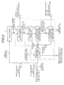
- FIG. 1 is a schematic configuration diagram of an air pollution control system 10A according to a first embodiment.
- the air pollution control system 10A in FIG. 1 removes harmful substances such as nitrogen oxides (NO x ), sulfur oxides (SO x ), and mercury (Hg) from flue gas 25 discharged from a boiler 11 such as a coal combustion boiler that uses coals as a fuel or a heavy-oil combustion boiler that uses heavy oil as a fuel.
- NO x nitrogen oxides
- SO x sulfur oxides
- Hg mercury
- the air pollution control system 10A in FIG. 1 includes NO x removal equipment 12 that removes nitrogen oxides in the flue gas 25 from the boiler 11, an air heater 13 that recovers heat of the flue gas 25 having passed through the NO x removal equipment 12, a precipitator 14 that reduces dust in the flue gas 25 after heat recovery, a desulfurizer 15 that reduces sulfur oxides in the flue gas 25 after dust reduction according to a wet method, a waste-water treatment device 16 that removes harmful substances such as mercury from desulfurized waste water 28 discharged from the desulfurizer 15, and a treated waste-water returning unit 17 (hereinafter, "makeup water line”) that returns at least a part of treated waste water 40 treated by the waste-water treatment device 16 to the desulfurizer 15.
- makeup water line a treated waste-water returning unit 17
- the boiler 11, the NO x removal equipment 12, the air heater 13, the precipitator 14, and the desulfurizer 15 are connected by one flue gas duct D, and the flue gas 25 discharged from the boiler 11 is purified through processes in the respective devices, and then discharged to outside from a stack 27.
- the air pollution control system 10A returns the treated waste water 40 (40A, 40B, and 40C), after harmful substances such as mercury contained in the desulfurized waste water 28 discharged from the desulfurizer 15 are removed, to the desulfurizer 15 so that the treated waste water 40 is circulated between the desulfurizer 15 and the waste water treatment device 16. According to the configuration described above, the mercury concentration in an absorbent to be used in the desulfurizer 15 is decreased.
- the NO x removal equipment 12 removes nitrogen oxides in the flue gas 25 from the boiler 11, and includes an NO x removal catalyst layer (not shown) therein.
- the flue gas 25 introduced into the NO x removal equipment 12 comes in contact with the NO x removal catalyst layer, and nitrogen oxides in the flue gas 25 are decomposed into nitrogen gas (N 2 ) and water (H 2 O) and removed.
- N 2 nitrogen gas
- H 2 O water
- a chlorine (Cl) content in the flue gas 25 increases, the proportion of a bivalent metallic mercury soluble in water increases, and mercury can be easily collected by the desulfurizer 15 described later. Therefore, as shown in FIG.
- an HCl supply system 18 is installed on an upstream side of the NO x removal equipment 12 to supply hydrogen chloride (HCl) 19 into the flue gas 25 in the flue gas duct D from the HCl supply system 18. Accordingly, mercury contained in the flue gas 25 is oxidized (chlorinated) on the NO x removal catalyst, and converted to soluble mercury chloride (HgCl).
- the air heater 13 is a heat exchanger that recovers heat in the flue gas 25 in which nitrogen oxides have been removed by the NO x removal equipment 12. Because the temperature of the flue gas 25 having passed through the NO x removal equipment 12 is as high as about 350°C to 400°C, the air heater 13 performs heat exchange between the high-temperature flue gas 25 and combustion air at a normal temperature. Combustion air, which becomes high temperature by heat exchange, is supplied to the boiler 11. On the other hand, the flue gas 25 having been heat-exchanged with combustion air at a normal temperature is cooled to about 150°C.
- the precipitator 14 reduces dust in the flue gas 25 after heat recovery.
- a centrifugal precipitator, a filtering precipitator, and an electric precipitator can be mentioned; however, it is not particularly limited thereto.
- the desulfurizer 15 reduces sulfur oxides in the flue gas 25 after dust reduction according to a wet method.
- a limestone slurry 20 (a solution in which limestone powder is dissolved in water) is used as an alkaline absorbent, and the temperature inside the desulfurizer is adjusted to about 30°C to 50°C.
- the limestone slurry 20 is supplied from a limestone-slurry supply system 21 to a column bottom part 22 of the desulfurizer 15.
- the limestone slurry 20 supplied to the column bottom part 22 of the desulfurizer 15 is supplied to a or nozzles 23 in the desulfurizer 15 via an absorbent supply line (not shown), and is ejected from the nozzles 23 toward a column top part 24 of the desulfurizer 15. Because the flue gas 25 rising from the column bottom part 22 of the desulfurizer 15 comes in gas-liquid contact with the limestone slurry 20 ejected from the nozzles 23, sulfur oxides and mercury chloride in the flue gas 25 are absorbed by the limestone slurry 20, and separated and removed from the flue gas 25. The flue gas 25 purified by the limestone slurry 20 is discharged from the column top part 24 of the desulfurizer 15 as purged gas 26, and discharged to outside of the system from the stack 27.
- gypsum CaSO 4 ⁇ 2H 2 O is mixed in the limestone slurry 20 to be pumped by an operation of the desulfurizer 15, according to the above reaction expressions (1) and (2).
- the limestone gypsum slurry (a limestone slurry mixed with gypsum) to be pumped is hereinafter referred to as "absorbent".
- the absorbent (the limestone gypsum slurry) used for desulfurizaticn is discharged to outside from the column bottom part 22 of the desulfurizer 15 as the desulfurized waste water 28, and supplied to the waste-water treatment device 16 via a desulfurized waste-water like 29.
- heavy metal such as mercury and halogen ions such as Cl - , Br - , I - , and F - are included in the desulfurized waste water 28.
- mercury Hg is adsorbed by produced gypsum CaSO 4 ⁇ 2H 2 O crystals to reduce mercury.
- a mercury reduction ratio with respect to a gypsum production amount varies according to the property of limestone, the halogen ion concentration, operating conditions of the desulfurizer or the like; however, the ratio is about 2 mg/kg (Hg reduction amount/CaSO 4 ⁇ 2H 2 O production amount).
- mercury may not be adsorbed on gypsum particles.
- the mercury concentration in supernatant liquid of a limestone gypsum slurry increases in the desulfurizer 15, and such a phenomenon occurs that a part of mercury in supernatant liquid scatters from supernatant liquid to a gas phase (flue gas) due to gas-liquid equilibrium. Therefore, the mercury concentration in supernatant liquid needs to be decreased in order to prevent scattering of mercury.
- the treated waste water 40 is returned again to the desulfurizer 15 so that the treated waste water 40 is circulated between the desulfurizer 15 and the waste-water treatment device 16, thereby decreasing the mercury concentration in the absorbent.
- FIG. 2 is a configuration example of the waste-water treatment device 16 shown in FIG. 1 .
- the waste-water treatment device 16 exemplified in FIG. 2 includes a solid-liquid separating unit 31 that separates the desulfurized waste water 28 into a solid fraction including gypsum and a liquid fraction, and a unit 32 that removes substances such as mercury, boron, and selenium remaining in the desulfurized waste water 28 (hereinafter, "mercury removing unit 32").
- the solid-liquid separating unit 31 for example, a belt filter, a centrifugal separator, or a decanter type centrifugal settler is used.
- Gypsum 34 in the desulfurized waste water 28 discharged from the desulfurizer 15 is separated by the solid-liquid separating unit 31.
- mercury chloride in the desulfurized waste water 28 is separated from the liquid together with the gypsum 34 in a state of being adsorbed on gypsum.
- the separated gypsum 34 is discharged to outside of the air pollution control system (hereinafter, "outside of the system").
- the mercury removing unit 32 In the mercury removing unit 32, mercury contained in the separate liquid 35 is solidified, and a mercury solid 36 or the like are separated from the separate liquid 35.
- the mercury removing process includes multi-stage procedures.
- the mercury removing unit 32 includes an auxiliary-agent mixing unit 32a, a solid-liquid separating unit (concentrating unit) 32b, a solid liquid separating unit (dehydrating unit) 32c, and a precision treatment unit 32d.
- the auxiliary-agent mixing unit 32a mixes a coagulation aid into the separate liquid 35 to solidify mercury, and then the solid-liquid separating unit (concentrating unit) 32b concentrates the mercury solid 36 and a particulate matter.
- the solid-liquid separating unit (dehydrating unit) 32c dehydrates the concentrated mercury solid 36 and a articulate matter.
- the dehydrating unit centrifugal separation, a belt filter or the like is used.
- the dehydrated mercury solid 36 or the like are discharged to the outside of the system.
- Separate liquid 38 produced by the solid-liquid separating unit (dehydrating unit) 32c is mixed with the separate liquid 37 separated by the solid-liquid separating unit (concentrating unit) 32b and supplied to the precision treatment unit 32d, where a small amount of a mercury solid 39 and a particulate matter remaining in the separate liquid 37 is removed.
- a method using cyclone separation or membrane separation is used as the precision treatment.
- the mercury solid 39 or the like removed by the mercury removing unit 32 is discharged to the outside of the system.
- the treated waste water 40A in which the mercury solids 36 and 39 are removed by the mercury removing unit 32 is returned to the desulfurizer 15 as makeup water for the desulfurizer 15 via the makeup water line 17.
- the treated waste water 40A returned to the desulfurizer 15 is repeatedly used as an absorbent, and subjected to waste water treatment by the waste-water treatment device 16. That is, the treated waste water 40A is circulated between the desulfurizer 15 and the waste-water treatment device 16.
- An amount of the treated waste water 40A circulated via the waste-water treatment device 16 is determined according to a setting level of the mercury concentration and halogen ion concentration in the absorbent in the desulfurizer 15. For example, when the mercury concentration in the absorbent is set low, the amount of the returned treated waste water 40A is increased.
- FIG. 2 a part of the treated waste water 40A treated by the waste-water treatment device 16 is supplied to an atomized water line 44 described later.
- the waste-water treatment device 16 when an amount of the treated waste water 40A treated by the waste-water treatment device 16 is equal to or less than a set value of an amount of makeup water set beforehand, all the treated waste water 40A is returned to the desulfurizer 15 as makeup water. On the other hand, when the amount of the treated waste water 40A is more than the set value of the amount of makeup water set beforehand, an excess amount of the treated waste water 40A is discharged to the outside of the system.
- the air pollution control system 10A includes the waste-water treatment device 16 having the solid-liquid separating unit 31 that separates the desulfurized water 28 discharged from the desulfurizer 15 into a solid fraction and a liquid fraction, and the mercury removing unit 32 that removes mercury in the desulfurized water 28, and the makeup water line 17 for returning at least a part of the treated waste water 40 treated by the waste-water treatment device 16 to the desulfurizer 15.
- the desulfurized water 28 discharged from the desulfurizer 15 is supplied to the waste-water treatment device 16 to remove mercury, and at least a part of the treated waste water 40A after mercury removal is returned to the desulfurizer 15, so that the treated waste water 40A is circulated between the desulfurizer 15 and the waste-water treatment device 16, thereby enabling to decrease the mercury concentration in the absorbent in the desulfurizer 15.
- mercury in the absorbent is changed from a liquid phase to a gas phase in the desulfurizer 15, and mercury scatters in the flue gas 25 can be suppressed.
- FIG. 3 is a configuration example of the waste-water treatment device 16 according to the second embodiment.
- halogen-ion removing unit 50 removes halogen ions such as chlorine ion (Cl - ), bromine ion (Br - ) , iodine ion (I - ), and fluorine ion (F - ) (hereinafter, "halogen-ion removing unit 50") in addition to the configuration of the waste-water treatment device 16 explained in the first embodiment.
- halogen-ion removing unit 50 removes halogen ions such as chlorine ion (Cl - ), bromine ion (Br - ) , iodine ion (I - ), and fluorine ion (F - )
- Halogen ions such as chlorine ion (Cl - ), bromine ion (Br - ), iodine ion (I - ), and fluorine ion (F - ) have such a property that adsorption of mercury by gypsum is suppressed in the desulfurizing process performed by the desulfurizer 15. Therefore, if the halogen ion concentration in treated waste water to be returned to the desulfurizer 15 is high, the mercury concentration in the supernatant liquid of the absorbent increases, and such a phenomenon occurs that a part of mercury in supernatant liquid scatters to the gas phase (flue gas).
- the halogen-ion removing unit 50 removes halogen ions from separate liquid 41 separated by the mercury removing unit 32, to decrease the halogen ion concentration.
- a concentrating unit using a reverse osmosis membrane, a concentrating unit using an ion exchange membrane, a concentrating unit using electrodialysis can be mentioned, as well as a distillation or crystallization technique.
- the treatment by the halogen-ion removing unit 50 can be performed every time when the separate liquid 41 is supplied from the mercury removing unit 32.
- a configuration can be such that the halogen ion concentration in the separate liquid 41 is measured, and the halogen ions are reduced only when the halogen ion concentration exceeds a set value, and when the halogen ion concentration is less than the set value, the treatment by the halogen-ion removing unit 50 can be omitted.
- the treated waste water 40B in which halogen ions are concentrated and reduced by the halogen-ion removing unit 50 is returned to the desulfurizer 15 via the makeup water line 17 as makeup water for the desulfurizer 15.
- the amount of the treated waste water 40B circulated through the waste-water treatment device 16 is determined according to the setting level of the mercury concentration and the halogen ion concentration in the absorbent in the desulfurizer 15.
- FIG. 3 a part of the treated waste water 40B treated by the waste-water treatment device 16 is supplied to the atomized water line 44 described later. This corresponds to the fourth embodiment described later, and in the second embodiment, the treated waste water 40B is not supplied to the atomized water line 44. Further, in FIG. 3 , concentrated liquid 42 produced by the halogen-ion removing unit 50 is mixed in the atomized water line 44. This also corresponds to the fourth embodiment, and in the second embodiment, the concentrated liquid 42 is discharged to the outside of the system.
- an amount of the treated waste water 40B treated by the waste-water treatment device 16 is equal to or less than a set value of an amount of makeup water set beforehand, all the treated waste water 40B is returned to the desulfurizer 15 as makeup water.
- the amount of the treated waste water 40B is more than the set value of the amount of makeup water set beforehand, an excess amount of the treated waste water 40B is discharged to the outside of the system.
- the waste-water treatment device 16 in the air pollution control system 10A according to the second embodiment includes the halogen-ion removing unit 50 that removes halogen ions such as chlorine ion (Cl - ), bromine ion (Br - ), iodine ion (I - ), and fluorine ion (F - ) that suppress adsorption of mercury on gypsum, in addition to the configuration of the waste-water treatment device 16 explained in the first embodiment.
- the halogen ion concentration in the treated waste water 40 can be decreased. Accordingly, migration of mercury to gypsum (solidification) can be promoted, and scattering of mercury into the gas phase can be suppressed.
- FIG. 4 is a configuration example of the waste-water treatment device 16 according to the third embodiment.
- the waste-water treatment device 16 shown in FIG. 4 includes an auxiliary-agent oxidizing unit 53 in addition to the configuration of the waste-water treatment device 16 explained in the second embodiment.
- a coagulation aid contained in the treated waste water 40 may act as a reducing agent to thereby inhibit oxidation, at the time of returning the treated waste water 40 to the desulfurizer 15.
- the auxiliary-agent oxidizing unit 53 subjects the coagulation aid contained in the separate liquid 41 separated by the precision treatment unit 32d to oxidation treatment.
- an oxidizing agent is added to cause sulfide to react with the oxidizing agent.
- the oxidizing agent air, oxygen O 2 , hydrogen peroxide H 2 O 2 , ozone O 3 , chloric acid compounds, manganese compounds, and iron compounds can be mentioned.
- Halogen ions in the separate liquid 41 subjected to the treatment by the auxiliary-agent oxidizing unit 53 are concentrated and removed by the halogen-ion removing unit 50.
- the treated waste water 40C in which halogen ions are removed is returned to the desulfurizer 15 via the makeup water line 17 as makeup water for the desulfurizer 15.
- the amount of the treated waste water 40C circulated through the waste-water treatment device 16 is determined according to the setting level of the mercury concentration and halogen ion concentration in the absorbent in the desulfurizer 15.
- FIG. 4 a part of the treated waste water 40C treated by the waste-water treatment device 16 is supplied to the atomized water line 44 described later. This corresponds to the fourth embodiment described later, and in the third embodiment, the created waste water 40C is not supplied to the atomized water line 44. Further, in FIG. 4 , the concentrated liquid 42 produced by the halogen-ion removing unit 50 is mixed in the atomized water line 44. This also corresponds to the fourth embodiment, and in the third embodiment, the concentrated liquid 42 is discharged to the outside of the system.
- an amount of the treated waste water 40C treated by the waste-water treatment device 16 is equal to or less than a set value of an amount of makeup water set beforehand, all the treated waste water 40C is returned to the desulfurizer 15 as makeup water.
- the amount of the treated waste water 40C is more than the set value of the amount of makeup water set beforehand, an excess amount of the treated waste water 40C is discharged to the outside of the system.
- the waste-water treatment device 16 in the air pollution control system 10A according to the third embodiment includes the auxiliary-agent oxidizing unit 53 that oxidizes the coagulation aid in addition to the configuration of the waste-water treatment device 16 explained in the second embodiment.
- the air pollution control system 10A of the third embodiment constituted as described above, in addition to effects of the first and second embodiments, such a situation can be prevented that the coagulation aid contained in the treated waste water 40 acts as a reducing agent to inhibit oxidation, at the time of returning the treated waste water 40 to the desulfurizer 15.
- the configurations of the waste-water treatment device 16 exemplified in FIGS. 2 to 4 are only examples, and can be appropriately changed according to the property or the like of the desulfurized waste water 28.
- the mercury removing unit 32 is constituted by multiple stages of a concentrating process, a dehydrating process, and a precision treatment process to remove mercury highly accurately.
- the mercury removing unit 32 does not need to have multiple stages, and any one of these processes can be selected and performed.
- the configuration may be such that the mercury concentration in the separate liquid 37 is measured, and when the mercury concentration is less than a threshold, the precision treatment unit 32d can be omitted.
- the order of the treatment by the solid-liquid separating unit 31, the mercury removing unit 32, and the halogen-ion removing unit 50 is not limited to the example shown in FIG. 2 .
- the treatment by the solid-liquid separating unit 31 can be performed after performing the treatment by the mercury removing unit 32, or the treatment by the mercury removing unit 32 can be performed after performing the treatment by the halogen-ion removing unit 50.
- Fourth embodiment (according to the invention only as far as it includes the features of the claims).
- FIG. 5 is a schematic configuration diagram of an air pollution control system 10B according to the fourth embodiment.
- the treated waste water 40 is returned to the desulfurizer 15 as makeup water.
- a part of the treated waste water 40 is atomized to at least one of a path for supplying the fuel F to the boiler 11, the inside of a furnace of the boiler 11, the inside of the flue gas duct D between the boiler 11 and the air heater 13, and the inside of the bypass pipe 46 and a bypass pipe 47.
- the air pollution control system 10B exemplified in FIG. 5 includes the atomized water line 44 and a waste-water atomizing device 45 in addition to the boiler 11, the NO x removal equipment 12, the air heater 13, the precipitator 14, the desulfurizer 15, the waste-water treatment device 16, and the makeup water line 17.
- the bypass pipe 46 for connecting the flue gas duct D on an upstream side and on a downstream side of the NO x removal equipment 12 is provided at a position parallel to the NO x removal equipment 12.
- the bypass pipe 47 for connecting the flue gas duct D on an upstream side and on a downstream side of the air heater 13 is provided at a position parallel to the air heater 13.
- the treated waste water 40 can be atomized also into the flue gas 25 circulating in the respective bypass pipes 46 and 47.
- the respective bypass pipes 46 and 47 are configured such that an amount of flue gas circulating therein becomes about several percents of the amount of flue gas circulating in the flue gas duct D.
- Predetermined amount of the treated waste water 40 treated by the waste-water treatment device 16 is returned to the desulfurizer 15 via the makeup water line 17.
- the remaining treated waste water 40 is supplied to the atomized water line 44, so that the treated waste water 40 is supplied to the path for supplying the fuel F to the boiler 11, the inside of a furnace of the boiler 11, the inside of the flue gas duct D, and the inside of the bypass pipes 46 and 47 by the waste-water atomizing device 45.
- the amount of treated waste water 40 treated by the waste-water treatment device 16 is equal to or less than the set value of the amount of makeup water set beforehand, all the treated waste water 40 is returned to the desulfurizer 15 as makeup water.
- the amount of the treated waste water 40 is more than the set value of the amount of makeup water set beforehand, an excess amount of the treated waste water 40 is supplied to the atomized water line 44, so that the waste-water atomizing device 45 supplies the treated waste water 40 to the path for supplying the fuel F to the boiler 11, and to the inside of the boiler 11, the flue gas duct D, and the bypass pipes 46 and 47.
- the excess amount of the treated waste water 40 is discharged to the outside of the system.
- the amount of the treated waste water 40 (makeup water) to be returned to the desulfurizer 15 is determined according to a setting level of the mercury concentration and halogen ion concentration in the absorbent in the desulfurizer 15.
- the amount of the treated waste water 40 (makeup water) to be atomized to the inside of a furnace of the boiler 11, the inside of the flue gas duct D, and the inside of the bypass pipes 46 and 47 is determined according to the amount of the treated waste water 40 produced in proportion to the treated amount of the flue gas 25 and an amount limit of the treated waste water 40 that can be discharged to the outside of the system.
- any one of the configurations explained in the first embodiment ( FIG. 2 ) to the third embodiment ( FIG. 4 ) is applied to the waste-water treatment device 16.
- the waste-water treatment device 16 includes the solid-liquid separating unit 31 and the mercury removing unit 32 as shown in FIG. 2
- a part of the treated waste water 40A treated in the mercury removing unit 32 is supplied to the atomized water line 44.
- the waste-water treatment device 16 includes the mercury removing unit 32 and the halogen-ion removing unit 50 as shown in FIG. 3
- the separate liquid 41 treated in the mercury removing unit 32, or liquid in which the concentrated liquid 42 of halogen ions is mixed with the separate liquid 41 is supplied to the atomized water line 44 as the treated waste water 40B.
- the treated waste water 40 is to be atomized into the flue gas duct D on an upstream side of the NO x removal equipment 12
- mixed liquid of the concentrated liquid 42 of halogen ions and the separate liquid 41 is supplied to the atomized water line 44 as the treated waste water 40B, and atomized into the flue gas duct D.
- the concentration of chlorine ions in the flue gas 25 can be increased, thereby enabling to increase conversion efficiency of mercury chloride in the NO x removal equipment 12.
- the concentrated liquid 42 of halogen ions is not mixed, and only the separate liquid 41 is supplied to the atomized water line 44 as the treated waste water 40B, and atomized into the flue gas duct D and the bypass pipes 46 and 47.
- the waste-water treatment device 16 includes the solid-liquid separating unit 31, the mercury removing unit 32, the auxiliary-agent oxidizing unit 53, and the halogen-ion removing unit 50 as shown in FIG. 4 .
- the waste-water atomizing device 45 includes a waste water tank 48 connected to the waste-water treatment device 16 via the atomized water line 44 to accumulate the treated waste water (atomized water) 40, and a plurality of waste-water supply pipes (waste-water supplying units) P0 to P5 respectively connected to the waste water tank 48 to supply the treated waste water 40 accumulated in the waste water tank 48 into the path for supplying the fuel F to the boiler 11, the inside of a furnace of the boiler 11, the inside of the flue gas duct D, and the inside of the bypass pipes 46 and 47.
- Nozzles N1 to N5 for atomizing the treated waste water 40 are provided at the ends of the waste-water supplying pipes P1 to P5.
- the waste-water supplying pipes P0 to P5 are installed at positions where the high-temperature flue gas 25 before heat recovery by the air heater 13 is circulated, that is, on the upstream side of the air heater 13.
- the waste-water supplying pipe P1 is connected to the boiler 11, and the nozzle N1 is installed at the inside of a furnace of the boiler 11.
- the nozzle N1 is installed on the side of a furnace or on a furnace wall in an upper part of the furnace, so that the desulfurized waste water 28 is atomized from the nozzle N1 toward a flame portion at the center of the furnace or above the flame.
- the waste-water supplying pipe P2 is connected to the flue gas duct D between the boiler 11 and the NO x removal equipment 12, and the nozzle N2 is installed at the inside of the flue gas duct D.
- the waste-water supplying pipe P3 is connected to the bypass pipe 46 for connecting the flue gas ducts D on the upstream side and on the downstream side of the NO x removal equipment 12, and the nozzle N3 is installed at the inside of the bypass pipe 46.
- the waste-water supplying pipe P4 is connected to the flue gas duct D between the NO x removal equipment 12 and the air heater 13, and the nozzle N4 is installed at the inside of the flue gas duct D.
- the waste-water supplying pipe P5 is connected to the bypass pipe 47 for connecting the flue gas ducts D on the upstream side and on the downstream side of the air heater 13, and the nozzle N5 is installed at the inside of the bypass pipe 47.
- nozzles N1 to N5 for example, a two-fluid nozzle or a rotary atomizer is used. It is desired that a mist diameter of the nozzles N1 to N5 is such that a maximum particle diameter is equal to or less than 200 micrometers and an average particle diameter is from 30 to 70 micrometers. Accordingly, contact efficiency with the flue gas 25 is improved, thereby enabling to improve evaporation efficiency.
- the flue gas temperature in a furnace of the boiler 11 where the nozzle N1 is installed is as high as 800°C to 1200°C, which is the highest temperature in the system, and thus a largest amount of the treated waste water 40 can be evaporated.
- the flue gas temperature inside the flue gas duct D where the nozzle N2 is installed is about 500°C
- the flue gas temperature inside the flue gas duct D where the nozzle N4 is installed and in the bypass pipes 46 and 47 where the nozzles N3 and N5 are installed is respectively about 350°C to 400°C, and although the temperature is lower than that in the furnace of the boiler 11, the treated waste water 40 can be reliably evaporated.
- the temperature of the flue gas 25 having passed through the air heater 13 decreases to about 150°C, and thus the treated waste water 40 cannot be evaporated sufficiently.
- the waste-water supplying pipe P0 is installed in the path for supplying the fuel F to the boiler 11.
- the path for supplying the fuel F to the boiler 11 is, specifically, inside of a fuel supply system (not shown) or a pipe for connecting the fuel supply system and the boiler 11.
- the treated waste water 40 supplied from the waste-water supplying pipe P0 into the fuel F is mixed with the fuel F, input to the boiler 11 together with the fuel F, and evaporated in the boiler.
- Opening/closing valves V0 to V5 are respectively installed in the waste-water supplying pipes P0 to P5, and by controlling an opening/closing degree of the opening/closing valves V0 to V5, a flow rate of the treated waste water 40 to be supplied to the waste-water supplying pipes P0 to P5 is adjusted.
- the treated waste water 40 accumulated in the waste water tank 48 is atomized respectively into the path for supplying the fuel F to the boiler 11, the inside of a furnace of the boiler 11, the inside of the flue gas duct D, and the inside of the bypass pipes 46 and 47, through the waste-water supplying pipes P1 to P5.
- the treated waste water 40 atomized from the nozzles N1 to N5 into the high-temperature flue gas 25 is evaporated to become water vapor, and thereafter, supplied into the desulfurizer 15 together with the flue gas 25. Because the temperature in the desulfurizer 15 is as high as 30°C to 50°C, most of the water vapor introduced into the desulfurizer 15 is devolatilized, and mixed with the limestone slurry 20 in the column bottom part 22. Meanwhile, the water vapor, which is not devolatilized, is discharged from the stack 27 together with the purged gas 26.
- the temperature of the flue gas 25 is different according to positions in the flue gas duct D, and evaporation efficiency of the desulfurized waste water 28 is also different. Therefore, the opening/closing degree of the valves V0 to V5 is optimized, taking into consideration delivery efficiency of dry particles and evaporation efficiency of the flue gas 25.
- the waste-water supplying pipes P0 to P5 that supply the treated waste water 40 to at least one of the path for supplying the fuel F to the boiler 11, the inside of a furnace of the boiler 11, the inside of the flue gas duct D, and the inside of the bypass pipes 46 and 47 are installed, in addition to the configuration of the first to third embodiments. At least a part of the treated waste water 40 treated by the waste-water treatment device 16 is returned to the desulfurizer 15 as makeup water, whereas a part of the treated waste water 40 is supplied to the path for supplying the fuel F to the boiler 11, the inside of a furnace of the boiler 11, the inside of the flue gas duct D or the like.
- the treated waste water 40 treated by the waste-water treatment device 16 can be reused to a maximum extent, in addition to effects in the first to third embodiments, and all the treated waste water 40 can be reused in the air pollution control system 10B. As a result, discharge of waste water to the outside of the system can be considerably decreased, or can be eliminated completely.
- the treated waste water 40 is directly atomized into the high-temperature flue gas 25 before heat recovery by the air heater 13, even if the amount of the treated waste water 40 to be atomized from the nozzles N1 to N5 is large, the treated waste water 40 can be evaporated reliably, and an amount of the treated waste water 40 to be returned to the flue gas duct D per unit time can be increased. As a result, the amount of the desulfurized waste water 28 per time unit can be increased, thereby enabling to increase throughput of flue gas per time unit as compared to conventional methods.
- bypass pipes 46 and 47 are provided respectively at positions parallel to the NO x removal equipment 12 and the air heater 13, and the treated waste water 40 is atomized into the flue gas 25 inside the bypass pipes 46 and 47 and evaporated. Therefore, when there is a possibility that dry particles such as ash generated due to evaporation of the treated waste water 40 pass through the NO x removal equipment 12 and the air heater 13 to decrease effects of these devices, dry particles can be efficiently delivered to the downstream side of the No x removal equipment 12 and the air heater 13 via the respective bypass pipes 46 and 47.
- the configuration of the waste-water atomizing device 45 shown in FIG. 5 is only an example, and the number of installation and installation positions of the waste-water supplying pipes P0 to P5 are not limited thereto, and can be appropriately changed according to the amount of the treated waste water 40 and the kind of the flue gas 25. That is, the waste-water supplying pipes P0 to P5 only need to be installed at least at one position of the path for supplying the fuel F to the boiler 11, the inside of a furnace of the boiler 11, the flue gas duct D from an outlet of the boiler 11 to an inlet of the air heater, and the bypass pipes 46 and 47.
- the bypass pipes 46 and 47 do not need to be provided.
- the treated waste water 40 from the waste-water treatment device 16 is temporarily accumulated in the waste water tank 48, and the treated waste water 40 is supplied from the waste water tank 48 to the waste-water supplying pipes P0 to P5.
- the treated waste water 40 supplied from the waste-water treatment device 16 via the atomized water line 44 can be directly supplied to the waste-water supplying pipes P0 to P5.
- the air pollution control system and the air pollution control method of the present invention because it is possible to decrease the mercury concentration in an absorbent in a desulfurizer, scattering of mercury in flue gas in the desulfurizer can be suppressed.
Description
- The present invention reflates to an air pollution control system and an air pollution control method for purifying flue gas discharged from a boiler.
- Conventionally, there has been known an air pollution control system for treating flue gas discharged from a boiler installed in a thermal power generation plant or the like. The air pollution control system includes NOx removal equipment that removes nitrogen oxides from flue gas discharged from a boiler, an air heater that recovers heat of flue gas having passed through the NOx removal equipment, a precipitator that reduces dust in the flue gas after heat recovery, and a desulfurizer that reduces sulfur oxides in the flue gas after dust reduction. As the desulfurizer, a wet desulfurizer that reduces sulfur oxides in flue gas by bringing an absorbent such as a limestone slurry into gas-liquid contact with flue gas has been generally used.
- In flue gas discharged from the boiler, harmful substances such gas mercury may be contained in a small amount other than nitrogen oxides and sulfur oxides. In the air pollution, control system described above, therefore, as a method of removing mercury in flue gas, such a method has been used that a chlorinating agent is gas-atomized on an upstream or high-temperature NOx removal equipment in a flue gas duct, mercury is oxidized (chlorinated) on an NOx removal catalyst to prepare soluble mercury chloride, and mercury chloride is dissolved in an absorbent by a downstream wet desulfurizer (see, for example, Patent Literature 1).
-
Patent Literature 2 discloses an air pollution control system as per the preamble of claim 1. - Patent Literature 3 discloses the use of a sulphide coagulant to precipitate the mercury in waste water resulting from a wet scrubber.
-
- Patent Literature 1: Japanese Patent Application Laid-open No.
2009-262081 - Patent Literature 2: International Patent Application
WO 2009/093576 - Patent Literature 3: European Patent Application
EP 1837075 Summary - In the mercury removal method described above, if mercury chloride in flue gas is dissolved in an absorbent, the mercury concentration in the absorbent increases and the phase of mercury is changed from liquid phase to gas phase due to gas-liquid equilibrium, thereby causing a problem that mercury scatters in flue gas in the desulfurizer.
- Therefore, it has been desired to suppress scattering of mercury in flue gas in the desulfurizer.
- The present invention has been achieved to solve the above problem, and an object of the present invention is to provide an air pollution control system and an air pollution control method capable of suppressing scattering of mercury in flue gas in a desulfurizer.
- According to an aspect of the present invention, an air pollution control system includes: a boiler that burns fuel; a NOx removal equipment that decomposes nitrogen oxides in flue gas discharged from the boiler; and a desulfurizer that causes sulfur oxides in flue gas having passed through the NOx removal equipment to be absorbed by an absorbent, thereby reducing the sulfur oxides in the flue gas; a waste-water treatment device including a solid-liquid separating unit that separates waste water discharged from the desulfurizer into a solid fraction and a liquid fraction, and a mercury removing unit that removes mercury in the waste water; and a treated waste-water returning unit that returns at least a part of treated waste water treated by the waste-water treatment device to the desulfurizer wherein
the mercury removing unit includes a separating unit that separates mercury solids from the waste water by adding a coagulation aid into the waste water to solidify the mercury
the coagulation aid is sulfide, and
the waste-water treatment device includes an auxiliary-agent oxidizing unit that oxidizes the coagulation aid contained in separate liquid in which the mercury solids have been separated. - Advantageously, in the air pollution control system, the waste-water treatment device includes a halogen-ion removing unit that removes halogen ions in the waste water.
- Advantageously, the air pollution control system further includes: an air heater provided between the NOx removal equipment and the desulfurizer to recover heat of the flue gas; and a waste-water supplying unit installed at least at one position of a path for supplying fuel to the boiler, inside of the boiler, and inside of a flue gas duct between the boiler and the air heater, to supply a part of treated waste water treated by the waste-water treatment device.
- Advantageously, in the air pollution control system, a bypass pipe is provided at least in one position parallel to the NOx removal equipment or parallel to the air heater, and the waste-water supplying unit is provided in the bypass pipe.
- According to another aspect of the present invention, an air pollution control method includes: a NOx removing step of decomposing nitrogen oxides in flue gas discharged from a boiler that burns fuel by NOx removal equipment; a desulfurizing step of causing sulfur oxides in flue gas having passed through the NOx removal equipment to be absorbed by an absorbent in a desulfurizer, thereby reducing the sulfur oxides in the flue gas; a waste-water treating step including a solid-liquid separating step of separating waste water discharged from the desulfurizer into a solid fraction and a liquid fraction, and a mercury removing step of removing mercury in the waste water; and a treated waste-water returning step of returning at least a part of treated waste water treated at the waste-water treating step to the desulfurizer wherein
the mercury removing step in the waste-water treating step is a step of separating mercury solids from the waste water (28) by adding a coagulation aid into the waste water (28) to solidify the mercury,
the coagulation aid is sulfide, and
the waste-water treating step includes an oxidizing step of oxidizing the coagulation aid contained in separate liquid in which the mercury solids have been separated. - Advantageously, in the air pollution control method, the waste-water treating step includes a halogen-ion removing step of removing halogen ions in the waste water.
- Advantageously, in the air pollution control method, an air heater that recovers heat of the flue gas is provided between the NOx removal equipment and the desulfurizer; and the air pollution control method further comprises a waste-water supplying step of supplying a part of treated waste water treated at the waste-water treating step to at least one of a path for supplying fuel to the boiler, inside of the boiler, and inside of a flue gas duct between the boiler and the air heater.
- Advantageously, in the air pollution control method, a bypass pipe is provided at least in one position parallel to the NOx removal equipment or parallel to the air heater, and the treated waste water is supplied to inside of the bypass pipe.
- According to the air pollution control system and the air pollution control method of the present invention, treated waste water after mercury in desulfurized waste water discharged from a desulfurizer is removed is returned to the desulfurizer, thereby enabling to decrease the mercury concentration in an absorbent in the desulfurizer. As a result, scattering of mercury in flue gas in the desulfurizer can be suppressed.
-
-
FIG. 1 is a schematic configuration diagram of an air pollution control system according to a first embodiment (not according to the invention). -
FIG. 2 is a configuration example of a waste-water treatment device according to the first embodiment (not according to the invention). -
FIG. 3 is a configuration example of a waste-water treatment device according to a second embodiment (not according to the invention). -
FIG. 4 is a configuration example of a waste-water treatment device according to a third embodiment. -
FIG. 5 is a schematic configuration diagram of an air pollution control system according to a fourth embodiment (according to the invention only as far as it contains the features of the third embodiment). - Exemplary embodiments of the present invention will be explained below in detail with reference to the accompanying drawings. The present invention is not limited to the embodiments. In addition, constituent elements in the following embodiments include those that can be easily assumed by persons skilled in the art or that are substantially equivalent.
- First embodiment (not according to the invention).
-
FIG. 1 is a schematic configuration diagram of an airpollution control system 10A according to a first embodiment. The airpollution control system 10A inFIG. 1 removes harmful substances such as nitrogen oxides (NOx), sulfur oxides (SOx), and mercury (Hg) fromflue gas 25 discharged from aboiler 11 such as a coal combustion boiler that uses coals as a fuel or a heavy-oil combustion boiler that uses heavy oil as a fuel. - The air
pollution control system 10A inFIG. 1 includes NOx removal equipment 12 that removes nitrogen oxides in theflue gas 25 from theboiler 11, anair heater 13 that recovers heat of theflue gas 25 having passed through the NOx removal equipment 12, aprecipitator 14 that reduces dust in theflue gas 25 after heat recovery, adesulfurizer 15 that reduces sulfur oxides in theflue gas 25 after dust reduction according to a wet method, a waste-water treatment device 16 that removes harmful substances such as mercury fromdesulfurized waste water 28 discharged from thedesulfurizer 15, and a treated waste-water returning unit 17 (hereinafter, "makeup water line") that returns at least a part of treatedwaste water 40 treated by the waste-water treatment device 16 to thedesulfurizer 15. Theboiler 11, the NOx removal equipment 12, theair heater 13, theprecipitator 14, and thedesulfurizer 15 are connected by one flue gas duct D, and theflue gas 25 discharged from theboiler 11 is purified through processes in the respective devices, and then discharged to outside from astack 27. The airpollution control system 10A returns the treated waste water 40 (40A, 40B, and 40C), after harmful substances such as mercury contained in thedesulfurized waste water 28 discharged from thedesulfurizer 15 are removed, to thedesulfurizer 15 so that the treatedwaste water 40 is circulated between thedesulfurizer 15 and the wastewater treatment device 16. According to the configuration described above, the mercury concentration in an absorbent to be used in thedesulfurizer 15 is decreased. - The NOx removal equipment 12 removes nitrogen oxides in the
flue gas 25 from theboiler 11, and includes an NOx removal catalyst layer (not shown) therein. In a NOx removing process, theflue gas 25 introduced into the NOx removal equipment 12 comes in contact with the NOx removal catalyst layer, and nitrogen oxides in theflue gas 25 are decomposed into nitrogen gas (N2) and water (H2O) and removed. When a chlorine (Cl) content in theflue gas 25 increases, the proportion of a bivalent metallic mercury soluble in water increases, and mercury can be easily collected by thedesulfurizer 15 described later. Therefore, as shown inFIG. 1 , anHCl supply system 18 is installed on an upstream side of the NOx removal equipment 12 to supply hydrogen chloride (HCl) 19 into theflue gas 25 in the flue gas duct D from theHCl supply system 18. Accordingly, mercury contained in theflue gas 25 is oxidized (chlorinated) on the NOx removal catalyst, and converted to soluble mercury chloride (HgCl). - The
air heater 13 is a heat exchanger that recovers heat in theflue gas 25 in which nitrogen oxides have been removed by the NOx removal equipment 12. Because the temperature of theflue gas 25 having passed through the NOx removal equipment 12 is as high as about 350°C to 400°C, theair heater 13 performs heat exchange between the high-temperature flue gas 25 and combustion air at a normal temperature. Combustion air, which becomes high temperature by heat exchange, is supplied to theboiler 11. On the other hand, theflue gas 25 having been heat-exchanged with combustion air at a normal temperature is cooled to about 150°C. - The
precipitator 14 reduces dust in theflue gas 25 after heat recovery. As theprecipitator 14, a centrifugal precipitator, a filtering precipitator, and an electric precipitator can be mentioned; however, it is not particularly limited thereto. - The
desulfurizer 15 reduces sulfur oxides in theflue gas 25 after dust reduction according to a wet method. In thedesulfurizer 15, a limestone slurry 20 (a solution in which limestone powder is dissolved in water) is used as an alkaline absorbent, and the temperature inside the desulfurizer is adjusted to about 30°C to 50°C. In a desulfurizing process, thelimestone slurry 20 is supplied from a limestone-slurry supply system 21 to a columnbottom part 22 of thedesulfurizer 15. Thelimestone slurry 20 supplied to the columnbottom part 22 of thedesulfurizer 15 is supplied to a ornozzles 23 in thedesulfurizer 15 via an absorbent supply line (not shown), and is ejected from thenozzles 23 toward a columntop part 24 of thedesulfurizer 15. Because theflue gas 25 rising from the columnbottom part 22 of thedesulfurizer 15 comes in gas-liquid contact with thelimestone slurry 20 ejected from thenozzles 23, sulfur oxides and mercury chloride in theflue gas 25 are absorbed by thelimestone slurry 20, and separated and removed from theflue gas 25. Theflue gas 25 purified by thelimestone slurry 20 is discharged from the columntop part 24 of thedesulfurizer 15 as purgedgas 26, and discharged to outside of the system from thestack 27. - At the inside of the
desulfurizer 15, sulfur oxides SOx in theflue gas 25 causes a reaction with thelimestone slurry 20 represented by the following expression (1).
CaCO3+SO2+0.5H2O → CaSO3·0.5H2O+CO2 ... (1)
- The
limestone slurry 20 that has absorbed SOx in theflue gas 25 is then oxidized by air (not shown) supplied to the columnbottom part 22 of thedesulfurizer 15, to cause a reaction with air represented by the following expression (2).
CaSO3·0.5H2O+0.5O2+1.5H2O → CaSO4·2H2O ... (2)
- In this manner, SOx in the
flue gas 25 is captured in a state of gypsum CaSO4·2H2O in thedesulfurizer 15. - As described above, while a solution accumulated in the column
bottom part 22 of thedesulfurizer 15 of a wet type and pumped is used as thelimestone slurry 20, gypsum CaSO4·2H2O is mixed in thelimestone slurry 20 to be pumped by an operation of thedesulfurizer 15, according to the above reaction expressions (1) and (2). The limestone gypsum slurry (a limestone slurry mixed with gypsum) to be pumped is hereinafter referred to as "absorbent". - The absorbent (the limestone gypsum slurry) used for desulfurizaticn is discharged to outside from the column
bottom part 22 of thedesulfurizer 15 as the desulfurizedwaste water 28, and supplied to the waste-water treatment device 16 via a desulfurized waste-water like 29. As well as gypsum, heavy metal such as mercury and halogen ions such as Cl-, Br-, I-, and F- are included in the desulfurizedwaste water 28. - In the
desulfurizer 15, mercury Hg is adsorbed by produced gypsum CaSO4·2H2O crystals to reduce mercury. A mercury reduction ratio with respect to a gypsum production amount varies according to the property of limestone, the halogen ion concentration, operating conditions of the desulfurizer or the like; however, the ratio is about 2 mg/kg (Hg reduction amount/CaSO4·2H2O production amount). In coal having a high mercury content ratio (or low sulfur content ratio) with a ratio by weight being equal to or higher than 2 mg/kg, mercury may not be adsorbed on gypsum particles. In this case, the mercury concentration in supernatant liquid of a limestone gypsum slurry increases in thedesulfurizer 15, and such a phenomenon occurs that a part of mercury in supernatant liquid scatters from supernatant liquid to a gas phase (flue gas) due to gas-liquid equilibrium. Therefore, the mercury concentration in supernatant liquid needs to be decreased in order to prevent scattering of mercury. As explained below, therefore, after the desulfurizedwaste water 28 is supplied to the waste-water treatment device 16 and a waste-water treating process including a solid-liquid separating process and a mercury removing process is performed, the treatedwaste water 40 is returned again to thedesulfurizer 15 so that the treatedwaste water 40 is circulated between the desulfurizer 15 and the waste-water treatment device 16, thereby decreasing the mercury concentration in the absorbent. -
FIG. 2 is a configuration example of the waste-water treatment device 16 shown inFIG. 1 . The waste-water treatment device 16 exemplified inFIG. 2 includes a solid-liquid separating unit 31 that separates the desulfurizedwaste water 28 into a solid fraction including gypsum and a liquid fraction, and aunit 32 that removes substances such as mercury, boron, and selenium remaining in the desulfurized waste water 28 (hereinafter, "mercury removing unit 32"). - As the solid-
liquid separating unit 31, for example, a belt filter, a centrifugal separator, or a decanter type centrifugal settler is used.Gypsum 34 in the desulfurizedwaste water 28 discharged from thedesulfurizer 15 is separated by the solid-liquid separating unit 31. At this time, mercury chloride in the desulfurizedwaste water 28 is separated from the liquid together with thegypsum 34 in a state of being adsorbed on gypsum. The separatedgypsum 34 is discharged to outside of the air pollution control system (hereinafter, "outside of the system"). On the other hand, a small amount of substances such as mercury, boron, and selenium (mercury is specifically explained below as the substance) that cannot be adsorbed on thegypsum 34 is contained inseparate liquid 35. These substances are removed by themercury removing unit 32 described below. - In the
mercury removing unit 32, mercury contained in theseparate liquid 35 is solidified, and a mercury solid 36 or the like are separated from theseparate liquid 35. In an example shown inFIG. 2 , to perform highly accurate mercury removal, the mercury removing process includes multi-stage procedures. Themercury removing unit 32 includes an auxiliary-agent mixing unit 32a, a solid-liquid separating unit (concentrating unit) 32b, a solid liquid separating unit (dehydrating unit) 32c, and aprecision treatment unit 32d. The auxiliary-agent mixing unit 32a mixes a coagulation aid into theseparate liquid 35 to solidify mercury, and then the solid-liquid separating unit (concentrating unit) 32b concentrates the mercury solid 36 and a particulate matter. As the concentrating unit, gravitational settling, sand filtration or the like is used. The solid-liquid separating unit (dehydrating unit) 32c dehydrates the concentrated mercury solid 36 and a articulate matter. As the dehydrating unit, centrifugal separation, a belt filter or the like is used. The dehydrated mercury solid 36 or the like are discharged to the outside of the system. Separate liquid 38 produced by the solid-liquid separating unit (dehydrating unit) 32c is mixed with theseparate liquid 37 separated by the solid-liquid separating unit (concentrating unit) 32b and supplied to theprecision treatment unit 32d, where a small amount of a mercury solid 39 and a particulate matter remaining in theseparate liquid 37 is removed. As the precision treatment, a method using cyclone separation or membrane separation is used. The mercury solid 39 or the like removed by themercury removing unit 32 is discharged to the outside of the system. - The treated
waste water 40A in which themercury solids mercury removing unit 32 is returned to thedesulfurizer 15 as makeup water for thedesulfurizer 15 via themakeup water line 17. The treatedwaste water 40A returned to thedesulfurizer 15 is repeatedly used as an absorbent, and subjected to waste water treatment by the waste-water treatment device 16. That is, the treatedwaste water 40A is circulated between the desulfurizer 15 and the waste-water treatment device 16. An amount of the treatedwaste water 40A circulated via the waste-water treatment device 16 (an amount of the returned treatedwaste water 40A) is determined according to a setting level of the mercury concentration and halogen ion concentration in the absorbent in thedesulfurizer 15. For example, when the mercury concentration in the absorbent is set low, the amount of the returned treatedwaste water 40A is increased. - In
FIG. 2 , a part of the treatedwaste water 40A treated by the waste-water treatment device 16 is supplied to an atomizedwater line 44 described later. This corresponds to a fourth embodiment described later, and in the first embodiment, the treatedwaste water 40A is not supplied to the atomized water like 44. - That is, in the first embodiment, when an amount of the treated
waste water 40A treated by the waste-water treatment device 16 is equal to or less than a set value of an amount of makeup water set beforehand, all the treatedwaste water 40A is returned to thedesulfurizer 15 as makeup water. On the other hand, when the amount of the treatedwaste water 40A is more than the set value of the amount of makeup water set beforehand, an excess amount of the treatedwaste water 40A is discharged to the outside of the system. - As described above, the air
pollution control system 10A according to the first embodiment includes the waste-water treatment device 16 having the solid-liquid separating unit 31 that separates the desulfurizedwater 28 discharged from thedesulfurizer 15 into a solid fraction and a liquid fraction, and themercury removing unit 32 that removes mercury in the desulfurizedwater 28, and themakeup water line 17 for returning at least a part of the treatedwaste water 40 treated by the waste-water treatment device 16 to thedesulfurizer 15. The desulfurizedwater 28 discharged from thedesulfurizer 15 is supplied to the waste-water treatment device 16 to remove mercury, and at least a part of the treatedwaste water 40A after mercury removal is returned to thedesulfurizer 15, so that the treatedwaste water 40A is circulated between the desulfurizer 15 and the waste-water treatment device 16, thereby enabling to decrease the mercury concentration in the absorbent in thedesulfurizer 15. As a result, such a situation that mercury in the absorbent is changed from a liquid phase to a gas phase in thedesulfurizer 15, and mercury scatters in theflue gas 25 can be suppressed. - An air pollution control system according to a second embodiment (not according to the invention) is explained next. Because constituent elements of the air pollution control system according to the second embodiment are identical to those of the air
pollution control system 10A shown inFIG. 1, FIG. 1 is also used for explanations thereof.FIG. 3 is a configuration example of the waste-water treatment device 16 according to the second embodiment. The waste-water treatment device 16 shown inFIG. 3 includes aunit 50 that removes halogen ions such as chlorine ion (Cl-), bromine ion (Br-) , iodine ion (I-), and fluorine ion (F-) (hereinafter, "halogen-ion removing unit 50") in addition to the configuration of the waste-water treatment device 16 explained in the first embodiment. - Halogen ions such as chlorine ion (Cl-), bromine ion (Br-), iodine ion (I-), and fluorine ion (F-) have such a property that adsorption of mercury by gypsum is suppressed in the desulfurizing process performed by the
desulfurizer 15. Therefore, if the halogen ion concentration in treated waste water to be returned to thedesulfurizer 15 is high, the mercury concentration in the supernatant liquid of the absorbent increases, and such a phenomenon occurs that a part of mercury in supernatant liquid scatters to the gas phase (flue gas). Therefore, it is desired that the halogen-ion removing unit 50 removes halogen ions from separate liquid 41 separated by themercury removing unit 32, to decrease the halogen ion concentration. As the halogen-ion removing unit 50, a concentrating unit using a reverse osmosis membrane, a concentrating unit using an ion exchange membrane, a concentrating unit using electrodialysis can be mentioned, as well as a distillation or crystallization technique. - The treatment by the halogen-
ion removing unit 50 can be performed every time when theseparate liquid 41 is supplied from themercury removing unit 32. However, a configuration can be such that the halogen ion concentration in theseparate liquid 41 is measured, and the halogen ions are reduced only when the halogen ion concentration exceeds a set value, and when the halogen ion concentration is less than the set value, the treatment by the halogen-ion removing unit 50 can be omitted. - The treated
waste water 40B in which halogen ions are concentrated and reduced by the halogen-ion removing unit 50 is returned to thedesulfurizer 15 via themakeup water line 17 as makeup water for thedesulfurizer 15. Similarly to the first embodiment, the amount of the treatedwaste water 40B circulated through the waste-water treatment device 16 is determined according to the setting level of the mercury concentration and the halogen ion concentration in the absorbent in thedesulfurizer 15. - In
FIG. 3 , a part of the treatedwaste water 40B treated by the waste-water treatment device 16 is supplied to the atomizedwater line 44 described later. This corresponds to the fourth embodiment described later, and in the second embodiment, the treatedwaste water 40B is not supplied to the atomizedwater line 44. Further, inFIG. 3 ,concentrated liquid 42 produced by the halogen-ion removing unit 50 is mixed in the atomizedwater line 44. This also corresponds to the fourth embodiment, and in the second embodiment, theconcentrated liquid 42 is discharged to the outside of the system. - Similarly to the first embodiment, when an amount of the treated
waste water 40B treated by the waste-water treatment device 16 is equal to or less than a set value of an amount of makeup water set beforehand, all the treatedwaste water 40B is returned to thedesulfurizer 15 as makeup water. On the other hand, when the amount of the treatedwaste water 40B is more than the set value of the amount of makeup water set beforehand, an excess amount of the treatedwaste water 40B is discharged to the outside of the system. - As explained above, the waste-
water treatment device 16 in the airpollution control system 10A according to the second embodiment includes the halogen-ion removing unit 50 that removes halogen ions such as chlorine ion (Cl-), bromine ion (Br-), iodine ion (I-), and fluorine ion (F-) that suppress adsorption of mercury on gypsum, in addition to the configuration of the waste-water treatment device 16 explained in the first embodiment. According to the airpollution control system 10A of the second embodiment constituted as described above, in addition to effects of the first embodiment, the halogen ion concentration in the treatedwaste water 40 can be decreased. Accordingly, migration of mercury to gypsum (solidification) can be promoted, and scattering of mercury into the gas phase can be suppressed. - An air pollution control system according to a third embodiment is explained next. Because constituent elements of the air pollution control system according to the third embodiment are identical to those of the air
pollution control system 10A shown inFIG. 1, FIG. 1 is also used for explanations thereof.FIG. 4 is a configuration example of the waste-water treatment device 16 according to the third embodiment. The waste-water treatment device 16 shown inFIG. 4 includes an auxiliary-agent oxidizing unit 53 in addition to the configuration of the waste-water treatment device 16 explained in the second embodiment. In an auxiliary-agent mixing process performed by themercury removing unit 32, when sulfide such as hydrogen sulfide H2S, sodium sulfide Na2S, sodium hydrogen sulfide NaHS, or metal sulfide MxSy (M is a metal element such as Mn or Fe, and x and y are numbers) is used, a coagulation aid contained in the treatedwaste water 40 may act as a reducing agent to thereby inhibit oxidation, at the time of returning the treatedwaste water 40 to thedesulfurizer 15. Therefore, since sulfide is used as the coagulation aid, it is desired that the auxiliary-agent oxidizing unit 53 subjects the coagulation aid contained in theseparate liquid 41 separated by theprecision treatment unit 32d to oxidation treatment. As the oxidation treatment, specifically, an oxidizing agent is added to cause sulfide to react with the oxidizing agent. As the oxidizing agent, air, oxygen O2, hydrogen peroxide H2O2, ozone O3, chloric acid compounds, manganese compounds, and iron compounds can be mentioned. - Halogen ions in the
separate liquid 41 subjected to the treatment by the auxiliary-agent oxidizing unit 53 are concentrated and removed by the halogen-ion removing unit 50. The treatedwaste water 40C in which halogen ions are removed is returned to thedesulfurizer 15 via themakeup water line 17 as makeup water for thedesulfurizer 15. Similarly to the first embodiment, the amount of the treatedwaste water 40C circulated through the waste-water treatment device 16 is determined according to the setting level of the mercury concentration and halogen ion concentration in the absorbent in thedesulfurizer 15. - In
FIG. 4 , a part of the treatedwaste water 40C treated by the waste-water treatment device 16 is supplied to the atomizedwater line 44 described later. This corresponds to the fourth embodiment described later, and in the third embodiment, the createdwaste water 40C is not supplied to the atomizedwater line 44. Further, inFIG. 4 , theconcentrated liquid 42 produced by the halogen-ion removing unit 50 is mixed in the atomizedwater line 44. This also corresponds to the fourth embodiment, and in the third embodiment, theconcentrated liquid 42 is discharged to the outside of the system. - Similarly to the first embodiment, when an amount of the treated
waste water 40C treated by the waste-water treatment device 16 is equal to or less than a set value of an amount of makeup water set beforehand, all the treatedwaste water 40C is returned to thedesulfurizer 15 as makeup water. On the other hand, when the amount of the treatedwaste water 40C is more than the set value of the amount of makeup water set beforehand, an excess amount of the treatedwaste water 40C is discharged to the outside of the system. - As described above, the waste-
water treatment device 16 in the airpollution control system 10A according to the third embodiment includes the auxiliary-agent oxidizing unit 53 that oxidizes the coagulation aid in addition to the configuration of the waste-water treatment device 16 explained in the second embodiment. According to the airpollution control system 10A of the third embodiment constituted as described above, in addition to effects of the first and second embodiments, such a situation can be prevented that the coagulation aid contained in the treatedwaste water 40 acts as a reducing agent to inhibit oxidation, at the time of returning the treatedwaste water 40 to thedesulfurizer 15. - The configurations of the waste-
water treatment device 16 exemplified inFIGS. 2 to 4 are only examples, and can be appropriately changed according to the property or the like of the desulfurizedwaste water 28. For example, in the examples shown inFIGS. 2 to 4 , themercury removing unit 32 is constituted by multiple stages of a concentrating process, a dehydrating process, and a precision treatment process to remove mercury highly accurately. However, themercury removing unit 32 does not need to have multiple stages, and any one of these processes can be selected and performed. For example, the configuration may be such that the mercury concentration in theseparate liquid 37 is measured, and when the mercury concentration is less than a threshold, theprecision treatment unit 32d can be omitted. - Further, the order of the treatment by the solid-
liquid separating unit 31, themercury removing unit 32, and the halogen-ion removing unit 50 is not limited to the example shown inFIG. 2 . For example, the treatment by the solid-liquid separating unit 31 can be performed after performing the treatment by themercury removing unit 32, or the treatment by themercury removing unit 32 can be performed after performing the treatment by the halogen-ion removing unit 50. Fourth embodiment (according to the invention only as far as it includes the features of the claims). - An air pollution control system according to a fourth embodiment is explained below. Constituent elements identical to those in the first to third embodiments are denoted by the same reference signs, and explanations thereof will be omitted.
FIG. 5 is a schematic configuration diagram of an airpollution control system 10B according to the fourth embodiment. In the first to third embodiments, it is explained that after the desulfurizedwaste water 28 discharged from thedesulfurizer 15 is subjected to waste water treatment, the treatedwaste water 40 is returned to thedesulfurizer 15 as makeup water. However, in the airpollution control system 10B according to the fourth embodiment, in addition to the configurations according to the first to third embodiments, a part of the treatedwaste water 40 is atomized to at least one of a path for supplying the fuel F to theboiler 11, the inside of a furnace of theboiler 11, the inside of the flue gas duct D between theboiler 11 and theair heater 13, and the inside of thebypass pipe 46 and a bypass pipe 47. - The air
pollution control system 10B exemplified inFIG. 5 includes the atomizedwater line 44 and a waste-water atomizing device 45 in addition to theboiler 11, the NOx removal equipment 12, theair heater 13, theprecipitator 14, thedesulfurizer 15, the waste-water treatment device 16, and themakeup water line 17. Further, thebypass pipe 46 for connecting the flue gas duct D on an upstream side and on a downstream side of the NOx removal equipment 12 is provided at a position parallel to the NOx removal equipment 12. Likewise, the bypass pipe 47 for connecting the flue gas duct D on an upstream side and on a downstream side of theair heater 13 is provided at a position parallel to theair heater 13. By having such a configuration, the treatedwaste water 40 can be atomized also into theflue gas 25 circulating in therespective bypass pipes 46 and 47. Therespective bypass pipes 46 and 47 are configured such that an amount of flue gas circulating therein becomes about several percents of the amount of flue gas circulating in the flue gas duct D. - Predetermined amount of the treated
waste water 40 treated by the waste-water treatment device 16 is returned to thedesulfurizer 15 via themakeup water line 17. However, when there is excessive treatedwaste water 40 after the treatedwaste water 40 is returned to thedesulfurizer 15, the remaining treatedwaste water 40 is supplied to the atomizedwater line 44, so that the treatedwaste water 40 is supplied to the path for supplying the fuel F to theboiler 11, the inside of a furnace of theboiler 11, the inside of the flue gas duct D, and the inside of thebypass pipes 46 and 47 by the waste-water atomizing device 45. - For example, when the amount of treated
waste water 40 treated by the waste-water treatment device 16 is equal to or less than the set value of the amount of makeup water set beforehand, all the treatedwaste water 40 is returned to thedesulfurizer 15 as makeup water. On the other hand, when the amount of the treatedwaste water 40 is more than the set value of the amount of makeup water set beforehand, an excess amount of the treatedwaste water 40 is supplied to the atomizedwater line 44, so that the waste-water atomizing device 45 supplies the treatedwaste water 40 to the path for supplying the fuel F to theboiler 11, and to the inside of theboiler 11, the flue gas duct D, and thebypass pipes 46 and 47. Further, when the amount of the treatedwaste water 40 treated by the waste-water treatment device 16 is more than the sum of a set value of the amount of makeup water set beforehand and a set value of an amount of atomized water set beforehand, the excess amount of the treatedwaste water 40 is discharged to the outside of the system. - Similarly to the first to third embodiments, the amount of the treated waste water 40 (makeup water) to be returned to the
desulfurizer 15 is determined according to a setting level of the mercury concentration and halogen ion concentration in the absorbent in thedesulfurizer 15. On the other hand, the amount of the treated waste water 40 (makeup water) to be atomized to the inside of a furnace of theboiler 11, the inside of the flue gas duct D, and the inside of thebypass pipes 46 and 47 is determined according to the amount of the treatedwaste water 40 produced in proportion to the treated amount of theflue gas 25 and an amount limit of the treatedwaste water 40 that can be discharged to the outside of the system. - Any one of the configurations explained in the first embodiment (
FIG. 2 ) to the third embodiment (FIG. 4 ) is applied to the waste-water treatment device 16. For example, when the waste-water treatment device 16 includes the solid-liquid separating unit 31 and themercury removing unit 32 as shown inFIG. 2 , a part of the treatedwaste water 40A treated in themercury removing unit 32 is supplied to the atomizedwater line 44. - Further, when the waste-
water treatment device 16 includes themercury removing unit 32 and the halogen-ion removing unit 50 as shown inFIG. 3 , theseparate liquid 41 treated in themercury removing unit 32, or liquid in which theconcentrated liquid 42 of halogen ions is mixed with theseparate liquid 41 is supplied to the atomizedwater line 44 as the treatedwaste water 40B. For example, when the treatedwaste water 40 is to be atomized into the flue gas duct D on an upstream side of the NOx removal equipment 12, mixed liquid of theconcentrated liquid 42 of halogen ions and theseparate liquid 41 is supplied to the atomizedwater line 44 as the treatedwaste water 40B, and atomized into the flue gas duct D. Accordingly, the concentration of chlorine ions in theflue gas 25 can be increased, thereby enabling to increase conversion efficiency of mercury chloride in the NOx removal equipment 12. On the other hand, when the treatedwaste water 40B is to be atomized into the flue gas duct D on a downstream side of the NOx removal equipment 12 and into thebypass pipes 46 and 47, theconcentrated liquid 42 of halogen ions is not mixed, and only theseparate liquid 41 is supplied to the atomizedwater line 44 as the treatedwaste water 40B, and atomized into the flue gas duct D and thebypass pipes 46 and 47. The same treatment is performed when the waste-water treatment device 16 includes the solid-liquid separating unit 31, themercury removing unit 32, the auxiliary-agent oxidizing unit 53, and the halogen-ion removing unit 50 as shown inFIG. 4 . - The waste-
water atomizing device 45 includes a waste water tank 48 connected to the waste-water treatment device 16 via the atomizedwater line 44 to accumulate the treated waste water (atomized water) 40, and a plurality of waste-water supply pipes (waste-water supplying units) P0 to P5 respectively connected to the waste water tank 48 to supply the treatedwaste water 40 accumulated in the waste water tank 48 into the path for supplying the fuel F to theboiler 11, the inside of a furnace of theboiler 11, the inside of the flue gas duct D, and the inside of thebypass pipes 46 and 47. Nozzles N1 to N5 for atomizing the treatedwaste water 40 are provided at the ends of the waste-water supplying pipes P1 to P5. - The waste-water supplying pipes P0 to P5 are installed at positions where the high-
temperature flue gas 25 before heat recovery by theair heater 13 is circulated, that is, on the upstream side of theair heater 13. In the example shown inFIG. 5 , the waste-water supplying pipe P1 is connected to theboiler 11, and the nozzle N1 is installed at the inside of a furnace of theboiler 11. Specifically, the nozzle N1 is installed on the side of a furnace or on a furnace wall in an upper part of the furnace, so that the desulfurizedwaste water 28 is atomized from the nozzle N1 toward a flame portion at the center of the furnace or above the flame. The waste-water supplying pipe P2 is connected to the flue gas duct D between theboiler 11 and the NOx removal equipment 12, and the nozzle N2 is installed at the inside of the flue gas duct D. The waste-water supplying pipe P3 is connected to thebypass pipe 46 for connecting the flue gas ducts D on the upstream side and on the downstream side of the NOx removal equipment 12, and the nozzle N3 is installed at the inside of thebypass pipe 46. The waste-water supplying pipe P4 is connected to the flue gas duct D between the NOx removal equipment 12 and theair heater 13, and the nozzle N4 is installed at the inside of the flue gas duct D. The waste-water supplying pipe P5 is connected to the bypass pipe 47 for connecting the flue gas ducts D on the upstream side and on the downstream side of theair heater 13, and the nozzle N5 is installed at the inside of the bypass pipe 47. - As the nozzles N1 to N5, for example, a two-fluid nozzle or a rotary atomizer is used. It is desired that a mist diameter of the nozzles N1 to N5 is such that a maximum particle diameter is equal to or less than 200 micrometers and an average particle diameter is from 30 to 70 micrometers. Accordingly, contact efficiency with the
flue gas 25 is improved, thereby enabling to improve evaporation efficiency. - The flue gas temperature in a furnace of the
boiler 11 where the nozzle N1 is installed is as high as 800°C to 1200°C, which is the highest temperature in the system, and thus a largest amount of the treatedwaste water 40 can be evaporated. Further, the flue gas temperature inside the flue gas duct D where the nozzle N2 is installed is about 500°C, and the flue gas temperature inside the flue gas duct D where the nozzle N4 is installed and in thebypass pipes 46 and 47 where the nozzles N3 and N5 are installed is respectively about 350°C to 400°C, and although the temperature is lower than that in the furnace of theboiler 11, the treatedwaste water 40 can be reliably evaporated. On the other hand, the temperature of theflue gas 25 having passed through theair heater 13 decreases to about 150°C, and thus the treatedwaste water 40 cannot be evaporated sufficiently. - The waste-water supplying pipe P0 is installed in the path for supplying the fuel F to the
boiler 11. The path for supplying the fuel F to theboiler 11 is, specifically, inside of a fuel supply system (not shown) or a pipe for connecting the fuel supply system and theboiler 11. The treatedwaste water 40 supplied from the waste-water supplying pipe P0 into the fuel F is mixed with the fuel F, input to theboiler 11 together with the fuel F, and evaporated in the boiler. - Opening/closing valves V0 to V5 are respectively installed in the waste-water supplying pipes P0 to P5, and by controlling an opening/closing degree of the opening/closing valves V0 to V5, a flow rate of the treated
waste water 40 to be supplied to the waste-water supplying pipes P0 to P5 is adjusted. The treatedwaste water 40 accumulated in the waste water tank 48 is atomized respectively into the path for supplying the fuel F to theboiler 11, the inside of a furnace of theboiler 11, the inside of the flue gas duct D, and the inside of thebypass pipes 46 and 47, through the waste-water supplying pipes P1 to P5. - The treated
waste water 40 atomized from the nozzles N1 to N5 into the high-temperature flue gas 25 is evaporated to become water vapor, and thereafter, supplied into thedesulfurizer 15 together with theflue gas 25. Because the temperature in thedesulfurizer 15 is as high as 30°C to 50°C, most of the water vapor introduced into thedesulfurizer 15 is devolatilized, and mixed with thelimestone slurry 20 in the columnbottom part 22. Meanwhile, the water vapor, which is not devolatilized, is discharged from thestack 27 together with the purgedgas 26. - As described above, the temperature of the
flue gas 25 is different according to positions in the flue gas duct D, and evaporation efficiency of the desulfurizedwaste water 28 is also different. Therefore, the opening/closing degree of the valves V0 to V5 is optimized, taking into consideration delivery efficiency of dry particles and evaporation efficiency of theflue gas 25. - As explained above, in the air
pollution control system 10B according to the fourth embodiment, the waste-water supplying pipes P0 to P5 that supply the treatedwaste water 40 to at least one of the path for supplying the fuel F to theboiler 11, the inside of a furnace of theboiler 11, the inside of the flue gas duct D, and the inside of thebypass pipes 46 and 47 are installed, in addition to the configuration of the first to third embodiments. At least a part of the treatedwaste water 40 treated by the waste-water treatment device 16 is returned to thedesulfurizer 15 as makeup water, whereas a part of the treatedwaste water 40 is supplied to the path for supplying the fuel F to theboiler 11, the inside of a furnace of theboiler 11, the inside of the flue gas duct D or the like. That is, in the fourth embodiment, in addition to returning the treatedwaste water 40 to thedesulfurizer 15 as makeup water, a part of the treatedwaste water 40 is supplied to theboiler 11, the flue gas duct D or the like. Therefore, the treatedwaste water 40 treated by the waste-water treatment device 16 can be reused to a maximum extent, in addition to effects in the first to third embodiments, and all the treatedwaste water 40 can be reused in the airpollution control system 10B. As a result, discharge of waste water to the outside of the system can be considerably decreased, or can be eliminated completely. - Because the treated
waste water 40 is directly atomized into the high-temperature flue gas 25 before heat recovery by theair heater 13, even if the amount of the treatedwaste water 40 to be atomized from the nozzles N1 to N5 is large, the treatedwaste water 40 can be evaporated reliably, and an amount of the treatedwaste water 40 to be returned to the flue gas duct D per unit time can be increased. As a result, the amount of the desulfurizedwaste water 28 per time unit can be increased, thereby enabling to increase throughput of flue gas per time unit as compared to conventional methods. - Further, the
bypass pipes 46 and 47 are provided respectively at positions parallel to the NOx removal equipment 12 and theair heater 13, and the treatedwaste water 40 is atomized into theflue gas 25 inside thebypass pipes 46 and 47 and evaporated. Therefore, when there is a possibility that dry particles such as ash generated due to evaporation of the treatedwaste water 40 pass through the NOx removal equipment 12 and theair heater 13 to decrease effects of these devices, dry particles can be efficiently delivered to the downstream side of the Nox removal equipment 12 and theair heater 13 via therespective bypass pipes 46 and 47. - The configuration of the waste-
water atomizing device 45 shown inFIG. 5 is only an example, and the number of installation and installation positions of the waste-water supplying pipes P0 to P5 are not limited thereto, and can be appropriately changed according to the amount of the treatedwaste water 40 and the kind of theflue gas 25. That is, the waste-water supplying pipes P0 to P5 only need to be installed at least at one position of the path for supplying the fuel F to theboiler 11, the inside of a furnace of theboiler 11, the flue gas duct D from an outlet of theboiler 11 to an inlet of the air heater, and thebypass pipes 46 and 47. - Further, when harmful substances and solid contents are contained in the treated
waste water 40 only in a small amount, and even if the treatedwaste water 40 is atomized into the flue gas duct D on the upstream side of the NOx removal equipment 12 and theair heater 13, there is no possibility of decreasing effects of these devices, thebypass pipes 46 and 47 do not need to be provided. In the waste-water atomizing device 45 shown inFIG. 5 , the treatedwaste water 40 from the waste-water treatment device 16 is temporarily accumulated in the waste water tank 48, and the treatedwaste water 40 is supplied from the waste water tank 48 to the waste-water supplying pipes P0 to P5. However, the treatedwaste water 40 supplied from the waste-water treatment device 16 via the atomizedwater line 44 can be directly supplied to the waste-water supplying pipes P0 to P5. - As described above, according to the air pollution control system and the air pollution control method of the present invention, because it is possible to decrease the mercury concentration in an absorbent in a desulfurizer, scattering of mercury in flue gas in the desulfurizer can be suppressed.
-
- 10A, 10B air pollution control system
- 11 boiler
- 12 NOx removal equipment
- 13 air heater
- 14 precipitator
- 15 desulfurizer
- 16 waste-water treatment device
- 17 makeup water line (treated waste-water returning unit)
- 18 HCl supply system
- 19 hydrogen chloride
- 20 limestone slurry
- 21 limestone-slurry supply system
- 22 column bottom part
- 23 nozzle
- 24 column top part
- 26 purged gas
- 27 stack
- 28 desulfurized waste water
- 29 desulfurized waste-water line
- 31 solid-liquid separating unit
- 32 mercury removing unit
- 40 (40A, 40B, 40C) treated waste water
- 44 atomized water line
- 45 waste-water atomizing device
- 46, 47 bypass pipe
- 48 waste water tank
- 50 halogen-ion removing unit
- 53 auxiliary-agent oxidizing unit
- P0, P1, P2, P3, P4, P5 waste-water supply pipe (waste-water supplying unit)
- N1, N2, N3, N4, N5 nozzle
- F fuel
Claims (8)
- An air pollution control system (10A; 10B) which comprises:a boiler (11) that burns fuel;a NOx removal equipment (12) that decomposes nitrogen oxides in flue gas discharged from the boiler (11); anda desulfurizer (15) that causes sulfur oxides in flue gas having passed through the NOx removal equipment (12) to be absorbed by an absorbent, thereby reducing the sulfur oxides in the flue gas;a waste-water treatment device (16) including a solid-liquid separating unit (31) that separates waste water (28) discharged from the desulfurizer (15) into a solid fraction and a liquid fraction, and a mercury removing unit (32) that removes mercury in the waste water (28); anda treated waste-water returning unit (17) that returns at least a part of treated waste water treated by the waste-water treatment device (16) to the desulfurizer (15), the air pollution control system (10A, 10B) being characterized in thatthe mercury removing unit (32) includes a separating unit that separates mercury solids from the waste water (28) by adding a coagulation aid into the waste water (28) to solidify the mercury
the coagulation aid is sulfide, and
the waste-water treatment device (16) includes an auxiliary-agent oxidizing unit (53) that oxidizes the coagulation aid contained in separate liquid in which the mercury solids have been separated. - The air pollution control system (10A; 10B) according to claim 1, wherein the waste-water treatment device (16) includes a halogen-ion removing unit (50) that removes halogen ions in the waste water (28).
- The air pollution control system (10A; 10B) according to claim 1, further comprising:an air heater (13) provided between the NOx removal equipment (12) and the desulfurizer (15) to recover heat of the flue gas; anda waste-water supplying unit (P0-P5) installed at least at one position of a path for supplying fuel to the boiler (11), inside of the boiler (11), and inside of a flue gas duct between the boiler (11) and the air heater (13), to supply a part of treated waste water treated by the waste-water treatment device (16).
- The air pollution control system (10A; 10B) according to claim 3, wherein a bypass pipe (46, 47) is provided at least in one position parallel to the NOx removal equipment (12) or parallel to the air heater (13), and the waste-water supplying unit (P0-P5) is provided in the bypass pipe (46, 47).
- An air pollution control method which comprises:a NOx removing step of decomposing nitrogen oxides in flue gas discharged from a boiler (11) that burns fuel by NOx removal equipment (12);a desulfurizing step of causing sulfur oxides in flue gas having passed through the NOx removal equipment (12) to be absorbed by an absorbent in a desulfurizer (15), thereby reducing the sulfur oxides in the flue gas;a waste-water treating step including a solid-liquid separating step of separating waste water (28) discharged from the desulfurizer (15) into a solid fraction and a liquid fraction, and a mercury removing step of removing mercury in the waste water (28); anda treated waste-water returning step of returning at least a part of treated waste water treated at the waste-water treating step to the desulfurizer (15),the method being characterized in that
the mercury removing step in the waste-water treating step is a step of separating mercury solids from the waste water (28) by adding a coagulation aid into the waste water (28) to solidify the mercury,
the coagulation aid is sulfide, and
the waste-water treating step includes an oxidizing step of oxidizing the coagulation aid contained in separate liquid in which the mercury solids have been separated. - The air pollution control method according to claim 5, wherein the waste-water treating step includes a halogen-ion removing step of removing halogen ions in the waste water (28).
- The air pollution control method according to claim 5, wherein
an air heater (13) that recovers heat of the flue gas is provided between the NOx removal equipment (12) and the desulfurizer (15); and
the air pollution control method further comprises a waste-water supplying step of supplying a part of treated waste water treated at the waste-water treating step to at least one of a path for supplying fuel to the boiler (11), inside of the boiler (11), and inside of a flue gas duct between the boiler (11) and the air heater (13). - The air pollution control method according to claim 7, wherein a bypass pipe (46, 47) is provided at least in one position parallel to the NOx removal equipment (12) or parallel to the air heater (13), and the treated waste water is supplied to inside of the bypass pipe (46, 47).
Applications Claiming Priority (1)
| Application Number | Priority Date | Filing Date | Title |
|---|---|---|---|
| PCT/JP2010/052955 WO2011104840A1 (en) | 2010-02-25 | 2010-02-25 | Exhaust gas treatment system, and exhaust gas treatment method |
Publications (3)
| Publication Number | Publication Date |
|---|---|
| EP2540378A1 EP2540378A1 (en) | 2013-01-02 |
| EP2540378A4 EP2540378A4 (en) | 2013-10-16 |
| EP2540378B1 true EP2540378B1 (en) | 2016-11-09 |
Family
ID=44506287
Family Applications (1)
| Application Number | Title | Priority Date | Filing Date |
|---|---|---|---|
| EP10846505.5A Active EP2540378B1 (en) | 2010-02-25 | 2010-02-25 | Exhaust gas treatment system, and exhaust gas treatment method |
Country Status (8)
| Country | Link |
|---|---|
| US (1) | US8398944B2 (en) |
| EP (1) | EP2540378B1 (en) |
| JP (1) | JP5656649B2 (en) |
| KR (1) | KR101425289B1 (en) |
| CN (1) | CN102665866A (en) |
| ES (1) | ES2608671T3 (en) |
| PL (1) | PL2540378T3 (en) |
| WO (1) | WO2011104840A1 (en) |
Families Citing this family (33)
| Publication number | Priority date | Publication date | Assignee | Title |
|---|---|---|---|---|
| PL2540379T3 (en) * | 2010-02-25 | 2020-06-15 | Mitsubishi Heavy Industries, Ltd. | Exhaust gas treatment system, and exhaust gas treatment method |
| US8715402B2 (en) | 2011-03-22 | 2014-05-06 | Mitsubishi Heavy Industries, Ltd. | Air pollution control system and air pollution control method, spray drying device of dewatering filtration fluid from desulfurization discharged water, and method thereof |
| JP5867690B2 (en) * | 2011-10-06 | 2016-02-24 | 三菱日立パワーシステムズ株式会社 | Exhaust gas treatment system and exhaust gas treatment method |
| US20140072483A1 (en) * | 2012-09-10 | 2014-03-13 | Mitsubishi Heavy Industries, Ltd. | Desulfurization device and particulate collection system |
| JP6095923B2 (en) * | 2012-09-14 | 2017-03-15 | 三菱日立パワーシステムズ株式会社 | Mercury treatment system in exhaust gas |
| JP2014057912A (en) * | 2012-09-14 | 2014-04-03 | Mitsubishi Heavy Ind Ltd | Mercury processing system in exhaust gas |
| US8535626B1 (en) * | 2012-11-28 | 2013-09-17 | Mitsubishi Heavy Industries, Ltd. | Exhaust gas treatment apparatus and exhaust gas treatment method |
| JP6211779B2 (en) * | 2013-03-27 | 2017-10-11 | 千代田化工建設株式会社 | Treatment method for boron-containing wastewater |
| US10005020B2 (en) | 2013-05-08 | 2018-06-26 | Oy Langh Tech Ab | Method for treating impurities contained in exhaust gases of ships, ship with a scrubber, and purification unit |
| PL3018100T3 (en) * | 2013-07-05 | 2018-08-31 | Mitsubishi Heavy Industries, Ltd. | Water treatment system and method |
| US9724638B2 (en) | 2014-01-02 | 2017-08-08 | General Electric Technology Gmbh | Apparatus and method for evaporating waste water and reducing acid gas emissions |
| US9352274B2 (en) | 2014-01-02 | 2016-05-31 | Alstom Technology Ltd | Apparatus and method for evaporating waste water and reducing acid gas emissions |
| CN103939930A (en) * | 2014-04-15 | 2014-07-23 | 山东大学 | System and method for achieving elemental mercury conversion based on flue gas conditioning |
| CN105013268A (en) * | 2014-04-30 | 2015-11-04 | 刘炎军 | Process system for improving dust removal, desulfurization and demercuration efficiency of boiler flue gas |
| US8882967B1 (en) * | 2014-05-14 | 2014-11-11 | The Southern Company | Systems and methods for purifying process water |
| WO2015177999A1 (en) * | 2014-05-21 | 2015-11-26 | 千代田化工建設株式会社 | Method for treating gas that contains zero-valent mercury, and mercury separation method |
| US9650269B2 (en) | 2014-11-25 | 2017-05-16 | General Electric Technology Gmbh | System and method for reducing gas emissions from wet flue gas desulfurization waste water |
| PL3246082T3 (en) * | 2015-01-07 | 2020-12-14 | Mitsubishi Hitachi Power Systems, Ltd. | Method and device for treating nitroso compound |
| EP3093274A1 (en) * | 2015-03-19 | 2016-11-16 | Mitsubishi Heavy Industries, Ltd. | Water treatment system and power generation apparatus |
| JP7005166B2 (en) | 2016-04-29 | 2022-01-21 | ゼネラル エレクトリック テクノロジー ゲゼルシャフト ミット ベシュレンクテル ハフツング | Equipment and methods for evaporating wastewater and reducing acid gas emissions |
| US10350542B2 (en) | 2016-04-29 | 2019-07-16 | General Electric Company | Wet flue gas desulfurization system with zero waste water liquid discharge |
| KR101818492B1 (en) * | 2016-07-07 | 2018-01-15 | 대구대학교 산학협력단 | Treatment process including selective mercury removal for desulfurization waste water of flue gas |
| AU2017320353B2 (en) * | 2016-09-02 | 2022-04-21 | Commonwealth Scientific And Industrial Research Organisation | Combined acidic gas capture and water extraction process |
| EP3323496B1 (en) | 2016-11-18 | 2020-09-16 | General Electric Technology GmbH | Apparatus and method for reducing acid gas emissions with zero liquid discharge of waste water |
| CN107010686A (en) * | 2017-05-16 | 2017-08-04 | 薛彦龙 | Improved desulfurizing waste water processing device |
| CN107930359A (en) * | 2017-12-21 | 2018-04-20 | 华北电力大学(保定) | The apparatus and method that elemental mercury in coal-fired flue-gas is removed using desulfurization wastewater |
| CN109970230A (en) * | 2017-12-27 | 2019-07-05 | 中国船舶重工集团公司第七一一研究所 | Waste water treatment system and wastewater treatment method |
| US11319233B2 (en) * | 2018-08-17 | 2022-05-03 | Steve Feeney Consulting, Llc | Control of aqueous arsenic, selenium, mercury or other metals from flue gas |
| JP7254465B2 (en) * | 2018-08-29 | 2023-04-10 | Ube三菱セメント株式会社 | Mercury recovery device and mercury recovery method |
| CN109574429A (en) * | 2019-02-14 | 2019-04-05 | 北京净界新宇环保科技有限公司 | A kind of method of heavy metal in solidifying oil sludge |
| CN110523255A (en) * | 2019-09-16 | 2019-12-03 | 德蓝水技术股份有限公司 | A kind of alkali decrement waste water flue gases purification |
| KR102616093B1 (en) | 2021-11-24 | 2023-12-21 | 한화오션 주식회사 | Vessel equipment system with exhaust gas purification device and fuel supply device |
| CN115350588B (en) * | 2022-08-16 | 2024-04-12 | 沈阳三聚凯特催化剂有限公司 | Method for recycling deactivated iron-based desulfurizing agent |
Family Cites Families (16)
| Publication number | Priority date | Publication date | Assignee | Title |
|---|---|---|---|---|
| US4022869A (en) * | 1974-11-15 | 1977-05-10 | Kureha Kagaku Kogyo Kabushiki Kaisha | Method for removing hydrogen chloride from exhaust gas containing same |
| JPS57136921A (en) | 1981-02-19 | 1982-08-24 | Mitsubishi Heavy Ind Ltd | Treatment of waste liquid from wet type stack gas treatment device |
| JPS5990617A (en) * | 1982-11-16 | 1984-05-25 | Mitsubishi Heavy Ind Ltd | Treatment of waste gas |
| JPS63200818A (en) * | 1987-02-16 | 1988-08-19 | Mitsubishi Heavy Ind Ltd | Treatment of waste liquid in wet-type treatment device for exhaust gas |
| JP2704652B2 (en) * | 1989-02-09 | 1998-01-26 | バブコツク日立株式会社 | Wet flue gas desulfurization method |
| DE4208355A1 (en) * | 1992-03-16 | 1993-09-23 | Steinmueller Gmbh L & C | Rubbish incinerator gas treatment - uses added hydrochloric acid gas at incineration to give improved mercury extraction at the washing stage |
| CA2114331C (en) * | 1993-06-10 | 2000-03-28 | Bernard J. Lerner | Removal of mercury and cadmium and their compounds from incinerator flue gases |
| JPH09313881A (en) * | 1996-05-31 | 1997-12-09 | Ishikawajima Harima Heavy Ind Co Ltd | Device for eliminating waste water discharge for boiler flue gas desulfurizer |
| JP2003236334A (en) * | 2002-02-19 | 2003-08-26 | Mitsubishi Heavy Ind Ltd | Purifying system for flue gas treating liquid |
| JP4587197B2 (en) * | 2003-11-25 | 2010-11-24 | バブコック日立株式会社 | Wet flue gas desulfurization method and apparatus |
| JP4567344B2 (en) * | 2004-02-12 | 2010-10-20 | 前澤工業株式会社 | How to remove arsenic |
| JP4928786B2 (en) * | 2006-01-11 | 2012-05-09 | 三菱重工業株式会社 | Mercury fixing method and gypsum production method using the same, mercury fixing device and flue gas desulfurization system using the same |
| US7763566B2 (en) * | 2006-03-23 | 2010-07-27 | J.I. Enterprises, Inc. | Method and composition for sorbing toxic substances |
| JP2009166012A (en) * | 2008-01-21 | 2009-07-30 | Mitsubishi Heavy Ind Ltd | Exhaust gas treatment system and its operation method of coal fired boiler |
| JP4719228B2 (en) * | 2008-01-21 | 2011-07-06 | 三菱重工業株式会社 | Exhaust gas treatment system for coal fired boiler |
| JP5484689B2 (en) | 2008-04-25 | 2014-05-07 | 三菱重工業株式会社 | Exhaust gas treatment system and method for removing mercury in exhaust gas |
-
2010
- 2010-02-25 PL PL10846505T patent/PL2540378T3/en unknown
- 2010-02-25 CN CN2010800491573A patent/CN102665866A/en active Pending
- 2010-02-25 JP JP2010550951A patent/JP5656649B2/en active Active
- 2010-02-25 ES ES10846505.5T patent/ES2608671T3/en active Active
- 2010-02-25 KR KR1020127011070A patent/KR101425289B1/en not_active IP Right Cessation
- 2010-02-25 WO PCT/JP2010/052955 patent/WO2011104840A1/en active Application Filing
- 2010-02-25 US US13/059,852 patent/US8398944B2/en active Active
- 2010-02-25 EP EP10846505.5A patent/EP2540378B1/en active Active
Non-Patent Citations (1)
| Title |
|---|
| None * |
Also Published As
| Publication number | Publication date |
|---|---|
| ES2608671T3 (en) | 2017-04-12 |
| JP5656649B2 (en) | 2015-01-21 |
| WO2011104840A1 (en) | 2011-09-01 |
| JPWO2011104840A1 (en) | 2013-06-17 |
| PL2540378T3 (en) | 2017-05-31 |
| US20110262331A1 (en) | 2011-10-27 |
| EP2540378A1 (en) | 2013-01-02 |
| KR101425289B1 (en) | 2014-08-01 |
| KR20120080221A (en) | 2012-07-16 |
| US8398944B2 (en) | 2013-03-19 |
| EP2540378A4 (en) | 2013-10-16 |
| CN102665866A (en) | 2012-09-12 |
Similar Documents
| Publication | Publication Date | Title |
|---|---|---|
| EP2540378B1 (en) | Exhaust gas treatment system, and exhaust gas treatment method | |
| EP2540379B1 (en) | Exhaust gas treatment system, and exhaust gas treatment method | |
| EP2959959B1 (en) | Exhaust gas treatment system | |
| JP5554162B2 (en) | Mercury treatment system in exhaust gas | |
| EP2628527B1 (en) | System for processing mercury in exhaust gas | |
| WO2009093576A1 (en) | System for treating discharge gas from coal-fired boiler and method of operating the same | |
| WO2009093574A1 (en) | System and method for treating discharge gas from coal-fired boiler | |
| JP2012196638A (en) | Exhaust gas processing system and method | |
| CN101918109A (en) | System and method for treating discharge gas from coal-fired boiler | |
| EP2896450B1 (en) | Method for treating mercury in exhaust gas | |
| WO2014041980A1 (en) | System for processing exhaust gas, and method for processing exhaust gas | |
| JP2014057913A5 (en) | ||
| WO2012176635A1 (en) | Exhaust gas treatment apparatus and orp control method therefor | |
| JP2009166013A (en) | Exhaust gas treatment system of coal fired boiler | |
| JP2012206016A (en) | Exhaust gas treatment device, method for treating exhaust gas and coal modification process facilities | |
| WO2014041951A1 (en) | System for treating mercury in exhaust gas |
Legal Events
| Date | Code | Title | Description |
|---|---|---|---|
| PUAI | Public reference made under article 153(3) epc to a published international application that has entered the european phase |
Free format text: ORIGINAL CODE: 0009012 |
|
| 17P | Request for examination filed |
Effective date: 20120430 |
|
| AK | Designated contracting states |
Kind code of ref document: A1 Designated state(s): AT BE BG CH CY CZ DE DK EE ES FI FR GB GR HR HU IE IS IT LI LT LU LV MC MK MT NL NO PL PT RO SE SI SK SM TR |
|
| DAX | Request for extension of the european patent (deleted) | ||
| A4 | Supplementary search report drawn up and despatched |
Effective date: 20130912 |
|
| RIC1 | Information provided on ipc code assigned before grant |
Ipc: C02F 1/74 20060101ALI20130906BHEP Ipc: C02F 1/78 20060101ALI20130906BHEP Ipc: C02F 1/72 20060101ALI20130906BHEP Ipc: C02F 1/76 20060101ALI20130906BHEP Ipc: C02F 1/28 20060101ALI20130906BHEP Ipc: C02F 11/00 20060101ALI20130906BHEP Ipc: B01D 53/77 20060101ALI20130906BHEP Ipc: C02F 1/44 20060101ALI20130906BHEP Ipc: C02F 1/52 20060101ALI20130906BHEP Ipc: C02F 1/58 20060101ALI20130906BHEP Ipc: B01D 53/50 20060101AFI20130906BHEP Ipc: C02F 1/62 20060101ALI20130906BHEP |
|
| 17Q | First examination report despatched |
Effective date: 20150515 |
|
| GRAP | Despatch of communication of intention to grant a patent |
Free format text: ORIGINAL CODE: EPIDOSNIGR1 |
|
| INTG | Intention to grant announced |
Effective date: 20160708 |
|
| GRAS | Grant fee paid |
Free format text: ORIGINAL CODE: EPIDOSNIGR3 |
|
| GRAA | (expected) grant |
Free format text: ORIGINAL CODE: 0009210 |
|
| AK | Designated contracting states |
Kind code of ref document: B1 Designated state(s): AT BE BG CH CY CZ DE DK EE ES FI FR GB GR HR HU IE IS IT LI LT LU LV MC MK MT NL NO PL PT RO SE SI SK SM TR |
|
| REG | Reference to a national code |
Ref country code: GB Ref legal event code: FG4D |
|
| REG | Reference to a national code |
Ref country code: AT Ref legal event code: REF Ref document number: 843362 Country of ref document: AT Kind code of ref document: T Effective date: 20161115 Ref country code: CH Ref legal event code: EP |
|
| REG | Reference to a national code |
Ref country code: IE Ref legal event code: FG4D |
|
| REG | Reference to a national code |
Ref country code: DE Ref legal event code: R096 Ref document number: 602010037928 Country of ref document: DE |
|
| PG25 | Lapsed in a contracting state [announced via postgrant information from national office to epo] |
Ref country code: LV Free format text: LAPSE BECAUSE OF FAILURE TO SUBMIT A TRANSLATION OF THE DESCRIPTION OR TO PAY THE FEE WITHIN THE PRESCRIBED TIME-LIMIT Effective date: 20161109 |
|
| REG | Reference to a national code |
Ref country code: LT Ref legal event code: MG4D |
|
| REG | Reference to a national code |
Ref country code: NL Ref legal event code: MP Effective date: 20161109 |
|
| REG | Reference to a national code |
Ref country code: ES Ref legal event code: FG2A Ref document number: 2608671 Country of ref document: ES Kind code of ref document: T3 Effective date: 20170412 |
|
| REG | Reference to a national code |
Ref country code: AT Ref legal event code: MK05 Ref document number: 843362 Country of ref document: AT Kind code of ref document: T Effective date: 20161109 |
|
| PG25 | Lapsed in a contracting state [announced via postgrant information from national office to epo] |
Ref country code: LT Free format text: LAPSE BECAUSE OF FAILURE TO SUBMIT A TRANSLATION OF THE DESCRIPTION OR TO PAY THE FEE WITHIN THE PRESCRIBED TIME-LIMIT Effective date: 20161109 Ref country code: NO Free format text: LAPSE BECAUSE OF FAILURE TO SUBMIT A TRANSLATION OF THE DESCRIPTION OR TO PAY THE FEE WITHIN THE PRESCRIBED TIME-LIMIT Effective date: 20170209 Ref country code: NL Free format text: LAPSE BECAUSE OF FAILURE TO SUBMIT A TRANSLATION OF THE DESCRIPTION OR TO PAY THE FEE WITHIN THE PRESCRIBED TIME-LIMIT Effective date: 20161109 Ref country code: GR Free format text: LAPSE BECAUSE OF FAILURE TO SUBMIT A TRANSLATION OF THE DESCRIPTION OR TO PAY THE FEE WITHIN THE PRESCRIBED TIME-LIMIT Effective date: 20170210 Ref country code: SE Free format text: LAPSE BECAUSE OF FAILURE TO SUBMIT A TRANSLATION OF THE DESCRIPTION OR TO PAY THE FEE WITHIN THE PRESCRIBED TIME-LIMIT Effective date: 20161109 |
|
| PG25 | Lapsed in a contracting state [announced via postgrant information from national office to epo] |
Ref country code: BE Free format text: LAPSE BECAUSE OF NON-PAYMENT OF DUE FEES Effective date: 20170228 Ref country code: FI Free format text: LAPSE BECAUSE OF FAILURE TO SUBMIT A TRANSLATION OF THE DESCRIPTION OR TO PAY THE FEE WITHIN THE PRESCRIBED TIME-LIMIT Effective date: 20161109 Ref country code: AT Free format text: LAPSE BECAUSE OF FAILURE TO SUBMIT A TRANSLATION OF THE DESCRIPTION OR TO PAY THE FEE WITHIN THE PRESCRIBED TIME-LIMIT Effective date: 20161109 Ref country code: IS Free format text: LAPSE BECAUSE OF FAILURE TO SUBMIT A TRANSLATION OF THE DESCRIPTION OR TO PAY THE FEE WITHIN THE PRESCRIBED TIME-LIMIT Effective date: 20170309 Ref country code: PT Free format text: LAPSE BECAUSE OF FAILURE TO SUBMIT A TRANSLATION OF THE DESCRIPTION OR TO PAY THE FEE WITHIN THE PRESCRIBED TIME-LIMIT Effective date: 20170309 Ref country code: HR Free format text: LAPSE BECAUSE OF FAILURE TO SUBMIT A TRANSLATION OF THE DESCRIPTION OR TO PAY THE FEE WITHIN THE PRESCRIBED TIME-LIMIT Effective date: 20161109 |
|
| PG25 | Lapsed in a contracting state [announced via postgrant information from national office to epo] |
Ref country code: RO Free format text: LAPSE BECAUSE OF FAILURE TO SUBMIT A TRANSLATION OF THE DESCRIPTION OR TO PAY THE FEE WITHIN THE PRESCRIBED TIME-LIMIT Effective date: 20161109 Ref country code: CZ Free format text: LAPSE BECAUSE OF FAILURE TO SUBMIT A TRANSLATION OF THE DESCRIPTION OR TO PAY THE FEE WITHIN THE PRESCRIBED TIME-LIMIT Effective date: 20161109 Ref country code: DK Free format text: LAPSE BECAUSE OF FAILURE TO SUBMIT A TRANSLATION OF THE DESCRIPTION OR TO PAY THE FEE WITHIN THE PRESCRIBED TIME-LIMIT Effective date: 20161109 Ref country code: EE Free format text: LAPSE BECAUSE OF FAILURE TO SUBMIT A TRANSLATION OF THE DESCRIPTION OR TO PAY THE FEE WITHIN THE PRESCRIBED TIME-LIMIT Effective date: 20161109 Ref country code: SK Free format text: LAPSE BECAUSE OF FAILURE TO SUBMIT A TRANSLATION OF THE DESCRIPTION OR TO PAY THE FEE WITHIN THE PRESCRIBED TIME-LIMIT Effective date: 20161109 |
|
| REG | Reference to a national code |
Ref country code: DE Ref legal event code: R097 Ref document number: 602010037928 Country of ref document: DE |
|
| PG25 | Lapsed in a contracting state [announced via postgrant information from national office to epo] |
Ref country code: BE Free format text: LAPSE BECAUSE OF FAILURE TO SUBMIT A TRANSLATION OF THE DESCRIPTION OR TO PAY THE FEE WITHIN THE PRESCRIBED TIME-LIMIT Effective date: 20161109 Ref country code: BG Free format text: LAPSE BECAUSE OF FAILURE TO SUBMIT A TRANSLATION OF THE DESCRIPTION OR TO PAY THE FEE WITHIN THE PRESCRIBED TIME-LIMIT Effective date: 20170209 Ref country code: SM Free format text: LAPSE BECAUSE OF FAILURE TO SUBMIT A TRANSLATION OF THE DESCRIPTION OR TO PAY THE FEE WITHIN THE PRESCRIBED TIME-LIMIT Effective date: 20161109 |
|
| PLBE | No opposition filed within time limit |
Free format text: ORIGINAL CODE: 0009261 |
|
| STAA | Information on the status of an ep patent application or granted ep patent |
Free format text: STATUS: NO OPPOSITION FILED WITHIN TIME LIMIT |
|
| PG25 | Lapsed in a contracting state [announced via postgrant information from national office to epo] |
Ref country code: MC Free format text: LAPSE BECAUSE OF FAILURE TO SUBMIT A TRANSLATION OF THE DESCRIPTION OR TO PAY THE FEE WITHIN THE PRESCRIBED TIME-LIMIT Effective date: 20161109 |
|
| REG | Reference to a national code |
Ref country code: CH Ref legal event code: PL |
|
| 26N | No opposition filed |
Effective date: 20170810 |
|
| GBPC | Gb: european patent ceased through non-payment of renewal fee |
Effective date: 20170225 |
|
| PG25 | Lapsed in a contracting state [announced via postgrant information from national office to epo] |
Ref country code: LI Free format text: LAPSE BECAUSE OF NON-PAYMENT OF DUE FEES Effective date: 20170228 Ref country code: CH Free format text: LAPSE BECAUSE OF NON-PAYMENT OF DUE FEES Effective date: 20170228 |
|
| REG | Reference to a national code |
Ref country code: IE Ref legal event code: MM4A |
|
| PG25 | Lapsed in a contracting state [announced via postgrant information from national office to epo] |
Ref country code: SI Free format text: LAPSE BECAUSE OF FAILURE TO SUBMIT A TRANSLATION OF THE DESCRIPTION OR TO PAY THE FEE WITHIN THE PRESCRIBED TIME-LIMIT Effective date: 20161109 |
|
| REG | Reference to a national code |
Ref country code: FR Ref legal event code: ST Effective date: 20171031 |
|
| PG25 | Lapsed in a contracting state [announced via postgrant information from national office to epo] |
Ref country code: LU Free format text: LAPSE BECAUSE OF NON-PAYMENT OF DUE FEES Effective date: 20170225 |
|
| PG25 | Lapsed in a contracting state [announced via postgrant information from national office to epo] |
Ref country code: FR Free format text: LAPSE BECAUSE OF NON-PAYMENT OF DUE FEES Effective date: 20170228 |
|
| PG25 | Lapsed in a contracting state [announced via postgrant information from national office to epo] |
Ref country code: GB Free format text: LAPSE BECAUSE OF NON-PAYMENT OF DUE FEES Effective date: 20170225 Ref country code: IE Free format text: LAPSE BECAUSE OF NON-PAYMENT OF DUE FEES Effective date: 20170225 |
|
| PG25 | Lapsed in a contracting state [announced via postgrant information from national office to epo] |
Ref country code: MT Free format text: LAPSE BECAUSE OF NON-PAYMENT OF DUE FEES Effective date: 20170225 |
|
| PG25 | Lapsed in a contracting state [announced via postgrant information from national office to epo] |
Ref country code: HU Free format text: LAPSE BECAUSE OF FAILURE TO SUBMIT A TRANSLATION OF THE DESCRIPTION OR TO PAY THE FEE WITHIN THE PRESCRIBED TIME-LIMIT; INVALID AB INITIO Effective date: 20100225 |
|
| PG25 | Lapsed in a contracting state [announced via postgrant information from national office to epo] |
Ref country code: CY Free format text: LAPSE BECAUSE OF NON-PAYMENT OF DUE FEES Effective date: 20161109 |
|
| PG25 | Lapsed in a contracting state [announced via postgrant information from national office to epo] |
Ref country code: MK Free format text: LAPSE BECAUSE OF FAILURE TO SUBMIT A TRANSLATION OF THE DESCRIPTION OR TO PAY THE FEE WITHIN THE PRESCRIBED TIME-LIMIT Effective date: 20161109 |
|
| PG25 | Lapsed in a contracting state [announced via postgrant information from national office to epo] |
Ref country code: TR Free format text: LAPSE BECAUSE OF FAILURE TO SUBMIT A TRANSLATION OF THE DESCRIPTION OR TO PAY THE FEE WITHIN THE PRESCRIBED TIME-LIMIT Effective date: 20161109 |
|
| PGFP | Annual fee paid to national office [announced via postgrant information from national office to epo] |
Ref country code: PL Payment date: 20221229 Year of fee payment: 14 |
|
| REG | Reference to a national code |
Ref country code: DE Ref legal event code: R082 Ref document number: 602010037928 Country of ref document: DE Representative=s name: CBDL PATENTANWAELTE GBR, DE |
|
| PGFP | Annual fee paid to national office [announced via postgrant information from national office to epo] |
Ref country code: ES Payment date: 20230310 Year of fee payment: 14 |
|
| PGFP | Annual fee paid to national office [announced via postgrant information from national office to epo] |
Ref country code: IT Payment date: 20230110 Year of fee payment: 14 Ref country code: DE Payment date: 20221230 Year of fee payment: 14 |
|
| PGFP | Annual fee paid to national office [announced via postgrant information from national office to epo] |
Ref country code: PL Payment date: 20231228 Year of fee payment: 15 |
|
| PGFP | Annual fee paid to national office [announced via postgrant information from national office to epo] |
Ref country code: ES Payment date: 20240304 Year of fee payment: 15 |