EP2540260B1 - Gehirnkühlungsvorrichtung und dazu gehörendes gehirnkühlungsgerät - Google Patents
Gehirnkühlungsvorrichtung und dazu gehörendes gehirnkühlungsgerät Download PDFInfo
- Publication number
- EP2540260B1 EP2540260B1 EP11744437.2A EP11744437A EP2540260B1 EP 2540260 B1 EP2540260 B1 EP 2540260B1 EP 11744437 A EP11744437 A EP 11744437A EP 2540260 B1 EP2540260 B1 EP 2540260B1
- Authority
- EP
- European Patent Office
- Prior art keywords
- unit
- pump
- fluid
- tube
- storage unit
- Prior art date
- Legal status (The legal status is an assumption and is not a legal conclusion. Google has not performed a legal analysis and makes no representation as to the accuracy of the status listed.)
- Not-in-force
Links
- 238000001816 cooling Methods 0.000 title claims description 134
- 210000004556 brain Anatomy 0.000 title claims description 84
- 239000012530 fluid Substances 0.000 claims description 90
- 238000003860 storage Methods 0.000 claims description 86
- 239000007924 injection Substances 0.000 claims description 46
- 238000002347 injection Methods 0.000 claims description 46
- 238000001514 detection method Methods 0.000 claims description 18
- 239000007788 liquid Substances 0.000 claims description 15
- 230000003247 decreasing effect Effects 0.000 claims description 6
- 210000000214 mouth Anatomy 0.000 claims description 4
- 210000002784 stomach Anatomy 0.000 claims description 4
- 239000002504 physiological saline solution Substances 0.000 description 67
- 238000012545 processing Methods 0.000 description 58
- 210000003238 esophagus Anatomy 0.000 description 13
- 238000002360 preparation method Methods 0.000 description 11
- 238000012790 confirmation Methods 0.000 description 8
- 239000000498 cooling water Substances 0.000 description 8
- 210000003800 pharynx Anatomy 0.000 description 6
- 208000010496 Heart Arrest Diseases 0.000 description 5
- 239000008280 blood Substances 0.000 description 4
- 210000004369 blood Anatomy 0.000 description 4
- 238000010586 diagram Methods 0.000 description 4
- 210000002409 epiglottis Anatomy 0.000 description 3
- 230000002631 hypothermal effect Effects 0.000 description 3
- 230000000302 ischemic effect Effects 0.000 description 3
- 230000003961 neuronal insult Effects 0.000 description 3
- 238000002560 therapeutic procedure Methods 0.000 description 3
- 238000012546 transfer Methods 0.000 description 3
- 238000011282 treatment Methods 0.000 description 3
- QVGXLLKOCUKJST-UHFFFAOYSA-N atomic oxygen Chemical compound [O] QVGXLLKOCUKJST-UHFFFAOYSA-N 0.000 description 2
- 230000036760 body temperature Effects 0.000 description 2
- 210000001715 carotid artery Anatomy 0.000 description 2
- 238000003780 insertion Methods 0.000 description 2
- 230000037431 insertion Effects 0.000 description 2
- 229910052760 oxygen Inorganic materials 0.000 description 2
- 239000001301 oxygen Substances 0.000 description 2
- 230000000149 penetrating effect Effects 0.000 description 2
- 229920003002 synthetic resin Polymers 0.000 description 2
- 239000000057 synthetic resin Substances 0.000 description 2
- 230000007704 transition Effects 0.000 description 2
- XLYOFNOQVPJJNP-UHFFFAOYSA-N water Substances O XLYOFNOQVPJJNP-UHFFFAOYSA-N 0.000 description 2
- 210000004204 blood vessel Anatomy 0.000 description 1
- 210000004958 brain cell Anatomy 0.000 description 1
- 230000000747 cardiac effect Effects 0.000 description 1
- 238000004891 communication Methods 0.000 description 1
- 239000003814 drug Substances 0.000 description 1
- 239000007789 gas Substances 0.000 description 1
- 238000005304 joining Methods 0.000 description 1
- 238000000034 method Methods 0.000 description 1
- 210000003928 nasal cavity Anatomy 0.000 description 1
- 238000003825 pressing Methods 0.000 description 1
- 230000004202 respiratory function Effects 0.000 description 1
- 230000029058 respiratory gaseous exchange Effects 0.000 description 1
- 239000002002 slurry Substances 0.000 description 1
- 210000001835 viscera Anatomy 0.000 description 1
Images









Classifications
-
- A—HUMAN NECESSITIES
- A61—MEDICAL OR VETERINARY SCIENCE; HYGIENE
- A61M—DEVICES FOR INTRODUCING MEDIA INTO, OR ONTO, THE BODY; DEVICES FOR TRANSDUCING BODY MEDIA OR FOR TAKING MEDIA FROM THE BODY; DEVICES FOR PRODUCING OR ENDING SLEEP OR STUPOR
- A61M16/00—Devices for influencing the respiratory system of patients by gas treatment, e.g. ventilators; Tracheal tubes
- A61M16/04—Tracheal tubes
-
- A—HUMAN NECESSITIES
- A61—MEDICAL OR VETERINARY SCIENCE; HYGIENE
- A61F—FILTERS IMPLANTABLE INTO BLOOD VESSELS; PROSTHESES; DEVICES PROVIDING PATENCY TO, OR PREVENTING COLLAPSING OF, TUBULAR STRUCTURES OF THE BODY, e.g. STENTS; ORTHOPAEDIC, NURSING OR CONTRACEPTIVE DEVICES; FOMENTATION; TREATMENT OR PROTECTION OF EYES OR EARS; BANDAGES, DRESSINGS OR ABSORBENT PADS; FIRST-AID KITS
- A61F7/00—Heating or cooling appliances for medical or therapeutic treatment of the human body
- A61F7/0085—Devices for generating hot or cold treatment fluids
-
- A—HUMAN NECESSITIES
- A61—MEDICAL OR VETERINARY SCIENCE; HYGIENE
- A61F—FILTERS IMPLANTABLE INTO BLOOD VESSELS; PROSTHESES; DEVICES PROVIDING PATENCY TO, OR PREVENTING COLLAPSING OF, TUBULAR STRUCTURES OF THE BODY, e.g. STENTS; ORTHOPAEDIC, NURSING OR CONTRACEPTIVE DEVICES; FOMENTATION; TREATMENT OR PROTECTION OF EYES OR EARS; BANDAGES, DRESSINGS OR ABSORBENT PADS; FIRST-AID KITS
- A61F7/00—Heating or cooling appliances for medical or therapeutic treatment of the human body
- A61F7/10—Cooling bags, e.g. ice-bags
-
- A—HUMAN NECESSITIES
- A61—MEDICAL OR VETERINARY SCIENCE; HYGIENE
- A61F—FILTERS IMPLANTABLE INTO BLOOD VESSELS; PROSTHESES; DEVICES PROVIDING PATENCY TO, OR PREVENTING COLLAPSING OF, TUBULAR STRUCTURES OF THE BODY, e.g. STENTS; ORTHOPAEDIC, NURSING OR CONTRACEPTIVE DEVICES; FOMENTATION; TREATMENT OR PROTECTION OF EYES OR EARS; BANDAGES, DRESSINGS OR ABSORBENT PADS; FIRST-AID KITS
- A61F7/00—Heating or cooling appliances for medical or therapeutic treatment of the human body
- A61F7/12—Devices for heating or cooling internal body cavities
- A61F7/123—Devices for heating or cooling internal body cavities using a flexible balloon containing the thermal element
-
- A—HUMAN NECESSITIES
- A61—MEDICAL OR VETERINARY SCIENCE; HYGIENE
- A61M—DEVICES FOR INTRODUCING MEDIA INTO, OR ONTO, THE BODY; DEVICES FOR TRANSDUCING BODY MEDIA OR FOR TAKING MEDIA FROM THE BODY; DEVICES FOR PRODUCING OR ENDING SLEEP OR STUPOR
- A61M16/00—Devices for influencing the respiratory system of patients by gas treatment, e.g. ventilators; Tracheal tubes
- A61M16/04—Tracheal tubes
- A61M16/0402—Special features for tracheal tubes not otherwise provided for
- A61M16/0409—Special features for tracheal tubes not otherwise provided for with mean for closing the oesophagus
-
- A—HUMAN NECESSITIES
- A61—MEDICAL OR VETERINARY SCIENCE; HYGIENE
- A61M—DEVICES FOR INTRODUCING MEDIA INTO, OR ONTO, THE BODY; DEVICES FOR TRANSDUCING BODY MEDIA OR FOR TAKING MEDIA FROM THE BODY; DEVICES FOR PRODUCING OR ENDING SLEEP OR STUPOR
- A61M16/00—Devices for influencing the respiratory system of patients by gas treatment, e.g. ventilators; Tracheal tubes
- A61M16/04—Tracheal tubes
- A61M16/0434—Cuffs
- A61M16/0436—Special fillings therefor
- A61M16/0438—Liquid-filled
-
- A—HUMAN NECESSITIES
- A61—MEDICAL OR VETERINARY SCIENCE; HYGIENE
- A61M—DEVICES FOR INTRODUCING MEDIA INTO, OR ONTO, THE BODY; DEVICES FOR TRANSDUCING BODY MEDIA OR FOR TAKING MEDIA FROM THE BODY; DEVICES FOR PRODUCING OR ENDING SLEEP OR STUPOR
- A61M16/00—Devices for influencing the respiratory system of patients by gas treatment, e.g. ventilators; Tracheal tubes
- A61M16/04—Tracheal tubes
- A61M16/0434—Cuffs
- A61M16/0445—Special cuff forms, e.g. undulated
-
- A—HUMAN NECESSITIES
- A61—MEDICAL OR VETERINARY SCIENCE; HYGIENE
- A61M—DEVICES FOR INTRODUCING MEDIA INTO, OR ONTO, THE BODY; DEVICES FOR TRANSDUCING BODY MEDIA OR FOR TAKING MEDIA FROM THE BODY; DEVICES FOR PRODUCING OR ENDING SLEEP OR STUPOR
- A61M16/00—Devices for influencing the respiratory system of patients by gas treatment, e.g. ventilators; Tracheal tubes
- A61M16/04—Tracheal tubes
- A61M16/0434—Cuffs
- A61M16/0454—Redundant cuffs
- A61M16/0459—Redundant cuffs one cuff behind another
-
- A—HUMAN NECESSITIES
- A61—MEDICAL OR VETERINARY SCIENCE; HYGIENE
- A61M—DEVICES FOR INTRODUCING MEDIA INTO, OR ONTO, THE BODY; DEVICES FOR TRANSDUCING BODY MEDIA OR FOR TAKING MEDIA FROM THE BODY; DEVICES FOR PRODUCING OR ENDING SLEEP OR STUPOR
- A61M19/00—Local anaesthesia; Hypothermia
-
- A—HUMAN NECESSITIES
- A61—MEDICAL OR VETERINARY SCIENCE; HYGIENE
- A61B—DIAGNOSIS; SURGERY; IDENTIFICATION
- A61B90/00—Instruments, implements or accessories specially adapted for surgery or diagnosis and not covered by any of the groups A61B1/00 - A61B50/00, e.g. for luxation treatment or for protecting wound edges
- A61B90/06—Measuring instruments not otherwise provided for
- A61B2090/064—Measuring instruments not otherwise provided for for measuring force, pressure or mechanical tension
- A61B2090/065—Measuring instruments not otherwise provided for for measuring force, pressure or mechanical tension for measuring contact or contact pressure
-
- A—HUMAN NECESSITIES
- A61—MEDICAL OR VETERINARY SCIENCE; HYGIENE
- A61F—FILTERS IMPLANTABLE INTO BLOOD VESSELS; PROSTHESES; DEVICES PROVIDING PATENCY TO, OR PREVENTING COLLAPSING OF, TUBULAR STRUCTURES OF THE BODY, e.g. STENTS; ORTHOPAEDIC, NURSING OR CONTRACEPTIVE DEVICES; FOMENTATION; TREATMENT OR PROTECTION OF EYES OR EARS; BANDAGES, DRESSINGS OR ABSORBENT PADS; FIRST-AID KITS
- A61F7/00—Heating or cooling appliances for medical or therapeutic treatment of the human body
- A61F2007/0001—Body part
- A61F2007/0002—Head or parts thereof
-
- A—HUMAN NECESSITIES
- A61—MEDICAL OR VETERINARY SCIENCE; HYGIENE
- A61F—FILTERS IMPLANTABLE INTO BLOOD VESSELS; PROSTHESES; DEVICES PROVIDING PATENCY TO, OR PREVENTING COLLAPSING OF, TUBULAR STRUCTURES OF THE BODY, e.g. STENTS; ORTHOPAEDIC, NURSING OR CONTRACEPTIVE DEVICES; FOMENTATION; TREATMENT OR PROTECTION OF EYES OR EARS; BANDAGES, DRESSINGS OR ABSORBENT PADS; FIRST-AID KITS
- A61F7/00—Heating or cooling appliances for medical or therapeutic treatment of the human body
- A61F2007/0054—Heating or cooling appliances for medical or therapeutic treatment of the human body with a closed fluid circuit, e.g. hot water
- A61F2007/0056—Heating or cooling appliances for medical or therapeutic treatment of the human body with a closed fluid circuit, e.g. hot water for cooling
-
- A—HUMAN NECESSITIES
- A61—MEDICAL OR VETERINARY SCIENCE; HYGIENE
- A61F—FILTERS IMPLANTABLE INTO BLOOD VESSELS; PROSTHESES; DEVICES PROVIDING PATENCY TO, OR PREVENTING COLLAPSING OF, TUBULAR STRUCTURES OF THE BODY, e.g. STENTS; ORTHOPAEDIC, NURSING OR CONTRACEPTIVE DEVICES; FOMENTATION; TREATMENT OR PROTECTION OF EYES OR EARS; BANDAGES, DRESSINGS OR ABSORBENT PADS; FIRST-AID KITS
- A61F7/00—Heating or cooling appliances for medical or therapeutic treatment of the human body
- A61F2007/0091—Heating or cooling appliances for medical or therapeutic treatment of the human body inflatable
- A61F2007/0092—Heating or cooling appliances for medical or therapeutic treatment of the human body inflatable with, or also with, a substance other than air
-
- A—HUMAN NECESSITIES
- A61—MEDICAL OR VETERINARY SCIENCE; HYGIENE
- A61M—DEVICES FOR INTRODUCING MEDIA INTO, OR ONTO, THE BODY; DEVICES FOR TRANSDUCING BODY MEDIA OR FOR TAKING MEDIA FROM THE BODY; DEVICES FOR PRODUCING OR ENDING SLEEP OR STUPOR
- A61M16/00—Devices for influencing the respiratory system of patients by gas treatment, e.g. ventilators; Tracheal tubes
- A61M16/04—Tracheal tubes
- A61M16/0434—Cuffs
-
- A—HUMAN NECESSITIES
- A61—MEDICAL OR VETERINARY SCIENCE; HYGIENE
- A61M—DEVICES FOR INTRODUCING MEDIA INTO, OR ONTO, THE BODY; DEVICES FOR TRANSDUCING BODY MEDIA OR FOR TAKING MEDIA FROM THE BODY; DEVICES FOR PRODUCING OR ENDING SLEEP OR STUPOR
- A61M16/00—Devices for influencing the respiratory system of patients by gas treatment, e.g. ventilators; Tracheal tubes
- A61M16/0003—Accessories therefor, e.g. sensors, vibrators, negative pressure
- A61M2016/0027—Accessories therefor, e.g. sensors, vibrators, negative pressure pressure meter
-
- A—HUMAN NECESSITIES
- A61—MEDICAL OR VETERINARY SCIENCE; HYGIENE
- A61M—DEVICES FOR INTRODUCING MEDIA INTO, OR ONTO, THE BODY; DEVICES FOR TRANSDUCING BODY MEDIA OR FOR TAKING MEDIA FROM THE BODY; DEVICES FOR PRODUCING OR ENDING SLEEP OR STUPOR
- A61M2205/00—General characteristics of the apparatus
- A61M2205/36—General characteristics of the apparatus related to heating or cooling
- A61M2205/3606—General characteristics of the apparatus related to heating or cooling cooled
Definitions
- the present invention relates to a brain cooling system.
- cardiac arrest state oxygen supply to the brain becomes insufficient. It is known that this lack of oxygen supply destroys brain cells, that is, causes ischemic neuronal damage.
- hypothermic therapy the brain is cooled by lowering the body temperature of the living body in the cardiac arrest state.
- a brain cooling device disclosed in Patent Document 1 is known.
- This cooling device has a cuff which can be disposed in an esophagus of the living body by oral or transnasal insertion, a tube connected to the cuff, and a port connected to the tube on the opposite side of the cuff.
- the cuff is expanded by injecting cooled fluid into the cuff via the tube in a state where the cuff is disposed in the esophagus of the living body.
- the cuff closely contacts the inner wall of the esophagus.
- the blood in the blood vessels (carotid arteries) that are located near the inner wall of the esophagus and supply blood to the brain is cooled down, and therefore the brain is cooled down.
- the cooling device has a tube for supplying the cooled fluid to the cuff (hereafter called “supply tube”), and a tube for draining the fluid from the cuff (hereafter called “drain tube”) individually.
- supply tube a tube for supplying the cooled fluid to the cuff
- drain tube a tube for draining the fluid from the cuff
- the cooled fluid is supplied into the cuff via the supply tube which is guided to the outside of the living body, and the fluid drained from the cuff via the drain tube which is guided to the outside of the living body, is cooled down, and the fluid is circulated back to the cuff again.
- the cuff In the case of the cooling device of Patent Document 1, the cuff must be closely contacted with the esophagus of the living body to cool down the brain, but if this close contact is too vigorous and the pressure of the fluid in the cuff becomes too high, burden on the inner wall of the esophagus and on the cuff itself increases. Hence the fluid in the cuff must be maintained at an appropriate level. However holding the pressure of the fluid in the cuff at an appropriate level is not easy, since this circulation is manually performed by a medical staff.
- Patent Document 2 discloses a device for the extravascular recirculation of liquid in body cavities.
- Biocompatible liquid is pumped into a body cavity by means of one pump and removed from it by means of a second pump, preferably via double-barreled catheter which is used for insertion and removal of the liquid.
- Temperature and pressure are sensed within the cavity and can be controlled by adjusting liquid flow rates. Outside the body, the liquid can be cooled or warmed.
- Patent Document 3 discloses an apparatus for adjusting the body temperature of a patient comprising an enclosure defining an interior space for receiving at least a portion of a patient's body therein.
- the enclosure is adapted for sealingyl enclosing the portion of the patient's body within the interior space with the enclosure.
- Heat transfer liquid may then be circulated through the interior space of the enclosure via an inlet and an outlet for flow over the patient's body in direct liquid contact therewith to promote heat transfer between the patient's body and the heat transfer liquid.
- Patent Document 4 discloses a heat exchange catheter for indirect cooling of internal organs, particularly the heart.
- the heat exchange catheter is inserted into the esophagus and a cooled fluid is circulated within the catheter, cooling the esophagus, and by conduction, the heart.
- Patent Document 5 discloses a cooling assembly including a flexible balloon defining a chamber and a first elongate tubular member having a lumen in fluid communication with the chamber. A ice slurry is delivered through the lumen of a first elongate tubular member into the chamber, wherein the flexible balloon expands to place it in contact with a nasal cavity.
- the present invention provides a brain cooling system including a brain cooling device and a brain cooling apparatus, wherein: the brain cooling device includes: a containing unit that can be expanded by a fluid injected therein and closely contact at least a part of an area from an oral cavity to a stomach of a living body, in a state of being inserted orally or transnasally into the living body; an injection unit that can inject fluid from outside the body into the containing unit and can be connected to an injection side connection unit of the brain cooling apparatus; an ejection unit that can eject the fluid inside the containing unit to outside the body, and can be connected to an ejection side connection unit of the brain cooling apparatus; and a detection unit that can detect a pressure of the fluid inside the injection unit or the ejection unit, and can output the detection result to a control unit of the brain cooling apparatus; and the brain cooling appartus includes: the injection side connection unit that can be connected with the injection unit; the ejection side connection unit that can be connected with the ejection unit;
- the present invention can provide a brain cooling apparatus that can circulate a fluid between the containing unit of a brain cooling device and the brain cooling apparatus while maintaining an appropriate pressure of the fluid in the containing unit, and a brain cooling device suitable thereto.
- Fig. 1 is a side view depicting a general configuration of a brain cooling device according to an embodiment of the present invention.
- Fig. 2 is a schematic plan view depicting functions of the brain cooling device in Fig. 1 .
- Fig. 3 is a schematic side view depicting a state of applying the brain cooling device in Fig. 1 to a patient.
- a brain cooling device 1 has a cuff 4 inside in which fluid can be contained, and an injection unit 2, and an ejection unit 3 which are connected to the cuff 4 respectively.
- the cuff 4 has an elasticity which allows it to have a shrunk form when the fluid inside is ejected, and an expanded form when the fluid is injected inside.
- the cuff 4 can be inserted into a patient P orally or transnasally in a shrunk state.
- the cuff 4 has a shape which allows it to be able to closely contact at least a part of an area E1 from an oral cavity PI to a stomach (not illustrated) of the patient P by expanding in a state being inserted into the patient P.
- the cuff 4 closely contacts a lower portion of the area E1 of a pharynx of the patient P and an upper portion of an area E2 of an esophagus of the patient P, as shown in Fig. 3 .
- the pharynx and the esophagus are assumed to be separated by an epiglottis (not illustrated) of the patient.
- the cuff 4 has a tip cuff 4a disposed in the esophagus of the patient P, and a base cuff 4b disposed in the pharynx of the patient P.
- the tip cuff 4a has a form of a bag so that fluid can be contained in a space between the tip cuff 4a and the outer side face of an injection tube 5 of an injection unit 2, which will be described later.
- the tip cuff 4a is disposed such that the tip of the injection tube 5 is enclosed and glued onto the side face of the injection tube 5 at one location in the axis direction thereof.
- the base cuff 4b has a form of a bag so that fluid can be contained in s space between the base cuff 4b and the side face of the injection tube 5 at a position closer to the base than the tip cuff 4a.
- the base cuff 4b is disposed surrounding the injection tubes 5 and glued onto the side face of the injection tube 5 at two locations in the axis direction thereof.
- the injection unit 2 has the injection tube 5 connected to the cuff 4, an injection side connector 6 disposed at the end of the injection tube 5 at the opposite side of the cuff 4, and a pressure sensor 7 and a two-way cock 8 which are disposed in an intermediate portion of the injection table 5.
- the injection tube 5 has three inner channels 5a, 5b and 5b, which are in parallel in the axis direction thereof.
- the inner channel 5a is a channel penetrating from the tip to the base of the injection tube 5.
- Each inner channel 5b is a channel of which tip and base are closed.
- Each inner channel 5b is connected to the tip cuff 4a via a side hole 5c which penetrates the side face of the injection tube 5, and is connected to the base cuff 4b via a side hole 5d which penetrates the side face of the injection tube 5.
- the injection side connector 6 is connected to the injection tube 5 so that fluid can be injected into the inner channel 5a.
- the fluid injected from the injection side connector 6 to the inner channel 5a is guided into the tip cuff 4a, is guided into each inner channel 5b via the side hole 5c, and is guided into the base cuff 4b via the side hole 5d.
- the pressure sensor 7 is a strain sensor that can detect the pressure of the fluid inside each inner channel 5b.
- This pressure sensor 7 can output an electric signal indicating the detection result to an external apparatus via a connector K1 (see Fig. 1 ).
- the two-way cock 8 has a connecting passage connecting each inner channel 5b and outside the injection tube 5, and a cock to open/close the connecting passage.
- the zero adjustment of the pressure sensor 7 can be performed by releasing the pressure of the fluid inside each inner channel 5a and 5b into the air using this two-way cock 8.
- the ejection unit 3 has a pair of ejection tubes 9a connected to the base cuff 4b, a junction tube 9b for joining these ejection tubes 9a, an ejection side connector 11 disposed at the end of the junction tube 9b at the opposite side of the ejection tube 9a, and a pressure sensor 10 disposed in an intermediate portion of the junction tube 9b.
- the ejection tube 9a is connected to the base of the base cuff 4b, and can guide the fluid inside the base cuff 4b toward the junction tube 9b.
- the junction tube 9b is connected to each ejection tube 9a via a three-way connector, so as to merge the fluid guided by each ejection tube 9a.
- the pressure sensor 10 is a strain sensor that can detect the pressure of the fluid inside the junction tube 9b. This pressure sensor 10 can output an electric signal indicating the detection result to an external apparatus via a connector K2 (see Fig. 1 ).
- the ejection side connector 11 is connected to the junction tube 9b such that the fluid guided by the junction tube 9b can be ejected.
- the cuff 4 in a shrunk state is orally inserted into a patient P until the tip cuff 4a is positioned in an upper portion of the area E3 of the esophagus of the patient P, and the base cuff 4b is positioned in a lower portion of the area E2 of the pharynx of the patient P.
- the cuff 4 is expanded by injecting cooled fluid from the injection side connector 6.
- the cuff 4 closely contacts the pharynx and epiglottis of the patient P. If the brain cooling device 1 is filled with the fluid, fluid exceeding the capacitance is ejected from the ejection side connector 11 of the ejection unit 3.
- the ejected fluid is cooled down and injected into the injection side connector 6 again.
- blood that flows through the carotid arteries located in the pharynx and the epiglottis of the patient P is cooled down, and this cooled blood, transported to the brain, cools down the brain.
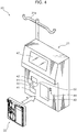
- Fig. 4 is a perspective view depicting a general configuration of the brain cooling apparatus according to an embodiment of the present invention.
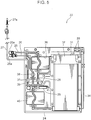
- Fig. 5 is a front view depicting a fluid filled unit of the cooling apparatus in Fig. 4 .
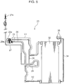
- Fig. 6 is a front view when the channel portion in Fig. 5 is enlarged.
- the brain cooling apparatus 20 has a fluid filled unit 22 that is connected to the brain cooling device 1, and an apparatus main unit 21 that circulates fluid filled in the fluid filled unit 22.
- the fluid filled unit 22 is able to be attached to/removed from the apparatus main unit 21, and is removed from the apparatus main unit 21 and disposed after being used for a specific patient.
- the fluid filled unit 22 has a channel member 23 (see Fig. 6 ) constituting a circulation route of the fluid for the brain cooling device 1, and a frame member 24 (see Fig. 5 ) which holds the channel member 23 in a predetermined form, and is attached to/removed from the apparatus main unit 21.
- the channel member 23 has a supply tube (supply channel) 26 that is connected to the injection tube 5 (see Fig. 1 ) of the brain cooling device 1, a collection tube (collection channel) 25 that is connected to the junction tube 9b of the brain cooling device 1, a storage tank (storage unit) 32 that is connected to the supply tube 26 and the collection tube 25, a bypass tube (bypass channel) 28 that connects the supply tube 26 and the collection tube 25, a detection tube 34 that connects an upper portion and a lower portion of the storage tank 32, an air vent filter 35 disposed on the detection tube 34, a filling tube 27 that is connected to an intermediate portion of the supply tube 26, and a temperature/pressure sensor 29 that is disposed in an intermediate portion of the supply tube 26.
- the supply tube 26 has an injection side connection tube 26a which can be attached to/removed from the injection side connector 6 of the brain cooling device 1.
- This supply tube 26 is disposed between the injection side connection unit 26a and the storage tank 32, as indicated by an arrow Y2 in Fig. 6 .
- the supply tube 26 is connected to the storage tank 32 at a position lower than the level of the fluid stored in the storage tank 32.
- the collection tube 25 has an ejection side connection unit 25a which can be attached to/removed from the ejection side connector 11 of the brain cooling device 1.
- the collection tube 25 is disposed between the ejection side connection unit 25a and the storage tank 32, as indicated by the arrow Y1 in Fig. 6 .
- the collection tube 25 is connected to the storage tank 32 at a position higher than the level of the fluid stored in the storage tank 32.
- the bypass tube 28 is connected to both tubes 25 and 26, so as to connect the intermediate portion of the supply tube 26 and the intermediate portion of the collection tube 25.
- the storage tank 32 is a container made of synthetic resin, that can be filled with 500 ml of physiological saline solution as the fluid. If the physiological saline solution is filled into the storage tank 32, the physiological saline fluid is injected into the detection tube 34 corresponding to the level of the physiological saline solution in the storage tank 32.
- the air vent filter 35 is provided for releasing the area inside the storage tank 32 into the air. In concrete terms, the air vent filter 35 allows gas to pass through, but interrupts the passing of liquid.
- the filling tube 27 is connected to the supply tube 26 at a position between the injection side connection unit 26a and the bypass tube 28.
- a piercing unit 27a that can pierce a port unit of a medicine bag containing physiological saline solution, is disposed on the edge of the filling tube 27.
- the temperature/pressure sensor 29 is disposed in an intermediate portion of the supply tube 26 located between the bypass tube 28 and the storage tank 32. This temperature/pressure sensor 29 can detect the temperature and pressure of the physiological saline solution in the supply tube 26, and can output an electric signal to indicate this detection value to the apparatus main unit 21.
- the frame member 24 is a plate member made of synthetic resin for holding the channel member 23 in the form shown in Fig. 6 .
- a tank hole 31 a pump hole 36, a pump hole 40, a valve hole 37, a valve hole 38 and a valve hole 39 are formed, penetrating from the front face to the rear face.
- the storage tank 32 is inserted into the tank hole 31. In other words, the storage tank 32 is held by the frame member 24 in a state where the front face and the rear face thereof are exposed.
- the pump hole 36 is disposed in a position where the collection tube 25 crosses vertically.
- the pump hole 40 is disposed in a position where the supply tube 26 crosses vertically.
- the valve hole 37 is disposed in a position where the filling tube 27 crosses vertically.
- the valve hole 38 is disposed in a position where the intermediate portion of the supply tube 26 crosses vertically.
- the valve hole 39 is disposed in a position where the intermediate portion of the bypass tube 28 crosses vertically.
- the apparatus main unit 21 has a first pump 41, a second pump 42, a cooling member 43, a level sensor 44, a first valve 50, a second valve 51, a third valve 52, an operation unit 47 and a control device (see Fig. 8 ) 48.
- the first pump 41 is for flowing the fluid inside the supply tube 26 along the supply tube 26.
- the first pump 41 is disposed in the pump hole 40 when the fluid filled unit 22 is attached to the apparatus main unit 21.
- the second pump 42 is for flowing the fluid inside the collection tube 25 along the collection tube 26.
- the second pump 42 is disposed in the pump hole 36 when the fluid filled unit 22 is attached to the apparatus main unit 21.
- the configuration of these pumps 41 and 42 will be described with reference to Fig. 7.
- Fig. 7 is a schematic diagram depicting the functions of the first pump 41 and the second pump 42 in Fig. 4 .
- the pump 41 or 42 has a tube support member 46, and a rotator 45 for pressing the tube by sandwiching the tube with the tube support member 46.
- the rotator 45 has a cross-shaped rotation frame 45a which has four arms, and a roller 45b which is disposed at the tip of each arm of the rotation frame 45a respectively.
- the rotation frame 45a can rotate around the axis J1.
- the roller 45b is supported by each arm rotatably around the axis J2 that is parallel with the axis J1, in a state of a part of the roller 45b protruding from the tip of the arm of the rotation frame 45a.
- the tube support member 46 has an arc-shaped groove of which center is located in the axis J1, and the tube is inserted along the inner side wall of this groove.
- the rotator 45 is disposed so that the tube is sandwiched between the tube support member 46 and the rotator 45. If the rotation frame 45a is driven and rotated around the axis J1 by a motor (not illustrated), the roller 45b rotates while maintaining the state of the tube being sandwiched between the roller 45b and the tube support member 46, whereby the fluid in the tube flows in the rotation direction. Since the roller 45b rotates while sandwiching the tube like this, the flow of the fluid in the tube is restricted when the rotation of the rotation frame 45a stops.
- the cooling member 43 closely contacts the storage tank 32 and cools the fluid in the storage tank 32.
- the cooling member 43 exerts the cooling capability according to the voltage to be applied, for which a Peletier element, for example, can be used.
- the cooling member 43 is disposed in a position that allows the cooling member 43 to closely contact the storage tank 32 when the fluid filled unit 22 is attached to the apparatus main unit 21.
- the apparatus main unit 21 has a cover that can be closed so as to sandwich the attached fluid filled unit 22, and a cooling member 43 is also disposed in the cover, although the cover is omitted in Fig. 4 .
- the level sensor 44 is for detecting the level of the fluid in the storage tank 32.
- the level sensor 44 is constituted by an infrared sensor, which is located at both side of the detection tube 34 so as to sandwich the detection tube 34 when the fluid filled unit 22 is attached to the apparatus main unit 21.
- the first valve 50 interrupts or releases the filling tube 27.
- the first valve 50 is disposed at both side of the filling tube 27 via the valve hole 37 so as to sandwich the filling tube 27 when the fluid filled unit 22 is attached to the apparatus main unit 21.
- the first valve 50 constricts the filling tube 27 as voltage is applied, and stops the constriction when voltage is not applied.
- the second valve 51 interrupts or releases the collection tube 25.
- the third valve 52 interrupts or releases the supply tube 26. Description of the second valve 51 and the third valve 52, which have a same configuration as the first valve 50, is omitted.
- the operation unit 47 has a role of a display unit for displaying operation state and other information, and a role of an operation unit for inputting various setting items to the later mentioned control device 48.
- the operation unit 47 can be constituted by a touch panel.
- Fig. 8 is a block diagram depicting an electric configuration of the control device 48 of the apparatus main unit 21 in Fig. 4 .
- the control device 48 controls the driving of the first valve 50 to the third valve 52, the first pump 41 and the second pump 42, and the cooling member 43 based on the input signals from the control unit 47, the level sensor 44, the temperature/pressure sensor 29 and the pressure sensors 7 and 10 (see Fig. 1 ).
- the control device 48 has a pump control unit 56 for controlling the driving of the first pump 41 and the second pump 42, a valve control unit 54 for controlling the driving of the first valve 50 to the third valve 52, and a temperature control unit 55 for adjusting the cooling capability by the cooling member 43.
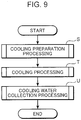
- Fig. 9 is a flow chart depicting a basic processing executed by the control device 48 in Fig. 8 .
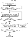
- Fig. 10 is a flow chart depicting the cooling preparation processing in Fig. 9 .
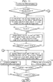
- Fig. 11 is a flow chart depicting the cooling processing in Fig. 9 .
- Fig. 12 is a flow chart depicting the pressure control processing in Fig. 11 .
- Fig. 13 is a flow chart depicting the cooling water collection processing in Fig. 9 .
- control device 48 sequentially executes the cooling preparation processing S, the cooling processing T and the cooling water collection processing U, as shown in Fig. 9 .
- a medical staff Before executing the cooling preparation processing S, a medical staff performs the following preparation.
- the medical staff attaches the fluid filled unit 22 to the apparatus main unit 21 as illustrated in Fig. 4 , and uses the piercing portion 27a (see Fig. 5 ) of the fluid filled unit 22 to pierce a port of the bag (not illustrated) filled with physiological saline solution.
- the medical staff hangs the bag onto a hanging hook 21a of the apparatus main unit.
- step S1 it is determined whether the medical staff operated an operation preparation button displayed on the operation unit 47 (step S1), and if it is determined that the operation preparation button was not operated, step S1 is repeatedly executed.
- step S2 filling of the physiological saline solution into the storage tank 32 is started in step S2.
- the filling tube 27 is opened by the first valve 50, and the supply tube 26 and the collection tube 25 are interrupted by the second valve 51 and the third valve 52.
- the first pump 41 is driven in a direction of the physiological saline solution flowing toward the storage tank 32.
- the physiological saline solution in the bag is guided to the storage tank 32 via the filling tube 27 and the supply tube 26.
- step S3 it is determined whether the level of the physiological saline solution in the storage tank 32 is the preset highest level by the level sensor 44 (step S3), and if it is determined that the level is not the highest level, step S2 is repeated.
- step S4 If it is determined that the level of the physiological saline solution in the storage tank 32 is the highest level in step S3, cooling of the physiological saline solution in the storage tank 32 is started in step S4.
- the filling tube 27 and the supply tube 26 are interrupted by the first valve 50 and the second valve 51, and the bypass tube 28 is opened by the third valve 52.
- the first pump 41 is driven in the direction of the physiological saline solution being sucked from the storage tank 32, and voltage is applied to the cooling member 43 (see Fig. 8 ).
- step S5 it is determined whether the temperature of the physiological saline solution detected by the temperature/pressure sensor 29 is a target temperature. If it is determined that the temperature of the physiological saline solution is not the target temperature, the temperature of the cooling member 43 is controlled (step S6). Specifically, in step S6, if the temperature of the physiological saline solution is higher than the target temperature, the voltage to be applied to the cooling member 43 is increased to increase the cooling capability of the cooling member 43. If the temperature of the physiological saline solution is lower than the target temperature, the voltage to be applied to the cooling member 43 is decreased to decrease the cooling capability of the cooling member 43.
- step S6 If it is determined that the temperature of the physiological saline solution is the target temperature in step S6, then processing returns to the main routine in Fig. 9 , and the cooling processing T in Fig. 11 is executed.
- the medical staff Prior to the execution of this cooling processing T, the medical staff connects the injection side connector 6 of the brain cooling device 1 in Fig. 1 to the injection side connection unit 26a of the fluid filled unit 22 in Fig. 5 , and connects the ejection side connector 11 of the brain cooling device 1 in Fig. 1 to the ejection side connection unit 25a of the fluid filled unit 22 in Fig. 5 . These connections may be made via predetermined extension tubes between the brain cooling device 1 and the fluid filled unit 22.
- step T1 it is determined whether the medical staff operated a cooling start button displayed on the operation unit 47 (step T1). If it is determined that the cooling start button was not operated, step S4 is repeatedly executed.
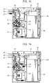
- step T1 filling of the physiological saline solution into the brain cooling device 1 is started in step T2.
- the filling tube 27 and the bypass tube 28 are interrupted by the first valve 50 and the third valve 52, and the supply tube 26 is opened by the second valve 51.
- the first pump 41 is driven in a direction of the physiological saline solution being sucked from the storage tank 32, and the second pump 42 is driven so that a flow toward the storage tank 32 is generated.
- the physiological saline solution in the storage tank 32 is supplied to the brain cooling device 1 via the supply tube 26, and excessive physiological saline that cannot be contained in the brain cooling device 1 is collected in the storage tank 32 via the collection tube 25.
- Fig. 14 is a graph depicting a transition of the rotation speed of each pump and the pressure detected by the pressure sensor 10 in the cooling preparation processing S and the cooling processing T.
- the solid line indicates the rotation speed of the first pump 41
- the broken line is the rotation speed of the second pump 42
- the dashed-dotted line is the pressure detected by the pressure sensor 10.
- step T2 it is confirmed experimentally that the pressure detected by the pressure sensor 10 drops to about 1 kPa if the air in the brain cooling device 1 is replaced with the physiological saline solution. Therefore in step T2, it is determined whether the physiological saline solution is filled into the brain cooling device 1 depending on whether the pressure detected by the pressure sensor 10 dropped. If it is determined that the physiological saline solution is not filled in step T2, step T2 is repeatedly executed.
- the physiological saline solution is replenished from the bag containing the physiological saline solution to the storage tank 32 in step T4.
- the first valve 50 is set to the open state and the second valve 51 and the third valve 52 are set to the close state, and the first pump 41 is driven in a direction of generating the flow to the storage tank 32. Thereby the physiological saline solution is guided from the bag toward the storage tank 32.
- step T5 it is determined whether the level of the physiological saline solution in the storage tank 32 is the highest level. If it is determined that the level is not the highest level, step T4 is repeatedly executed.
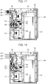
- step T6 circulation of the physiological saline solution between the storage tank 32 and the water cooling device 1 is started, as shown in Fig. 17 (step T6).
- step T6 the filling tube 27 and the bypass tube 28 are interrupted by the first valve 50 and the third valve 52, and the supply tube 26 is opened by the second valve 51.
- the first pump 41 is driven in a direction of sucking the physiological saline solution from the storage tank 32
- the second pump 42 is driven in a direction of collecting the physiological saline solution in the storage tank 32.
- step T7 it is determined whether the pressure of the physiological saline solution in the brain cooling device 1 detected by the pressure sensor 10 is a preset target pressure (e.g. 5 kPa) (step T7). If it is determined that the pressure detected by the pressure sensor 10 is not the target pressure, the pressure control processing T10 is executed.
- the target pressure may be a specific numerical value, but may also be set as a predetermined range.
- Fig. 12 is a flow chart depicting the content of the pressure control processing T10 in Fig. 11 .
- Fig. 12 shows, when the pressure control processing T10 is started, it is determined whether the pressure detected by the pressure sensor 10 is higher than the target pressure (step T11). If the pressure detected by the pressure sensor 10 is higher than the target pressure, the rotation speed of the second pump 42 is increased (step T12). If the pressure detected by the pressure sensor 10 is lower than the target pressure, the rotation speed of the second pump 42 is decreased (step T13). In other words, according to the cooling processing of this embodiment, the rotation speed of the second pump 42 is increased when the pressure detected by the pressure sensor 10 exceeds the target pressure, and the rotation speed of the second pump 42 is decreased when the pressure detected by the pressure sensor 10 does not reach the target pressure, while keeping the rotation speed of the first pump 41 approximately constant, as shown in Fig. 14 . The flow rate of the physiological saline solution to the brain cooling device 1 is determined by the rotation speed of the first pump 41.
- step T8 it is determined whether the temperature of the physiological saline solution detected by the temperature/pressure sensor 29 is a preset target temperature (step T8).
- Fig. 13 is a flow chart depicting the cooling water collection processing in Fig. 9 .
- step U1 it is determined whether the medical staff operated a cooling water collection button displayed on the operation unit 47 (step U1). If it is determined that the cooling water collection button was not operated, step T6 is repeatedly executed.
- step U1 the physiological saline solution in the storage tank 32 is collected in step U2.
- the supply tube 26 and the bypass tube 28 are interrupted by the second valve 51 and the third valve 52, and the filling tube 27 is opened by the first valve 50.
- the first pump 41 is driven in the direction of physiological saline solution being sucked from the storage tank 32.
- the physiological saline solution in the storage tank 32 is collected in the bag connected to the filling tube 27 via the supply tube 26 and the filling tube 27.
- step U3 it is determined whether all physiological saline solution in the storage tank 32 is collected (step U3), and if it is determined that all physiological saline solution is not collected, step U2 is repeatedly executed. Whether all physiological saline solution in the storage tank 32 is collected or not can be determined based on the change of the pressure detected by the temperature/pressure sensor 29.
- the remaining physiological saline solution in the brain cooling device 1 is collected in the storage tank 32 in step U4.
- the filling tube 27 and the bypass tube 28 are interrupted by the first valve 50 and the third valve 52, and the supply tube 26 is opened by the second valve 51.
- the first pump 41 is driven in the direction of generating the flow toward the storage tank 32
- the second pump 42 is driven in the direction of sucking the fluid from the storage tank 32.
- the physiological saline solution in the brain cooling device 1 is collected in the storage tank 32 via the supply tube 26, and the air in the storage tank 32 is guided to the brain cooling device 1 via the collection tube 25.
- step U4 is executed until the predetermined time elapses in step U5
- the physiological saline solution in the storage tank 32 is collected in the bag until all physiological saline solution in the storage tank 32 is collected in the same manner as in steps U2 and U3 (steps U6 and U7), and this processing ends.
- the rotation speed of the second pump 42 is adjusted so that the pressure in the cuff 4 of the brain cooling device 1 becomes the target pressure. Therefore while maintaining the pressure of the physiological saline solution in the cuff 4 at around the target pressure, the physiological saline can be circulated between the cuff 4 and the storage tank 32.
- the driving speed of the second pump 42 which drives in the direction of sucking the physiological saline solution from the cuff 4 upon circulating the physiological saline solution, can be adjusted.
- the pressure of the physiological saline solution in the cuff 4 becomes unnecessarily high, the pressure can be maintained as mentioned above, while suppressing load applied to the cuff 4 and the wall of the esophagus with which the cuff 4 closely contacts.
- the pressure sensor 10 is disposed on the brain cooling device 1 side.
- the distance between the pressure sensor and the cuff 4 can be decreased more than a distance between the pressure sensor and the cuff 4 in the case of disposing the pressure sensor on the brain cooling apparatus 20 side. Since this allows detecting the pressure of the physiological saline solution in the cuff 4 more accurately, the pressure of the physiological saline solution in the cuff 4 can be closer to the target pressure at higher precision if at least the rotation speed of the second pump 42 is adjusted based on this detection result.
- the pressure of the physiological saline solution in the cuff 4 can be detected fairly accurately by simply disposing the pressure sensor in a position close to the brain cooling device 1 (e.g. near the ejection side connection unit 25a in Fig. 5 ).
- the pressure sensor may be disposed on the brain cooling apparatus 20 side.
- the rotation speed of the second pump 42 is controlled based on the pressure detected by the pressure sensor 10.
- the rotation speed of the second pump 42 may also be controlled based on the pressure detected by the pressure sensor 7.
- the rotation speed of the second pump 42 is adjusted, while keeping the rotation speed of the first pump 41 constant. Thereby the difference between the rotation speed of the first pump 41 and that of the second pump 42 can be easily adjusted. Since the rotation speed of the first pump 41, which specifies the flow rate of the physiological saline solution to the cuff 4, is constant, the pressure of the physiological saline solution in the cuff 4 can also be maintained approximately at a constant level, while keeping the flow rate of the physiological saline solution to the cuff 4 at a constant level.
- Fig. 20 is a flow chart depicting a processing executed by a control device according to another embodiment of the present invention.
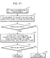
- Fig. 21 is a flow chart depicting a processing executed in the tube confirmation processing in Fig. 20 .
- Fig. 22 and Fig. 23 are front views depicting an operation of the apparatus main unit according to an embodiment of the present invention.
- a composing element the same as the previous embodiment is denoted with a same reference symbol, for which redundant description is omitted.
- the tube confirmation processing V is executed in addition to the above processing executed in this embodiment.
- the tube confirmation processing V it is confirmed whether the supply tube 26 and the collection tube 25 of the channel member 23 are perfectly attached to the first pump 41 and the second pump 42.
- the apparatus main unit 21 of this embodiment has a fourth valve 53, in addition to the above mentioned first valve 50 to the third valve 52.
- the fourth valve 53 is for interrupting or opening the collection tube 25 at a portion of the collection tube 25 that is closer to the storage tank 32 than a branch point of the bypass tube 28.
- a valve hole (not illustrated) for the fourth valve 53, to penetrate through, is provided in the frame member 24.
- the control device 48 controls driving of the fourth valve 53.
- Fig. 20 shows, if it is determined that the operation button is operated in the cooling preparation processing S (YES in step S1), the tube confirmation processing V is executed. If it is determined that the water level is not the highest level in step S3 (NO in step S3), processing returns to step S2, instead of executing the tube confirmation processing V.
- step V1 the first pump 41 is driven in a state where the air in the supply tube 26 can go nowhere, whereby the air in the storage tank 32 is sent to the supply tube 26.
- step V2 it is determined whether the pressure detected by the pressure sensor 29 has risen to a predetermined value by driving of the first pump 41 (step V2). In other words, in step V2, it is determined whether a state where the pressure in the supply tube 26 does not rise, even though the first pump 41 is driven, has occurred. In other words, it is determined whether a state where air is not injected into the supply tube 26, because the supply tube 26 is not accurately attached to the first pump 41, has occurred.
- step V2 If a rise in pressure is not detected in step V2 (NO in step V2), an error processing V5 is performed assuming that the supply tube 26 is not accurately attached to the first pump 41, then processing advances according to the response of the error processing V5.
- the error processing V5 the first valve 50 to the fourth valve 53 are opened, and driving the first pump 41 is stopped. Further in the error processing V5, after it is displayed or notified that the supply tube 26 is not accurately attached to the first pump 41 by using the operation unit 47, processing stands by until the medical staff performs the input operation for confirmation.
- step V3 If a rise in the pressure is detected in step V2 (YES in step V2), operation to confirm whether the collection tube 25 is accurately attached to the second pump 42 is executed in step V3.
- the first valve 50, the second valve 51 and the fourth valve 53 are closed, as illustrated in Fig. 23 , and the third valve 52 is opened.
- the second pump 42 is driven toward the collection side after the first pump 41 is stopped. In other words, in step V3, the second pump 42 is driven in a state where the air injected into the supply tube 26 via the collection tube 25 and the bypass tube 28 can go nowhere, whereby the air injected via the collection tube 25 is sent to the supply tube 26.
- step V4 it is determined whether the pressure detected by the pressure sensor 29 has risen to a predetermined value by driving of the second pump 42 (step V4). In other words, in step V4, it is determined whether a state, where the pressure in the supply tube 26 does not rise even thought the second pump 42 is driven, has occurred. In other words, in step V4, it is determined whether a state, where air is not injected into the supply tube 26 because the collection tube 25 is not accurately attached to the second pump 42, has occurred.
- step V4 If a rise in the pressure is not detected in step V4 (NO in step V4), the error processing V5 is performed assuming that the collection tube 25 is not accurately attached to the second pump 42, then processing advances according to the result of the error processing V5.
- step V4 If a rise in the pressure is detected in step V4 (YES in step V4), processing returns to the above mentioned step S2, as shown in Fig. 20 .
Landscapes
- Health & Medical Sciences (AREA)
- Pulmonology (AREA)
- Veterinary Medicine (AREA)
- Animal Behavior & Ethology (AREA)
- Public Health (AREA)
- Biomedical Technology (AREA)
- Heart & Thoracic Surgery (AREA)
- General Health & Medical Sciences (AREA)
- Life Sciences & Earth Sciences (AREA)
- Engineering & Computer Science (AREA)
- Anesthesiology (AREA)
- Hematology (AREA)
- Emergency Medicine (AREA)
- Vascular Medicine (AREA)
- Physics & Mathematics (AREA)
- Thermal Sciences (AREA)
- Thermotherapy And Cooling Therapy Devices (AREA)
- Surgical Instruments (AREA)
Claims (5)
- Gehirnkühlungssystem, umfassend eine Gehirnkühlungsvorrichtung (1) und eine Gehirnkühlungseinrichtung (20), wobei
die Gehimkühlungsvorrichtung (1) umfasst:eine fassende Einheit (4), die durch ein hinein injiziertes Fluid aufgeweitet werden kann und mindestens einen Teil eines Bereichs von einer Mundhöhle zu einem Magen eines lebenden Körpers nah berühren kann, in einem Zustand des oralen oder transnasalen Eingeführtwerdens in den lebenden Körper;eine Injektionseinheit (2), die Fluid von außerhalb des Körpers in die fassende Einheit (4) injizieren kann und an eine injektionsseitige Anschlusseinheit (26a) der Gehirnkühlungseinrichtung (20) angeschlossen werden kann;eine Ausstoßeinheit (3), die das Fluid in der fassenden Einheit (4) aus dem Körper hinaus ausstoßen kann und an eine ausstoßseitige Anschlusseinheit (25a) der Gehirnkühlungseinrichtung (20) angeschlossen werden kann; undeine Detektionseinheit (10), die einen Druck des Fluids in der Injektionseinheit (2) oder der Ausstoßeinheit (3) erkennen kann und das Detektionsergebnis an eine Steuer- bzw. Regeleinheit (48) der Gehirnkühlungseinrichtung (20) ausgeben kann, unddie Gehirnkühlungseinrichtung (20) umfasst:die injektionsseitige Anschlusseinheit (26a), die mit der Injektionseinheit (2) verbunden werden kann;die ausstoßseitige Anschlusseinheit (25a), die mit der Ausstoßeinheit (3) verbunden werden kann;eine Speichereinheit (32), die das Fluid speichert;einen Versorgungskanal (26), der die Speichereinheit (32) und die injektionsseitige Anschlusseinheit (26a) verbindet;einen Sammelkanal (25), der die Speichereinheit (32) und die ausstoßseitige Anschlusseinheit (25a) verbindet;eine erste Pumpe (41), die auf dem Versorgungskanal (26) angeordnet ist, um das Fluid entlang des Versorgungskanals (26) strömen zu lassen;eine zweite Pumpe (42), die auf dem Sammelkanal (25) angeordnet ist, um das Fluid entlang des Sammelkanals (25) strömen zu lassen; undeine Steuer- bzw. Regeleinheit (48), die den Antrieb der ersten Pumpe (41) und der zweiten Pumpe (42) steuert bzw. regelt, wobeidie Steuer- bzw. Regeleinheit (48) eine Antriebsgeschwindigkeit der zweiten Pumpe (42) so einstellt, dass ein Druck in der fassenden Einheit (4) ein voreingestellter Zieldruck in einem Zustand des Zirkulierens des Fluids zwischen der Speichereinheit (32) und der fassenden Einheit (4) wird, indem die erste Pumpe (41) so angetrieben wird, dass das Fluid in einer Richtung von der Speichereinheit (32) zu der fassenden Einheit (4) strömt, und indem die zweite Pumpe (42) so angetrieben wird, dass das Fluid in einer Richtung von der fassenden Einheit (4) zu der Speichereinheit (32) strömt, unddie Steuer- bzw. Regeleinheit (48) die Antriebsgeschwindigkeit der zweiten Pumpe (42) so einstellt, dass sie erhöht wird, wenn der Druck in der fassenden Einheit (4), der von der Detektionseinheit (10) erkannt wird, höher ist als der Zieldruck, während die Drehzahl der ersten Pumpe (41) konstant gehalten wird, und die Antriebsgeschwindigkeit der zweiten Pumpe (42) so einstellt, dass sie verringert wird, wenn der Druck in der fassenden Einheit (4), der von der Detektionseinheit (10) erkannt wird, niedriger ist als der Zieldruck, während die Drehzahl der ersten Pumpe (41) konstant gehalten wird. - Gehirnkühlungssystem nach Anspruch 1, wobei
die Steuer- bzw. Regeleinheit (48) die Antriebsgeschwindigkeit der ersten Pumpe (41) so einstellt, dass sie konstant ist, und die Antriebsgeschwindigkeit der zweiten Pumpe (42) so einstellt, dass der Druck in der fassenden Einheit (4) der Zieldruck wird, in einem Zustand des Fluids, das zwischen der Speichereinheit (32) und der fassenden Einheit (4) zirkuliert. - Gehirnkühlungssystem nach einem der Ansprüche 1 oder 2, ferner umfassend eine Kühleinheit (43) zum Kühlen des Fluids in der Speichereinheit (32), wobei
die Steuer- bzw. Regeleinheit (48) eine Kühlleistung der Kühleinheit (43) so einstellt, dass eine Temperatur des Fluids in der Speichereinheit (32) eine voreingestellte Zieltemperatur wird. - Gehirnkühlungssystem nach Anspruch 3, ferner umfassend:einen Bypass-Kanal (28), der einen Zwischenabschnitt des Versorgungskanals (26), der sich in einer gegenüberliegenden Position von der Speichereinheit (32) in Bezug auf die erste Pumpe (41) befindet, und einen Zwischenabschnitt des Sammelkanals (25) verbindet, der sich in einer Position zwischen der zweiten Pumpe (42) und der Speichereinheit (32) befindet; undein Ventil (52), das den Versorgungskanal (26) an einer Position unterbrechen kann, die der injektionsseitigen Anschlusseinheit (26a) näher ist als dem Bypass-Kanal (28), wobeidie zweite Pumpe (42) den Sammelkanal (25) unterbricht, wenn die zweite Pumpe (42) in einem Stoppzustand ist, unddie Steuer- bzw. Regeleinheit (48) den Sammelkanal (26) unter Verwendung des Ventils (52) unterbricht, die zweite Pumpe (42) stoppt und die erste Pumpe (41) antreibt in einer Phase vor dem Starten der Fluidzirkulation, um dadurch das Fluid in der Speichereinheit (32) zu der Speichereinheit (32) über den Sammelkanal (25), den Bypass-Kanal (28) und den Versorgungskanal (26) zurückzuführen.
- Gehirnkühlungssystem nach einem der Ansprüche 1 bis 4, wobei
das Fluid flüssig ist,
der Versorgungskanal (26) an die Speichereinheit (32) an einer Position angeschlossen ist, die niedriger ist als ein Pegel der Flüssigkeit in der Speichereinheit (32), und der Sammelkanal (25) an die Speichereinheit (32) an einer Position angeschlossen ist, die höher ist als der Pegel der Flüssigkeit in der Speichereinheit (32), und in einer Phase, nachdem die Flüssigkeitszirkulation endet, die Steuer- bzw. Regeleinheit (48) die zweite Pumpe (42) in einer Richtung antreibt, in der die Flüssigkeit in dem Sammelkanal (25) zu der fassenden Einheit (4) strömt, und die erste Pumpe (41) in einer Richtung antreibt, in der die Flüssigkeit in dem Versorgungskanal (26) zu der Speichereinheit (32) strömt.
Applications Claiming Priority (2)
| Application Number | Priority Date | Filing Date | Title |
|---|---|---|---|
| JP2010036374A JP5468414B2 (ja) | 2010-02-22 | 2010-02-22 | 脳冷却装置及びこれに適した脳冷却用具 |
| PCT/JP2011/000947 WO2011102146A1 (ja) | 2010-02-22 | 2011-02-21 | 脳冷却装置及びこれに適した脳冷却用具 |
Publications (3)
| Publication Number | Publication Date |
|---|---|
| EP2540260A1 EP2540260A1 (de) | 2013-01-02 |
| EP2540260A4 EP2540260A4 (de) | 2015-02-18 |
| EP2540260B1 true EP2540260B1 (de) | 2020-08-12 |
Family
ID=44482751
Family Applications (1)
| Application Number | Title | Priority Date | Filing Date |
|---|---|---|---|
| EP11744437.2A Not-in-force EP2540260B1 (de) | 2010-02-22 | 2011-02-21 | Gehirnkühlungsvorrichtung und dazu gehörendes gehirnkühlungsgerät |
Country Status (4)
| Country | Link |
|---|---|
| US (1) | US9522244B2 (de) |
| EP (1) | EP2540260B1 (de) |
| JP (1) | JP5468414B2 (de) |
| WO (1) | WO2011102146A1 (de) |
Families Citing this family (13)
| Publication number | Priority date | Publication date | Assignee | Title |
|---|---|---|---|---|
| US10271889B2 (en) | 2010-06-27 | 2019-04-30 | Sunnybrook Health Sciences Centre | Apparatus and method for cooling a tissue volume during thermal therapy treatment |
| JP2014529315A (ja) | 2011-07-25 | 2014-11-06 | ニューロセーブ インコーポレイテッド | 選択的脳冷却のための非侵襲的なシステム、機器、および方法 |
| US9101344B2 (en) | 2013-03-15 | 2015-08-11 | Covidien Lp | Recirculating cooling system for energy delivery device |
| US9682190B2 (en) * | 2013-03-15 | 2017-06-20 | Covidien Lp | Recirculating cooling system for energy delivery device |
| EP2860399A1 (de) * | 2013-10-14 | 2015-04-15 | ECP Entwicklungsgesellschaft mbH | Verfahren zum Betrieb einer Versorgungseinrichtung, die einen Kanal mit einer Flüssigkeit beaufschlagt, sowie Versorgungseinrichtung |
| CN104288896B (zh) * | 2014-06-25 | 2017-11-14 | 首都医科大学 | 一种颅脑灌注降温便携箱 |
| WO2016110788A2 (en) * | 2015-01-05 | 2016-07-14 | Profound Medical Inc. | Endocavity temperature control device |
| US20170157366A1 (en) * | 2015-12-03 | 2017-06-08 | Benny Assif | Urinary catheters, systems and methods for use during treatment of the prostate |
| US11071586B2 (en) | 2017-06-05 | 2021-07-27 | Covidien Lp | Cooling systems for energy delivery devices |
| KR101840346B1 (ko) * | 2017-08-08 | 2018-05-04 | 주식회사 비엠텍월드와이드 | 냉각 기체 회수 장치를 갖는 극저온 치료기 및 이의 제어방법 |
| JP2023062765A (ja) * | 2021-10-22 | 2023-05-09 | 大研医器株式会社 | 冷却装置、冷却ユニット、および頭部装着冷却セット |
| CN119184953A (zh) * | 2023-05-31 | 2024-12-27 | 南京医科大学 | 一种脑室内使用降温系统 |
| JP7481061B1 (ja) | 2024-01-09 | 2024-05-10 | 義成 濱▲崎▼ | ラリンジアルマスク及びラリンジアルマスクの装着方法 |
Family Cites Families (13)
| Publication number | Priority date | Publication date | Assignee | Title |
|---|---|---|---|---|
| US6149624A (en) * | 1998-02-05 | 2000-11-21 | Mcshane; Richard Houston | Apparatus and method for the rapid induction of hypothermic brain preservation |
| JP4474590B2 (ja) * | 2002-06-17 | 2010-06-09 | 厚夫 森 | 局所冷却カテーテルおよびそれを用いた局所冷却デバイス |
| US7666213B2 (en) * | 2002-07-11 | 2010-02-23 | Life Recovery Systems Hd, Llc | Apparatus for altering the body temperature of a patient |
| CA2411569A1 (en) * | 2002-11-12 | 2004-05-12 | Ross E. Mantle | Medical device for the extravascular recirculation of fluid in body cavities at controlled temperature and pressure |
| US7758623B2 (en) * | 2003-03-17 | 2010-07-20 | The Board Of Trustees Of The Leland Stanford Junior University | Transesophageal heat exchange catheter for cooling of the heart |
| US7189253B2 (en) * | 2004-03-16 | 2007-03-13 | Quickcool Ab | Cerebral temperature control |
| JP3702295B1 (ja) * | 2004-03-31 | 2005-10-05 | 国立大学法人 岡山大学 | 脳の冷却装置及びこれに用いる流体注入装置 |
| JP4658758B2 (ja) * | 2005-09-16 | 2011-03-23 | 国立大学法人 岡山大学 | 脳の冷却用具及びこれを備えた脳の冷却装置 |
| AU2009206271B8 (en) * | 2008-01-25 | 2013-04-11 | Neurosave, Inc, | Rapid cooling of body and/or brain by irrigating with a cooling liquid |
| US20090234325A1 (en) * | 2008-03-17 | 2009-09-17 | Allan Rozenberg | Methods and devices for non-invasive cerebral and systemic cooling |
| AU2010210385A1 (en) * | 2009-02-06 | 2011-08-18 | Velomedix, Inc. | Method and apparatus for inducing therapeutic hypothermia |
| US9980765B2 (en) * | 2010-02-15 | 2018-05-29 | The General Hospital Corporation | Methods and devices for selective disruption of visceral fat by controlled cooling |
| JP2014529315A (ja) * | 2011-07-25 | 2014-11-06 | ニューロセーブ インコーポレイテッド | 選択的脳冷却のための非侵襲的なシステム、機器、および方法 |
-
2010
- 2010-02-22 JP JP2010036374A patent/JP5468414B2/ja not_active Expired - Fee Related
-
2011
- 2011-02-21 WO PCT/JP2011/000947 patent/WO2011102146A1/ja not_active Ceased
- 2011-02-21 EP EP11744437.2A patent/EP2540260B1/de not_active Not-in-force
- 2011-02-21 US US13/580,394 patent/US9522244B2/en not_active Expired - Fee Related
Non-Patent Citations (1)
| Title |
|---|
| None * |
Also Published As
| Publication number | Publication date |
|---|---|
| JP2011167461A (ja) | 2011-09-01 |
| JP5468414B2 (ja) | 2014-04-09 |
| WO2011102146A1 (ja) | 2011-08-25 |
| EP2540260A1 (de) | 2013-01-02 |
| US20120323296A1 (en) | 2012-12-20 |
| EP2540260A4 (de) | 2015-02-18 |
| US9522244B2 (en) | 2016-12-20 |
Similar Documents
| Publication | Publication Date | Title |
|---|---|---|
| US9522244B2 (en) | Brain cooling apparatus and brain cooling device suitable thereto | |
| US8672884B2 (en) | Method and apparatus for peritoneal hypothermia and/or resuscitation | |
| US5730720A (en) | Perfusion hyperthermia treatment system and method | |
| US20140031631A1 (en) | Method and Apparatus for Inducing Therapeutic Hypothermia | |
| US11446177B2 (en) | Method and apparatus for peritoneal oxygenation | |
| US10569002B2 (en) | Portable medical apparatus for cardiopulmonary aid to patients | |
| US20020161349A1 (en) | Cerebral temperature control | |
| JP2003524474A (ja) | 中断されないフローポンプ装置および方法 | |
| CN116439871B (zh) | 一种用于动物的ecmo实验装置及其方法 | |
| ES3015545T3 (en) | Microplegia delivery system | |
| CA2476382A1 (en) | Cerebral temperature control | |
| JPH0380028B2 (de) | ||
| CN120884426A (zh) | 一种基于双腔道精准控温的创伤患者体腔复温方法、装置及存储介质 | |
| CN120225231A (zh) | 使用流体交换导管操控身体特性的系统和方法 | |
| KR20230173991A (ko) | 수술환자를 위한 이중관 수액 온도 유지장치 | |
| US20250144334A1 (en) | Liquid Ventilation System | |
| AU2013205065A1 (en) | Method and apparatus for peritoneal hypothermia and/or resuscitation |
Legal Events
| Date | Code | Title | Description |
|---|---|---|---|
| PUAI | Public reference made under article 153(3) epc to a published international application that has entered the european phase |
Free format text: ORIGINAL CODE: 0009012 |
|
| 17P | Request for examination filed |
Effective date: 20120920 |
|
| AK | Designated contracting states |
Kind code of ref document: A1 Designated state(s): AL AT BE BG CH CY CZ DE DK EE ES FI FR GB GR HR HU IE IS IT LI LT LU LV MC MK MT NL NO PL PT RO RS SE SI SK SM TR |
|
| A4 | Supplementary search report drawn up and despatched |
Effective date: 20150119 |
|
| RIC1 | Information provided on ipc code assigned before grant |
Ipc: A61B 19/00 20060101ALN20150113BHEP Ipc: A61F 7/10 20060101ALI20150113BHEP Ipc: A61M 16/04 20060101ALI20150113BHEP Ipc: A61F 7/12 20060101AFI20150113BHEP Ipc: A61B 17/00 20060101ALI20150113BHEP Ipc: A61F 7/00 20060101ALN20150113BHEP |
|
| STAA | Information on the status of an ep patent application or granted ep patent |
Free format text: STATUS: EXAMINATION IS IN PROGRESS |
|
| 17Q | First examination report despatched |
Effective date: 20180319 |
|
| RAP1 | Party data changed (applicant data changed or rights of an application transferred) |
Owner name: NATIONAL UNIVERSITY CORPORATION OKAYAMA UNIVERSITY Owner name: DAIKIN IKI KABUSHIKI KAISHA |
|
| GRAP | Despatch of communication of intention to grant a patent |
Free format text: ORIGINAL CODE: EPIDOSNIGR1 |
|
| STAA | Information on the status of an ep patent application or granted ep patent |
Free format text: STATUS: GRANT OF PATENT IS INTENDED |
|
| RIC1 | Information provided on ipc code assigned before grant |
Ipc: A61M 16/04 20060101ALI20200313BHEP Ipc: A61F 7/00 20060101ALN20200313BHEP Ipc: A61F 7/10 20060101ALI20200313BHEP Ipc: A61B 17/00 20060101ALI20200313BHEP Ipc: A61F 7/12 20060101AFI20200313BHEP |
|
| INTG | Intention to grant announced |
Effective date: 20200403 |
|
| RIC1 | Information provided on ipc code assigned before grant |
Ipc: A61B 17/00 20060101ALI20200325BHEP Ipc: A61M 16/04 20060101ALI20200325BHEP Ipc: A61F 7/00 20060101ALN20200325BHEP Ipc: A61F 7/12 20060101AFI20200325BHEP Ipc: A61F 7/10 20060101ALI20200325BHEP |
|
| GRAS | Grant fee paid |
Free format text: ORIGINAL CODE: EPIDOSNIGR3 |
|
| GRAA | (expected) grant |
Free format text: ORIGINAL CODE: 0009210 |
|
| STAA | Information on the status of an ep patent application or granted ep patent |
Free format text: STATUS: THE PATENT HAS BEEN GRANTED |
|
| AK | Designated contracting states |
Kind code of ref document: B1 Designated state(s): AL AT BE BG CH CY CZ DE DK EE ES FI FR GB GR HR HU IE IS IT LI LT LU LV MC MK MT NL NO PL PT RO RS SE SI SK SM TR |
|
| REG | Reference to a national code |
Ref country code: GB Ref legal event code: FG4D |
|
| REG | Reference to a national code |
Ref country code: CH Ref legal event code: EP |
|
| REG | Reference to a national code |
Ref country code: IE Ref legal event code: FG4D |
|
| REG | Reference to a national code |
Ref country code: DE Ref legal event code: R096 Ref document number: 602011068186 Country of ref document: DE |
|
| REG | Reference to a national code |
Ref country code: AT Ref legal event code: REF Ref document number: 1300792 Country of ref document: AT Kind code of ref document: T Effective date: 20200915 |
|
| REG | Reference to a national code |
Ref country code: LT Ref legal event code: MG4D |
|
| REG | Reference to a national code |
Ref country code: NL Ref legal event code: MP Effective date: 20200812 |
|
| PG25 | Lapsed in a contracting state [announced via postgrant information from national office to epo] |
Ref country code: LT Free format text: LAPSE BECAUSE OF FAILURE TO SUBMIT A TRANSLATION OF THE DESCRIPTION OR TO PAY THE FEE WITHIN THE PRESCRIBED TIME-LIMIT Effective date: 20200812 Ref country code: HR Free format text: LAPSE BECAUSE OF FAILURE TO SUBMIT A TRANSLATION OF THE DESCRIPTION OR TO PAY THE FEE WITHIN THE PRESCRIBED TIME-LIMIT Effective date: 20200812 Ref country code: FI Free format text: LAPSE BECAUSE OF FAILURE TO SUBMIT A TRANSLATION OF THE DESCRIPTION OR TO PAY THE FEE WITHIN THE PRESCRIBED TIME-LIMIT Effective date: 20200812 Ref country code: GR Free format text: LAPSE BECAUSE OF FAILURE TO SUBMIT A TRANSLATION OF THE DESCRIPTION OR TO PAY THE FEE WITHIN THE PRESCRIBED TIME-LIMIT Effective date: 20201113 Ref country code: NO Free format text: LAPSE BECAUSE OF FAILURE TO SUBMIT A TRANSLATION OF THE DESCRIPTION OR TO PAY THE FEE WITHIN THE PRESCRIBED TIME-LIMIT Effective date: 20201112 Ref country code: SE Free format text: LAPSE BECAUSE OF FAILURE TO SUBMIT A TRANSLATION OF THE DESCRIPTION OR TO PAY THE FEE WITHIN THE PRESCRIBED TIME-LIMIT Effective date: 20200812 Ref country code: BG Free format text: LAPSE BECAUSE OF FAILURE TO SUBMIT A TRANSLATION OF THE DESCRIPTION OR TO PAY THE FEE WITHIN THE PRESCRIBED TIME-LIMIT Effective date: 20201112 Ref country code: ES Free format text: LAPSE BECAUSE OF FAILURE TO SUBMIT A TRANSLATION OF THE DESCRIPTION OR TO PAY THE FEE WITHIN THE PRESCRIBED TIME-LIMIT Effective date: 20200812 |
|
| REG | Reference to a national code |
Ref country code: AT Ref legal event code: MK05 Ref document number: 1300792 Country of ref document: AT Kind code of ref document: T Effective date: 20200812 |
|
| PG25 | Lapsed in a contracting state [announced via postgrant information from national office to epo] |
Ref country code: IS Free format text: LAPSE BECAUSE OF FAILURE TO SUBMIT A TRANSLATION OF THE DESCRIPTION OR TO PAY THE FEE WITHIN THE PRESCRIBED TIME-LIMIT Effective date: 20201212 Ref country code: NL Free format text: LAPSE BECAUSE OF FAILURE TO SUBMIT A TRANSLATION OF THE DESCRIPTION OR TO PAY THE FEE WITHIN THE PRESCRIBED TIME-LIMIT Effective date: 20200812 Ref country code: RS Free format text: LAPSE BECAUSE OF FAILURE TO SUBMIT A TRANSLATION OF THE DESCRIPTION OR TO PAY THE FEE WITHIN THE PRESCRIBED TIME-LIMIT Effective date: 20200812 Ref country code: PL Free format text: LAPSE BECAUSE OF FAILURE TO SUBMIT A TRANSLATION OF THE DESCRIPTION OR TO PAY THE FEE WITHIN THE PRESCRIBED TIME-LIMIT Effective date: 20200812 Ref country code: LV Free format text: LAPSE BECAUSE OF FAILURE TO SUBMIT A TRANSLATION OF THE DESCRIPTION OR TO PAY THE FEE WITHIN THE PRESCRIBED TIME-LIMIT Effective date: 20200812 |
|
| PG25 | Lapsed in a contracting state [announced via postgrant information from national office to epo] |
Ref country code: RO Free format text: LAPSE BECAUSE OF FAILURE TO SUBMIT A TRANSLATION OF THE DESCRIPTION OR TO PAY THE FEE WITHIN THE PRESCRIBED TIME-LIMIT Effective date: 20200812 Ref country code: SM Free format text: LAPSE BECAUSE OF FAILURE TO SUBMIT A TRANSLATION OF THE DESCRIPTION OR TO PAY THE FEE WITHIN THE PRESCRIBED TIME-LIMIT Effective date: 20200812 Ref country code: EE Free format text: LAPSE BECAUSE OF FAILURE TO SUBMIT A TRANSLATION OF THE DESCRIPTION OR TO PAY THE FEE WITHIN THE PRESCRIBED TIME-LIMIT Effective date: 20200812 Ref country code: DK Free format text: LAPSE BECAUSE OF FAILURE TO SUBMIT A TRANSLATION OF THE DESCRIPTION OR TO PAY THE FEE WITHIN THE PRESCRIBED TIME-LIMIT Effective date: 20200812 Ref country code: CZ Free format text: LAPSE BECAUSE OF FAILURE TO SUBMIT A TRANSLATION OF THE DESCRIPTION OR TO PAY THE FEE WITHIN THE PRESCRIBED TIME-LIMIT Effective date: 20200812 |
|
| REG | Reference to a national code |
Ref country code: DE Ref legal event code: R097 Ref document number: 602011068186 Country of ref document: DE |
|
| PG25 | Lapsed in a contracting state [announced via postgrant information from national office to epo] |
Ref country code: AT Free format text: LAPSE BECAUSE OF FAILURE TO SUBMIT A TRANSLATION OF THE DESCRIPTION OR TO PAY THE FEE WITHIN THE PRESCRIBED TIME-LIMIT Effective date: 20200812 Ref country code: AL Free format text: LAPSE BECAUSE OF FAILURE TO SUBMIT A TRANSLATION OF THE DESCRIPTION OR TO PAY THE FEE WITHIN THE PRESCRIBED TIME-LIMIT Effective date: 20200812 |
|
| PLBE | No opposition filed within time limit |
Free format text: ORIGINAL CODE: 0009261 |
|
| STAA | Information on the status of an ep patent application or granted ep patent |
Free format text: STATUS: NO OPPOSITION FILED WITHIN TIME LIMIT |
|
| PG25 | Lapsed in a contracting state [announced via postgrant information from national office to epo] |
Ref country code: SK Free format text: LAPSE BECAUSE OF FAILURE TO SUBMIT A TRANSLATION OF THE DESCRIPTION OR TO PAY THE FEE WITHIN THE PRESCRIBED TIME-LIMIT Effective date: 20200812 |
|
| 26N | No opposition filed |
Effective date: 20210514 |
|
| PG25 | Lapsed in a contracting state [announced via postgrant information from national office to epo] |
Ref country code: IT Free format text: LAPSE BECAUSE OF FAILURE TO SUBMIT A TRANSLATION OF THE DESCRIPTION OR TO PAY THE FEE WITHIN THE PRESCRIBED TIME-LIMIT Effective date: 20200812 |
|
| PG25 | Lapsed in a contracting state [announced via postgrant information from national office to epo] |
Ref country code: SI Free format text: LAPSE BECAUSE OF FAILURE TO SUBMIT A TRANSLATION OF THE DESCRIPTION OR TO PAY THE FEE WITHIN THE PRESCRIBED TIME-LIMIT Effective date: 20200812 |
|
| PG25 | Lapsed in a contracting state [announced via postgrant information from national office to epo] |
Ref country code: MC Free format text: LAPSE BECAUSE OF FAILURE TO SUBMIT A TRANSLATION OF THE DESCRIPTION OR TO PAY THE FEE WITHIN THE PRESCRIBED TIME-LIMIT Effective date: 20200812 |
|
| REG | Reference to a national code |
Ref country code: BE Ref legal event code: MM Effective date: 20210228 |
|
| PG25 | Lapsed in a contracting state [announced via postgrant information from national office to epo] |
Ref country code: CH Free format text: LAPSE BECAUSE OF NON-PAYMENT OF DUE FEES Effective date: 20210228 Ref country code: LU Free format text: LAPSE BECAUSE OF NON-PAYMENT OF DUE FEES Effective date: 20210221 Ref country code: LI Free format text: LAPSE BECAUSE OF NON-PAYMENT OF DUE FEES Effective date: 20210228 |
|
| PG25 | Lapsed in a contracting state [announced via postgrant information from national office to epo] |
Ref country code: IE Free format text: LAPSE BECAUSE OF NON-PAYMENT OF DUE FEES Effective date: 20210221 |
|
| PG25 | Lapsed in a contracting state [announced via postgrant information from national office to epo] |
Ref country code: BE Free format text: LAPSE BECAUSE OF NON-PAYMENT OF DUE FEES Effective date: 20210228 |
|
| PG25 | Lapsed in a contracting state [announced via postgrant information from national office to epo] |
Ref country code: PT Free format text: LAPSE BECAUSE OF FAILURE TO SUBMIT A TRANSLATION OF THE DESCRIPTION OR TO PAY THE FEE WITHIN THE PRESCRIBED TIME-LIMIT Effective date: 20201214 |
|
| PGFP | Annual fee paid to national office [announced via postgrant information from national office to epo] |
Ref country code: FR Payment date: 20230227 Year of fee payment: 13 |
|
| PG25 | Lapsed in a contracting state [announced via postgrant information from national office to epo] |
Ref country code: HU Free format text: LAPSE BECAUSE OF FAILURE TO SUBMIT A TRANSLATION OF THE DESCRIPTION OR TO PAY THE FEE WITHIN THE PRESCRIBED TIME-LIMIT; INVALID AB INITIO Effective date: 20110221 Ref country code: CY Free format text: LAPSE BECAUSE OF FAILURE TO SUBMIT A TRANSLATION OF THE DESCRIPTION OR TO PAY THE FEE WITHIN THE PRESCRIBED TIME-LIMIT Effective date: 20200812 |
|
| PGFP | Annual fee paid to national office [announced via postgrant information from national office to epo] |
Ref country code: GB Payment date: 20230227 Year of fee payment: 13 Ref country code: DE Payment date: 20230228 Year of fee payment: 13 |
|
| PG25 | Lapsed in a contracting state [announced via postgrant information from national office to epo] |
Ref country code: MK Free format text: LAPSE BECAUSE OF FAILURE TO SUBMIT A TRANSLATION OF THE DESCRIPTION OR TO PAY THE FEE WITHIN THE PRESCRIBED TIME-LIMIT Effective date: 20200812 |
|
| PG25 | Lapsed in a contracting state [announced via postgrant information from national office to epo] |
Ref country code: TR Free format text: LAPSE BECAUSE OF FAILURE TO SUBMIT A TRANSLATION OF THE DESCRIPTION OR TO PAY THE FEE WITHIN THE PRESCRIBED TIME-LIMIT Effective date: 20200812 |
|
| REG | Reference to a national code |
Ref country code: DE Ref legal event code: R119 Ref document number: 602011068186 Country of ref document: DE |
|
| PG25 | Lapsed in a contracting state [announced via postgrant information from national office to epo] |
Ref country code: MT Free format text: LAPSE BECAUSE OF FAILURE TO SUBMIT A TRANSLATION OF THE DESCRIPTION OR TO PAY THE FEE WITHIN THE PRESCRIBED TIME-LIMIT Effective date: 20200812 |
|
| GBPC | Gb: european patent ceased through non-payment of renewal fee |
Effective date: 20240221 |
|
| PG25 | Lapsed in a contracting state [announced via postgrant information from national office to epo] |
Ref country code: DE Free format text: LAPSE BECAUSE OF NON-PAYMENT OF DUE FEES Effective date: 20240903 |
|
| PG25 | Lapsed in a contracting state [announced via postgrant information from national office to epo] |
Ref country code: GB Free format text: LAPSE BECAUSE OF NON-PAYMENT OF DUE FEES Effective date: 20240221 |
|
| PG25 | Lapsed in a contracting state [announced via postgrant information from national office to epo] |
Ref country code: FR Free format text: LAPSE BECAUSE OF NON-PAYMENT OF DUE FEES Effective date: 20240229 |
|
| PG25 | Lapsed in a contracting state [announced via postgrant information from national office to epo] |
Ref country code: GB Free format text: LAPSE BECAUSE OF NON-PAYMENT OF DUE FEES Effective date: 20240221 Ref country code: FR Free format text: LAPSE BECAUSE OF NON-PAYMENT OF DUE FEES Effective date: 20240229 Ref country code: DE Free format text: LAPSE BECAUSE OF NON-PAYMENT OF DUE FEES Effective date: 20240903 |