EP2539740B1 - Systeme und verfahren zur modellierung dreidimensionaler geographischer strukturen - Google Patents
Systeme und verfahren zur modellierung dreidimensionaler geographischer strukturen Download PDFInfo
- Publication number
- EP2539740B1 EP2539740B1 EP11745014.8A EP11745014A EP2539740B1 EP 2539740 B1 EP2539740 B1 EP 2539740B1 EP 11745014 A EP11745014 A EP 11745014A EP 2539740 B1 EP2539740 B1 EP 2539740B1
- Authority
- EP
- European Patent Office
- Prior art keywords
- image
- digitized image
- geological
- computer
- field
- Prior art date
- Legal status (The legal status is an assumption and is not a legal conclusion. Google has not performed a legal analysis and makes no representation as to the accuracy of the status listed.)
- Not-in-force
Links
Images



Classifications
-
- G—PHYSICS
- G06—COMPUTING OR CALCULATING; COUNTING
- G06T—IMAGE DATA PROCESSING OR GENERATION, IN GENERAL
- G06T17/00—Three-dimensional [3D] modelling for computer graphics
-
- G—PHYSICS
- G01—MEASURING; TESTING
- G01V—GEOPHYSICS; GRAVITATIONAL MEASUREMENTS; DETECTING MASSES OR OBJECTS; TAGS
- G01V1/00—Seismology; Seismic or acoustic prospecting or detecting
- G01V1/28—Processing seismic data, e.g. for interpretation or for event detection
-
- G—PHYSICS
- G01—MEASURING; TESTING
- G01V—GEOPHYSICS; GRAVITATIONAL MEASUREMENTS; DETECTING MASSES OR OBJECTS; TAGS
- G01V1/00—Seismology; Seismic or acoustic prospecting or detecting
-
- G—PHYSICS
- G01—MEASURING; TESTING
- G01V—GEOPHYSICS; GRAVITATIONAL MEASUREMENTS; DETECTING MASSES OR OBJECTS; TAGS
- G01V99/00—Subject matter not provided for in other groups of this subclass
-
- G—PHYSICS
- G01—MEASURING; TESTING
- G01V—GEOPHYSICS; GRAVITATIONAL MEASUREMENTS; DETECTING MASSES OR OBJECTS; TAGS
- G01V2210/00—Details of seismic processing or analysis
- G01V2210/60—Analysis
- G01V2210/66—Subsurface modeling
-
- G—PHYSICS
- G01—MEASURING; TESTING
- G01V—GEOPHYSICS; GRAVITATIONAL MEASUREMENTS; DETECTING MASSES OR OBJECTS; TAGS
- G01V2210/00—Details of seismic processing or analysis
- G01V2210/60—Analysis
- G01V2210/66—Subsurface modeling
- G01V2210/665—Subsurface modeling using geostatistical modeling
Definitions
- the present invention generally relates to modeling three-dimensional (3D) geological structures and is applicable to an integration method for maximum continuity interpolation in 3D geological modeling.
- geostatistical software describes the pattern of spatial variation in geological properties (e.g. porosity and permeability) using a variogram model that quantifies the average of expected variability as a function of distance and direction.
- geological properties e.g. porosity and permeability
- the range (or scale) of correlation will be large and in reservoirs, where the geological characteristics change quickly over short distances, the range (or scale) of correlation will be smaller.
- the range of correlation may be directionally independent. This phenomenon is very common in sedimentary environments, especially in those where the primary mechanism of transport during sediment deposition is wind or water, which results in highly channelized structures such as deltaic channels, fluvial deposits, turbidites and the like. These environments usually demonstrate a large degree of correlation variation between directions along the channel axis and perpendicular to the channel axis.
- the principles of conventional geostatistical practice, embedded in the majority of commercial tools for geological modeling presently available on the market, require selection of a single direction of maximum continuity, which is an average for the entire domain under study.
- Two-point geostatistical methods use simplified two-point statistics to represent geological structures with complex geometrical configurations, such as deltaic channels, fluvial deposits, turbidites and shale drapes.
- the two-point correlation is modeled through the definition of a variogram, which makes the description of the above-mentioned structures highly challenging if not impossible.
- One benefit of two-point geostatistical methods is their speed.
- One technique for example, utilizes the Fourier-filter based method, which is described in an article written by M. Maucec, et. al.
- MPS multi-point geostatistics
- Landmark Graphics has developed technology for three-dimensional volumetric modeling of geological properties using a Maximum Continuity Field (MCF).
- MCF Maximum Continuity Field
- This technology is more commonly referred to as Point Vector technology, which is described in International Patent Application Publication No. WO2009/151441 .
- the Point Vector technology introduces several advantages that enable a user to: i) direct control over local continuity directions; ii) interactively operate with "geologically intuitive" datasets, such as layering intervals, projection maps and hand drawings through a MCF; and iii) retain the maximum fidelity of a geological model by postponing the creation of a grid/mesh until the final stage of static model building immediately before integrating the static model into a dynamic model (reservoir simulator).
- the reservoir property modeling does not need a standard grid but only the correct distance between the points to estimate/simulate the property and the data around it.
- the current Point Vector technology basically introduces a solution, commonly referred to as an "80% solution", which is based on the approach of simply reorienting the axes of a variogram model to the local direction specified by the user.
- 80% solution e.g. meandering channels
- the 80% solution has no way of knowing how to look beyond the channel corner.
- the estimation of the correct distance in such geological structures requires the introduction of curvilinear distances because the minimum distance between two points in geological formations is not always a straight line (i.e. Euclidean distance) and may be curvilinear-depending on the local anisotropy field.
- the remaining challenges are: i) how to calculate the shortest distance between two points of interest in a grid-less model of a geological structure; and ii) which direction/orientation to use to correctly describe the local anisotropy effects.
- the present invention addresses the above needs and alleviates one or more deficiencies in the prior art by applying an integration method to calculate the shortest distance between two points of interest in a grid-less model of a geological structure and to determine which direction/orientation to use for correctly describing the local anisotropy effects.
- United States patent application publication no. US 2004/0006450 A1 describes a method for aligning a lattice of points in response to features in a digital image, but likewise does not use intelligent point densification.
- the invention provides, in one aspect, a computer-implemented method for modeling a three-dimensional ("3D") geological structure, according to claim 1.
- the invention provides, in another aspect, a computer readable medium storing computer executable instructions for modeling a three-dimensional ("3D") geological structure, the instructions being executable to implement a method according to the first-mentioned aspect.
- 3D three-dimensional
- the following description includes one or more methods (hereinafter generally referred to as an "integration method") for integrating the Point Vector technology and curvilinear point-to-point (CPP) interpolation techniques, which are well known in the art, through data abstraction to merge a broad range of available datasets and structures.
- An image digitization platform is disclosed with a generic I/O data stream, which is unified for interpolation.
- the integration method provides a unique tool in the field of 3D geological modeling.
- the method 100 represents an integration method for 3D geological modeling, which accounts for multiple sources and types of geological and structural information. Such information may include, for example, intuitive hand drawings of structural frameworks and high-resolution seismic data images.
- step 102 structural information such as, for example, high-resolution seismic data, is selected as input data for the method 100 using the client interface and/or the video interface described in reference to FIG. 7 .
- the seismic data contains structural information used for CPP interpolation and structure-oriented smoothing.
- step 104 other types and formats of geological and structural information such as, for example i) layering intervals (104a), which represent a vertical space bounded by 2 geological surfaces; ii) map views (104b) of channel limits; and iii) intuitive hand drawings (104c) of structural frameworks (e.g. vectors in a specific portion of a volume-of-interest) may be selected as input data for the method 100 using the client interface and/or the video interface described in reference to FIG. 7 .
- the geological and structural information selected in step 104 may be based on a single direction of maximum continuity using a Maximum Continuity Field in the manner described in International Patent Application Publication No. WO2009/151441 A1 .
- the direction of maximum continuity is the direction along which the property of interest is the most likely to stay the same when moving away from the location of the vector along the direction of the vector as illustrated in FIG. 3 .
- it defines implicit relations between locations in the geological model for property modeling purposes.
- a maximum continuity vector 302 has a location 304 , a magnitude, a direction and a correlation (length) 306 .
- the correlation (length) of the vector 302 coincides with the long range of the variogram model.
- the axes of the variogram model could be intuitively reoriented to the specified local direction in the manner proposed in International Patent Application Publication No. WO20091151441 A1 .
- step 106 data abstraction is performed on the input data selected in steps 102 and/or 104 in the manner further described in reference to FIG. 2 .
- Data abstraction is performed because the input data selected in steps 102 and/or 104 usually appear in very different modes or resolution and, in order to deploy the input data during the interpolation step 108 , a generalization or abstraction of the input data is required.
- step 108 CPP interpolation such as, for example, natural-neighbor interpolation or image-guided-blended-neighbor interpolation is performed on the results from step 106.
- the interpolation applies a two-step blending of tensor field data: 1) any anisotropic Eikonal equation, which is well known in the art, is solved for the minimum travel time from a sampled point to a known data point (i.e.
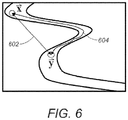
- the curvilinear distance 604 represents a constrained Euclidean distance between two points ( x , y ) along an optimal trajectory.
- the curvilinear distance 604 may be solved using: t ( x , y ) ⁇ t m ( y ) where t and t m represent the time (t) at ( x , y ) and the minimal travel time (t m ) at ( y ), respectively.
- the curvilinear distance 604 may be solved using the solution to the anisotropic Eikonal equation for a minimum travel time (t m ) along the optimal trajectory.
- the Euclidean distance 602 solves for the linear distance between two points ( x , y ) and is inaccurate for channelized features.
- CPP interpolation has only been implemented using a seismic data image as the underlying structural input.
- the integration method brings together other types and formats of geological and structural data (e.g. layering intervals, projection maps and hand drawings) as the input data for interpolation.
- FIG. 2 a flow diagram illustrates one embodiment of a method 200 for implementing step 106 in FIG. 1 .
- step 201 an image of a geological structure represented by the input data is digitized using any standard method well known in the art for representing an image by a discrete set of its points or samples such as, for example, rasterizing or image compression.
- the fundamental feature is to render a generic image format compatible with interpolation in step 108.
- IPoD intelligent point densification
- IPoD is an improvement of the atomic-meshing techniques described in U.S. Pat. No. 7,050,612 .
- IPoD is generally used to: 1) initialize the sample point location by filling the space spanned by the digitized image with a pseudo-regular lattice of points, where the nominal distance between the point and its nearest neighbors varies consistently with the density of structural features in the digitized image; and 2) optimize the sample point location by moving the points within the space spanned by the digitized image to minimize a total potential energy, defined to be a weighted sum of a point potential energy for each sample point and a potential energy for the digitized image.
- a total potential energy defined to be a weighted sum of a point potential energy for each sample point and a potential energy for the digitized image.
- step 203 a structure and diffusion tensor field is calculated for the digitized image from step 201 using methods well known in the art.
- the individually calculated tensors for the tensor field are linked with the corresponding sample point initialized and optimized in step 202 by IPoD. If the technique applied is the "nearest neighbor” search, then the tensor is linked to the nearest neighbor sample point. If the technique applied is the "natural neighbor” search, then the tensor is linked to the natural neighbor sample point. Both the nearest-neighbor search and natural-neighbor search techniques are well known in the art.
- the metric tensor field is the link between distance and time and represents the coherence, orientation and dimensionality of features in the image, which guide the interpolation in step 108 .
- the tensor field alters interpolation so that known sample values within spatially coherent image features are given more weight than values on opposite sides of such features or where the image is less coherent.
- Any underlying tensor field needs some underlying guiding representation in a computer such as, for example, a drawing, photograph, or other image. If derived from a seismic data image, the tensor field might be sampled with resolution of the seismic data image. Alternatively, the tensor field may be sampled more coarsely/cleverly using, for example, IPoD. This means that the tensor field will be sampled with the lower resolution only at the image locations determined by the optimized locations of the sample points from step 202 .
- step 204 the digitized image from step 201 is processed using structure-oriented smoothing along structures that are apparent in the image (i.e., calculated in the form of a structure and diffusion tensor field in step 203 ), which enhances structural features and preserves important discontinuities such as, for example, faults or channels.
- a broad spectrum of well-known filtering algorithms may be used such as, for example: i) coherency-enhancing anisotropic filters; ii) structure-oriented interpretation filters ( i.e. van Gogh filters); iii) recursive (anisotropic) Gaussian filters; and iv) novel implementations of bilateral filters.
- a fault displacement field (FDF) for the digitized image from step 201 is calculated in the manner described below.
- the FDF is merged with the results from step 203 and step 204 , which is returned to step 108 in FIG. 1 for interpolation.
- Traditional seismic interpretation methods focus on the detection of the fault line in the seismic data image through, for example, coherence methods. Calculating an FDF, however, corresponds to tracing the MCF through the fault line (in 2D) or through the fault surface (in 3D).
- step 205 may be applied to fault line/surface detection in the seismic data image as well as to any other format of digitized data pertaining to structural information (e.g.. layering intervals, projection maps and hand drawings).
- the FDF is therefore, calculated by searching for the apparent displacement vectors in the image and searching for the locations of peaks of local cross-correlations between adjacent, that is vertical, image traces.
- the FDF constrains fault vectors, which vary smoothly within a fault that is in the direction of the fault.
- a correlation smoothing window is applied, which is aligned with a lag vector.
- smoothing is applied for any lag vector in the direction of that vector by shearing where the correlation is done trace-by-tracc and is as fast as if it was done for the vertical faults. Shearing is a well known concept used in computer graphics algorithms.
- FIG. 4A the application of the Point Vector technology is illustrated for tracing the data-searched region 404a and the associated MCF 408a over a fault line 400a from region 404a to region 406a by displaying region 404a of the search and following the fault throw vector 402a to region 406a .
- this operation has to be performed on multiple-fault lines in a VOI for the entire MCF, it is extremely time-consuming and hard to efficiently implement in practice.
- FIG. 4B which is a 2D seismic data image representing amplitude, the calculated structure and diffusion tensor field, represented by the ellipsoids, docs not continue through the fault line.
- the areas represented by 402b, 404b and 406b reveal the areas where the directional information is lost. In other words, as the ellipsoids become less elongated, the information on directionality of the tensor field is lost on the fault line and discontinues tracing the MCF.
- tracing the MCF over fault lines is generically applicable to any underlying structural representation in a digital image
- Step 205 represents an improvement over the Point Vector technology, which does not require user pre-defined input for fault vectors and associated fault throws, which are required by the use of the Point Vector technology.
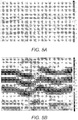
- a seismic data image illustrates a fault displacement field calculated according to step 205 on amplitude seismic data.
- FIG. 5B an enlarged image of the area circled in FIG. 5A illustrates the directional information for the fault displacement field.
- the directionality information i.e., vector arrows
- the vector arrows represent the calculated displacement vectors. It is evident from the absolute length of the vector arrows that the displacement is merely associated with the high-gradient-change features (e.g. fault throws), but not with the tilt variation of horizontal layering where the length of the vector arrows is reduced. This is the preferred behavior because the displacement vector field is envisioned as the structural property.
- Embodiments of the present invention are distinguished from existing technologies on the market by the integration of: i) Maximum Continuity Fields (MCF); ii) Intelligent Point Densification (IPoD); iii) fault displacement fields (FDF); and iv) CPP interpolation.
- MCF Maximum Continuity Fields
- IPoD Intelligent Point Densification
- FDF fault displacement fields
- CPP interpolation CPP interpolation
- Embodiments of the present invention may be implemented through a computer-executable program of instructions, such as program modules, generally referred to as software applications or application programs executed by a computer.
- the software may include, for example, routines, programs, objects, components, and data structures that perform particular tasks or implement particular abstract data types.
- the software forms an interface to allow a computer to react according to a source of input.
- DecisionSpace Earth Modeling DSEMTM
- Landmark Graphics which is a commercial software application marketed by Landmark Graphics, may be used as an interface application to implement the present invention.
- the software may also cooperate with other code segments to initiate a variety of tasks in response to data received in conjunction with the source of the received data.
- the software may be stored and/or carried on any variety of memory media such as CD-ROM, magnetic disk, bubble memory and semiconductor memory (e.g., various types of RAM or ROM). Furthermore, the software and its results may be transmitted over a variety of carrier media such as optical fiber, metallic wire and/or through any of a variety of networks such as the Internet.
- memory media such as CD-ROM, magnetic disk, bubble memory and semiconductor memory (e.g., various types of RAM or ROM).
- the software and its results may be transmitted over a variety of carrier media such as optical fiber, metallic wire and/or through any of a variety of networks such as the Internet.
- the invention may be practiced with a variety of computer-system configurations, including hand-held devices, multiprocessor systems, microprocessor-based or programmable-consumer electronics, minicomputers, mainframe computers, and the like. Any number of computer-systems and computer networks are acceptable for use with the present invention.
- the invention may be practiced in distributed-computing environments where tasks are performed by remote-processing devices that are linked through a communications network.
- program modules may be located in both local and remote computer-storage media including memory storage devices.
- the present invention may therefore, be implemented in connection with various hardware, software or a combination thereof, in a computer system or other processing system.
- the system includes a computing unit, sometimes referred to a computing system, which contains memory, application programs, a client interface, a video interface and a processing unit.
- the computing unit is only one example of a suitable computing environment and is not intended to suggest any limitation as to the scope of use or functionality of the invention.
- the memory primarily stores the application programs, which may also be described as program modules containing computer-executable instructions, executed by the computing unit for implementing the present invention described herein and illustrated in FIGS. 1-2 .
- the memory therefore, primarily includes a data input module, an abstraction module and a data interpolation module, which enable the methods illustrated and described in reference to FIGS. 1-2 .
- the data input module includes functionality supporting the input of seismic data, layering/intervals, map views and hand drawings. In other words, the data input module integrates with DSEMTM and the client/video interfaces to execute the functions described in reference to steps 102a, 104a, 104b and 104c in FIG. 1 .
- the data abstraction module integrates with DSEMTM to execute the functions described in reference to step 106 in FIG. 1 .
- the data abstraction module includes digitization, intelligent point densification, structure/diffusion tensors, structure-oriented smoothing and a fault displacement field components to execute the functions described in reference to steps 201-205 in FIG. 2 .
- the data interpolation module integrates with DSEMTM to execute the functions described in reference to step 108 in FIG. 1 .
- the computing unit typically includes a variety of computer readable media.
- computer readable media may comprise computer storage media.
- the computing system memory may include computer storage media in the form of volatile and/or nonvolatile memory such as a read only memory (ROM) and random access memory (RAM).
- ROM read only memory
- RAM random access memory
- a basic input/output system (BIOS) containing the basic routines that help to transfer information between elements within the computing unit, such as during start-up, is typically stored in ROM.
- the RAM typically contains data and/or program modules that are immediately accessible to and/or presently being operated on by the processing unit.
- the computing unit includes an operating system, application programs, other program modules, and program data.
- the components shown in the memory may also be included in other removable/nonremovable, volatile/nonvolatile computer storage media or they may be implemented in the computing unit through application program interface ("API"), which may reside on a separate computing unit connected through a computer system or network.
- API application program interface
- a hard disk drive may read from or write to nonremovable, nonvolatile magnetic media
- a magnetic disk drive may read from or write to a removable, non-volatile magnetic disk
- an optical disk drive may read from or write to a removable, nonvolatile optical disk such as a CD ROM or other optical media.
- removable/non-removable, volatile/non-volatile computer storage media may include, but are not limited to, magnetic tape cassettes, flash memory cards, digital versatile disks, digital video tape, solid state RAM, solid state ROM, and the like.
- the drives and their associated computer storage media discussed above provide storage of computer readable instructions, data structures, program modules and other data for the computing unit.
- a client may enter commands and information into the computing unit through the client interface, which may be input devices such as a keyboard and pointing device, commonly referred to as a mouse, trackball or touch pad.
- Input devices may include a microphone, joystick, satellite dish, scanner, or the like.
- a monitor or other type of display device may be connected to the system bus via an interface, such as a video interface.
- a graphical user interface may also be used with the video interface to receive instructions from the client interface and transmit instructions to the processing unit.
- computers may also include other peripheral output devices such as speakers and printer, which may be connected through an output peripheral interface.
Landscapes
- Physics & Mathematics (AREA)
- Life Sciences & Earth Sciences (AREA)
- Engineering & Computer Science (AREA)
- General Physics & Mathematics (AREA)
- General Life Sciences & Earth Sciences (AREA)
- Geophysics (AREA)
- Remote Sensing (AREA)
- Geology (AREA)
- Acoustics & Sound (AREA)
- Environmental & Geological Engineering (AREA)
- Software Systems (AREA)
- Theoretical Computer Science (AREA)
- Geometry (AREA)
- Computer Graphics (AREA)
- Image Processing (AREA)
- Geophysics And Detection Of Objects (AREA)
- Image Analysis (AREA)
- Apparatus For Radiation Diagnosis (AREA)
- Magnetic Resonance Imaging Apparatus (AREA)
Claims (8)
- Computerimplementiertes Verfahren zur Modellierung einer dreidimensionalen (3D) geologischen Struktur, wobei das Verfahren Folgendes umfasst:Auswählen (102, 104) von Eingabedaten, die Strukturinformationen der geologischen Struktur einschließlich eines Bildes der geologischen Struktur enthalten;Digitalisieren (201) des Bildes der geologischen Struktur, wobei das digitalisierte Bild mehrere Stichprobenpunkte umfasst;Verarbeiten (202) des digitalisierten Bildes unter Verwendung intelligenter Punktverdichtung, wobei die Verdichtung eine Position eines Stichprobenpunktes nur initialisiert und optimiert, wobei das Initialisieren durch das Füllen eines Raumes erfolgt, der durch das digitalisierte Bild mit einem pseudoregelmäßigen Verband von Punkten überspannt wird, in dem ein Sollabstand zwischen dem Stichprobenpunkt und dessen nächstem Nachbarn beständig mit der Dichte der Strukturmerkmale im digitalisierten Bild variiert, und das Optimieren durch das Bewegen der Punkte innerhalb des Raumes dazu erfolgt, eine gesamte potentielle Energie zu minimieren, die als eine gewichtete Summe einer punktbezogenen potentiellen Energie für jeden Stichprobenpunkt und einer potentiellen Energie für das digitalisierte Bild definiert ist;Berechnen (203) einer Struktur und eines Diffusionstensorfeldes für das digitalisierte Bild, wobei jeder Tensor (D) für das Tensorfeld mit einem jeweiligen Stichprobenpunkt an einer optimierten Stichprobenpunktposition für den jeweiligen Stichprobenpunkt verknüpft ist und jeder Tensorpunkt so ausgebildet ist, dass er Eigenvektoren nach einer lokalen Orientierung des digitalisierten Bildes aufweist;Verarbeiten (204) des digitalisierten Bildes zum Erstellen eines verbesserten Bildes, wobei das Verarbeiten strukturorientiertes Glätten entlang der im digitalisierten Bild offensichtlichen Strukturen verwendet, wobei die Strukturen in der Form der Struktur und des Diffusionstensorfeldes berechnet wurden;Berechnen (205) eines Fehler-Verschiebungsfeldes (fault displacement field - FDF) für das digitalisierte Bild unter Verwendung eines Computerprozessors, wobei das Fehler-Verschiebungsfeld mit der berechneten Struktur und dem berechneten Diffusionstensorfeld und dem verarbeiteten, strukturorientiert geglätteten, digitalisierten Bild zusammengelegt wird; undInterpolieren (108) des zusammengelegten berechneten Fehler-Verschiebungsfeldes, der berechneten Struktur und des berechneten Diffusionstensorfeldes und des verarbeiteten, strukturorientiert geglätteten, digitalisierten Bildes, um eine 3D geologisches Modell zu erzeugen.
- Verfahren nach Anspruch 1, wobei die Eingabedaten seismische Daten, Schichtungsintervalle, Kartenansichten und Handzeichnungen umfassen.
- Verfahren nach Anspruch 1 oder 2, wobei das Digitalisieren des Bildes eines von Rastern oder Komprimieren des Bildes umfasst.
- Verfahren nach einem der vorhergehenden Ansprüche, wobei die strukturorientierte Glättung mindestens eines der Folgendes umfasst: kohärenzverstärkende anisotrope Filter, strukturorientierte Interpretationsfilter, rekursive (anisotrope) Gauß-Filter und bilaterale Filter.
- Verfahren nach einem der vorhergehenden Ansprüche, wobei das Berechnen des Fehler-Verschiebungsfeldes für das digitalisierte Bild das Suchen nach offensichtlichen Verschiebungsvektoren im digitalisierten Bild und das Suchen nach den Positionen der Maxima der lokalen Kreuzkorrelationen zwischen angrenzenden vertikalen Spuren für das digitalisierte Bild umfasst.
- Verfahren nach einem der vorhergehenden Ansprüche, wobei der Schritt des Interpolierens die Interpolation durch natürliche Nachbarn umfasst.
- Verfahren nach einem der Ansprüche 1 bis 5, wobei der Schritt des Interpolierens die Interpolation durch bildgeführte vermischte Nachbarn umfasst.
- Auf einem Computer lesbares Medium, auf dem für den Computer ausführbare Anweisungen zum Modellieren einer dreidimensionalen (3D) geologischen Struktur gespeichert sind, wobei die Anweisungen, wenn sie von einem Computer ausgeführt werden, den Computer dazu veranlassen, das Verfahren nach einem der vorhergehenden Ansprüche durchzuführen.
Applications Claiming Priority (2)
| Application Number | Priority Date | Filing Date | Title |
|---|---|---|---|
| US12/710,253 US8274859B2 (en) | 2010-02-22 | 2010-02-22 | Systems and methods for modeling 3D geological structures |
| PCT/US2011/020569 WO2011102922A1 (en) | 2010-02-22 | 2011-01-07 | Systems and methods for modeling 3d geological structures |
Publications (3)
| Publication Number | Publication Date |
|---|---|
| EP2539740A1 EP2539740A1 (de) | 2013-01-02 |
| EP2539740A4 EP2539740A4 (de) | 2017-08-09 |
| EP2539740B1 true EP2539740B1 (de) | 2020-05-13 |
Family
ID=44476380
Family Applications (1)
| Application Number | Title | Priority Date | Filing Date |
|---|---|---|---|
| EP11745014.8A Not-in-force EP2539740B1 (de) | 2010-02-22 | 2011-01-07 | Systeme und verfahren zur modellierung dreidimensionaler geographischer strukturen |
Country Status (9)
| Country | Link |
|---|---|
| US (3) | US8274859B2 (de) |
| EP (1) | EP2539740B1 (de) |
| CN (1) | CN102893182B (de) |
| AU (1) | AU2011218479B2 (de) |
| BR (1) | BR112012020897A2 (de) |
| CA (1) | CA2787970C (de) |
| EA (2) | EA025919B1 (de) |
| MX (1) | MX2012009056A (de) |
| WO (1) | WO2011102922A1 (de) |
Families Citing this family (81)
| Publication number | Priority date | Publication date | Assignee | Title |
|---|---|---|---|---|
| CN102239507B (zh) * | 2008-12-03 | 2016-02-24 | 雪佛龙美国公司 | 用于离散裂隙建模的网格生成系统和方法 |
| GB2477901A (en) * | 2008-12-03 | 2011-08-17 | Chevron Usa Inc | System and method for predicting fluid flow characteristics within fractured subsurface reservoirs |
| US9536022B1 (en) | 2009-06-01 | 2017-01-03 | Paradigm Sciences Ltd. | Systems and methods for modeling faults in the subsurface |
| US9418182B2 (en) | 2009-06-01 | 2016-08-16 | Paradigm Sciences Ltd. | Systems and methods for building axes, co-axes and paleo-geographic coordinates related to a stratified geological volume |
| US8711140B1 (en) | 2009-06-01 | 2014-04-29 | Paradigm Sciences Ltd. | Systems and methods for building axes, co-axes and paleo-geographic coordinates related to a stratified geological volume |
| US8600708B1 (en) | 2009-06-01 | 2013-12-03 | Paradigm Sciences Ltd. | Systems and processes for building multiple equiprobable coherent geometrical models of the subsurface |
| US8743115B1 (en) | 2009-10-23 | 2014-06-03 | Paradigm Sciences Ltd. | Systems and methods for coordinated editing of seismic data in dual model |
| US8274859B2 (en) * | 2010-02-22 | 2012-09-25 | Landmark Graphics Corporation | Systems and methods for modeling 3D geological structures |
| US9582931B2 (en) * | 2010-02-26 | 2017-02-28 | Chevron U.S.A. Inc. | Surface smoothing within an earth model of a geological volume of interest |
| US20120022837A1 (en) * | 2010-05-18 | 2012-01-26 | Schlumberger Technology Corporation | Smoothing Of Stair-Stepped Geometry In Grids |
| MX2012012866A (es) * | 2010-06-18 | 2013-03-20 | Landmark Graphics Corp | Sistemas y metodos de computo de modelo de variograma de tres dimensiones por omision. |
| US20150009215A1 (en) * | 2012-02-17 | 2015-01-08 | Schlumberger Technology Corporation | Generating a 3d image for geological modeling |
| US10114134B2 (en) | 2012-03-02 | 2018-10-30 | Emerson Paradigm Holding Llc | Systems and methods for generating a geological model honoring horizons and faults |
| US9759826B2 (en) | 2012-04-03 | 2017-09-12 | Paradigm Sciences Ltd. | System and method for generating an implicit model of geological horizons |
| US9377546B2 (en) * | 2012-05-06 | 2016-06-28 | Schlumberger Technology Corporation | Automatic extraction and characterization of fault and fracture populations |
| GB2503507B (en) * | 2012-06-29 | 2015-04-15 | Foster Findlay Ass Ltd | Adaptive fault tracking |
| CN102830430B (zh) * | 2012-08-08 | 2016-03-02 | 电子科技大学 | 一种层位速度建模方法 |
| EP2901363A4 (de) * | 2012-09-28 | 2016-06-01 | Exxonmobil Upstream Res Co | Fehlerentfernung bei geologischen modellen |
| CN102914797B (zh) * | 2012-10-16 | 2015-04-08 | 中国石油天然气股份有限公司 | 一种获得地层各向异性系数的方法及装置 |
| US10481297B2 (en) | 2013-01-28 | 2019-11-19 | Westerngeco L.L.C. | Fluid migration pathway determination |
| GB2510872A (en) * | 2013-02-15 | 2014-08-20 | Total Sa | Method of modelling a subsurface volume |
| GB2510873A (en) | 2013-02-15 | 2014-08-20 | Total Sa | Method of modelling a subsurface volume |
| EP3418778B1 (de) | 2013-03-15 | 2020-07-15 | Emerson Paradigm Holding LLC | Systeme und verfahren zum aufbauen sedimentärer attribute |
| US9364995B2 (en) | 2013-03-15 | 2016-06-14 | Matterrise, Inc. | Three-dimensional printing and scanning system and method |
| US9341728B2 (en) * | 2013-07-29 | 2016-05-17 | Westerngeco L.L.C. | Methods of analyzing seismic data |
| WO2015023954A1 (en) * | 2013-08-16 | 2015-02-19 | Landmark Graphics Corporation | Identifying matching properties between a group of bodies representing a geological structure and a table of properties |
| US9869799B2 (en) * | 2013-09-09 | 2018-01-16 | Schlumberger Technology Corporation | Object-based well correlation |
| MX2016003639A (es) * | 2013-09-20 | 2016-10-28 | Westerngeco Seismic Holdings Ltd | Solucionador de la eikonal para cuasi ondas p en medios anisotropicos. |
| EP2869096B1 (de) | 2013-10-29 | 2019-12-04 | Emerson Paradigm Holding LLC | Systeme und verfahren zur multiskalaren vermaschung von geologischer zeitmodellierung |
| US9790770B2 (en) | 2013-10-30 | 2017-10-17 | The Texas A&M University System | Determining performance data for hydrocarbon reservoirs using diffusive time of flight as the spatial coordinate |
| US10241181B2 (en) | 2014-01-13 | 2019-03-26 | Siemens Healthcare Gmbh | Resolution enhancement of diffusion imaging biomarkers in magnetic resonance imaging |
| US10422923B2 (en) | 2014-03-28 | 2019-09-24 | Emerson Paradigm Holding Llc | Systems and methods for modeling fracture networks in reservoir volumes from microseismic events |
| CN103926616B (zh) * | 2014-04-11 | 2016-07-13 | 中国海洋石油总公司 | 一种基于叠前crp道集的多尺度各向异性扩散滤波方法 |
| US20150301208A1 (en) * | 2014-04-22 | 2015-10-22 | Westerngeco L.L.C. | Seismic data processing |
| US9613460B2 (en) * | 2014-05-09 | 2017-04-04 | Lenovo (Singapore) Pte. Ltd. | Augmenting a digital image |
| WO2015199727A1 (en) * | 2014-06-27 | 2015-12-30 | Hewlett-Packard Development Company, L.P. | Finding faults in geological data |
| US10816688B2 (en) | 2014-08-15 | 2020-10-27 | Equinor Energy As | Method and apparatus for measuring seismic data |
| CN104700368B (zh) * | 2015-03-06 | 2018-08-17 | 南京大树智能科技股份有限公司 | 基于核函数的数字图像相关方法的位移场自适应平滑方法 |
| BR112017014331A2 (pt) * | 2015-03-30 | 2018-03-06 | Halliburton Energy Services Inc | método, aparelho e sistema |
| US9690002B2 (en) | 2015-06-18 | 2017-06-27 | Paradigm Sciences Ltd. | Device, system and method for geological-time refinement |
| KR101625660B1 (ko) * | 2015-11-20 | 2016-05-31 | 한국지질자원연구원 | 지구통계기법에서의 관측자료를 이용한 2차자료 생성 방법 |
| CN105654551B (zh) * | 2015-12-29 | 2019-07-09 | 中国石油天然气集团公司 | 一种构建地质局部断层三维模型的方法及装置 |
| WO2017160273A1 (en) * | 2016-03-14 | 2017-09-21 | Schlumberger Technology Corporation | Dip estimation via a modified structure tensor |
| CN105869131B (zh) * | 2016-04-22 | 2018-07-17 | 东南大学 | 一种对缺失数据修补的位移场重构方法 |
| US10685482B2 (en) * | 2016-05-13 | 2020-06-16 | Chevron U.S.A. Inc. | System and method for 3D restoration of complex subsurface models |
| US10628552B2 (en) | 2016-06-07 | 2020-04-21 | Landmark Graphic Corporation | Systems and methods for unfaulting point clouds |
| CN106324668B (zh) * | 2016-08-16 | 2019-08-02 | 广东石油化工学院 | 一种基于双变地质建模技术的薄储层地震正演模拟方法 |
| FR3055723A1 (fr) * | 2016-09-02 | 2018-03-09 | Landmark Graphics Corporation | Modelisation basee sur un point-vecteur des proprietes de reservoir de petrole pour un modele de simulation de reservoir sans grille |
| US10466388B2 (en) | 2016-09-07 | 2019-11-05 | Emerson Paradigm Holding Llc | System and method for editing geological models by switching between volume-based models and surface-based structural models augmented with stratigraphic fiber bundles |
| CN106501856B (zh) * | 2016-10-20 | 2018-07-27 | 东北石油大学 | 亚地震断层定量预测方法 |
| WO2018093599A1 (en) * | 2016-11-17 | 2018-05-24 | Landmark Graphics Corporation | Multi-z horizon interpretation and editing within seismic data |
| US11263801B2 (en) | 2017-03-31 | 2022-03-01 | Schlumberger Technology Corporation | Smooth surface wrapping of features in an imaged volume |
| CN107479693A (zh) * | 2017-07-07 | 2017-12-15 | 大圣科技股份有限公司 | 基于rgb信息的实时手部识别方法、存储介质、电子设备 |
| CN109242781B (zh) * | 2017-07-10 | 2020-12-01 | 中国石油化工股份有限公司 | 保地质边界的地震图像去噪方法及计算机可读存储介质 |
| CN109242770B (zh) * | 2017-07-10 | 2021-12-24 | 中国石油化工股份有限公司 | 图像导引的地震速度插值方法及计算机可读存储介质 |
| US10996358B2 (en) * | 2017-08-18 | 2021-05-04 | Saudi Arabian Oil Company | Image-guided velocity interpolation using a mask cube |
| WO2019050545A1 (en) * | 2017-09-11 | 2019-03-14 | Landmark Graphics Corporation | TOPOLOGICALLY CORRECT HORIZONS OF COMPLEX FAILURE NETWORK |
| CN108961409B (zh) * | 2018-06-15 | 2020-11-13 | 北京大学 | 一种基于油藏三维地质体构建3d打印物理模型的方法 |
| CN110954957B (zh) * | 2018-09-26 | 2021-12-24 | 中国石油化工股份有限公司 | 三维地震数据的空间融合方法及计算机可读存储介质 |
| GB2591898A (en) * | 2018-12-20 | 2021-08-11 | Landmark Graphics Corp | Seamless scaling geomodeling |
| CN109712238B (zh) * | 2018-12-25 | 2023-06-06 | 长江大学 | 平滑处理地质模型的方法及设备 |
| US10520644B1 (en) | 2019-01-10 | 2019-12-31 | Emerson Paradigm Holding Llc | Imaging a subsurface geological model at a past intermediate restoration time |
| US11156744B2 (en) | 2019-01-10 | 2021-10-26 | Emerson Paradigm Holding Llc | Imaging a subsurface geological model at a past intermediate restoration time |
| US10983233B2 (en) | 2019-03-12 | 2021-04-20 | Saudi Arabian Oil Company | Method for dynamic calibration and simultaneous closed-loop inversion of simulation models of fractured reservoirs |
| CN110544304B (zh) * | 2019-07-18 | 2023-03-14 | 长春市万易科技有限公司 | 基于时空推理的场地污染数字化与图形化展示系统及方法 |
| CN110599595B (zh) * | 2019-08-09 | 2023-12-01 | 中冶北方(大连)工程技术有限公司 | 一种地质构造的三维表征方法 |
| US11499397B2 (en) | 2019-10-31 | 2022-11-15 | Saudi Arabian Oil Company | Dynamic calibration of reservoir simulation models using flux conditioning |
| US11501038B2 (en) | 2019-10-31 | 2022-11-15 | Saudi Arabian Oil Company | Dynamic calibration of reservoir simulation models using pattern recognition |
| EP3819679B1 (de) * | 2019-11-08 | 2024-08-07 | TotalEnergies OneTech | Verfahren zur bestimmung eines echten geologischen formations des untergrundes |
| US12596203B2 (en) | 2020-01-22 | 2026-04-07 | Totalenergies Onetech | Layering for geomodeling |
| CN111624652B (zh) * | 2020-04-17 | 2023-04-25 | 中国石油天然气股份有限公司 | 确定地层中地质参数的方法 |
| CN111929725B (zh) * | 2020-07-29 | 2021-07-02 | 中国石油大学(北京) | 一种地震数据插值方法、装置及设备 |
| CN112084280B (zh) * | 2020-09-04 | 2023-07-21 | 广州南方智能技术有限公司 | 一种多尺度地形的裁剪及拼接方法 |
| US12189072B2 (en) | 2020-10-05 | 2025-01-07 | Saudi Arabian Oil Company | System and method to identify high-impact discrete fracture model realizations for accelerated calibration of reservoir simulation models |
| US12361610B2 (en) | 2020-12-17 | 2025-07-15 | Schlumberger Technology Corporation | Predictive geological drawing system and method |
| CN112862967B (zh) * | 2021-03-11 | 2023-07-18 | 北京市水利规划设计研究院 | 用于建立三维地质模型的方法和装置 |
| EP4441533A4 (de) * | 2021-11-30 | 2025-11-26 | Services Petroliers Schlumberger | Eigenschaftsmodellierung mit attentiven neuronalen prozessen |
| US20230252202A1 (en) * | 2022-02-09 | 2023-08-10 | Saudi Arabian Oil Company | Quantification of expressive experimental semi-variogram ranges uncertainties |
| US20240078640A1 (en) * | 2022-09-01 | 2024-03-07 | Apple Inc. | Perspective Correction with Gravitational Smoothing |
| CN118482685B (zh) * | 2024-05-11 | 2024-12-27 | 广东工业大学 | 融合时间序列与时空形变的地下开采沉降监测方法及系统 |
| CN119828221B (zh) * | 2025-01-10 | 2025-10-28 | 中国石油大学(北京) | 一种目标层位的插值处理方法和装置 |
Family Cites Families (14)
| Publication number | Priority date | Publication date | Assignee | Title |
|---|---|---|---|---|
| US6631202B2 (en) * | 2000-12-08 | 2003-10-07 | Landmark Graphics Corporation | Method for aligning a lattice of points in response to features in a digital image |
| US6791900B2 (en) * | 2002-06-13 | 2004-09-14 | Exxonmobil Upstream Research Company | Method of calculating a throw volume for quantitative fault analysis |
| US6987511B2 (en) * | 2002-10-17 | 2006-01-17 | International Business Machines Corporation | Linear anisotrophic mesh filtering |
| CN1898675A (zh) * | 2004-01-30 | 2007-01-17 | 埃克森美孚上游研究公司 | 储层模型建立方法 |
| US7379626B2 (en) * | 2004-08-20 | 2008-05-27 | Silicon Optix Inc. | Edge adaptive image expansion and enhancement system and method |
| US7630530B2 (en) * | 2005-01-14 | 2009-12-08 | Siemens Medical Solutions Usa, Inc. | System and method for fast tensor field segmentation |
| US7355403B2 (en) * | 2005-01-27 | 2008-04-08 | Siemens Medical Solutions Usa, Inc. | Noise reduction in diffusion tensor imaging data using bayesian methods |
| FR2884335B1 (fr) * | 2005-04-07 | 2007-11-30 | Inst Nat Rech Inf Automat | Dispositif perfectionne de traitement d'images brutes ou d'images de tenseurs |
| US7660481B2 (en) * | 2005-11-17 | 2010-02-09 | Vital Images, Inc. | Image enhancement using anisotropic noise filtering |
| WO2007085048A1 (en) * | 2006-01-24 | 2007-08-02 | Desmond Fitzgerald & Associates Pty Ltd | An improved method of interpolation between a plurality of observed tensors |
| US8369579B2 (en) * | 2006-12-21 | 2013-02-05 | Massachusetts Institute Of Technology | Methods and apparatus for 3D surface imaging using active wave-front sampling |
| MY164574A (en) * | 2008-05-22 | 2018-01-15 | Exxonmobil Upstream Res Co | Seismic horizon skeletonization |
| MX2010013221A (es) | 2008-06-09 | 2011-04-05 | Landmark Graphics Corp | Distribucion de propiedades en un modelo volumetrico tridimensional utilizando un campo de continuidad maxima. |
| US8274859B2 (en) * | 2010-02-22 | 2012-09-25 | Landmark Graphics Corporation | Systems and methods for modeling 3D geological structures |
-
2010
- 2010-02-22 US US12/710,253 patent/US8274859B2/en active Active
-
2011
- 2011-01-07 AU AU2011218479A patent/AU2011218479B2/en not_active Ceased
- 2011-01-07 EA EA201201175A patent/EA025919B1/ru not_active IP Right Cessation
- 2011-01-07 BR BR112012020897A patent/BR112012020897A2/pt not_active IP Right Cessation
- 2011-01-07 CA CA2787970A patent/CA2787970C/en not_active Expired - Fee Related
- 2011-01-07 MX MX2012009056A patent/MX2012009056A/es active IP Right Grant
- 2011-01-07 EP EP11745014.8A patent/EP2539740B1/de not_active Not-in-force
- 2011-01-07 CN CN201180010575.6A patent/CN102893182B/zh not_active Expired - Fee Related
- 2011-01-07 WO PCT/US2011/020569 patent/WO2011102922A1/en not_active Ceased
- 2011-01-07 EA EA201691707A patent/EA034189B1/ru not_active IP Right Cessation
-
2012
- 2012-08-27 US US13/595,773 patent/US8619499B2/en active Active
-
2013
- 2013-11-22 US US14/088,118 patent/US9646414B2/en active Active
Non-Patent Citations (1)
| Title |
|---|
| None * |
Also Published As
| Publication number | Publication date |
|---|---|
| EA034189B1 (ru) | 2020-01-15 |
| US20130027398A1 (en) | 2013-01-31 |
| EA025919B1 (ru) | 2017-02-28 |
| US20140078140A1 (en) | 2014-03-20 |
| WO2011102922A1 (en) | 2011-08-25 |
| AU2011218479B2 (en) | 2014-06-26 |
| EA201201175A1 (ru) | 2013-02-28 |
| EP2539740A1 (de) | 2013-01-02 |
| US20110205844A1 (en) | 2011-08-25 |
| EP2539740A4 (de) | 2017-08-09 |
| CN102893182B (zh) | 2016-05-04 |
| EA201691707A1 (ru) | 2017-01-30 |
| CN102893182A (zh) | 2013-01-23 |
| CA2787970A1 (en) | 2011-08-25 |
| BR112012020897A2 (pt) | 2018-04-03 |
| AU2011218479A1 (en) | 2012-08-09 |
| US8619499B2 (en) | 2013-12-31 |
| MX2012009056A (es) | 2012-12-17 |
| US9646414B2 (en) | 2017-05-09 |
| CA2787970C (en) | 2016-10-18 |
| US8274859B2 (en) | 2012-09-25 |
Similar Documents
| Publication | Publication Date | Title |
|---|---|---|
| EP2539740B1 (de) | Systeme und verfahren zur modellierung dreidimensionaler geographischer strukturen | |
| EP2888606B1 (de) | Verfahren und system zur tiefenumwandlung seismischer 3d-daten mit künstlichen neuronalen netzwerken | |
| US10385658B2 (en) | In-situ wellbore, core and cuttings information system | |
| WO2017082856A1 (en) | Modelling complex geological sequences using geologic rules and paleographic maps | |
| EP2756447B1 (de) | Systeme und verfahren für unterstützte eigenschaftsmodellierung | |
| AU2014386269B2 (en) | Modeling geologic surfaces using unilateral non-node constraints from neighboring surfaces in the stratigraphic sequence | |
| US20240255666A1 (en) | Linear-radon-marchenko equation based internal multiple elimination | |
| US20130158962A1 (en) | Systems and Methods for Computing a Default 3D Variogram Model | |
| US20250076527A1 (en) | Method to correct erroneous local traveltime operators | |
| WO2025156152A1 (en) | Optimized seismic acquisition geometry design based on spatial compressive sensing | |
| US12554030B2 (en) | Method and system for true absolute amplitude seismic imaging | |
| US20240280717A1 (en) | Efficient nonlinear beamforming via on-the-fly model-space reconstruction | |
| Maučec et al. | Next generation geological modeling for hydrocarbon reservoir characterization | |
| WO2025147591A1 (en) | Method for validating paleogeographic models using seismic data | |
| US20190004197A1 (en) | Updating models of complex geological sequences field of the disclosure |
Legal Events
| Date | Code | Title | Description |
|---|---|---|---|
| PUAI | Public reference made under article 153(3) epc to a published international application that has entered the european phase |
Free format text: ORIGINAL CODE: 0009012 |
|
| 17P | Request for examination filed |
Effective date: 20120905 |
|
| AK | Designated contracting states |
Kind code of ref document: A1 Designated state(s): AL AT BE BG CH CY CZ DE DK EE ES FI FR GB GR HR HU IE IS IT LI LT LU LV MC MK MT NL NO PL PT RO RS SE SI SK SM TR |
|
| DAX | Request for extension of the european patent (deleted) | ||
| RA4 | Supplementary search report drawn up and despatched (corrected) |
Effective date: 20170706 |
|
| RIC1 | Information provided on ipc code assigned before grant |
Ipc: G01V 1/28 20060101AFI20170630BHEP Ipc: G01V 1/00 20060101ALI20170630BHEP Ipc: G06T 17/00 20060101ALI20170630BHEP Ipc: G01V 99/00 20090101ALI20170630BHEP |
|
| STAA | Information on the status of an ep patent application or granted ep patent |
Free format text: STATUS: EXAMINATION IS IN PROGRESS |
|
| 17Q | First examination report despatched |
Effective date: 20190411 |
|
| GRAP | Despatch of communication of intention to grant a patent |
Free format text: ORIGINAL CODE: EPIDOSNIGR1 |
|
| STAA | Information on the status of an ep patent application or granted ep patent |
Free format text: STATUS: GRANT OF PATENT IS INTENDED |
|
| INTG | Intention to grant announced |
Effective date: 20191213 |
|
| RIN1 | Information on inventor provided before grant (corrected) |
Inventor name: MAUCEC, MARKO Inventor name: YARUS, JEFFREY M. Inventor name: LIANG, LU MING |
|
| GRAS | Grant fee paid |
Free format text: ORIGINAL CODE: EPIDOSNIGR3 |
|
| GRAA | (expected) grant |
Free format text: ORIGINAL CODE: 0009210 |
|
| STAA | Information on the status of an ep patent application or granted ep patent |
Free format text: STATUS: THE PATENT HAS BEEN GRANTED |
|
| RAP1 | Party data changed (applicant data changed or rights of an application transferred) |
Owner name: LANDMARK GRAPHICS CORPORATION |
|
| AK | Designated contracting states |
Kind code of ref document: B1 Designated state(s): AL AT BE BG CH CY CZ DE DK EE ES FI FR GB GR HR HU IE IS IT LI LT LU LV MC MK MT NL NO PL PT RO RS SE SI SK SM TR |
|
| REG | Reference to a national code |
Ref country code: GB Ref legal event code: FG4D |
|
| REG | Reference to a national code |
Ref country code: CH Ref legal event code: EP |
|
| REG | Reference to a national code |
Ref country code: DE Ref legal event code: R096 Ref document number: 602011066840 Country of ref document: DE |
|
| REG | Reference to a national code |
Ref country code: AT Ref legal event code: REF Ref document number: 1271017 Country of ref document: AT Kind code of ref document: T Effective date: 20200615 |
|
| REG | Reference to a national code |
Ref country code: LT Ref legal event code: MG4D |
|
| REG | Reference to a national code |
Ref country code: NL Ref legal event code: MP Effective date: 20200513 |
|
| PG25 | Lapsed in a contracting state [announced via postgrant information from national office to epo] |
Ref country code: LT Free format text: LAPSE BECAUSE OF FAILURE TO SUBMIT A TRANSLATION OF THE DESCRIPTION OR TO PAY THE FEE WITHIN THE PRESCRIBED TIME-LIMIT Effective date: 20200513 Ref country code: FI Free format text: LAPSE BECAUSE OF FAILURE TO SUBMIT A TRANSLATION OF THE DESCRIPTION OR TO PAY THE FEE WITHIN THE PRESCRIBED TIME-LIMIT Effective date: 20200513 Ref country code: SE Free format text: LAPSE BECAUSE OF FAILURE TO SUBMIT A TRANSLATION OF THE DESCRIPTION OR TO PAY THE FEE WITHIN THE PRESCRIBED TIME-LIMIT Effective date: 20200513 Ref country code: PT Free format text: LAPSE BECAUSE OF FAILURE TO SUBMIT A TRANSLATION OF THE DESCRIPTION OR TO PAY THE FEE WITHIN THE PRESCRIBED TIME-LIMIT Effective date: 20200914 Ref country code: IS Free format text: LAPSE BECAUSE OF FAILURE TO SUBMIT A TRANSLATION OF THE DESCRIPTION OR TO PAY THE FEE WITHIN THE PRESCRIBED TIME-LIMIT Effective date: 20200913 Ref country code: GR Free format text: LAPSE BECAUSE OF FAILURE TO SUBMIT A TRANSLATION OF THE DESCRIPTION OR TO PAY THE FEE WITHIN THE PRESCRIBED TIME-LIMIT Effective date: 20200814 Ref country code: NO Free format text: LAPSE BECAUSE OF FAILURE TO SUBMIT A TRANSLATION OF THE DESCRIPTION OR TO PAY THE FEE WITHIN THE PRESCRIBED TIME-LIMIT Effective date: 20200813 |
|
| PG25 | Lapsed in a contracting state [announced via postgrant information from national office to epo] |
Ref country code: RS Free format text: LAPSE BECAUSE OF FAILURE TO SUBMIT A TRANSLATION OF THE DESCRIPTION OR TO PAY THE FEE WITHIN THE PRESCRIBED TIME-LIMIT Effective date: 20200513 Ref country code: BG Free format text: LAPSE BECAUSE OF FAILURE TO SUBMIT A TRANSLATION OF THE DESCRIPTION OR TO PAY THE FEE WITHIN THE PRESCRIBED TIME-LIMIT Effective date: 20200813 Ref country code: LV Free format text: LAPSE BECAUSE OF FAILURE TO SUBMIT A TRANSLATION OF THE DESCRIPTION OR TO PAY THE FEE WITHIN THE PRESCRIBED TIME-LIMIT Effective date: 20200513 Ref country code: HR Free format text: LAPSE BECAUSE OF FAILURE TO SUBMIT A TRANSLATION OF THE DESCRIPTION OR TO PAY THE FEE WITHIN THE PRESCRIBED TIME-LIMIT Effective date: 20200513 |
|
| REG | Reference to a national code |
Ref country code: AT Ref legal event code: MK05 Ref document number: 1271017 Country of ref document: AT Kind code of ref document: T Effective date: 20200513 |
|
| PG25 | Lapsed in a contracting state [announced via postgrant information from national office to epo] |
Ref country code: AL Free format text: LAPSE BECAUSE OF FAILURE TO SUBMIT A TRANSLATION OF THE DESCRIPTION OR TO PAY THE FEE WITHIN THE PRESCRIBED TIME-LIMIT Effective date: 20200513 Ref country code: NL Free format text: LAPSE BECAUSE OF FAILURE TO SUBMIT A TRANSLATION OF THE DESCRIPTION OR TO PAY THE FEE WITHIN THE PRESCRIBED TIME-LIMIT Effective date: 20200513 |
|
| PG25 | Lapsed in a contracting state [announced via postgrant information from national office to epo] |
Ref country code: ES Free format text: LAPSE BECAUSE OF FAILURE TO SUBMIT A TRANSLATION OF THE DESCRIPTION OR TO PAY THE FEE WITHIN THE PRESCRIBED TIME-LIMIT Effective date: 20200513 Ref country code: CZ Free format text: LAPSE BECAUSE OF FAILURE TO SUBMIT A TRANSLATION OF THE DESCRIPTION OR TO PAY THE FEE WITHIN THE PRESCRIBED TIME-LIMIT Effective date: 20200513 Ref country code: RO Free format text: LAPSE BECAUSE OF FAILURE TO SUBMIT A TRANSLATION OF THE DESCRIPTION OR TO PAY THE FEE WITHIN THE PRESCRIBED TIME-LIMIT Effective date: 20200513 Ref country code: EE Free format text: LAPSE BECAUSE OF FAILURE TO SUBMIT A TRANSLATION OF THE DESCRIPTION OR TO PAY THE FEE WITHIN THE PRESCRIBED TIME-LIMIT Effective date: 20200513 Ref country code: SM Free format text: LAPSE BECAUSE OF FAILURE TO SUBMIT A TRANSLATION OF THE DESCRIPTION OR TO PAY THE FEE WITHIN THE PRESCRIBED TIME-LIMIT Effective date: 20200513 Ref country code: IT Free format text: LAPSE BECAUSE OF FAILURE TO SUBMIT A TRANSLATION OF THE DESCRIPTION OR TO PAY THE FEE WITHIN THE PRESCRIBED TIME-LIMIT Effective date: 20200513 Ref country code: AT Free format text: LAPSE BECAUSE OF FAILURE TO SUBMIT A TRANSLATION OF THE DESCRIPTION OR TO PAY THE FEE WITHIN THE PRESCRIBED TIME-LIMIT Effective date: 20200513 Ref country code: DK Free format text: LAPSE BECAUSE OF FAILURE TO SUBMIT A TRANSLATION OF THE DESCRIPTION OR TO PAY THE FEE WITHIN THE PRESCRIBED TIME-LIMIT Effective date: 20200513 |
|
| REG | Reference to a national code |
Ref country code: DE Ref legal event code: R097 Ref document number: 602011066840 Country of ref document: DE |
|
| PG25 | Lapsed in a contracting state [announced via postgrant information from national office to epo] |
Ref country code: PL Free format text: LAPSE BECAUSE OF FAILURE TO SUBMIT A TRANSLATION OF THE DESCRIPTION OR TO PAY THE FEE WITHIN THE PRESCRIBED TIME-LIMIT Effective date: 20200513 Ref country code: SK Free format text: LAPSE BECAUSE OF FAILURE TO SUBMIT A TRANSLATION OF THE DESCRIPTION OR TO PAY THE FEE WITHIN THE PRESCRIBED TIME-LIMIT Effective date: 20200513 |
|
| PLBE | No opposition filed within time limit |
Free format text: ORIGINAL CODE: 0009261 |
|
| STAA | Information on the status of an ep patent application or granted ep patent |
Free format text: STATUS: NO OPPOSITION FILED WITHIN TIME LIMIT |
|
| 26N | No opposition filed |
Effective date: 20210216 |
|
| PG25 | Lapsed in a contracting state [announced via postgrant information from national office to epo] |
Ref country code: SI Free format text: LAPSE BECAUSE OF FAILURE TO SUBMIT A TRANSLATION OF THE DESCRIPTION OR TO PAY THE FEE WITHIN THE PRESCRIBED TIME-LIMIT Effective date: 20200513 |
|
| REG | Reference to a national code |
Ref country code: DE Ref legal event code: R119 Ref document number: 602011066840 Country of ref document: DE |
|
| PG25 | Lapsed in a contracting state [announced via postgrant information from national office to epo] |
Ref country code: MC Free format text: LAPSE BECAUSE OF FAILURE TO SUBMIT A TRANSLATION OF THE DESCRIPTION OR TO PAY THE FEE WITHIN THE PRESCRIBED TIME-LIMIT Effective date: 20200513 |
|
| REG | Reference to a national code |
Ref country code: CH Ref legal event code: PL |
|
| GBPC | Gb: european patent ceased through non-payment of renewal fee |
Effective date: 20210107 |
|
| PG25 | Lapsed in a contracting state [announced via postgrant information from national office to epo] |
Ref country code: LU Free format text: LAPSE BECAUSE OF NON-PAYMENT OF DUE FEES Effective date: 20210107 |
|
| REG | Reference to a national code |
Ref country code: BE Ref legal event code: MM Effective date: 20210131 |
|
| PG25 | Lapsed in a contracting state [announced via postgrant information from national office to epo] |
Ref country code: FR Free format text: LAPSE BECAUSE OF NON-PAYMENT OF DUE FEES Effective date: 20210131 |
|
| PG25 | Lapsed in a contracting state [announced via postgrant information from national office to epo] |
Ref country code: LI Free format text: LAPSE BECAUSE OF NON-PAYMENT OF DUE FEES Effective date: 20210131 Ref country code: GB Free format text: LAPSE BECAUSE OF NON-PAYMENT OF DUE FEES Effective date: 20210107 Ref country code: CH Free format text: LAPSE BECAUSE OF NON-PAYMENT OF DUE FEES Effective date: 20210131 Ref country code: DE Free format text: LAPSE BECAUSE OF NON-PAYMENT OF DUE FEES Effective date: 20210803 |
|
| PG25 | Lapsed in a contracting state [announced via postgrant information from national office to epo] |
Ref country code: IE Free format text: LAPSE BECAUSE OF NON-PAYMENT OF DUE FEES Effective date: 20210107 |
|
| PG25 | Lapsed in a contracting state [announced via postgrant information from national office to epo] |
Ref country code: BE Free format text: LAPSE BECAUSE OF NON-PAYMENT OF DUE FEES Effective date: 20210131 |
|
| PG25 | Lapsed in a contracting state [announced via postgrant information from national office to epo] |
Ref country code: HU Free format text: LAPSE BECAUSE OF FAILURE TO SUBMIT A TRANSLATION OF THE DESCRIPTION OR TO PAY THE FEE WITHIN THE PRESCRIBED TIME-LIMIT; INVALID AB INITIO Effective date: 20110107 Ref country code: CY Free format text: LAPSE BECAUSE OF FAILURE TO SUBMIT A TRANSLATION OF THE DESCRIPTION OR TO PAY THE FEE WITHIN THE PRESCRIBED TIME-LIMIT Effective date: 20200513 |
|
| PG25 | Lapsed in a contracting state [announced via postgrant information from national office to epo] |
Ref country code: MK Free format text: LAPSE BECAUSE OF FAILURE TO SUBMIT A TRANSLATION OF THE DESCRIPTION OR TO PAY THE FEE WITHIN THE PRESCRIBED TIME-LIMIT Effective date: 20200513 |
|
| PG25 | Lapsed in a contracting state [announced via postgrant information from national office to epo] |
Ref country code: TR Free format text: LAPSE BECAUSE OF FAILURE TO SUBMIT A TRANSLATION OF THE DESCRIPTION OR TO PAY THE FEE WITHIN THE PRESCRIBED TIME-LIMIT Effective date: 20200513 |
|
| PG25 | Lapsed in a contracting state [announced via postgrant information from national office to epo] |
Ref country code: MT Free format text: LAPSE BECAUSE OF FAILURE TO SUBMIT A TRANSLATION OF THE DESCRIPTION OR TO PAY THE FEE WITHIN THE PRESCRIBED TIME-LIMIT Effective date: 20200513 |