EP2538529A2 - Elektrische Maschine mit gegenläufigen Rotoren - Google Patents
Elektrische Maschine mit gegenläufigen Rotoren Download PDFInfo
- Publication number
- EP2538529A2 EP2538529A2 EP12172351A EP12172351A EP2538529A2 EP 2538529 A2 EP2538529 A2 EP 2538529A2 EP 12172351 A EP12172351 A EP 12172351A EP 12172351 A EP12172351 A EP 12172351A EP 2538529 A2 EP2538529 A2 EP 2538529A2
- Authority
- EP
- European Patent Office
- Prior art keywords
- rotor
- rotors
- electrical machine
- poles
- stator member
- Prior art date
- Legal status (The legal status is an assumption and is not a legal conclusion. Google has not performed a legal analysis and makes no representation as to the accuracy of the status listed.)
- Granted
Links
Images


Classifications
-
- H—ELECTRICITY
- H02—GENERATION; CONVERSION OR DISTRIBUTION OF ELECTRIC POWER
- H02K—DYNAMO-ELECTRIC MACHINES
- H02K51/00—Dynamo-electric gears, i.e. dynamo-electric means for transmitting mechanical power from a driving shaft to a driven shaft and comprising structurally interrelated motor and generator parts
-
- H—ELECTRICITY
- H02—GENERATION; CONVERSION OR DISTRIBUTION OF ELECTRIC POWER
- H02K—DYNAMO-ELECTRIC MACHINES
- H02K16/00—Machines with more than one rotor or stator
-
- H—ELECTRICITY
- H02—GENERATION; CONVERSION OR DISTRIBUTION OF ELECTRIC POWER
- H02K—DYNAMO-ELECTRIC MACHINES
- H02K7/00—Arrangements for handling mechanical energy structurally associated with dynamo-electric machines, e.g. structural association with mechanical driving motors or auxiliary dynamo-electric machines
- H02K7/18—Structural association of electric generators with mechanical driving motors, e.g. with turbines
- H02K7/1807—Rotary generators
- H02K7/1823—Rotary generators structurally associated with turbines or similar engines
- H02K7/183—Rotary generators structurally associated with turbines or similar engines wherein the turbine is a wind turbine
- H02K7/1838—Generators mounted in a nacelle or similar structure of a horizontal axis wind turbine
-
- H—ELECTRICITY
- H02—GENERATION; CONVERSION OR DISTRIBUTION OF ELECTRIC POWER
- H02K—DYNAMO-ELECTRIC MACHINES
- H02K19/00—Synchronous motors or generators
- H02K19/02—Synchronous motors
- H02K19/04—Synchronous motors for single-phase current
- H02K19/06—Motors having windings on the stator and a variable-reluctance soft-iron rotor without windings, e.g. inductor motors
-
- H—ELECTRICITY
- H02—GENERATION; CONVERSION OR DISTRIBUTION OF ELECTRIC POWER
- H02K—DYNAMO-ELECTRIC MACHINES
- H02K19/00—Synchronous motors or generators
- H02K19/02—Synchronous motors
- H02K19/10—Synchronous motors for multi-phase current
- H02K19/103—Motors having windings on the stator and a variable reluctance soft-iron rotor without windings
-
- H—ELECTRICITY
- H02—GENERATION; CONVERSION OR DISTRIBUTION OF ELECTRIC POWER
- H02K—DYNAMO-ELECTRIC MACHINES
- H02K19/00—Synchronous motors or generators
- H02K19/16—Synchronous generators
- H02K19/22—Synchronous generators having windings each turn of which co-operates alternately with poles of opposite polarity, e.g. heteropolar generators
- H02K19/24—Synchronous generators having windings each turn of which co-operates alternately with poles of opposite polarity, e.g. heteropolar generators with variable-reluctance soft-iron rotors without winding
-
- H—ELECTRICITY
- H02—GENERATION; CONVERSION OR DISTRIBUTION OF ELECTRIC POWER
- H02K—DYNAMO-ELECTRIC MACHINES
- H02K21/00—Synchronous motors having permanent magnets; Synchronous generators having permanent magnets
- H02K21/38—Synchronous motors having permanent magnets; Synchronous generators having permanent magnets with rotating flux distributors, and armatures and magnets both stationary
- H02K21/40—Synchronous motors having permanent magnets; Synchronous generators having permanent magnets with rotating flux distributors, and armatures and magnets both stationary with flux distributors rotating around the magnets and within the armatures
-
- H—ELECTRICITY
- H02—GENERATION; CONVERSION OR DISTRIBUTION OF ELECTRIC POWER
- H02K—DYNAMO-ELECTRIC MACHINES
- H02K21/00—Synchronous motors having permanent magnets; Synchronous generators having permanent magnets
- H02K21/38—Synchronous motors having permanent magnets; Synchronous generators having permanent magnets with rotating flux distributors, and armatures and magnets both stationary
- H02K21/42—Synchronous motors having permanent magnets; Synchronous generators having permanent magnets with rotating flux distributors, and armatures and magnets both stationary with flux distributors rotating around the armatures and within the magnets
-
- H—ELECTRICITY
- H02—GENERATION; CONVERSION OR DISTRIBUTION OF ELECTRIC POWER
- H02K—DYNAMO-ELECTRIC MACHINES
- H02K7/00—Arrangements for handling mechanical energy structurally associated with dynamo-electric machines, e.g. structural association with mechanical driving motors or auxiliary dynamo-electric machines
- H02K7/10—Structural association with clutches, brakes, gears, pulleys or mechanical starters
- H02K7/11—Structural association with clutches, brakes, gears, pulleys or mechanical starters with dynamo-electric clutches
-
- H—ELECTRICITY
- H02—GENERATION; CONVERSION OR DISTRIBUTION OF ELECTRIC POWER
- H02K—DYNAMO-ELECTRIC MACHINES
- H02K7/00—Arrangements for handling mechanical energy structurally associated with dynamo-electric machines, e.g. structural association with mechanical driving motors or auxiliary dynamo-electric machines
- H02K7/10—Structural association with clutches, brakes, gears, pulleys or mechanical starters
- H02K7/116—Structural association with clutches, brakes, gears, pulleys or mechanical starters with gears
-
- H—ELECTRICITY
- H02—GENERATION; CONVERSION OR DISTRIBUTION OF ELECTRIC POWER
- H02K—DYNAMO-ELECTRIC MACHINES
- H02K7/00—Arrangements for handling mechanical energy structurally associated with dynamo-electric machines, e.g. structural association with mechanical driving motors or auxiliary dynamo-electric machines
- H02K7/18—Structural association of electric generators with mechanical driving motors, e.g. with turbines
- H02K7/1807—Rotary generators
- H02K7/1823—Rotary generators structurally associated with turbines or similar engines
-
- Y—GENERAL TAGGING OF NEW TECHNOLOGICAL DEVELOPMENTS; GENERAL TAGGING OF CROSS-SECTIONAL TECHNOLOGIES SPANNING OVER SEVERAL SECTIONS OF THE IPC; TECHNICAL SUBJECTS COVERED BY FORMER USPC CROSS-REFERENCE ART COLLECTIONS [XRACs] AND DIGESTS
- Y02—TECHNOLOGIES OR APPLICATIONS FOR MITIGATION OR ADAPTATION AGAINST CLIMATE CHANGE
- Y02E—REDUCTION OF GREENHOUSE GAS [GHG] EMISSIONS, RELATED TO ENERGY GENERATION, TRANSMISSION OR DISTRIBUTION
- Y02E10/00—Energy generation through renewable energy sources
- Y02E10/70—Wind energy
- Y02E10/72—Wind turbines with rotation axis in wind direction
Definitions
- the present invention relates to an electrical machine with contra-rotating rotors, and particularly, but not exclusively, to an electrical generator for use with a wind or water turbine.
- a wind or water turbine typically comprises a rotor having a plurality of blades of aerofoil cross-section. The reaction of the blades to the passing wind or water creates a component of force which causes rotation of the rotor.
- the turbine is connected to an electrical generator which converts the rotation of the rotor into useful power.
- the electrical generator size is determined to a first approximation by the torque; meaning that a high speed, low torque machine is generally attractive.
- Direct drive of wind or water turbines offers the potential to remove the high capital and maintenance cost and reduced reliability of a gear box.
- a high pole passing frequency (and hence flux cutting rate) is desirable for more efficient generation.
- Higher pole passing at a given speed may be achieved by increasing the number of poles, but this would lead to increased diameter (and hence cost and weight) or smaller poles and less flux per pole.
- an electrical machine comprising: a first stator member having a field magnet; a second stator member forming an armature, the second stator member being spaced from the first stator member; and a pair of contra-rotatable rotors disposed between the first and second stator members; wherein at least a portion of each of the rotors is magnetisable so as to transmit magnetic flux between the field magnet and the armature.
- At least one of the rotors may, in use, be driven by a prime mover and the rotors may transmit magnetic flux from the field magnet to the armature thereby inducing an electromotive force.
- the prime mover may be any device which causes the rotation of the rotors.
- the electrical machine of the present invention may have a pole passing frequency which is four times greater than that of a conventional electrical machine of similar size and geometry.
- the same pole passing frequency may be achieved by the electrical machine of the present invention at a lower speed than a conventional turbine.
- Each rotor may comprise a plurality of pole pieces which are magnetisable.
- the pole pieces will be a high permeability material.
- the permeability of the pole pieces may range from between 500 to 2000.
- the pole pieces will be ferromagnetic.
- the pole pieces may be passive and therefore the present invention may not require rotating magnets, windings or slip rings etc.
- the outer rotor and inner rotor may have different numbers of pole pieces.
- the field magnet may be an electromagnet or a permanent magnet.
- the first stator member may comprise a plurality of field magnets spaced around the first stator member.
- the second stator member may comprise a conductor or conductive coil which forms the armature.
- the present invention may make the use of electromagnetic windings much more simple by alleviating the need for brushes, slip rings etc.
- the rotors may be simple metallic components, construction may be simpler and the components may be more robust so that clearances and hence magnetic air gaps may be reduced to increase efficiency.
- the first and second stator members and the rotors may be arranged concentrically.
- the first and second stator members and the rotors may each comprise a plurality of poles.
- the poles may extend in an axial direction.
- One or more of the poles may be helical.
- the rotors, first stator member and/or second stator member may comprise a plurality of sets of poles.
- the sets of poles may be spaced along the electrical machine in an axial direction.
- the poles of one set may be staggered from the poles of the or each other set in a circumferential direction.
- the rotors may be coupled by a gearbox which causes the rotors to rotate in opposite directions.
- the gearbox may provide synchronous rotation of the rotors.
- the gearbox may be an epicyclic gearbox.
- the epicyclic gearbox may comprise: a fixed gear; a first sun gear connected to one of the rotors and driven by relative movement between the fixed gear and said one of the rotors; and a second sun gear connected to said one of the rotors and driven by the first sun gear, the second sun gear driving the other of the rotors.
- the fixed gear may be an outer or inner gear.
- the gearbox may comprise a fixed idler gear located between the rotors.
- the fixed idler gear may be a compound gear to compensate for the difference in diameter between the rotors.
- the gearbox may be a magnetic gearbox comprising a plurality of magnets spaced around each rotor and a plurality of fixed pole pieces disposed between the rotors.
- the gearbox may comprise an overload clutch to allow non-synchronous movement of the rotors.
- the overload clutch may be a magnetic clutch.
- the magnetic clutch may comprise an intermediate rotor which may be magnetically coupled to one of the rotors when the torque between said one of the rotors and the intermediate rotor is below a threshold value and which may permit relative rotation between said one of the rotors and the intermediate rotor when the torque exceeds the threshold value.
- the intermediate rotor may comprise a first plurality of magnets spaced around the intermediate rotor and said one of the rotors may comprise a second plurality of magnets spaced around the rotor.
- the first and second pluralities of magnets may be arranged to: attract one another so that the rotors are in a stable position when the first plurality of magnets are aligned with the second plurality of magnets; or repel one another so that the rotors are in a stable position when each of the first plurality of magnets are disposed between an adjacent pair of second magnets.
- This arrangement may allow the rotors to undergo non-synchronous movement whilst the torque is above the threshold value and to lock into an adjacent stable position when the torque is again below the threshold value.
- the first and second pluralities of magnets may be spaced so that the rotors are in phase in the stable position.
- the clutch may allow the rotors to slip whilst ensuring that they remain in phase.
- the electrical machine may be a motor or a generator.
- the generator may be connected to a wind or water turbine which may drive one or both rotors.
- the turbine may be a vertical or horizontal axis turbine.
- an electrical machine comprising: a first stator member having a field magnet; a second stator member forming an armature, the second stator member being spaced from the first stator member; and a rotor; wherein the first and second stators and the rotor are concentrically arranged with the rotor disposed between the first and second stators; wherein at least a portion of the rotor is magnetisable so as to transmit magnetic flux between the field magnet and the armature.
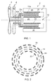
- a turbine 2 comprises a first rotor stage 4 and a second rotor stage 6.
- the first and second rotor stages 4, 6 each comprise a plurality of blades 8a, 8b spaced around the circumference of a shaft 10a, 10b.
- the blades 8a, 8b may have an aerofoil shaped cross-section and, in reaction to the passing wind or water, create a component of force which causes rotation of the rotor stage 4, 6.
- the first and second rotor stages 4, 6 rotate about a common axis with the blades 8a of the first rotor stage 4 preceding the blades 8b of the second rotor stage 6 in the direction of the oncoming wind or water.
- the shaft 10b of the second rotor stage 6 has an aperture formed therethrough for receiving the shaft 10a of the first rotor stage 4, thus allowing rotation about a common axis. Bearings may be provided between the shaft 10a of the first rotor stage 4 and the shaft 10b of the second rotor stage 6.
- the blades 8a, 8b of the first and second rotor stages 4, 6 are configured so that the first rotor stage 4 rotates in the opposite direction to the second rotor stage 6, as indicated by the arrows in Figure 2 . This may be achieved by selecting the appropriate pitch for the blades 8a, 8b of the first and second rotor stages 4, 6.
- the first and second rotor stages 4, 6 further comprise first and second rotor drums 12a, 12b respectively.
- the first and second rotor drums 12a, 12b are connected to and rotated by the blades 8a, 8b via the shafts 10a, 10b.
- each of the first and second rotor drums 12a, 12b are formed from a plurality of elongate pole pieces 14 which are spaced around the circumference of the rotor drum 12a, 12b and extend in an axial direction.
- the pole pieces 14 are passive and are formed from ferromagnetic materials such that they are magnetisable. Adjacent poles pieces 14 are spaced apart from one another.
- the first rotor drum 12a of the first rotor stage 4 has a smaller diameter than the second rotor drum 12b of the second rotor stage 6. Accordingly, the first and second rotor drums 12a, 12b are concentric with the first rotor drum 12a located within the second rotor drum 12b.
- a fixed stator assembly which comprises a first stator member 16 and a second stator member 18.
- the first stator member 16 is formed on a central post 20, around the circumference of which are spaced a plurality of field poles 22.
- Adjacent field poles 22 are spaced apart from one another.
- the field poles 22 may be permanent magnets or electromagnets.
- the field poles 22 are arranged so that adjacent field poles 22 have opposite polarities. Therefore, the polarities of the field poles 22 alternate as you move around the circumference of the central post 20.
- the field poles 22 extend in an axial direction along the length of the central post 20.
- the second stator member 18 encircles the first stator member 16 and is spaced away from the first stator member 16.
- the second stator member 18 is formed on an outer ring 24 and comprises a plurality of power poles 26 spaced around the circumference of an inwardly facing radial surface of the outer ring 24. Adjacent power poles 26 are spaced apart from one another.
- the power poles 26 are conductors or conductive coils which form an armature.
- the power poles 26 extend in an axial direction.
- each field pole 22 of the first stator member 16 and the power poles 26 of the second stator member 18 are arranged in anti-phase, with the field poles 22 offset from the power poles 26. Therefore, in a radial direction each field pole 22 is located opposite to a gap between an adjacent pair of power poles 26, and vice versa. This can be seen more clearly in Figure 3 .
- the space between the first and second stator members 16, 18 is sized to receive the rotor drums 12a, 12b of the first and second rotor stages 4, 6. Accordingly, the first stator member 16 is adjacent to the first rotor drum 12a and the second stator member 18 is adjacent to the second rotor drum 12b.
- the pole pieces 14 of the first and second rotor drums 12a, 12b are at least partially aligned in a radial direction with the field poles 22 and the power poles 26 of the first and second stator members 16, 18 respectively.
- the first stator member 16 may have the same number of field poles 22 as there are power poles 26 on the second stator member 18. Furthermore, the first and second rotor drums 12a, 12b may have the same number of pole pieces 14 and/or the same number of poles pieces as there are field poles 22 or power poles 26.
- the first and second rotor drums 12a, 12b and the first and second stator members 16, 18 form a generator for producing useful power from the action of the wind or water.
- the components of the generator are arranged concentrically with the first stator member 16 forming the innermost element, followed by the first rotor drum 12a, second the rotor drum 12b, and finally the second stator member 18 as the outermost element.
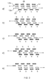
- Figure 3 is a representative view which depicts the circular first and second stator members 16, 18 and the first and second rotor drums 12a, 12b as having been opened out to form linear strips. Having said that, Figure 3 may also be considered to show a linear electrical machine in accordance with another embodiment of the invention. In such an embodiment the "rotors" undergo reciprocating movement in anti-phase.
- Figure 3 shows the movement of the pole pieces 14 of the first and second rotor stages 4, 6 in a series of positions (a) to (e). At position (a) the pole pieces 14 of the first and second rotor stages 4, 6 are in phase and aligned with the power poles 26 of the second stator member 18. In each subsequent position the phase of the pole pieces 14 of the first and second rotor stages 4, 6 are advanced by Pi/8, until at position (e) the pole pieces 14 of both the first and second rotor stages 4, 6 are aligned with the field poles 22 of the first stator member 16.
- the field poles 22 of the first stator member produce a magnetic field. As described previously, this may be by way of a permanent magnet or an electromagnet.
- the pole pieces 14 of the first and second rotor stages 4, 6 act as flux linkage poles which can transmit the magnetic flux from the field poles 22 to the power poles 26 of the second stator member 18 when the pole pieces 14 are appropriately arranged.
- the same pole passing frequency may be achieved by the turbine 2 of the present invention at a quarter of the speed of a conventional turbine. Therefore, the turbine 2 may be made to be four times the diameter i.e. 16 times the area and potentially produce 16 times the power of a conventional turbine.
- the solution alters the compromise between tip speed, rotor diameter, rotor speed and generator diameter to give an alternative optimum commercial solution.
- the first and second rotor drums 12a, 12b have simple passive pole pieces 14 only, and therefore do not require rotating magnets, windings or slip rings etc.
- the field poles 22 and power poles 26 are fixed, the use of electromagnetic windings becomes much more simple and alleviates the need for brushes, slip rings etc.
- the rotors are simple metallic components, construction should be simpler and the components more robust so that clearances and hence magnetic air gaps can be reduced to increase efficiency.
- the present invention allows the generator to be driven directly, it may still be necessary to provide a gearbox arrangement between the first and second rotor stages 4, 6 to synchronise the contra-rotation of the first and second rotor stages 4, 6.
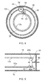
- Such a gearbox arrangement is shown in Figure 4 .
- the embodiment of a gearbox arrangement shown in Figure 4 is an epicyclic gearbox and comprises a fixed outer gear 28 which encircles at least a portion of the first and second rotor drums 12a, 12b.
- the fixed outer gear 28 remains stationary relative to the first and second rotor drums 12a, 12b.
- the fixed outer gear 28 may be located towards the blade-end of the rotor drums i.e. outside of the first and second stator members 16, 18.
- the fixed outer gear 28 comprises teeth 30 on an inwardly facing surface of the gear 28.
- the first rotor drum 12a comprises teeth 32 on an outwardly facing surface of the first rotor drum 12a.
- a first sun gear 34 is rotatably connected to the second rotor drum 12b at a pivot 36.
- the first sun gear 34 has teeth 38 which mesh with the teeth 30 of the fixed outer gear 28.
- a second sun gear 40 is rotatably connected to the second rotor drum 12b either directly or via the first sun gear 34.
- the second sun gear 40 comprises teeth 42 which mesh with the teeth 38 of the first sun gear 34 and the teeth 32 of the first rotor drum 12a.
- Rotation of the second rotor drum 12b causes the first sun gear 34 to rotate in the opposite direction through the interaction of the first sun gear 34 with the fixed outer gear 28.
- the second sun gear 40 is driven in the opposite direction by the first sun gear 34 which in turn drives the first rotor drum 12a.
- first and second rotor drums 12a, 12b are made to rotate synchronously in opposite directions.
- the fixed outer gear 28 has been described as encircling the first and second rotor drums 12a, 12b, it could alternatively have a smaller diameter than the first rotor drum 12a and be located within the first and second rotor drums 12a, 12b. With this arrangement, the first and second sun gears 34 and 40 would be connected to the first rotor drum 12a. Locating the fixed gear within the first rotor drum 12a may allow the gearbox to be made smaller and thus lighter.
- first and second sun gears 34, 40 may be spaced around the circumference of the first and second rotor drums 12a, 12b.
- Figure 5 shows an alternative embodiment of a gearbox arrangement which may be used to synchronise the contra-rotation of the first and second rotor stages 4, 6.
- the gearbox arrangement is located at the free end (i.e. spaced from the blades) of the first and second rotor drums 12a, 12b.
- the first and second rotor drums 12a, 12b may be extended so that the gearbox arrangement can be located away from the field poles 22 and power poles 26 of the first and second stator members 16, 18.
- a fixed idler gear 44 is disposed between the first and second rotor drums 12a, 12b.
- the idler gear 44 is rotatably connected to a bracket 46.
- the idler gear 44 has an axis of rotation which is parallel to the axis of rotation of the first and second rotor drums 12a, 12b.
- the outwardly facing surface of the first rotor drum 12a and the inwardly facing surface of the second rotor drum 12b are provided with teeth 48a, 48b which mesh with the idler gear 44.
- a single idler gear 44 is shown, it may be necessary to use a compound idler gear to provide synchronous rotation of the first and second rotor drums 12a, 12b (see Figure 10 ) where the difference in diameter between the first and second rotor drums 12a, 12b precludes the use of a single idler gear.
- the teeth 48a, 48b each comprise a pair of radial shoulders 50, 52 which axially retain the idler gear 44.
- the rotation of the first rotor drum 12a causes the idler gear 44 to rotate in the same direction, which in turn drives the second rotor drum 12b in the opposite direction, or vice versa.
- idler gear 44 may be spaced around the circumference of the first and second rotor drums 12a, 12b.
- the shoulders 50, 52 retain the idler gear 44 axially, the idler gear 44 may be allowed to translate axially along the bracket 46 to allow the first and second rotor drums 12a, 12b to move in an axial direction.
- the radial shoulders 50, 52 of the teeth 48a, 48b may be omitted to allow axial movement.
- gearbox arrangement may be required to synchronise rotation of the first and second rotor stages 4, 6, it is only necessary for the gearbox to control the difference in torque between the first and second rotor stages 4, 6.
- conventional designs must provide a gearbox which can withstand the total torque.
- the gearbox arrangement may experience high transient loads during use.
- the gearbox would be designed to withstand the maximum load likely to be experienced.
- an overload clutch may be provided to allow non-synchronous movement of the first and second rotor stages 4, 6 under high load conditions.
- FIG. 6 An embodiment of an overload clutch is shown in Figure 6 .
- the overload clutch of Figure 6 is a modification of the epicyclic gearbox arrangement described above with reference to Figure 4 and comprises a fixed outer gear (28, not shown in Figure 6 ) and first and second sun gears 34, 40.
- the overload clutch comprises an intermediate rotor drum 54 disposed between the first and second rotor drums 12a, 12b.
- the intermediate rotor drum 54 which comprises the teeth 32 on an outwardly facing surface, rather than the first rotor drum 12a.
- the teeth 42 of the second sun gear 40 mesh with the teeth 32 of the intermediate rotor drum 54.
- the first rotor drum 12a comprises a plurality of magnets 56 spaced around the circumference of the first rotor drum 12a.
- the intermediate rotor drum 54 comprises a plurality of magnets 58 spaced around the circumference of the intermediate rotor drum 54.
- the number and/or spacing of the magnets 56, 58 on the first rotor drum 12a and the intermediate rotor drum 54 may be equal.
- the magnets 56, 58 of the first rotor drum 12a and the intermediate rotor drum 54 have their magnetic axis (i.e. an axis passing from the North pole of the magnet to the South pole of the magnet) aligned in a radial direction.
- the magnets 56, 58 of the first rotor drum 12a and the intermediate rotor drum 54 are arranged so that they have like-poles at their adjacent ends i.e. the North poles of the magnets 56 of the first rotor drum 12a face outwards and the North poles of the magnets 58 of the intermediate rotor drum 54 face inwards. Consequently, the magnets 56 of the first rotor drum 12a repel the magnets 58 of the intermediate rotor drum 54. As a result, the first rotor drum 12a and the intermediate rotor drum 54 align in the most stable position, this being where the magnets 56 of the first rotor drum 12a are disposed midway between an adjacent pair of magnets 58 of the intermediate rotor drum 54.
- the arrangement of the magnets 56, 58 provides magnetic coupling between the first rotor drum 12a and the intermediate rotor drum 54. Therefore, rotation of the first rotor drum 12a may cause rotation of the intermediate rotor drum 54, and vice versa. In other words, relative rotation of the first rotor drum 12a and the intermediate rotor drum 54 is prevented.
- rotation of the second rotor drum 12b causes the first sun gear 34 to rotate in the opposite direction through the interaction of the first sun gear 34 with the fixed outer gear 28.
- the second sun gear 40 is driven in the opposite direction by the first sun gear 34 which in turn drives the intermediate rotor drum 54. Therefore, the second rotor drum 12b drives the first rotor drum 12a, and vice versa, via the intermediate rotor drum 54.
- the torque between the first rotor drum 12a and the intermediate rotor drum 54 may overcome the repulsive forces thereby allowing non-synchronous movement of the first rotor drum 12a and the intermediate rotor drum 54 and hence of the first rotor drum 12a and the second rotor drum 12b. Whilst the torque exceeds this threshold value, the first rotor drum 12a and the intermediate rotor drum 54 are allowed to rotate relative to one another. However, when the torque falls below the threshold value, the magnets 56, 58 assume the closest stable position with the magnets 56 of the first rotor drum 12a interleaved with the magnets 58 of the intermediate rotor drum 54.
- the magnets 56, 58 of the first rotor drum 12a and the intermediate rotor drum 54 may be arranged so that they have opposite-poles at their adjacent ends i.e. the North poles of the magnets 56 of the first rotor drum 12a face outwards and the South poles of the magnets 58 of the intermediate rotor drum 54 face inwards, or vice versa. Consequently, the magnets 56 of the first rotor drum 12a attract the magnets 58 of the intermediate rotor drum 54. As a result, the first rotor drum 12a and the intermediate rotor drum 54 align in the most stable position, this being where the magnets 56 of the first rotor drum 12a are aligned with magnets 58 of the intermediate rotor drum 54.
- the torque between the first rotor drum 12a and the intermediate rotor drum 54 must overcome the attractive forces between the magnets 56, 58 in order to allow relative rotation between the first rotor drum 12a and the intermediate rotor drum 54.
- the magnets 56, 58 assume the closest stable position with the magnets 56 of the first rotor drum 12a aligned with the magnets 58 of the intermediate rotor drum 54.
- the magnets 56, 58 of the first rotor drum 12a and the intermediate rotor drum 54 are arranged so that in the stable position the first and second rotor drums 12a, 12b are in phase, i.e. the pole pieces 14 of the first and second rotor drums 12a, 12b are aligned or interleaved. Therefore, should relative rotation between the first rotor drum 12a and intermediate rotor drum 54 occur, the next stable position will replicate the previous stable position prior to such relative rotation.
- the fixed outer gear 28 may have a smaller diameter than the first rotor drum 12a and be located within the first and second rotor drums 12a, 12b.
- the first and second sun gears 34 and 40 would be connected to the first rotor drum 12a.
- the magnets 56 are therefore located on the second rotor drum 12b and provide magnetic coupling between the intermediate rotor drum 54 and the second rotor drum 56.
- the intermediate rotor drum 54 could be magnetically coupled to the fixed outer (or inner) gear 28, thus retaining the fixed gear 28 in place whilst the torque is below the threshold value but allowing the fixed gear 28 to rotate when the torque exceeds the threshold value, thereby preventing the fixed gear 28 from rotating the first or second rotor drum 12a, 12b.
- a magnetic gearbox may be used as shown in Figure 7 which provides synchronisation of the first and second rotor drums 12a, 12b and allows non-synchronised movement of the first and second rotor drums 12a, 12b when the torque between the first and second rotor drums 12a, 12b exceeds a threshold value.
- the magnetic gearbox arrangement comprises a plurality of magnets 60 spaced around the circumference of the first rotor drum 12a and a plurality of magnets 62 spaced around the circumference of the second rotor drum 12b.
- the magnets 60, 62 of the first and second rotor drums 12a, 12b are arranged so that the magnets 60, 62 have alternating polarity around the circumference of the first and second rotor drums 12a, 12b (i.e. magnet 60 with inward facing North pole adjacent to a pair of magnets 60 with inward facing South poles).
- a plurality of ferromagnetic pole pieces 64 are disposed between the first and second rotor drums 12a, 12b with their longitudinal axes oriented radially.
- the pole pieces 64 transmit flux between the magnets 60, 62 to control the rotation of the first and second rotor drums 12a, 12b.
- the first and second rotor drums 12a, 12b may be controlled to contra-rotate synchronously.
- the magnetic gearbox also allows non-synchronous rotation when the torque exceeds a threshold value and resumes synchronous movement in phase.
- the first and second rotor drums 12a, 12b are relatively simple generally cylindrical elements with passive pole pieces 14 which transfer flux.
- the pole pieces 14 may be axially aligned and therefore transfer flux between the outer surfaces of the pole pieces 14 of the first rotor drum 12a and the inner surfaces of the pole pieces of the second rotor drum 12b.
- the pole pieces 14 may instead extend in a radial direction with the pole pieces 14 of the first rotor drum 12a extending outwardly and the pole pieces 14 of the second rotor drum 12b extending inwardly.
- flux is transferred between the opposing axial surfaces of the pole pieces 14.
- pole pieces 14 which are laminated to reduce eddy current losses.
- the laminations extend in a radial-axial plane i.e. the direction in which flux travels. Consequently, the pole pieces 14 have a low tolerance to circumferential stresses.
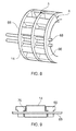
- Figure 8 shows an embodiment of the physical construction of the first or second rotor drum 12a, 12b intended to improve its circumferential strength.
- the rotor drum comprises a plurality of hoops 66 which are spaced from one another in an axial direction.
- the hoops 66 are connected by a plurality of bars 68 which extend in an axial direction and pass through each of the hoops 66 at locations spaced around the circumference of the hoops 66.
- the spacing of the hoops 66 along the bars 68 may be fixed using conventional techniques, such as bolts, welding, etc.
- the pole pieces 14 are disposed between adjacent hoops 66.
- the pole pieces 14 are connected to the hoops 66 and/or bars 68 using an inference fit, for example.
- the hoops thereby provide circumferential strength to the pole pieces 14.
- Figure 9 shows a cross-section through the plane A-A of Figure 8 .
- the hoops 66 may be provided with axial shoulders 70 and the pole pieces 14 may be provided with corresponding axial recesses which abut with the axial shoulders 70 when the pole pieces 14 are located between the hoops 66.
- the shoulders 70 of the hoops 66 act to retain the pole pieces 14 when under centrifugal loading.
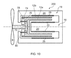
- FIG. 10 An alternative embodiment of the turbine is shown in Figure 10 .
- the turbine 200 of this embodiment has blades 8 only on the first rotor stage 4. In reaction to the passing wind or water, the blades 8 create a component of force which causes rotation of the first rotor stage 4.
- the second rotor stage 6 is not driven directly by the wind or water and therefore does not have any blades.
- the second rotor stage comprises only the second rotor drum 12b which is driven by the rotation of the first rotor stage 4.
- the second rotor drum 12b is made to rotate in the opposite direction to the first rotor drum 12a using a gearbox arrangement.
- the gearbox arrangement may be as described previously with respect to Figures 4 to 7 .
- the shaft 10a may comprise a gear 72 located between the blades 8 and the first rotor drum 12a.
- the gear 72 drives the second rotor drum 12b via a fixed compound idler 74.
- the fixed compound idler 74 comprises a smaller gear 76 and a larger gear 78.
- the fixed compound idler 74 is rotatably connected to the casing of the generator by a bracket 80.
- the fixed compound idler 74 therefore has an axis of rotation which is parallel to the axis of rotation of the first and second rotor drums 12a, 12b.
- the smaller gear 76 is driven by the gear 72 and the larger gear 78 drives the second rotor drum 12b.
- the fixed compound gear 74 therefore provides contra-rotation of the first and second rotor drums 12a, 12b and compensates for the difference in diameter (and hence number of teeth) between the gear 72 and the second rotor drum 12b.
- the rotors may have different numbers of poles provided that the pole passing frequency and phase are maintained.
- the gearing shown in Figure 5 will result in the pole pieces of the outer rotor 12b moving at the same linear speed as pole pieces of rotor 12a, but with the outer rotor having a slower rotational speed.
- the outer rotor 12b may include more pole pieces than the inner rotor provided the gearing is appropriately selected to maintain the pole passing frequency required by the electromagnetic relationship of the components required for generation and as described above.
- the second rotor drum 12b may be driven directly by the wind or water and the first rotor drum 12a driven indirectly via the second rotor drum 12a.
- one or more helical poles may be provided in the first rotor drum 12a, second rotor drum 12b, first stator member 16 and/or second stator member 18.
- the first and second rotor drums 12a, 12b and the first and second stator members 16, 18 may be provided with several sets of poles.
- the sets of poles are spaced along the generator in an axial direction to effectively define a plurality of generators.
- the poles of one generator are staggered from the poles of the or each other generator in a circumferential direction. This arrangement provides even torque throughout the rotation of the first and second rotor drums 12a, 12b.
- the plurality of sets of poles may also be used to provide a polyphase system i.e. 3-phase.
- first and second rotor stages 4, 6 and first and second rotor drums 12a, 12b it could have more than two rotor stages and/or rotor drums. Each additional rotor drum will increase the pole passing frequency by two times the number of rotor drums.
- the invention is not limited to a horizontal axis turbine as shown, but could instead be used with a vertical axis turbine.
- the generator of the present invention is not restricted to wind or water turbines, but could be used in other situations where contra-rotating power is available.
- the present invention has been described with reference to a generator, it could be utilised in other electrical machines.
- the invention could be used as a motor. This may be particularly useful for providing power to contra-rotating props on an electrically powered aircraft or boat.
Landscapes
- Engineering & Computer Science (AREA)
- Power Engineering (AREA)
- Life Sciences & Earth Sciences (AREA)
- Sustainable Energy (AREA)
- Sustainable Development (AREA)
- Permanent Magnet Type Synchronous Machine (AREA)
- Connection Of Motors, Electrical Generators, Mechanical Devices, And The Like (AREA)
- Permanent Field Magnets Of Synchronous Machinery (AREA)
- Dynamo-Electric Clutches, Dynamo-Electric Brakes (AREA)
Applications Claiming Priority (1)
| Application Number | Priority Date | Filing Date | Title |
|---|---|---|---|
| GBGB1110640.8A GB201110640D0 (en) | 2011-06-23 | 2011-06-23 | An electrical machine with contra-rotating rotors |
Publications (3)
| Publication Number | Publication Date |
|---|---|
| EP2538529A2 true EP2538529A2 (de) | 2012-12-26 |
| EP2538529A3 EP2538529A3 (de) | 2016-02-24 |
| EP2538529B1 EP2538529B1 (de) | 2019-08-07 |
Family
ID=44485022
Family Applications (1)
| Application Number | Title | Priority Date | Filing Date |
|---|---|---|---|
| EP12172351.4A Active EP2538529B1 (de) | 2011-06-23 | 2012-06-18 | Elektrische Maschine mit gegenläufigen Rotoren |
Country Status (3)
| Country | Link |
|---|---|
| US (1) | US9184649B2 (de) |
| EP (1) | EP2538529B1 (de) |
| GB (1) | GB201110640D0 (de) |
Cited By (1)
| Publication number | Priority date | Publication date | Assignee | Title |
|---|---|---|---|---|
| DE102017100674A1 (de) | 2017-01-16 | 2018-07-19 | Vladimir Schmidt | Strömungsenergieanlage |
Families Citing this family (19)
| Publication number | Priority date | Publication date | Assignee | Title |
|---|---|---|---|---|
| AT514240B1 (de) * | 2013-04-22 | 2015-02-15 | Hitzinger Gmbh | Energiespeicher und Vorrichtung zur unterbrechungsfreien Energieversorgung |
| IL230934A (en) * | 2014-02-12 | 2017-03-30 | Doron Eliahu Ezoory | Turbine for energy production |
| EP3035504B1 (de) * | 2014-12-18 | 2017-07-26 | Rolls-Royce plc | Elektrische maschinen |
| US10116187B1 (en) * | 2015-10-02 | 2018-10-30 | Cr Flight Llc | Thin-profile counter-rotating differential electric motor assembly |
| TW201715150A (zh) * | 2015-10-27 | 2017-05-01 | guo-zhang Huang | 流力發電裝置 |
| WO2018018094A1 (en) * | 2016-07-28 | 2018-02-01 | Manuel Vieira Barreiro | Double-action electricity generator |
| US20190093746A1 (en) * | 2017-09-22 | 2019-03-28 | Exedy Corporation | Dynamic damper device |
| US10715019B2 (en) * | 2018-05-18 | 2020-07-14 | Kohler Co. | Dual axis motor |
| US11052997B2 (en) * | 2018-12-21 | 2021-07-06 | Peng Yu Huang | Dual-rotor wing motor |
| GB201902095D0 (en) * | 2019-02-15 | 2019-04-03 | Rolls Royce Plc | Electric turbomachine |
| US11329537B2 (en) * | 2019-05-02 | 2022-05-10 | X Development Llc | Super-synchronous motor/generator |
| US11046404B2 (en) * | 2019-07-31 | 2021-06-29 | Abb Schweiz Ag | Dual propeller drive system for a ship |
| RU203894U1 (ru) * | 2020-12-16 | 2021-04-26 | Александр Александрович Стуров | Электромашина Стурова с наружным и внутренним статорами, вращением соосных со статорами роторов в противоположных направлениях |
| RU204090U1 (ru) * | 2021-01-19 | 2021-05-06 | Александр Александрович Стуров | Электромашина Стурова с наружным и внутренним статорами, вращением соосных со статорами роторов в противоположных направлениях |
| FR3130357A1 (fr) * | 2021-12-15 | 2023-06-16 | Ubiblue | Générateur magnétocalorique à efficacité augmentée |
| DE102022133327A1 (de) * | 2022-12-14 | 2024-06-20 | Guido Henrici | Antriebsstrang mit einer Vorrichtung zur wahlweisen Erzeugung eines elektromotorisch einstellbaren Antriebsmoments |
| GB2634497A (en) * | 2023-10-04 | 2025-04-16 | World Wide Wind Tech As | A device, system, and method for controlling a rotational arrangement, and use of such device and system |
| US20250283435A1 (en) * | 2024-03-06 | 2025-09-11 | General Electric Company | Power transfer system for a gas turbine engine |
| KR102816929B1 (ko) * | 2024-05-09 | 2025-06-04 | 한국해양과학기술원 | 상반회전추진기의 선체 직결형 추진 장치 및 그 제조방법 |
Family Cites Families (21)
| Publication number | Priority date | Publication date | Assignee | Title |
|---|---|---|---|---|
| GB191514643A (en) * | 1915-10-16 | 1916-10-16 | Frank Arthur Heys | Improvements in Dynamo Electric Machines. |
| GB1196213A (en) * | 1968-04-30 | 1970-06-24 | Alexandr Sergeevich Kurakin | Low-Speed Synchronous Electric Motor |
| US3603823A (en) * | 1969-12-09 | 1971-09-07 | Elmer B Mason | Magnetic motor with plurality of stators |
| US3646375A (en) * | 1970-12-30 | 1972-02-29 | Dale Electronics | Motorized potentiometer with overload clutch and interchangeable gear ratio |
| US3956678A (en) * | 1972-03-01 | 1976-05-11 | John Byrne | Electrodynamic system comprising a variable reluctance machine |
| GB1475687A (en) * | 1973-05-25 | 1977-06-01 | Int Research & Dev Co Ltd | Homopolar dynamo-electric machines |
| GB2062977B (en) * | 1979-11-10 | 1984-08-30 | Northern Eng Ind | Alternator |
| US4441043A (en) * | 1980-11-24 | 1984-04-03 | Decesare Dominic | Compound interaction/induction electric rotating machine |
| GB2186342A (en) * | 1986-02-06 | 1987-08-12 | Johnson Electric Ind Mfg | An electric motor and gearbox unit and component parts thereof |
| DE3612741A1 (de) * | 1986-04-16 | 1987-10-22 | Porsche Ag | Sperrsynchronisiereinrichtung fuer ein zahnraederwechselgetriebe eines kraftfahrzeugs |
| JP2000350309A (ja) * | 1999-06-04 | 2000-12-15 | Denso Corp | 動力変換装置ならびに車両用駆動装置 |
| DE10250382A1 (de) * | 2002-10-29 | 2004-05-19 | Siemens Ag | Drehstrom-Asynchrongenerator |
| US7199484B2 (en) * | 2005-07-05 | 2007-04-03 | Gencor Industries Inc. | Water current generator |
| DE102007001828A1 (de) * | 2007-01-12 | 2008-07-17 | Siemens Ag | Getriebeeinrichtung mit einem inneren und einem äußeren Rotorteil, welche von einem inneren und einem äußeren Statorteil umgeben sind |
| US7679249B2 (en) * | 2007-03-02 | 2010-03-16 | Kari Appa | Contra rotating generator |
| GB0720475D0 (en) * | 2007-10-18 | 2007-11-28 | Rolls Royce Plc | A magnetic harmonic gearbox |
| JP2009202439A (ja) | 2008-02-28 | 2009-09-10 | Seiko Epson Corp | 流体噴射装置 |
| JP2009254021A (ja) * | 2008-04-01 | 2009-10-29 | Asmo Co Ltd | 電動機 |
| GB0809247D0 (en) * | 2008-05-22 | 2008-06-25 | Rolls Royce Plc | An electrical generator arrangement |
| JP5109917B2 (ja) * | 2008-10-10 | 2012-12-26 | 株式会社デンソー | 回転電機 |
| US8063528B2 (en) * | 2009-12-18 | 2011-11-22 | General Electric Company | Counter-rotatable generator |
-
2011
- 2011-06-23 GB GBGB1110640.8A patent/GB201110640D0/en not_active Ceased
-
2012
- 2012-06-18 EP EP12172351.4A patent/EP2538529B1/de active Active
- 2012-06-18 US US13/525,660 patent/US9184649B2/en active Active
Non-Patent Citations (1)
| Title |
|---|
| None |
Cited By (1)
| Publication number | Priority date | Publication date | Assignee | Title |
|---|---|---|---|---|
| DE102017100674A1 (de) | 2017-01-16 | 2018-07-19 | Vladimir Schmidt | Strömungsenergieanlage |
Also Published As
| Publication number | Publication date |
|---|---|
| US9184649B2 (en) | 2015-11-10 |
| US20120326539A1 (en) | 2012-12-27 |
| EP2538529A3 (de) | 2016-02-24 |
| EP2538529B1 (de) | 2019-08-07 |
| GB201110640D0 (en) | 2011-08-10 |
Similar Documents
| Publication | Publication Date | Title |
|---|---|---|
| US9184649B2 (en) | Electrical machine with contra-rotating rotors | |
| US7960887B2 (en) | Permanent-magnet switched-flux machine | |
| US8358044B2 (en) | Electric machine apparatus with integrated, high torque density magnetic gearing | |
| EP1353436B1 (de) | Kompakte elektrische Maschine | |
| EP2133982A2 (de) | Elektrische Maschine mit integriertem magnetischen Getriebe | |
| CN102647058A (zh) | 电力设备 | |
| Uppalapati et al. | Performance of a magnetic gear using ferrite magnets for low speed ocean power generation | |
| US10476349B2 (en) | Method and apparatus for compact axial flux magnetically geared machines | |
| US6762523B1 (en) | Continuously variable electromagnetic transmission | |
| US8461730B2 (en) | Radial flux permanent magnet alternator with dielectric stator block | |
| NO337848B1 (no) | Elektrisk maskin | |
| US10523098B1 (en) | Progressive magnetic rotation motor | |
| EP2528207A1 (de) | Bürstenlose elektrische Maschine | |
| EP3455922B1 (de) | Paare aus komplementär unidirektional magnetischen rotor-/statoranordnungen | |
| CN104953779A (zh) | 磁性齿轮低速大转矩电机 | |
| EP3017529B1 (de) | Reduzierung der lagerkräfte bei einer elektrischen maschine | |
| EP3696388B1 (de) | Elektrische turbomaschine | |
| WO2009050421A1 (en) | A magnetic harmonic gearbox | |
| JP6572421B2 (ja) | アキシャル型磁気ギヤード電機 | |
| RU105089U1 (ru) | Электрическая машина | |
| CN116846138A (zh) | 同步逆向高底速发电机 | |
| WO2016072834A2 (en) | Energy convertor | |
| CN120476533A (zh) | 电动机(ii) | |
| RU102157U1 (ru) | Электродвигатель мельницы самоизмельчения алмазосодержащих руд | |
| RU102156U1 (ru) | Электродвигатель мельницы самоизмельчения алмазосодержащих руд |
Legal Events
| Date | Code | Title | Description |
|---|---|---|---|
| PUAI | Public reference made under article 153(3) epc to a published international application that has entered the european phase |
Free format text: ORIGINAL CODE: 0009012 |
|
| AK | Designated contracting states |
Kind code of ref document: A2 Designated state(s): AL AT BE BG CH CY CZ DE DK EE ES FI FR GB GR HR HU IE IS IT LI LT LU LV MC MK MT NL NO PL PT RO RS SE SI SK SM TR |
|
| AX | Request for extension of the european patent |
Extension state: BA ME |
|
| RAP1 | Party data changed (applicant data changed or rights of an application transferred) |
Owner name: ROLLS-ROYCE PLC |
|
| PUAL | Search report despatched |
Free format text: ORIGINAL CODE: 0009013 |
|
| AK | Designated contracting states |
Kind code of ref document: A3 Designated state(s): AL AT BE BG CH CY CZ DE DK EE ES FI FR GB GR HR HU IE IS IT LI LT LU LV MC MK MT NL NO PL PT RO RS SE SI SK SM TR |
|
| AX | Request for extension of the european patent |
Extension state: BA ME |
|
| RIC1 | Information provided on ipc code assigned before grant |
Ipc: H02K 19/24 20060101ALI20160115BHEP Ipc: H02K 19/10 20060101ALI20160115BHEP Ipc: H02K 21/38 20060101ALI20160115BHEP Ipc: H02K 19/06 20060101ALI20160115BHEP Ipc: H02K 16/00 20060101AFI20160115BHEP |
|
| 17P | Request for examination filed |
Effective date: 20160823 |
|
| RBV | Designated contracting states (corrected) |
Designated state(s): AL AT BE BG CH CY CZ DE DK EE ES FI FR GB GR HR HU IE IS IT LI LT LU LV MC MK MT NL NO PL PT RO RS SE SI SK SM TR |
|
| STAA | Information on the status of an ep patent application or granted ep patent |
Free format text: STATUS: EXAMINATION IS IN PROGRESS |
|
| 17Q | First examination report despatched |
Effective date: 20170620 |
|
| RIC1 | Information provided on ipc code assigned before grant |
Ipc: H02K 7/116 20060101ALN20190130BHEP Ipc: H02K 21/38 20060101ALN20190130BHEP Ipc: H02K 19/06 20060101ALN20190130BHEP Ipc: H02K 7/11 20060101ALN20190130BHEP Ipc: H02K 19/10 20060101ALN20190130BHEP Ipc: H02K 21/40 20060101ALN20190130BHEP Ipc: H02K 16/00 20060101AFI20190130BHEP Ipc: H02K 21/42 20060101ALN20190130BHEP Ipc: H02K 19/24 20060101ALN20190130BHEP Ipc: H02K 7/18 20060101ALI20190130BHEP |
|
| RIC1 | Information provided on ipc code assigned before grant |
Ipc: H02K 7/18 20060101ALI20190213BHEP Ipc: H02K 16/00 20060101AFI20190213BHEP Ipc: H02K 21/42 20060101ALN20190213BHEP Ipc: H02K 19/06 20060101ALN20190213BHEP Ipc: H02K 19/24 20060101ALN20190213BHEP Ipc: H02K 7/116 20060101ALN20190213BHEP Ipc: H02K 21/38 20060101ALN20190213BHEP Ipc: H02K 19/10 20060101ALN20190213BHEP Ipc: H02K 21/40 20060101ALN20190213BHEP Ipc: H02K 7/11 20060101ALN20190213BHEP |
|
| GRAP | Despatch of communication of intention to grant a patent |
Free format text: ORIGINAL CODE: EPIDOSNIGR1 |
|
| STAA | Information on the status of an ep patent application or granted ep patent |
Free format text: STATUS: GRANT OF PATENT IS INTENDED |
|
| RIC1 | Information provided on ipc code assigned before grant |
Ipc: H02K 21/42 20060101ALN20190321BHEP Ipc: H02K 19/06 20060101ALN20190321BHEP Ipc: H02K 19/10 20060101ALN20190321BHEP Ipc: H02K 7/11 20060101ALN20190321BHEP Ipc: H02K 19/24 20060101ALN20190321BHEP Ipc: H02K 16/00 20060101AFI20190321BHEP Ipc: H02K 7/116 20060101ALN20190321BHEP Ipc: H02K 21/38 20060101ALN20190321BHEP Ipc: H02K 21/40 20060101ALN20190321BHEP Ipc: H02K 7/18 20060101ALI20190321BHEP |
|
| INTG | Intention to grant announced |
Effective date: 20190402 |
|
| GRAS | Grant fee paid |
Free format text: ORIGINAL CODE: EPIDOSNIGR3 |
|
| GRAA | (expected) grant |
Free format text: ORIGINAL CODE: 0009210 |
|
| STAA | Information on the status of an ep patent application or granted ep patent |
Free format text: STATUS: THE PATENT HAS BEEN GRANTED |
|
| AK | Designated contracting states |
Kind code of ref document: B1 Designated state(s): AL AT BE BG CH CY CZ DE DK EE ES FI FR GB GR HR HU IE IS IT LI LT LU LV MC MK MT NL NO PL PT RO RS SE SI SK SM TR |
|
| REG | Reference to a national code |
Ref country code: GB Ref legal event code: FG4D |
|
| REG | Reference to a national code |
Ref country code: CH Ref legal event code: EP Ref country code: AT Ref legal event code: REF Ref document number: 1165326 Country of ref document: AT Kind code of ref document: T Effective date: 20190815 |
|
| REG | Reference to a national code |
Ref country code: DE Ref legal event code: R096 Ref document number: 602012062619 Country of ref document: DE |
|
| REG | Reference to a national code |
Ref country code: IE Ref legal event code: FG4D |
|
| REG | Reference to a national code |
Ref country code: NL Ref legal event code: MP Effective date: 20190807 |
|
| REG | Reference to a national code |
Ref country code: LT Ref legal event code: MG4D |
|
| PG25 | Lapsed in a contracting state [announced via postgrant information from national office to epo] |
Ref country code: FI Free format text: LAPSE BECAUSE OF FAILURE TO SUBMIT A TRANSLATION OF THE DESCRIPTION OR TO PAY THE FEE WITHIN THE PRESCRIBED TIME-LIMIT Effective date: 20190807 Ref country code: NO Free format text: LAPSE BECAUSE OF FAILURE TO SUBMIT A TRANSLATION OF THE DESCRIPTION OR TO PAY THE FEE WITHIN THE PRESCRIBED TIME-LIMIT Effective date: 20191107 Ref country code: SE Free format text: LAPSE BECAUSE OF FAILURE TO SUBMIT A TRANSLATION OF THE DESCRIPTION OR TO PAY THE FEE WITHIN THE PRESCRIBED TIME-LIMIT Effective date: 20190807 Ref country code: NL Free format text: LAPSE BECAUSE OF FAILURE TO SUBMIT A TRANSLATION OF THE DESCRIPTION OR TO PAY THE FEE WITHIN THE PRESCRIBED TIME-LIMIT Effective date: 20190807 Ref country code: BG Free format text: LAPSE BECAUSE OF FAILURE TO SUBMIT A TRANSLATION OF THE DESCRIPTION OR TO PAY THE FEE WITHIN THE PRESCRIBED TIME-LIMIT Effective date: 20191107 Ref country code: LT Free format text: LAPSE BECAUSE OF FAILURE TO SUBMIT A TRANSLATION OF THE DESCRIPTION OR TO PAY THE FEE WITHIN THE PRESCRIBED TIME-LIMIT Effective date: 20190807 Ref country code: PT Free format text: LAPSE BECAUSE OF FAILURE TO SUBMIT A TRANSLATION OF THE DESCRIPTION OR TO PAY THE FEE WITHIN THE PRESCRIBED TIME-LIMIT Effective date: 20191209 Ref country code: HR Free format text: LAPSE BECAUSE OF FAILURE TO SUBMIT A TRANSLATION OF THE DESCRIPTION OR TO PAY THE FEE WITHIN THE PRESCRIBED TIME-LIMIT Effective date: 20190807 |
|
| REG | Reference to a national code |
Ref country code: AT Ref legal event code: MK05 Ref document number: 1165326 Country of ref document: AT Kind code of ref document: T Effective date: 20190807 |
|
| RAP2 | Party data changed (patent owner data changed or rights of a patent transferred) |
Owner name: ROLLS-ROYCE PLC |
|
| PG25 | Lapsed in a contracting state [announced via postgrant information from national office to epo] |
Ref country code: RS Free format text: LAPSE BECAUSE OF FAILURE TO SUBMIT A TRANSLATION OF THE DESCRIPTION OR TO PAY THE FEE WITHIN THE PRESCRIBED TIME-LIMIT Effective date: 20190807 Ref country code: IS Free format text: LAPSE BECAUSE OF FAILURE TO SUBMIT A TRANSLATION OF THE DESCRIPTION OR TO PAY THE FEE WITHIN THE PRESCRIBED TIME-LIMIT Effective date: 20191207 Ref country code: GR Free format text: LAPSE BECAUSE OF FAILURE TO SUBMIT A TRANSLATION OF THE DESCRIPTION OR TO PAY THE FEE WITHIN THE PRESCRIBED TIME-LIMIT Effective date: 20191108 Ref country code: ES Free format text: LAPSE BECAUSE OF FAILURE TO SUBMIT A TRANSLATION OF THE DESCRIPTION OR TO PAY THE FEE WITHIN THE PRESCRIBED TIME-LIMIT Effective date: 20190807 Ref country code: AL Free format text: LAPSE BECAUSE OF FAILURE TO SUBMIT A TRANSLATION OF THE DESCRIPTION OR TO PAY THE FEE WITHIN THE PRESCRIBED TIME-LIMIT Effective date: 20190807 Ref country code: LV Free format text: LAPSE BECAUSE OF FAILURE TO SUBMIT A TRANSLATION OF THE DESCRIPTION OR TO PAY THE FEE WITHIN THE PRESCRIBED TIME-LIMIT Effective date: 20190807 |
|
| PG25 | Lapsed in a contracting state [announced via postgrant information from national office to epo] |
Ref country code: TR Free format text: LAPSE BECAUSE OF FAILURE TO SUBMIT A TRANSLATION OF THE DESCRIPTION OR TO PAY THE FEE WITHIN THE PRESCRIBED TIME-LIMIT Effective date: 20190807 |
|
| PG25 | Lapsed in a contracting state [announced via postgrant information from national office to epo] |
Ref country code: EE Free format text: LAPSE BECAUSE OF FAILURE TO SUBMIT A TRANSLATION OF THE DESCRIPTION OR TO PAY THE FEE WITHIN THE PRESCRIBED TIME-LIMIT Effective date: 20190807 Ref country code: DK Free format text: LAPSE BECAUSE OF FAILURE TO SUBMIT A TRANSLATION OF THE DESCRIPTION OR TO PAY THE FEE WITHIN THE PRESCRIBED TIME-LIMIT Effective date: 20190807 Ref country code: PL Free format text: LAPSE BECAUSE OF FAILURE TO SUBMIT A TRANSLATION OF THE DESCRIPTION OR TO PAY THE FEE WITHIN THE PRESCRIBED TIME-LIMIT Effective date: 20190807 Ref country code: RO Free format text: LAPSE BECAUSE OF FAILURE TO SUBMIT A TRANSLATION OF THE DESCRIPTION OR TO PAY THE FEE WITHIN THE PRESCRIBED TIME-LIMIT Effective date: 20190807 Ref country code: IT Free format text: LAPSE BECAUSE OF FAILURE TO SUBMIT A TRANSLATION OF THE DESCRIPTION OR TO PAY THE FEE WITHIN THE PRESCRIBED TIME-LIMIT Effective date: 20190807 Ref country code: AT Free format text: LAPSE BECAUSE OF FAILURE TO SUBMIT A TRANSLATION OF THE DESCRIPTION OR TO PAY THE FEE WITHIN THE PRESCRIBED TIME-LIMIT Effective date: 20190807 |
|
| PG25 | Lapsed in a contracting state [announced via postgrant information from national office to epo] |
Ref country code: SK Free format text: LAPSE BECAUSE OF FAILURE TO SUBMIT A TRANSLATION OF THE DESCRIPTION OR TO PAY THE FEE WITHIN THE PRESCRIBED TIME-LIMIT Effective date: 20190807 Ref country code: IS Free format text: LAPSE BECAUSE OF FAILURE TO SUBMIT A TRANSLATION OF THE DESCRIPTION OR TO PAY THE FEE WITHIN THE PRESCRIBED TIME-LIMIT Effective date: 20200224 Ref country code: CZ Free format text: LAPSE BECAUSE OF FAILURE TO SUBMIT A TRANSLATION OF THE DESCRIPTION OR TO PAY THE FEE WITHIN THE PRESCRIBED TIME-LIMIT Effective date: 20190807 Ref country code: SM Free format text: LAPSE BECAUSE OF FAILURE TO SUBMIT A TRANSLATION OF THE DESCRIPTION OR TO PAY THE FEE WITHIN THE PRESCRIBED TIME-LIMIT Effective date: 20190807 |
|
| REG | Reference to a national code |
Ref country code: DE Ref legal event code: R097 Ref document number: 602012062619 Country of ref document: DE |
|
| PLBE | No opposition filed within time limit |
Free format text: ORIGINAL CODE: 0009261 |
|
| STAA | Information on the status of an ep patent application or granted ep patent |
Free format text: STATUS: NO OPPOSITION FILED WITHIN TIME LIMIT |
|
| PG2D | Information on lapse in contracting state deleted |
Ref country code: IS |
|
| 26N | No opposition filed |
Effective date: 20200603 |
|
| PG25 | Lapsed in a contracting state [announced via postgrant information from national office to epo] |
Ref country code: SI Free format text: LAPSE BECAUSE OF FAILURE TO SUBMIT A TRANSLATION OF THE DESCRIPTION OR TO PAY THE FEE WITHIN THE PRESCRIBED TIME-LIMIT Effective date: 20190807 |
|
| PG25 | Lapsed in a contracting state [announced via postgrant information from national office to epo] |
Ref country code: MC Free format text: LAPSE BECAUSE OF FAILURE TO SUBMIT A TRANSLATION OF THE DESCRIPTION OR TO PAY THE FEE WITHIN THE PRESCRIBED TIME-LIMIT Effective date: 20190807 |
|
| REG | Reference to a national code |
Ref country code: CH Ref legal event code: PL |
|
| PG25 | Lapsed in a contracting state [announced via postgrant information from national office to epo] |
Ref country code: LU Free format text: LAPSE BECAUSE OF NON-PAYMENT OF DUE FEES Effective date: 20200618 |
|
| REG | Reference to a national code |
Ref country code: BE Ref legal event code: MM Effective date: 20200630 |
|
| PG25 | Lapsed in a contracting state [announced via postgrant information from national office to epo] |
Ref country code: IE Free format text: LAPSE BECAUSE OF NON-PAYMENT OF DUE FEES Effective date: 20200618 Ref country code: LI Free format text: LAPSE BECAUSE OF NON-PAYMENT OF DUE FEES Effective date: 20200630 Ref country code: CH Free format text: LAPSE BECAUSE OF NON-PAYMENT OF DUE FEES Effective date: 20200630 |
|
| PG25 | Lapsed in a contracting state [announced via postgrant information from national office to epo] |
Ref country code: BE Free format text: LAPSE BECAUSE OF NON-PAYMENT OF DUE FEES Effective date: 20200630 |
|
| PG25 | Lapsed in a contracting state [announced via postgrant information from national office to epo] |
Ref country code: MT Free format text: LAPSE BECAUSE OF FAILURE TO SUBMIT A TRANSLATION OF THE DESCRIPTION OR TO PAY THE FEE WITHIN THE PRESCRIBED TIME-LIMIT Effective date: 20190807 Ref country code: CY Free format text: LAPSE BECAUSE OF FAILURE TO SUBMIT A TRANSLATION OF THE DESCRIPTION OR TO PAY THE FEE WITHIN THE PRESCRIBED TIME-LIMIT Effective date: 20190807 |
|
| PG25 | Lapsed in a contracting state [announced via postgrant information from national office to epo] |
Ref country code: MK Free format text: LAPSE BECAUSE OF FAILURE TO SUBMIT A TRANSLATION OF THE DESCRIPTION OR TO PAY THE FEE WITHIN THE PRESCRIBED TIME-LIMIT Effective date: 20190807 |
|
| P01 | Opt-out of the competence of the unified patent court (upc) registered |
Effective date: 20230528 |
|
| PGFP | Annual fee paid to national office [announced via postgrant information from national office to epo] |
Ref country code: DE Payment date: 20250626 Year of fee payment: 14 |
|
| PGFP | Annual fee paid to national office [announced via postgrant information from national office to epo] |
Ref country code: GB Payment date: 20250617 Year of fee payment: 14 |
|
| PGFP | Annual fee paid to national office [announced via postgrant information from national office to epo] |
Ref country code: FR Payment date: 20250624 Year of fee payment: 14 |