EP2538103A1 - Clutch unit - Google Patents
Clutch unit Download PDFInfo
- Publication number
- EP2538103A1 EP2538103A1 EP11744572A EP11744572A EP2538103A1 EP 2538103 A1 EP2538103 A1 EP 2538103A1 EP 11744572 A EP11744572 A EP 11744572A EP 11744572 A EP11744572 A EP 11744572A EP 2538103 A1 EP2538103 A1 EP 2538103A1
- Authority
- EP
- European Patent Office
- Prior art keywords
- input
- lever
- side member
- torque
- output
- Prior art date
- Legal status (The legal status is an assumption and is not a legal conclusion. Google has not performed a legal analysis and makes no representation as to the accuracy of the status listed.)
- Granted
Links
Images













Classifications
-
- F—MECHANICAL ENGINEERING; LIGHTING; HEATING; WEAPONS; BLASTING
- F16—ENGINEERING ELEMENTS AND UNITS; GENERAL MEASURES FOR PRODUCING AND MAINTAINING EFFECTIVE FUNCTIONING OF MACHINES OR INSTALLATIONS; THERMAL INSULATION IN GENERAL
- F16D—COUPLINGS FOR TRANSMITTING ROTATION; CLUTCHES; BRAKES
- F16D41/00—Freewheels or freewheel clutches
- F16D41/06—Freewheels or freewheel clutches with intermediate wedging coupling members between an inner and an outer surface
- F16D41/08—Freewheels or freewheel clutches with intermediate wedging coupling members between an inner and an outer surface with provision for altering the freewheeling action
- F16D41/10—Freewheels or freewheel clutches with intermediate wedging coupling members between an inner and an outer surface with provision for altering the freewheeling action with self-actuated reversing
- F16D41/105—Freewheels or freewheel clutches with intermediate wedging coupling members between an inner and an outer surface with provision for altering the freewheeling action with self-actuated reversing the intermediate members being of circular cross-section, of only one size and wedging by rolling movement not having an axial component between inner and outer races, one of which is cylindrical
-
- B—PERFORMING OPERATIONS; TRANSPORTING
- B60—VEHICLES IN GENERAL
- B60N—SEATS SPECIALLY ADAPTED FOR VEHICLES; VEHICLE PASSENGER ACCOMMODATION NOT OTHERWISE PROVIDED FOR
- B60N2/00—Seats specially adapted for vehicles; Arrangement or mounting of seats in vehicles
- B60N2/02—Seats specially adapted for vehicles; Arrangement or mounting of seats in vehicles the seat or part thereof being movable, e.g. adjustable
- B60N2/04—Seats specially adapted for vehicles; Arrangement or mounting of seats in vehicles the seat or part thereof being movable, e.g. adjustable the whole seat being movable
- B60N2/16—Seats specially adapted for vehicles; Arrangement or mounting of seats in vehicles the seat or part thereof being movable, e.g. adjustable the whole seat being movable height-adjustable
- B60N2/1605—Seats specially adapted for vehicles; Arrangement or mounting of seats in vehicles the seat or part thereof being movable, e.g. adjustable the whole seat being movable height-adjustable characterised by the cinematic
- B60N2/161—Rods
- B60N2/1615—Parallelogram-like structure
-
- B—PERFORMING OPERATIONS; TRANSPORTING
- B60—VEHICLES IN GENERAL
- B60N—SEATS SPECIALLY ADAPTED FOR VEHICLES; VEHICLE PASSENGER ACCOMMODATION NOT OTHERWISE PROVIDED FOR
- B60N2/00—Seats specially adapted for vehicles; Arrangement or mounting of seats in vehicles
- B60N2/02—Seats specially adapted for vehicles; Arrangement or mounting of seats in vehicles the seat or part thereof being movable, e.g. adjustable
- B60N2/04—Seats specially adapted for vehicles; Arrangement or mounting of seats in vehicles the seat or part thereof being movable, e.g. adjustable the whole seat being movable
- B60N2/16—Seats specially adapted for vehicles; Arrangement or mounting of seats in vehicles the seat or part thereof being movable, e.g. adjustable the whole seat being movable height-adjustable
- B60N2/1635—Seats specially adapted for vehicles; Arrangement or mounting of seats in vehicles the seat or part thereof being movable, e.g. adjustable the whole seat being movable height-adjustable characterised by the drive mechanism
- B60N2/167—Ratchet mechanism
-
- B—PERFORMING OPERATIONS; TRANSPORTING
- B60—VEHICLES IN GENERAL
- B60N—SEATS SPECIALLY ADAPTED FOR VEHICLES; VEHICLE PASSENGER ACCOMMODATION NOT OTHERWISE PROVIDED FOR
- B60N2/00—Seats specially adapted for vehicles; Arrangement or mounting of seats in vehicles
- B60N2/02—Seats specially adapted for vehicles; Arrangement or mounting of seats in vehicles the seat or part thereof being movable, e.g. adjustable
- B60N2/04—Seats specially adapted for vehicles; Arrangement or mounting of seats in vehicles the seat or part thereof being movable, e.g. adjustable the whole seat being movable
- B60N2/16—Seats specially adapted for vehicles; Arrangement or mounting of seats in vehicles the seat or part thereof being movable, e.g. adjustable the whole seat being movable height-adjustable
- B60N2/168—Seats specially adapted for vehicles; Arrangement or mounting of seats in vehicles the seat or part thereof being movable, e.g. adjustable the whole seat being movable height-adjustable and provided with braking systems
-
- B—PERFORMING OPERATIONS; TRANSPORTING
- B60—VEHICLES IN GENERAL
- B60N—SEATS SPECIALLY ADAPTED FOR VEHICLES; VEHICLE PASSENGER ACCOMMODATION NOT OTHERWISE PROVIDED FOR
- B60N2/00—Seats specially adapted for vehicles; Arrangement or mounting of seats in vehicles
- B60N2/90—Details or parts not otherwise provided for
- B60N2/919—Positioning and locking mechanisms
- B60N2/933—Positioning and locking mechanisms rotatable
- B60N2/938—Positioning and locking mechanisms rotatable and provided with braking systems
-
- F—MECHANICAL ENGINEERING; LIGHTING; HEATING; WEAPONS; BLASTING
- F16—ENGINEERING ELEMENTS AND UNITS; GENERAL MEASURES FOR PRODUCING AND MAINTAINING EFFECTIVE FUNCTIONING OF MACHINES OR INSTALLATIONS; THERMAL INSULATION IN GENERAL
- F16D—COUPLINGS FOR TRANSMITTING ROTATION; CLUTCHES; BRAKES
- F16D41/00—Freewheels or freewheel clutches
- F16D41/06—Freewheels or freewheel clutches with intermediate wedging coupling members between an inner and an outer surface
- F16D41/08—Freewheels or freewheel clutches with intermediate wedging coupling members between an inner and an outer surface with provision for altering the freewheeling action
- F16D41/086—Freewheels or freewheel clutches with intermediate wedging coupling members between an inner and an outer surface with provision for altering the freewheeling action the intermediate members being of circular cross-section and wedging by rolling
- F16D41/088—Freewheels or freewheel clutches with intermediate wedging coupling members between an inner and an outer surface with provision for altering the freewheeling action the intermediate members being of circular cross-section and wedging by rolling the intermediate members being of only one size and wedging by a movement not having an axial component, between inner and outer races, one of which is cylindrical
-
- F—MECHANICAL ENGINEERING; LIGHTING; HEATING; WEAPONS; BLASTING
- F16—ENGINEERING ELEMENTS AND UNITS; GENERAL MEASURES FOR PRODUCING AND MAINTAINING EFFECTIVE FUNCTIONING OF MACHINES OR INSTALLATIONS; THERMAL INSULATION IN GENERAL
- F16D—COUPLINGS FOR TRANSMITTING ROTATION; CLUTCHES; BRAKES
- F16D43/00—Automatic clutches
- F16D43/02—Automatic clutches actuated entirely mechanically
Definitions
- the present invention relates to a clutch unit having a lever-side clutch portion for transmitting rotational torque from an input side to an output side thereof and a brake-side clutch portion for transmitting rotational torque from the input side to the output side and interrupting torque reversely input from the output side.
- a clutch portion is arranged between an input-side member and an output-side member. Further, in the clutch portion, the engagement elements such as cylindrical rollers or balls are engaged and disengaged with respect to wedge gaps formed between the input-side member and the output-side member, thereby controlling transmission and interruption of the input torque.
- the applicant of the present invention has previously proposed a clutch unit incorporated into, for example, an automobile seat-lifter section which vertically adjusts a seat through lever operation.
- This clutch unit is provided with a lever-side clutch portion for transmitting rotational torque from the input side to the output side and a brake-side clutch portion for transmitting rotational torque from the input side to the output side and interrupting torque reversely input from the output side (see, for example, Patent Literature 1).
- FIG. 34 is a longitudinal sectional view of an overall structure of the conventional clutch unit disclosed in Patent Literature 1
- FIG. 35 is a sectional view taken along the line D-D of FIG. 34
- FIG. 36 is a sectional view taken along the line E-E of FIG. 34 .
- a lever-side clutch portion 111 mainly includes a lever-side outer ring 114 serving as an input-side member to which torque is input through lever operation, an inner ring 115 serving as a coupling member for transmitting the torque from the lever-side outer ring 114 to a brake-side clutch portion 112, a plurality of cylindrical rollers 116 serving as engagement elements for controlling transmission and interruption of the torque input from the lever-side outer ring 114 through engagement and disengagement between the lever-side outer ring 114 and the inner ring 115, a retainer 117 for retaining the cylindrical rollers 116 at predetermined circumferential intervals, a brake-side outer ring 123 serving as a stationary-side member restricted in rotation, an inner centering spring 118 serving as a first elastic member which is provided between the retainer 117 and the brake-side outer ring 123, for accumulating an elastic force obtained by the torque input from the lever-side outer ring 114 and restoring the retainer 117 to
- reference numeral 113 represents a lever-side side plate fixed to the lever-side outer ring 114 by swaging and constituting the input-side member together with the lever-side outer ring 114
- reference numeral 131 represents a washer mounted to an output shaft 122 through the intermediation of a wave washer 130.
- the brake-side clutch portion 112 mainly includes the brake-side outer ring 123 serving as a stationary-side member restricted in rotation, the inner ring 115 serving as a coupling member to which torque from the lever-side clutch portion 111 is input, and a plurality of pairs of cylindrical rollers 127 serving as engagement elements arranged in wedge gaps between the brake-side outer ring 123 and the output shaft 122, for controlling transmission of torque input from the inner ring 115 and interruption of torque reversely input from the output shaft 122 through engagement and disengagement between the brake-side outer ring 123 and the output shaft 122.
- a larger diameter portion 115c extending from an axial end portion of the inner ring 115 in a radially outer direction and bending in an axial direction functions as a retainer for retaining the cylindrical rollers 127 at predetermined circumferential intervals.
- reference numerals 124 and 125 respectively represent a cover and a brake-side side plate constituting the stationary-side member together with the brake-side outer ring 123, and the brake-side outer ring 123 and the cover 124 are integrally fixed to each other with the brake-side side plate 125 by swaging .
- Reference numeral 128 represents a plate spring of, for example, an N-shaped sectional configuration arranged between the cylindrical rollers 127 of each pair, and reference numeral 129 represents a friction ring serving as a braking member mounted to the brake-side side plate 125.
- the conventional clutch unit disclosed in Patent Literature 1 has the following structure.
- the stationary-side member includes the brake-side outer ring 123, the cover 124, and the brake-side side plate 125, and the brake-side outer ring 123 and the cover 124 are integrally fixed to each other with the brake-side side plate 125 by swaging.
- the conventional clutch unit also has the following structure. Specifically, when the lever-side outer ring 114 is rotated through lever operation, the outer centering spring 119 accumulates an elastic force obtained by torque input from the lever-side outer ring 114, and restores the lever-side outer ring 114 to a neutral state with the accummulated elastic force through releasing of the input torque.
- the outer centering spring 119 is provided between the lever-side outer ring 114 and the cover 124 constituting the stationary-side member together with the brake-side outer ring 123. The outer centering spring 119 is held in abutment on the cover 124.
- the outer centering spring 119 which slides on the cover 124, may climb onto an inclined portion 124g of the cover 124 (see FIG. 34 ) and thus come into contact with the opposing lever-side outer ring 114.
- the outer centering spring 119 climbs in this manner by sliding, the outer centering spring 119 comes into contact with the lever-side outer ring 114, with the result that slight noises occur.
- the noises bring a feeling of discomfort to a passenger who adjusts a seat vertically through lever operation.
- the conventional clutch unit has the following structure. Specifically, when the lever-side outer ring 114 is rotated through lever operation, the inner centering spring 118 accumulates an elastic force obtained by the input torque from the lever-side outer ring 114, and restores the retainer 117 to a neutral state with the accummulated elastic force through releasing of the input torque.
- the inner centering spring 118 is provided between the retainer 117 and the cover 124 constituting the stationary-side member together with the brake-side outer ring 123. The inner centering spring 118 is held in abutment on the cover 124.
- the friction ring 129 which serves as a braking member fitted onto the brake-side side plate 125, is press-fitted to an annular recessed portion 122b of the output shaft 122 with a fastening allowance. Due to a frictional force generated between an inner peripheral surface 122e of the annular recessed portion 122b of the output shaft 122 and the friction ring 129 with the fastening allowance, rotational resistance is imparted to the output shaft 122 (see FIGS. 34 and 36 ).
- the present invention has been proposed in view of the above-mentioned problems, and has an object to provide the following clutch unit.
- the clutch unit is capable of forestalling occurrence of noises caused by contact of the outer centering spring with the lever-side outer ring at the time of lever operation, and forestalling disengagement of the inner centering spring from the retainer.
- the clutch unit is capable of suppressing reduction in fastening allowance of the friction ring over time.
- a clutch unit comprises: a lever-side clutch portion provided on an input side, for controlling transmission and interruption of rotational torque to an output side through lever operation; and a brake-side clutch portion provided on the output side, for transmitting torque input from the lever-side clutch portion to the output side and for interrupting torque reversely input from the output side.
- the lever-side clutch portion comprises: an input-side member to be rotated through the lever operation; a stationary-side member restricted in rotation; and an elastic member provided between the input-side member and the stationary-side member, for accumulating an elastic force obtained by torque input from the input-side member and for restoring the input-side member to a neutral state with the accumulated elastic force through releasing of the torque input from the input-side member.
- the elastic member comprises a band plate-like spring member having a C-shape
- the stationary-side member comprises an inclined portion which abuts on the elastic member and swells to the elastic member side, and under a state in which the elastic member is assembled, an inner diameter of the elastic member is arranged on an outer side of an outermost diameter of the inclined portion of the stationary-side member.
- the inner diameter of the elastic member is arranged on the outer side of the outermost diameter of the inclined portion of the stationary-side member.
- the elastic member comprise a pair of lock portions formed by bending both ends thereof to a radially outer side, and under the state in which the elastic member is assembled, a distance between an inner diameter of a region of the elastic member, which is displaced by 180° from the pair of lock portions and the outermost diameter of the inclined portion of the stationary-side member be set larger than a distance between an inner diameter of a region of the elastic member, which is displaced by 90° from the pair of lock portions and the outermost diameter of the inclined portion of the stationary-side member.
- an interval between distal ends of the pair of lock portions of the elastic member be set larger than an interval between proximal ends of the pair of lock portions of the elastic member.
- the inclined portion of the stationary-side member be formed into a cylindrical shape. With this, it is possible to further reliably prevent the elastic member, which is situated on the outer side of the inclined portion, from climbing onto the inclined portion.
- the elastic member comprises a C-shaped spring member which comprises a pair of lock portions formed by bending both ends thereof to a radially inner side, and under a state in which the elastic member is assembled, an interval between distal ends of the pair of lock portions of the elastic member is set smaller than an interval between proximal ends thereof.
- the interval between the distal ends of the pair of lock portions of the elastic member is set smaller than the interval between the proximal ends thereof. Accordingly, even when the elastic member, which accumulates an elastic force obtained by torque input from the input-side member, is extended by rotating the input-side member through lever operation, a force acting on the lock portions of the elastic member is directed to a radially inner side, and hence it is possible to prevent the lock portions of the elastic member from being disengaged from the retainer.
- a minute gap be interposed between an inner diameter of the elastic member and an outer diameter of the retainer.
- an inner diameter of a region of the elastic member which is displaced by 180° from the pair of lock portions, be brought into abutment on the outer diameter of the retainer.
- the friction ring is made of a material capable of keeping a fastening allowance between the output-side member and the friction ring.
- the material for the friction ring polybutylene terephthalate (PBT) is preferred.
- the friction ring is made of a material, for example, polybutylene terephthalate, capable of keeping a fastening allowance between the output-side member and the friction ring, and hence reduction in fastening allowance of the friction ring over time can be easily suppressed.
- a material for example, polybutylene terephthalate
- predetermined rotational resistance can be imparted to the output-side member. Accordingly, it is possible to prevent occurrence of strong vibration caused by an increase in contact pressure of the cylindrical rollers.
- the friction ring have an inner diameter formed into a circular shape. With this, it is possible to increase rigidity of the friction ring, and to increase durability of the entire clutch unit.
- the friction ring be press-fitted to an annular recessed portion formed in the output-side member, and the annular recessed portion comprise a chamfered portion formed on a peripheral edge portion thereof, the chamfered portion having a chamfer angle of 20° to 25° .
- the lever-side clutch portion in the clutch unit may comprise: an input-side member to which torque is input through the lever operation; a coupling member for transmitting the torque input from the input-side member to the brake-side clutch portion; a plurality of engagement elements for controlling transmission and interruption of the torque input from the input-side member through engagement and disengagement between the input-side member and the coupling member; a retainer for retaining the plurality of engagement elements at predetermined intervals in a circumferential direction; a stationary-side member restricted in rotation; a first elastic member provided between the retainer and the stationary-side member, for accumulating an elastic force obtained by the torque input from the input-side member and for restoring the retainer to a neutral state with the accumulated elastic force through releasing of the torque input from the input-side member; and a second elastic member provided between the input-side member and the stationary-side member, for accumulating an elastic force by the torque input from the input-side member and for restoring the input-side member to a neutral state with the accumulated elastic force through
- the brake-side clutch portion in the clutch unit may comprise: a coupling member to which torque is input from the lever-side clutch portion; an output-side member from which the torque is output; a stationary-side member restricted in rotation; and a plurality of pairs of engagement elements arranged in wedge gaps between the stationary-side member and the output-side member, for controlling transmission of the torque input from the coupling member and interruption of the torque reversely input from the output-side member through engagement and disengagement between the stationary-side member and the output-side member. It is desired that cylindrical rollers be used for the engagement elements of the brake-side clutch portion.
- the lever-side clutch portion and the brake-side clutch portion are incorporated in an automobile seat-lifter section.
- the clutch unit is suited for use in an automobile.
- the clutch unit has a configuration in which the input-side member is connected to an operation lever and the output-side member is coupled to a link mechanism of the automobile seat-lifter section.
- the inner diameter of the elastic member is arranged on the outer side of the outermost diameter of the inclined portion of the stationary-side member.
- the interval between the distal ends of the pair of lock portions of the elastic member is set smaller than the interval between the proximal ends thereof. Accordingly, even when the elastic member, which accumulates an elastic force obtained by torque input from the input-side member, is extended by rotating the input-side member through lever operation, a force acting on the lock portions of the elastic member is directed to a radially inner side, and hence it is possible to prevent the lock portions of the elastic member from being disengaged from the retainer. Therefore, it is possible to provide a clutch unit with a long life and high reliability.
- the friction ring is made of a material, for example, polybutylene terephthalate, capable of keeping the fastening allowance between the output-side member and the friction ring, and hence reduction in fastening allowance of the friction ring over time can be easily suppressed.
- a material for example, polybutylene terephthalate
- predetermined rotational-resistance can be imparted to the output-side member. Accordingly, it is possible to prevent occurrence of strong vibration caused by the increase in contact pressure of the cylindrical rollers.
- lever operation of adjusting a seat vertically is performed satisfactorily, and hence comfortable lever operation can be realized.
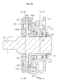
- FIG. 1 is a longitudinal sectional view of an overall structure of a clutch unit X according to an embodiment of the present invention.
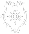
- FIG. 2 is a right-hand side view of the clutch unit X illustrated in FIG. 1 .
- FIG. 3 is a left-hand side view of the clutch unit X illustrated in FIG. 1 .
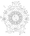
- FIG. 4 is a lateral sectional view taken along the line A-A of FIG. 1 .
- FIG. 5 is a lateral sectional view taken along the line B-B of FIG. 1 .
- FIGS. 6 to 18 illustrate main components of the clutch unit X.
- FIGS. 19 to 31 illustrate assembled states of the main components of the clutch unit X.
- the clutch unit X is incorporated into an automobile seat-lifter section (see FIGS. 32 , 33a, and 33b ) for adjusting a height of a seat through lever operation or the like. As illustrated in FIGS. 1 to 5 , the clutch unit X comprises a unit of a lever-side clutch portion 11 provided on an input side and a brake-side clutch portion 12 which is provided on an output side and which has a function of interrupting reverse input.
- the lever-side clutch portion 11 comprises a lever-side side plate 13 and a lever-side outer ring 14 each serving as an input-side member to which an operation lever (not shown) or the like is connected, an inner ring 15 serving as a coupling member which transmits torque from the lever-side outer ring 14 to the brake-side clutch portion 12, a plurality of cylindrical rollers 16 arranged as engagement elements in wedge gaps 20 formed between an outer peripheral surface 15a of the inner ring 15 and an inner peripheral surface 14a of the lever-side outer ring 14, a retainer 17 for retaining the cylindrical rollers 16 equiangularly, an inner centering spring 18 as a first elastic member for restoring the retainer 17 to a neutral state, and an outer centering spring 19 as a second elastic member for restoring the lever-side outer ring 14 to a neutral state.
- components are prevented from being detached by press-fitting a washer 31 onto an end portion of an output shaft 22 described later through intermediation of
- the so-called lock type brake-side clutch portion 12 which has a function of interrupting reverse input mainly comprises the inner ring 15 serving as a coupling member to which the torque from the lever-side clutch portion 11 is input, the output shaft 22 serving as an output-side member, a brake-side outer ring 23, a cover 24, and a brake-side side plate 25 each serving as a stationary-side member restricted in rotation, a plurality of pairs of cylindrical rollers 27 arranged as coupling members in wedge gaps 26 between the brake-side outer ring 23 and the output shaft 22, for controlling transmission of the torque input from the inner ring 15 and interruption of the torque reversely input from the output shaft 22 through engagement and disengagement betweenbothmembers, andplatesprings28of, for example, an N-shaped sectional configuration, each provided between the cylindrical rollers 27 of each pair and serving as elastic members for imparting repulsive force to the cylindrical rollers 27.
- protrusions 22f are provided to the output shaft 22 and inserted into
- FIGS. 6a and 6b illustrate the lever-side side plate 13 of the lever-side clutch portion 11.
- a hole 13a into which the output shaft 22 and the inner ring 15 are inserted is formed in a center portion thereof, and a plurality of (five, for example) claw portions 13b are provided in a protruding manner on an outer peripheral portion thereof.
- Those claw portions 13b are bent and molded in an axial direction so as to have bisected distal ends.
- the claw portions 13b are inserted into cutout recessed portions 14e (see FIG. 7c ) of the lever-side outer ring 14, which are described later.
- the distance between each of the bisected distal ends is increased outward.
- lever-side side plate 13 is fixed to the lever-side outer ring 14 by swaging.
- a plurality of (four, for example) holes for mounting the operation lever (not shown) for adjusting a height of a seat to the lever-side side plate 13 are represented by reference symbol 13c.
- FIGS. 7a to 7c illustrate the lever-side outer ring 14.
- the lever-side outer ring 14 is obtained by molding a plate-like material into a cup-shape through press working, and comprises a hole 14b formed in a center portion 14c, through which the output shaft 22 and the inner ring 15 are inserted.
- a plurality of cam surfaces 14a are equiangularly formed (see FIG. 4 ).
- a plurality of (three, for example) claw portions 14f and 14g are provided in a protruding manner and bent and molded in the axial direction.
- the one claw portion 14f is locked by being inserted and arranged between two lock portions 19a (see FIG. 12a ) of the outer centering spring 19 described later.
- the other two claw portions 14g slide on the end surface of the brake-side outer ring 23 in accordance with rotation of the lever-side outer ring 14, and move between a pair of lock portions 24e and 24f (see FIG.
- the plurality of (five in the figure) cutout recessed portions 14e into which the claw portions 13b (see FIGS. 6a and 6b ) of the lever-side side plate 13 are inserted are formed on an outer periphery of the lever-side outer ring 14.
- the lever-side outer ring 14 and the lever-side side plate 13 fixed by swaging to the lever-side outer ring 14 constitute the input-side member of the lever-side clutch portion 11.
- FIGS. 8a and 8b illustrate the inner ring 15.
- the inner ring 15 is provided with the outer peripheral surface 15a formed on an outer diameter of a cylindrical portion 15b into which the output shaft 22 is inserted, the wedge gaps 20 (see FIG. 4 ) being formed between the outer peripheral surface 15a and the cam surfaces 14a of the lever-side outer ring 14.
- a larger diameter portion 15c extending from an end portion of the cylindrical portion 15b in a radially outer direction and bending in the axial direction is integrally formed.
- pockets 15e for accommodating the cylindrical rollers 27 and the plate springs 28 are equiangularly formed in the larger diameter portion 15c.
- a plurality of holes into which the protrusions 22f of the output shaft 22 (see FIG. 1 ) are inserted with clearances are represented by a reference symbol 15d.
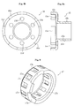
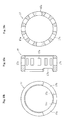
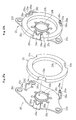
- FIGS. 9 , and 10a to 10e illustrate the retainer 17 made of a resin.
- the retainer 17 is a cylindrical member in which a plurality of pockets 17a for accommodating the cylindrical rollers 16 are equiangularly formed.
- Two cutout recessed portions 17b are formed in one end portion of the retainer 17, and lock portions 18a of the above-mentioned inner centering spring 18 are locked to adjacent two end surfaces 17c of the respective cutout recessed portions 17b (see FIG. 30 ).
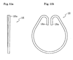
- FIGS. 11a and 11b illustrate the inner centering spring 18.
- the inner centering spring 18 is a spring member having a circular C-shape in cross-section and including a pair of the lock portions 18a bent to a radially inner side, and is situated on the radially inner side of the outer centering spring 19 (see FIG. 30 ) .
- the inner centering spring 18 is arranged between the retainer 17 and the cover 24 serving as a stationary-side member of the brake-side clutch portion 12.
- both the lock portions 18a are locked to the two end surfaces 17c (see FIGS. 9 and 10b ) of the retainer 17 and locked to a claw portion 24b (see FIGS. 16a and 16b ) provided to the cover 24 (see FIGS. 30 , 31a and 31b ).
- an interval m 1 between distal ends of the pair of lock portions 18a is set smaller than an interval m 2 between proximal ends of the pair of lock portions 18a (m 1 ⁇ m 2 ) under a state in which the inner centering spring 18 is assembled to the retainer 17, i.e., a state in which the pair of lock portions 18a are engaged with the end surfaces 17c of the retainer 17. That is, setting the interval m 1 between the distal ends of the pair of lock portions 18a of the inner centering spring 18 smaller than the interval m 2 between the proximal ends thereof means closing the pair of lock portions 18a to a radially inner side.
- the interval m 1 between the distal ends of the pair of lock portions 18a of the inner centering spring 18 is set smaller than the interval m 2 between the proximal ends thereof, and hence a force acting on the inner centering spring 18 is directed toward a center thereof by a reaction force acting on the pair of lock portions 18a. Accordingly, even when the inner centering spring 18, which accumulates an elastic force obtained by the torque input from the lever-side outer ring 14, is extended by rotating the lever-side outer ring 14 through lever operation, a force acting on the lock portions 18a of the inner centering spring 18 is directed to a radially inner side, and hence it is possible to prevent the lock portions 18a of the inner centering spring 18 from being disengaged from the end surfaces 17c of the retainer 17.
- a minute gap "c" is interposed between an inner diameter of the inner centering spring 18 and an outer diameter of the retainer 17.
- the minute gap "c” is interposed between the inner diameter of the inner centering spring 18 and the outer diameter of the retainer 17, and hence even if the radially outward force acts on the lock portion 18a of the inner centering spring 18 when the inner centering spring 18, which accumulates the elastic force obtained by the torque input from the lever-side outer ring 14, is extended at the time of lever operation, the inner diameter of the inner centering spring 18 is brought into abutment on the outer diameter of the retainer 17 so as to narrow the minute gap "c". Accordingly, it is possible to further reliably prevent the lock portions 18a of the inner centering spring 18 from being disengaged from the end surfaces 17c of the retainer 17.
- the inner diameter of the region 18b displaced by 180° from the pair of lock portions 18a is brought into abutment on the outer diameter of the retainer 17, and hence even if the radially outward force acts on the lock portion 18a of the inner centering spring 18 when the inner centering spring 18, which accumulates the elastic force obtained by the torque input from the lever-side outer ring 14, is extended at the time of lever operation, the inner diameter of the inner centering spring 18 is brought into abutment on the outer diameter of the retainer 17. Accordingly, it is possible to still further reliably prevent the lock portions 18a of the inner centering spring 18 from being disengaged from the end surfaces 17c of the retainer 17.
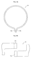
- FIGS. 12a and 12b illustrate the outer centering spring 19.
- the outer centering spring 19 is a band plate-like spring member having a C-shape and the pair of lock portions 19a formed by bending both the ends thereof to a radially outer side, and is situated on a radially outer side of the inner centering spring 18 (see FIG. 30 ).
- the outer centering spring 19 is arranged between the lever-side outer ring 14 of the lever-side clutch portion 11 and the cover 24 of the brake-side clutch portion 12. Both the lock portions 19a are locked to the claw portion 14f (see FIGS. 7a to 7c ) provided to the lever-side outer ring 14, and also locked to a claw portion 24d (see FIGS.
- the lock portions 19a are arranged while being displaced (by 180°) in a circumferential direction with respect to the lock portions 18a of the inner centering spring 18 (see FIG. 30 ).
- the outer centering spring 19 when the torque input from the lever-side side plate 13 is applied through lever operation so as to rotate the lever-side outer ring 14, one of the lock portions 19a is engaged with the claw portion 14f of the lever-side outer ring 14, and the other of the lock portions 19a is engaged with the claw portion 24d of the cover 24, respectively.
- the outer centering spring 19 is pressed and extended in accordance with the rotation of the lever-side outer ring 14 so as to accumulate an elastic force.
- the lever-side outer ring 14 is restored to a neutral state with the elastic restoring force.
- the outer centering spring 19 is provided between the cover 24 and the lever-side outer ring 14, and has such structure as to abut on the cover 24.
- the outer centering spring 19, which slides on the cover 24 climbs onto an inclined portion 24g of the cover 24 and thus comes into contact with the opposing lever-side outer ring 14.
- the outer centering spring 19 is set into the following form.
- the inner diameter of the outer centering spring 19 is arranged on an outer side of an outermost diameter of the inclined portion 24g of the cover 24.
- the outermost diameter of the inclinedportion 24g means a boundary portion 24k situated between the inclinedportion 24g and a bottom portion 24j extending outward from the inclined portion 24g of the cover 24.
- the inner diameter of the outer centering spring 19 is arranged on the outer side of the outermost diameter of the inclined portion 24g of the cover 24, and hence when operating the lever from a neutral position, the outer centering spring 19 is extended to the radially outer side. Accordingly, at the time of lever operation of restoring the lever from a full stroke to a neutral position, it is possible to prevent the outer centering spring 19, which slides on the cover 24, from climbing onto the inclined portion 24g of the cover 24, and it is possible to avoid contact of the outer centering spring 19 with the lever-side outer ring 14. Therefore, it is possible to prevent the occurrence of the noises.
- a distance "a" between an inner diameter of a region 19b displaced by 180° from the pair of lock portions 19a and the outermost diameter (boundary portion 24k) of the inclined portion 24g of the cover 24 is set larger than a distance "b" between an inner diameter of a region 19c displaced by 90° from the pair of lock portions 19a and the outermost diameter (boundary portion 24k) of the inclined portion 24g of the cover 24 (a>b).
- the distances "a” and “b” are set in this manner, and hence even at the region 19b at which the outer centering spring 19 is moved by a relatively small amount at the time of lever operation, the distance can be reliably ensured. Accordingly, at the time of lever operation, it is possible to reliably prevent the outer centering spring 19, which slides on the cover 24, from climbing onto the inclined portion 24g of the cover 24.
- an interval n 1 between distal ends of the pair of lock portions 19a of the outer centering spring 19 is set larger than an interval n 2 between proximal ends of the pair of lock portions 19a (n 1 >n 2 ). That is, setting the interval n 1 between the distal ends of the pair of lock portions 19a of the outer centering spring 19 larger than the interval n 2 between the proximal ends thereof means extending the pair of lock portions 19a outward. Note that, it is preferred that an extension angle ⁇ of the pair of lock portions 19a be about 20°.
- the interval n 1 between the distal ends of the pair of lock portions 19a of the outer centering spring 19 is set larger than the interval n 2 between the proximal ends thereof, and hence a force acting on the outer centering spring 19 is directed toward the center thereof by a reaction force acting on the pair of lock portions 19a. Accordingly, at the time of lever operation, it is possible to further reliably prevent the outer centering spring 19, which slides on the cover 24, from climbing onto the inclined portion 24g of the cover 24.
- an inclined portion 24g' of the cover 24 is formed into a cylindrical shape.
- the inclined portion 24g' of the cover 24 is formed into a cylindrical shape, and hence the inclined portion 24g' having a cylindrical shape forms a step. Accordingly, it is possible to further reliably prevent the outer centering spring 19, which is situated on the outer side of the inclined portion 24g of the cover 24, from climbing onto the inclined portion 24g.
- FIGS. 13a and 13b and FIGS. 14a to 14c illustrate the output shaft 22.
- the output shaft 22 comprises a larger diameter portion 22d which extends from a shaft portion 22c to the radially outer side to be increased in diameter, and is integrally formed substantially in an axial center region of the output shaft 22.
- Apinion gear 41g to be coupled to a seat-lifter section 41 is coaxially formed on a distal end of the shaft portion 22c.
- a plurality of (six, for example) flat cam surfaces 22a are equiangularly formed on an outer peripheral surface of the larger diameter portion 22d, and the two cylindrical rollers 27 and the plate spring 28 are arranged in each wedge gap 26 (see FIG. 5 ) provided between the cam surfaces 22a and an inner peripheral surface 23b of the brake-side outer ring 23.
- an annular recessed portion 22b in which a friction ring 29 is accommodated and arranged.
- protrusions formed on the other end surface of the larger diameter portion 22d are represented by reference symbol 22f, the protrusions being inserted into the holes 15d of the inner ring 15 with clearances (see FIGS. 1 , 8a, and 8b ).
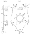
- FIGS. 15a and 15b illustrate the brake-side outer ring 23, and FIGS. 16a and 16b illustrate the cover 24.
- FIGS. 17a and 17b illustrate the brake-side side plate 25.
- the brake-side outer ring 23 and the cover 24 described above are integrally fixed to each other with the brake-side side plate 25 by swaging.
- the brake-side outer ring 23 is formed of a thick plate-like member obtained by punching of a single material with a press, and the cover 24 is molded by pressing of another single material.
- the cover 24 has the inclined portion 24g, which extends to the radially outer side in a state of abutting on the larger diameter portion 15c of the inner ring 15 described above (see FIG. 1 ).
- holes into which the output shaft 22 is inserted are represented by reference symbols 24c and 25b, and holes with which protrusions 29a of the friction ring 29 described later are fitted are represented by reference symbol 25c.
- a plurality of (three) cutout recessed portions 23a are formed on an outer periphery of the brake-side outer ring 23.
- a plurality of (three) cutout recessed portions 24a are similarly formed on an outer periphery of the cover 24.
- claw portions 25a of the brake-side side plate 25 are inserted into the cutout recessed portions 23a of the brake-side outer ring 23, respectively.
- the claw portions 25a of the brake-side side plate 25 are inserted into the cutout recessed portions 24a of the cover 24, respectively.
- the claw portions 25a of the brake-side side plate 25 are inserted into the cutout recessed portions 23a and 24a.
- the brake-side outer ring 23 and the cover 24 are coupled to each other and integrated with the brake-side side plate 25. Swaging of the claw portions 25a of the brake-side side plate 25 is performed by increasing outward the distance between bisected distal end portions 25a 1 of each of the claw portions 25a with use of a swage (not shown) (see FIG. 29 ).
- the wedge gaps 26 are formed between the inner peripheral surface 23b of the brake-side outer ring 23 and the cam surfaces 22a of the output shaft 22 (see FIG. 5 ).
- the cover 24 is provided with the claw portion 24b protruding in the axial direction, the claw portion 24b being arranged between the two lock portions 18a of the inner centering spring 18 of the lever-side clutch portion 11 (see FIGS. 11b 31a, and 31b ).
- the claw portion 24b of the cover 24 is formed by raising the surface of the cover 24 on the radially outer side of the claw-portion-formation position.
- the claw portion 24d protruding in the axial direction is formed on the outer periphery of the cover 24.
- the claw portion 24d is arranged between the two lock portions 19a of the outer centering spring 19 of the lever-side clutch portion 11 (see FIGS. 12a , 31a and 31b ).
- Two pairs of the lock portions 24e and 24f are formed by stepping on the outer periphery of the cover 24 (see FIGS. 31a and 31b ).
- the lock portions 24e and 24f are allowed to be brought into abutment, in a rotational direction, on the claw portions 14g, which slide on the end surface of the brake-side outer ring 23.
- the lock portions 24e and 24f function as rotation stoppers for restricting an operating angle of the operation lever.
- the claw portions 14g thereof move along the outer periphery of the cover 24 between the lock portions 24e and 24f of the cover 24.
- one flange portion 25e and two flange portions 25f are provided as clutch mounting portions with respect to the seat-lifter section (see FIGS. 2 to 4 ).
- distal end portions of those three flange portions 25e and 25f there are formed, by boring, mounting holes 25g and 25h for allowing mounting with respect to the seat-lifter section, and there are protrudingly formed, in the axial direction, cylindrical portions 25i and 25j in a manner of surrounding the mounting holes 25g and 25h.
- FIGS. 18a to 18c illustrate the friction ring 29 made of a resin.
- the plurality of circular protrusions 29a are equiangularly formed.
- the friction ring 29 is fixed to the brake-side side plate 25 (see FIGS. 1 and 3 ).
- the friction ring 29 is press-fitted to an inner peripheral surface 22e of the annular recessed portion 22b formed in the larger diameter portion 22d of the output shaft 22 with fastening allowance (see FIGS. 13a , 14a and 14b ). Due to a frictional force generated between an outer peripheral surface 29c of the friction ring 29 and the inner peripheral surface 22e of the annular recessed portion 22b of the output shaft 22, rotational resistance is imparted to the output shaft 22.
- the slits 29b serve as grease pools, and hence it is possible to suppress abrasion of the outer peripheral surface 29c of the friction ring 29 due to sliding with respect to the inner peripheral surface 22e of the annular recessed portion 22b of the output shaft 22.
- the friction ring 29 is made of a material capable of keeping a fastening allowance between the output shaft 22 and the friction ring 29. It is preferred that polybutylene terephthalate (PBT) be used as the material. Thus, the friction ring 29 is made of polybutylene terephthalate, and hence reduction in fastening allowance of the friction ring 29 over time can be easily suppressed. As a result, even if excessive torque is applied to the output shaft 22, when a locked state of the brake-side clutch portion 12 is released through lever operation performed at the lever-side clutch portion 11, predetermined rotational resistance can be imparted to the output shaft 22. Accordingly, it is possible to prevent occurrence of strong vibration caused by an increase in contact pressure of the cylindrical rollers 27. Note that, as the material for the friction ring, materials other than the above-mentioned polybutylene terephthalate may be used as long as the materials can keep the fastening allowance between the output shaft 22 and the friction ring.
- An inner peripheral surface 29d of the friction ring 29 is formed into a circular shape concentric with the outer peripheral surface 29c of the friction ring 29 (see FIGS. 5 , 18b, and 18c ).
- the inner peripheral surface 29d of the friction ring 29 is formed into a circular shape, and hence rigidity of the friction ring 29 can be increased as compared to rigidity of the conventional friction ring 129 (see FIG. 36 ). Accordingly, it is possible to increase durability of the entire clutch unit.
- the friction ring 29 is press-fitted to the inner peripheral surface 22e of the annular recessed portion 22b formed in the larger diameter portion 22d of the output shaft 22 with a fastening allowance, the friction ring 29 is made of a resin, and hence burrs may occur on the outer peripheral surface 29c of the friction ring 29 at the time of the press-fitting.
- a chamfer angle ⁇ of a chamfered portion 22g is set to 20° to 25°, the chamfered portion 22g being formed on a peripheral edge portion of the annular recessed portion 22b of the output shaft 22.
- a range of the chamfer angle ⁇ is determined, and hence when the friction ring 29 is press-fitted to the annular recessed portion 22b of the output shaft 22, it is possible to smoothly press-fit the friction ring 29 to the annular recessed portion 22b, and to prevent the occurrence of burrs.
- the chamfer angle ⁇ is smaller than 20°, burrs are more likely to occur.
- the chamfer angle ⁇ is larger than 25°, press-fitting load is increased, which leads to a difficulty in press-fitting.
- the friction ring 29 made of a resin is manufactured using molding dies 50, as illustrated in FIG. 26 , one die 50a and another die 50b are split at a position at which a bottom of the protrusion 29a is to be molded.
- the friction ring 29 is manufactured using the molding dies 50 described above, and hence a part of the friction ring 29, which is to be press-fitted to the annular recessed portion 22b of the output shaft 22, is molded in only the another die 50b. Accordingly, burrs are less likely to occur at the time of press-fitting.
- the cylindrical rollers 27 are engaged into the wedge gaps 26 between the output shaft 22 and the brake-side outer ring 23 so as to lock the output shaft 22 with respect to the brake-side outer ring 23. Accordingly, the torque reversely input from the output shaft 22 is locked by the brake-side clutch portion 12 so as to interrupt back-flow of the torque to be reverse-input to the lever-side clutch portion 11.
- the torque input from the lever-side outer ring 14 is input to the inner ring 15 through the intermediation of the lever-side clutch portion 11.
- the inner ring 15 is brought into abutment on the cylindrical rollers 27 and presses the cylindrical rollers 27 against the elastic force of the plate springs 28, the cylindrical rollers 27 are disengaged from the wedge gaps 26 and a locked state of the output shaft 22 is released.
- the output shaft 22 is allowed to be rotated.
- the inner ring 15 is further rotated, clearances between the holes 15d of the inner ring 15 and the protrusions 22f of the output shaft 22 are narrowed, and the inner ring 15 is brought into abutment on the protrusions 22f of the output shaft 22 in a rotational direction.
- the torque input from the inner ring 15 is transmitted to the output shaft 22 through the intermediation of the protrusions 22f, and the output shaft 22 is rotated.
- FIG. 32 illustrates a seat 40 installed in a cabin of an automobile.
- the seat 40 comprises a sitting seat 40a, a backrest seat 40b, and the seat-lifter section 41 for adjusting a height H of the sitting seat 40a. Adjustment of the height H of the sitting seat 40a is performed with an operation, lever 41a of the seat-lifter section 41.
- FIG. 33a is a conceptual view of a structural example of the seat-lifter section 41.
- One ends of link members 41c and 41d are pivotally mounted to a slide movable member 41b 1 of a seat slide adjuster 41b.
- the other ends of the link members 41c and 41d are pivotally mounted to the sitting seat 40a.
- the other end of the link member 41c is pivotally mounted to a sector gear 41f through intermediation of a link member 41e.
- the sector gear 41f is pivotally mounted to the sitting seat 40a, and pivotable about a fulcrum 41f 1 .
- the other end of the link member 41d is pivotally mounted to the sitting seat 40a.
- the clutch unit X described above in this embodiment is fixed to an appropriate position of the sitting seat 40a. Fixation of the clutch unit X to the sitting seat 40a is fixation by swaging to a seat frame (not shown) of the sitting seat 40a, in which the three flange portions 25e and 25f of the brake-side side plate 25 are subjected to plastic deformation in a manner that the distal end portions of the cylindrical portions 25i and 25j are increased in diameter outward.
- the operation lever 41a made of, for example, a resin is coupled to the lever-side side plate 13 of the lever-side clutch portion 11, and the pinion gear 41g meshing with the sector gear 41f as a rotary member is provided to the output shaft 22 of the brake-side clutch portion 12.
- the pinion gear 41g is integrally formed at a distal end portion of the shaft portion 22c of the output shaft 22.
Landscapes
- Engineering & Computer Science (AREA)
- Mechanical Engineering (AREA)
- General Engineering & Computer Science (AREA)
- Aviation & Aerospace Engineering (AREA)
- Transportation (AREA)
- Braking Arrangements (AREA)
- Mechanical Operated Clutches (AREA)
Abstract
Description
- The present invention relates to a clutch unit having a lever-side clutch portion for transmitting rotational torque from an input side to an output side thereof and a brake-side clutch portion for transmitting rotational torque from the input side to the output side and interrupting torque reversely input from the output side.
- In general, in a clutch unit using engagement elements such as cylindrical rollers or balls, a clutch portion is arranged between an input-side member and an output-side member. Further, in the clutch portion, the engagement elements such as cylindrical rollers or balls are engaged and disengaged with respect to wedge gaps formed between the input-side member and the output-side member, thereby controlling transmission and interruption of the input torque.
- The applicant of the present invention has previously proposed a clutch unit incorporated into, for example, an automobile seat-lifter section which vertically adjusts a seat through lever operation. This clutch unit is provided with a lever-side clutch portion for transmitting rotational torque from the input side to the output side and a brake-side clutch portion for transmitting rotational torque from the input side to the output side and interrupting torque reversely input from the output side (see, for example, Patent Literature 1).
-
FIG. 34 is a longitudinal sectional view of an overall structure of the conventional clutch unit disclosed in Patent Literature 1,FIG. 35 is a sectional view taken along the line D-D ofFIG. 34 , andFIG. 36 is a sectional view taken along the line E-E ofFIG. 34 . - As illustrated in
FIGS. 34 and35 , a lever-side clutch portion 111 mainly includes a lever-sideouter ring 114 serving as an input-side member to which torque is input through lever operation, aninner ring 115 serving as a coupling member for transmitting the torque from the lever-sideouter ring 114 to a brake-side clutch portion 112, a plurality ofcylindrical rollers 116 serving as engagement elements for controlling transmission and interruption of the torque input from the lever-sideouter ring 114 through engagement and disengagement between the lever-sideouter ring 114 and theinner ring 115, aretainer 117 for retaining thecylindrical rollers 116 at predetermined circumferential intervals, a brake-sideouter ring 123 serving as a stationary-side member restricted in rotation, aninner centering spring 118 serving as a first elastic member which is provided between theretainer 117 and the brake-sideouter ring 123, for accumulating an elastic force obtained by the torque input from the lever-sideouter ring 114 and restoring theretainer 117 to a neutral state with the accumulated elastic force through releasing of the input torque, and anouter centering spring 119 serving as a second elastic member which is provided between the lever-sideouter ring 114 and the brake-sideouter ring 123, for accumulating an elastic force obtained by the torque input from the lever-sideouter ring 114 and restoring the lever-sideouter ring 114 to the neutral state with the accumulated elastic force through releasing of the input torque. - Note that, in the figures,
reference numeral 113 represents a lever-side side plate fixed to the lever-sideouter ring 114 by swaging and constituting the input-side member together with the lever-sideouter ring 114, andreference numeral 131 represents a washer mounted to anoutput shaft 122 through the intermediation of awave washer 130. - Meanwhile, as illustrated in
FIGS. 34 and36 , the brake-side clutch portion 112 mainly includes the brake-sideouter ring 123 serving as a stationary-side member restricted in rotation, theinner ring 115 serving as a coupling member to which torque from the lever-side clutch portion 111 is input, and a plurality of pairs ofcylindrical rollers 127 serving as engagement elements arranged in wedge gaps between the brake-sideouter ring 123 and theoutput shaft 122, for controlling transmission of torque input from theinner ring 115 and interruption of torque reversely input from theoutput shaft 122 through engagement and disengagement between the brake-sideouter ring 123 and theoutput shaft 122. - A
larger diameter portion 115c extending from an axial end portion of theinner ring 115 in a radially outer direction and bending in an axial direction functions as a retainer for retaining thecylindrical rollers 127 at predetermined circumferential intervals. In the figures,reference numerals outer ring 123, and the brake-sideouter ring 123 and thecover 124 are integrally fixed to each other with the brake-side side plate 125 by swaging .Reference numeral 128 represents a plate spring of, for example, an N-shaped sectional configuration arranged between thecylindrical rollers 127 of each pair, andreference numeral 129 represents a friction ring serving as a braking member mounted to the brake-side side plate 125. - [PTL1]
JP 2009-210114 A - By the way, the conventional clutch unit disclosed in Patent Literature 1 has the following structure. Specifically, the stationary-side member includes the brake-side
outer ring 123, thecover 124, and the brake-side side plate 125, and the brake-sideouter ring 123 and thecover 124 are integrally fixed to each other with the brake-side side plate 125 by swaging. The conventional clutch unit also has the following structure. Specifically, when the lever-sideouter ring 114 is rotated through lever operation, theouter centering spring 119 accumulates an elastic force obtained by torque input from the lever-sideouter ring 114, and restores the lever-sideouter ring 114 to a neutral state with the accummulated elastic force through releasing of the input torque. Theouter centering spring 119 is provided between the lever-sideouter ring 114 and thecover 124 constituting the stationary-side member together with the brake-sideouter ring 123. Theouter centering spring 119 is held in abutment on thecover 124. - In a case of the clutch unit having the above-mentioned structure, at the time of lever operation of restoring a lever from a full stroke to a neutral position, the
outer centering spring 119, which slides on thecover 124, may climb onto aninclined portion 124g of the cover 124 (seeFIG. 34 ) and thus come into contact with the opposing lever-sideouter ring 114. When theouter centering spring 119 climbs in this manner by sliding, the outer centeringspring 119 comes into contact with the lever-sideouter ring 114, with the result that slight noises occur. The noises bring a feeling of discomfort to a passenger who adjusts a seat vertically through lever operation. - Further, the conventional clutch unit has the following structure. Specifically, when the lever-side
outer ring 114 is rotated through lever operation, theinner centering spring 118 accumulates an elastic force obtained by the input torque from the lever-sideouter ring 114, and restores theretainer 117 to a neutral state with the accummulated elastic force through releasing of the input torque. Theinner centering spring 118 is provided between theretainer 117 and thecover 124 constituting the stationary-side member together with the brake-sideouter ring 123. Theinner centering spring 118 is held in abutment on thecover 124. - In a case of the clutch unit having the above-mentioned structure, when the lever-side
outer ring 114 is rotated through lever operation, theinner centering spring 118 for accumulating the elastic force obtained by the torque input from the lever-sideouter ring 114 is extended, with the result that a radially outward force acting at the time of extension may disengage theinner centering spring 118 from theretainer 117. - Further, in the conventional clutch unit, the
friction ring 129, which serves as a braking member fitted onto the brake-side side plate 125, is press-fitted to an annular recessed portion 122b of theoutput shaft 122 with a fastening allowance. Due to a frictional force generated between an inner peripheral surface 122e of the annular recessed portion 122b of theoutput shaft 122 and thefriction ring 129 with the fastening allowance, rotational resistance is imparted to the output shaft 122 (seeFIGS. 34 and36 ). - However, when a material forming the
friction ring 129 is degraded over time, it is difficult to keep the fastening allowance between theoutput shaft 122 and thefriction ring 129. As a result, when excessive torque is applied to theoutput shaft 122, at the time of releasing a locked state of the brake-side clutch portion 112 through lever operation performed at the lever-side clutch portion 111, it is difficult for thefriction ring 129 to impart predetermined rotational resistance to theoutput shaft 122 because of reduction in fastening allowance between theoutput shaft 122 and thefriction ring 129. Accordingly, contact pressure of thecylindrical rollers 127 may be increased to cause occurrence of strong vibration. The vibration brings a feeling of discomfort to a passenger who adjusts a seat vertically through lever operation. - Therefore, the present invention has been proposed in view of the above-mentioned problems, and has an object to provide the following clutch unit. Specifically, the clutch unit is capable of forestalling occurrence of noises caused by contact of the outer centering spring with the lever-side outer ring at the time of lever operation, and forestalling disengagement of the inner centering spring from the retainer. In addition, the clutch unit is capable of suppressing reduction in fastening allowance of the friction ring over time.
- A clutch unit according to the present invention comprises: a lever-side clutch portion provided on an input side, for controlling transmission and interruption of rotational torque to an output side through lever operation; and a brake-side clutch portion provided on the output side, for transmitting torque input from the lever-side clutch portion to the output side and for interrupting torque reversely input from the output side.
- The lever-side clutch portion according to the present invention comprises: an input-side member to be rotated through the lever operation; a stationary-side member restricted in rotation; and an elastic member provided between the input-side member and the stationary-side member, for accumulating an elastic force obtained by torque input from the input-side member and for restoring the input-side member to a neutral state with the accumulated elastic force through releasing of the torque input from the input-side member.
- In the clutch unit according to the present invention, the elastic member comprises a band plate-like spring member having a C-shape, the stationary-side member comprises an inclined portion which abuts on the elastic member and swells to the elastic member side, and under a state in which the elastic member is assembled, an inner diameter of the elastic member is arranged on an outer side of an outermost diameter of the inclined portion of the stationary-side member.
- According to the present invention, under the state in which the elastic member is assembled, the inner diameter of the elastic member is arranged on the outer side of the outermost diameter of the inclined portion of the stationary-side member. Thus, at the time of lever operation of restoring a lever from a full stroke to a neutral position, it is possible to prevent the elastic member, which slides on the stationary-side member, from climbing onto the inclined portion of the stationary-side member, and to avoid contact of the elastic member with the input-side member. Accordingly, it is possible to prevent occurrence of noises.
- According to the present invention, it is desired that the elastic member comprise a pair of lock portions formed by bending both ends thereof to a radially outer side, and under the state in which the elastic member is assembled, a distance between an inner diameter of a region of the elastic member, which is displaced by 180° from the pair of lock portions and the outermost diameter of the inclined portion of the stationary-side member be set larger than a distance between an inner diameter of a region of the elastic member, which is displaced by 90° from the pair of lock portions and the outermost diameter of the inclined portion of the stationary-side member. With this, at the time of lever operation, it is possible to reliably prevent the elastic member, which slides on the stationary-side member, from climbing onto the inclined portion of the stationary-side member.
- According to the present invention, it is desired that, under the state in which the elastic member is assembled, an interval between distal ends of the pair of lock portions of the elastic member be set larger than an interval between proximal ends of the pair of lock portions of the elastic member. With this, a force acting on the elastic member is directed toward a center thereof by a reaction force acting on the pair of lock portions. Accordingly, at the time of lever operation, it is possible to further reliably prevent the elastic member, which slides on the stationary-side member, from climbing onto the inclined portion of the stationary-side member.
- According to the present invention, it is desired that the inclined portion of the stationary-side member be formed into a cylindrical shape. With this, it is possible to further reliably prevent the elastic member, which is situated on the outer side of the inclined portion, from climbing onto the inclined portion.
- Further, in the clutch unit according to the present invention, the elastic member comprises a C-shaped spring member which comprises a pair of lock portions formed by bending both ends thereof to a radially inner side, and under a state in which the elastic member is assembled, an interval between distal ends of the pair of lock portions of the elastic member is set smaller than an interval between proximal ends thereof.
- According to the present invention, under the state in which the elastic member is assembled, the interval between the distal ends of the pair of lock portions of the elastic member is set smaller than the interval between the proximal ends thereof. Accordingly, even when the elastic member, which accumulates an elastic force obtained by torque input from the input-side member, is extended by rotating the input-side member through lever operation, a force acting on the lock portions of the elastic member is directed to a radially inner side, and hence it is possible to prevent the lock portions of the elastic member from being disengaged from the retainer.
- According to the present invention, it is desired that under the state in which the elastic member is assembled, a minute gap be interposed between an inner diameter of the elastic member and an outer diameter of the retainer. With this, even if a radially outward force acts on the lock portions of the elastic member when the elastic member, which accumulates the elastic force obtained by the torque input from the input-side member, is extended at the time of lever operation, the inner diameter of the elastic member is brought into abutment on the outer diameter of the retainer so as to narrow the minute gap. Accordingly, it is possible to further reliably prevent the lock portions of the elastic member from being disengaged from the retainer.
- According to the present invention, it is desired that under the state in which the elastic member is assembled, an inner diameter of a region of the elastic member, which is displaced by 180° from the pair of lock portions, be brought into abutment on the outer diameter of the retainer. With this, even if the radially outward force acts on the lock portions of the elastic member when the elastic member, which accumulates the elastic force obtained by the torque input from the input-side member, is extended at the time of lever operation, the inner diameter of the elastic member is brought into abutment on the outer diameter of the retainer. Accordingly, it is possible to still further reliably prevent the lock portions of the elastic member from being disengaged from the retainer.
- In addition, in the clutch unit according to the present invention, the friction ring is made of a material capable of keeping a fastening allowance between the output-side member and the friction ring. As the material for the friction ring, polybutylene terephthalate (PBT) is preferred.
- According to the present invention, the friction ring is made of a material, for example, polybutylene terephthalate, capable of keeping a fastening allowance between the output-side member and the friction ring, and hence reduction in fastening allowance of the friction ring over time can be easily suppressed. As a result, even when excessive torque is applied to the output-side member, at the time of releasing a locked state of the brake-side clutch portion through lever operation performed at the lever-side clutch portion, predetermined rotational resistance can be imparted to the output-side member. Accordingly, it is possible to prevent occurrence of strong vibration caused by an increase in contact pressure of the cylindrical rollers.
- According to the present invenetion, it is desired that the friction ring have an inner diameter formed into a circular shape. With this, it is possible to increase rigidity of the friction ring, and to increase durability of the entire clutch unit.
- According to the present invention, it is desired that the friction ring be press-fitted to an annular recessed portion formed in the output-side member, and the annular recessed portion comprise a chamfered portion formed on a peripheral edge portion thereof, the chamfered portion having a chamfer angle of 20° to 25° . With this, when the friction ring is press-fitted to the annular recessedportion of the output-side member, it is possible to smoothly press-fit the friction ring to the annular recessed portion, and to prevent occurrence of burrs.
- The lever-side clutch portion in the clutch unit may comprise: an input-side member to which torque is input through the lever operation; a coupling member for transmitting the torque input from the input-side member to the brake-side clutch portion; a plurality of engagement elements for controlling transmission and interruption of the torque input from the input-side member through engagement and disengagement between the input-side member and the coupling member; a retainer for retaining the plurality of engagement elements at predetermined intervals in a circumferential direction; a stationary-side member restricted in rotation; a first elastic member provided between the retainer and the stationary-side member, for accumulating an elastic force obtained by the torque input from the input-side member and for restoring the retainer to a neutral state with the accumulated elastic force through releasing of the torque input from the input-side member; and a second elastic member provided between the input-side member and the stationary-side member, for accumulating an elastic force by the torque input from the input-side member and for restoring the input-side member to a neutral state with the accumulated elastic force through releasing of the torque input from the input-side member. It is desired that cylindrical rollers be used for the engagement elements of the lever-side clutch portion.
- The brake-side clutch portion in the clutch unit may comprise: a coupling member to which torque is input from the lever-side clutch portion; an output-side member from which the torque is output; a stationary-side member restricted in rotation; and a plurality of pairs of engagement elements arranged in wedge gaps between the stationary-side member and the output-side member, for controlling transmission of the torque input from the coupling member and interruption of the torque reversely input from the output-side member through engagement and disengagement between the stationary-side member and the output-side member. It is desired that cylindrical rollers be used for the engagement elements of the brake-side clutch portion.
- In the clutch unit according to the present invention, the lever-side clutch portion and the brake-side clutch portion are incorporated in an automobile seat-lifter section. Thus, the clutch unit is suited for use in an automobile. In this case, the clutch unit has a configuration in which the input-side member is connected to an operation lever and the output-side member is coupled to a link mechanism of the automobile seat-lifter section.
- According to the present invention, under the state in which the elastic member is assembled, the inner diameter of the elastic member is arranged on the outer side of the outermost diameter of the inclined portion of the stationary-side member. Thus, at the time of lever operation of restoring the lever from a full stroke to a neutral position, it is possible to prevent the elastic member, which slides on the stationary-side member, from climbing onto the inclined portion of the stationary-side member, and to avoid contact of the elastic member with the input-side member. Accordingly, it is possible to prevent the occurrence of noises. As a result, in a case where the clutch unit is incorporated into the automobile seat-lifter section, lever operation of adjusting a seat vertically is performed satisfactorily, and hence comfortable lever operation can be realized.
- According to the present invention, under the state in which the elastic member is assembled, the interval between the distal ends of the pair of lock portions of the elastic member is set smaller than the interval between the proximal ends thereof. Accordingly, even when the elastic member, which accumulates an elastic force obtained by torque input from the input-side member, is extended by rotating the input-side member through lever operation, a force acting on the lock portions of the elastic member is directed to a radially inner side, and hence it is possible to prevent the lock portions of the elastic member from being disengaged from the retainer. Therefore, it is possible to provide a clutch unit with a long life and high reliability.
- Further, according to the present invention, the friction ring is made of a material, for example, polybutylene terephthalate, capable of keeping the fastening allowance between the output-side member and the friction ring, and hence reduction in fastening allowance of the friction ring over time can be easily suppressed. As a result, even when excessive torque is applied to the output-side member, at the time of releasing a locked state of the brake-side clutch portion through lever operation performed at the lever-side clutch portion, predetermined rotational-resistance can be imparted to the output-side member. Accordingly, it is possible to prevent occurrence of strong vibration caused by the increase in contact pressure of the cylindrical rollers. As a result, in a case where the clutch unit is incorporated into the automobile seat-lifter section, lever operation of adjusting a seat vertically is performed satisfactorily, and hence comfortable lever operation can be realized.
-
- [
FIG. 1 ] A longitudinal sectional view of an overall structure of a clutch unit according to an embodiment of the present invention. - [
FIG. 2 ] A right-hand side view ofFIG. 1 . - [
FIG. 3 ] A left-hand side view ofFIG. 1 . - [
FIG. 4 ] A sectional view taken along the line A-A ofFIG. 1 . - [
FIG. 5 ] A sectional view taken along the line B-B ofFIG. 1 . - [
FIG. 6a ] A sectional view of a lever-side side plate. - [
FIG. 6b ] A left-hand side view ofFIG. 6a . - [
FIG. 7a ] A sectional view illustrating an example of a lever-side outer ring. - [
FIG. 7b ] A left-hand side view ofFIG. 7a . - [
FIG. 7c ] A right-hand side view ofFIG. 7a . - [
FIG. 8a ] A sectional view of an inner ring. - [
FIG. 8b ] A left-hand side view ofFIG. 8a . - [
FIG. 9 ] A perspective view of a retainer. - [
FIG. 10a ] A sectional view of the retainer. - [
FIG. 10b ] A left-hand side view ofFIG. 10a . - [
FIG. 10c ] A sectional view ofFIG. 10a . - [
FIG. 11a ] A front view of an inner centering spring. - [
FIG. 11b ] A right-hand side view ofFIG. 11a . - [
FIG. 12a ] A side view of an outer centering spring. - [
FIG. 12b ] A partially enlarged bottom view ofFIG. 12a . - [
FIG. 13a ] A perspective view of an output shaft seen from one side. - [
FIG. 13b ] A perspective view of the output shaft seen from another side. - [
FIG. 14a ] A sectional view of the output shaft. - [
FIG. 14b ] A left-hand side view ofFIG. 14a . - [
FIG. 14c ] A right-hand side view ofFIG. 14a . - [
FIG. 15a ] A sectional view of a brake-side outer ring. - [
FIG. 15b ] A left-hand side view ofFIG. 15a . - [
FIG. 16a ] A sectional view of a cover. - [
FIG. 16b ] A left-hand side view ofFIG. 16a . - [
FIG. 17a ] A sectional view of a brake-side side plate. - [
FIG. 17b ] A right-hand side view ofFIG. 17a . - [
FIG. 18a ] A front view of a friction ring. - [
FIG. 18b ] A left-hand side view ofFIG. 18a . - [
FIG. 18c ] A right-hand side view ofFIG. 18a . - [
FIG. 19 ] A side view illustrating an example in which the inner centering spring is assembled to the retainer. - [
FIG. 20 ] A side view illustrating another example in which the inner centering spring is assembled to the retainer. - [
FIG. 21 ] A side view illustrating the outer centering spring and the cover. - [
FIG. 22 ] A partially enlarged sectional view illustrating the cover. - [
FIG. 23 ] A partially enlarged side view illustrating the outer centering spring and a claw portion of the cover. - [
FIG. 24 ] A partially enlarged sectional view illustrating an embodiment in which an inclined portion of the cover is formed into a cylindrical shape. - [
FIG. 25 ] A partially enlarged sectional view illustrating a state before the friction ring is assembled to the output shaft by press-fitting. - [
FIG. 26 ] A sectional view illustrating molding dies for manufacturing the friction ring. - [
FIG. 27a ] A perspective view illustrating a state before the brake-side outer ring is assembled to the brake-side side plate. - [
FIG. 27b ] A perspective view illustrating a state after the brake-side outer ring is assembled to the brake-side side plate. - [
FIG. 28 ] A perspective view illustrating a state in which the brake-side outer ring and the cover are assembled to the brake-side side plate. - [
FIG. 29 ] A perspective view illustrating a state in which the brake-side side plate, the brake-side outer ring, and the cover are integrated with one another by swaging. - [
FIG. 30 ] A sectional view taken along the line C-C ofFIG. 1 . - [
FIG. 31a ] A perspective view illustrating a state before the retainer is assembled to the brake-side side plate, the brake-side outer ring, the cover, and the inner centering spring. - [
FIG. 31b ] A perspective view illustrating a state after the retainer is assembled to the brake-side side plate, the brake-side outer ring, the cover, and the inner centering spring. - [
FIG. 32 ] A conceptual view of a seat of an automobile. - [
FIG. 33a ] A conceptual view of a structural example of a seat-lifter section. - [
FIG. 33b ] An enlarged view of a main part ofFIG. 33a . - [
FIG. 34 ] A longitudinal sectional view of an overall structure of a conventional clutch unit. - [
FIG. 35 ] A lateral sectional view taken along the line D-D ofFIG. 34 . - [
FIG. 36 ] A lateral sectional view taken along the line E-E ofFIG. 34 . -
FIG. 1 is a longitudinal sectional view of an overall structure of a clutch unit X according to an embodiment of the present invention.FIG. 2 is a right-hand side view of the clutch unit X illustrated inFIG. 1 .FIG. 3 is a left-hand side view of the clutch unit X illustrated inFIG. 1 .FIG. 4 is a lateral sectional view taken along the line A-A ofFIG. 1 .FIG. 5 is a lateral sectional view taken along the line B-B ofFIG. 1 . Further,FIGS. 6 to 18 illustrate main components of the clutch unit X.FIGS. 19 to 31 illustrate assembled states of the main components of the clutch unit X. - The clutch unit X is incorporated into an automobile seat-lifter section (see
FIGS. 32 ,33a, and 33b ) for adjusting a height of a seat through lever operation or the like. As illustrated inFIGS. 1 to 5 , the clutch unit X comprises a unit of a lever-sideclutch portion 11 provided on an input side and a brake-sideclutch portion 12 which is provided on an output side and which has a function of interrupting reverse input. - As illustrated in
FIGS. 1 ,2 , and4 , the lever-sideclutch portion 11 comprises a lever-side side plate 13 and a lever-sideouter ring 14 each serving as an input-side member to which an operation lever (not shown) or the like is connected, aninner ring 15 serving as a coupling member which transmits torque from the lever-sideouter ring 14 to the brake-sideclutch portion 12, a plurality ofcylindrical rollers 16 arranged as engagement elements inwedge gaps 20 formed between an outerperipheral surface 15a of theinner ring 15 and an innerperipheral surface 14a of the lever-sideouter ring 14, aretainer 17 for retaining thecylindrical rollers 16 equiangularly, an inner centeringspring 18 as a first elastic member for restoring theretainer 17 to a neutral state, and an outer centeringspring 19 as a second elastic member for restoring the lever-sideouter ring 14 to a neutral state. Note that, components are prevented from being detached by press-fitting awasher 31 onto an end portion of anoutput shaft 22 described later through intermediation of a wave washer 30 (seeFIG. 1 ). - As illustrated in
FIGS. 1 ,3 , and5 , the so-called lock type brake-sideclutch portion 12 which has a function of interrupting reverse input mainly comprises theinner ring 15 serving as a coupling member to which the torque from the lever-sideclutch portion 11 is input, theoutput shaft 22 serving as an output-side member, a brake-sideouter ring 23, acover 24, and a brake-side side plate 25 each serving as a stationary-side member restricted in rotation, a plurality of pairs ofcylindrical rollers 27 arranged as coupling members inwedge gaps 26 between the brake-sideouter ring 23 and theoutput shaft 22, for controlling transmission of the torque input from theinner ring 15 and interruption of the torque reversely input from theoutput shaft 22 through engagement and disengagement betweenbothmembers, andplatesprings28of, for example, an N-shaped sectional configuration, each provided between thecylindrical rollers 27 of each pair and serving as elastic members for imparting repulsive force to thecylindrical rollers 27. Note that,protrusions 22f are provided to theoutput shaft 22 and inserted intoholes 15d with clearances, which are provided to the inner ring 15 (seeFIG. 1 ). - Next, detailed description is made of main components of the lever-side
clutch portion 11 and the brake-sideclutch portion 12 which are provided in the clutch unit X. -
FIGS. 6a and 6b illustrate the lever-side side plate 13 of the lever-sideclutch portion 11. In the lever-side side plate 13, ahole 13a into which theoutput shaft 22 and theinner ring 15 are inserted is formed in a center portion thereof, and a plurality of (five, for example)claw portions 13b are provided in a protruding manner on an outer peripheral portion thereof. Thoseclaw portions 13b are bent and molded in an axial direction so as to have bisected distal ends. Then, theclaw portions 13b are inserted into cutout recessedportions 14e (seeFIG. 7c ) of the lever-sideouter ring 14, which are described later. Lastly, the distance between each of the bisected distal ends is increased outward. In this manner, the lever-side side plate 13 is fixed to the lever-sideouter ring 14 by swaging. Note that, in the figures, a plurality of (four, for example) holes for mounting the operation lever (not shown) for adjusting a height of a seat to the lever-side side plate 13 are represented byreference symbol 13c. -
FIGS. 7a to 7c illustrate the lever-sideouter ring 14. The lever-sideouter ring 14 is obtained by molding a plate-like material into a cup-shape through press working, and comprises ahole 14b formed in acenter portion 14c, through which theoutput shaft 22 and theinner ring 15 are inserted. On an inner periphery of acylindrical portion 14d extending from thecenter portion 14c in the axial direction, a plurality ofcam surfaces 14a are equiangularly formed (seeFIG. 4 ). - On an outer peripheral portion of the lever-side
outer ring 14, a plurality of (three, for example)claw portions claw portions claw portion 14f is locked by being inserted and arranged between twolock portions 19a (seeFIG. 12a ) of the outer centeringspring 19 described later. In a state of being in contact with an end surface of the brake-sideouter ring 23 described later, the other twoclaw portions 14g slide on the end surface of the brake-sideouter ring 23 in accordance with rotation of the lever-sideouter ring 14, and move between a pair oflock portions FIG. 16b ) as rotation stoppers provided on an outer periphery of thecover 24 so as to be abuttable on thelock portion - The plurality of (five in the figure) cutout recessed
portions 14e into which theclaw portions 13b (seeFIGS. 6a and 6b ) of the lever-side side plate 13 are inserted are formed on an outer periphery of the lever-sideouter ring 14. By swaging theclaw portions 13b of the lever-side side plate 13, which are inserted into the cutout recessedportions 14e, the lever-side side plate 13 and the lever-sideouter ring 14 are connected to each other. The lever-sideouter ring 14 and the lever-side side plate 13 fixed by swaging to the lever-sideouter ring 14 constitute the input-side member of the lever-sideclutch portion 11. -
FIGS. 8a and 8b illustrate theinner ring 15. Theinner ring 15 is provided with the outerperipheral surface 15a formed on an outer diameter of acylindrical portion 15b into which theoutput shaft 22 is inserted, the wedge gaps 20 (seeFIG. 4 ) being formed between the outerperipheral surface 15a and the cam surfaces 14a of the lever-sideouter ring 14. Further, alarger diameter portion 15c extending from an end portion of thecylindrical portion 15b in a radially outer direction and bending in the axial direction is integrally formed. In order to cause alarger diameter portion 15c to function as a retainer for the brake-sideclutch portion 12, pockets 15e for accommodating thecylindrical rollers 27 and the plate springs 28 are equiangularly formed in thelarger diameter portion 15c. Note that, in the figures, a plurality of holes into which theprotrusions 22f of the output shaft 22 (seeFIG. 1 ) are inserted with clearances are represented by areference symbol 15d. -
FIGS. 9 , and10a to 10e illustrate theretainer 17 made of a resin. Theretainer 17 is a cylindrical member in which a plurality ofpockets 17a for accommodating thecylindrical rollers 16 are equiangularly formed. Two cutout recessedportions 17b are formed in one end portion of theretainer 17, and lockportions 18a of the above-mentioned inner centeringspring 18 are locked to adjacent twoend surfaces 17c of the respective cutout recessedportions 17b (seeFIG. 30 ). -
FIGS. 11a and 11b illustrate the inner centeringspring 18. The inner centeringspring 18 is a spring member having a circular C-shape in cross-section and including a pair of thelock portions 18a bent to a radially inner side, and is situated on the radially inner side of the outer centering spring 19 (seeFIG. 30 ) . The inner centeringspring 18 is arranged between theretainer 17 and thecover 24 serving as a stationary-side member of the brake-sideclutch portion 12. In addition, both thelock portions 18a are locked to the twoend surfaces 17c (seeFIGS. 9 and10b ) of theretainer 17 and locked to aclaw portion 24b (seeFIGS. 16a and 16b ) provided to the cover 24 (seeFIGS. 30 ,31a and 31b ). - At the time of application of torque input from the lever-side
outer ring 14 in the inner centeringspring 18, one of thelock portions 18a is engaged with one of the end surfaces 17c of theretainer 17, and the other of thelock portions 18a is engaged with theclaw portion 24b of thecover 24. Thus, the inner centeringspring 18 is pressed and extended in accordance with rotation of the lever-sideouter ring 14 so as to accumulate an elastic force. At the time of releasing the torque input from the lever-sideouter ring 14, theretainer 17 is restored to a neutral state with the elastic restoring force. - When the inner centering
spring 18 is pressed and extended in accordance with rotation of the lever-sideouter ring 14 at the time of lever operation, a radially outward force acts on one of thelock portions 18a which is engaged with one of the end surfaces 17c of theretainer 17. Accordingly, the one of thelock portions 18a may be disengaged from the one of the end surfaces 17c of theretainer 17, and hence the inner centeringspring 18 is set into the following form. - As means for forestalling disengagement of the
lock portion 18a of the inner centeringspring 18 from theretainer 17, as illustrated inFIG. 19 , an interval m1 between distal ends of the pair oflock portions 18a is set smaller than an interval m2 between proximal ends of the pair oflock portions 18a (m1<m2) under a state in which the inner centeringspring 18 is assembled to theretainer 17, i.e., a state in which the pair oflock portions 18a are engaged with the end surfaces 17c of theretainer 17. That is, setting the interval m1 between the distal ends of the pair oflock portions 18a of the inner centeringspring 18 smaller than the interval m2 between the proximal ends thereof means closing the pair oflock portions 18a to a radially inner side. - Thus, the interval m1 between the distal ends of the pair of
lock portions 18a of the inner centeringspring 18 is set smaller than the interval m2 between the proximal ends thereof, and hence a force acting on the inner centeringspring 18 is directed toward a center thereof by a reaction force acting on the pair oflock portions 18a. Accordingly, even when the inner centeringspring 18, which accumulates an elastic force obtained by the torque input from the lever-sideouter ring 14, is extended by rotating the lever-sideouter ring 14 through lever operation, a force acting on thelock portions 18a of the inner centeringspring 18 is directed to a radially inner side, and hence it is possible to prevent thelock portions 18a of the inner centeringspring 18 from being disengaged from the end surfaces 17c of theretainer 17. - Further, under a state in which the inner centering
spring 18 is assembled, as illustrated inFIG. 19 , a minute gap "c" is interposed between an inner diameter of the inner centeringspring 18 and an outer diameter of theretainer 17. Thus, the minute gap "c" is interposed between the inner diameter of the inner centeringspring 18 and the outer diameter of theretainer 17, and hence even if the radially outward force acts on thelock portion 18a of the inner centeringspring 18 when the inner centeringspring 18, which accumulates the elastic force obtained by the torque input from the lever-sideouter ring 14, is extended at the time of lever operation, the inner diameter of the inner centeringspring 18 is brought into abutment on the outer diameter of theretainer 17 so as to narrow the minute gap "c". Accordingly, it is possible to further reliably prevent thelock portions 18a of the inner centeringspring 18 from being disengaged from the end surfaces 17c of theretainer 17. - Still further, under a state in which the inner centering
spring 18 is assembled, as illustrated inFIG. 20 , it is effective that an inner diameter of aregion 18b displaced by 180° from the pair oflock portions 18a is brought into abutment on the outer diameter of theretainer 17. Thus, the inner diameter of theregion 18b displaced by 180° from the pair oflock portions 18a is brought into abutment on the outer diameter of theretainer 17, and hence even if the radially outward force acts on thelock portion 18a of the inner centeringspring 18 when the inner centeringspring 18, which accumulates the elastic force obtained by the torque input from the lever-sideouter ring 14, is extended at the time of lever operation, the inner diameter of the inner centeringspring 18 is brought into abutment on the outer diameter of theretainer 17. Accordingly, it is possible to still further reliably prevent thelock portions 18a of the inner centeringspring 18 from being disengaged from the end surfaces 17c of theretainer 17. -
FIGS. 12a and 12b illustrate the outer centeringspring 19. The outer centeringspring 19 is a band plate-like spring member having a C-shape and the pair oflock portions 19a formed by bending both the ends thereof to a radially outer side, and is situated on a radially outer side of the inner centering spring 18 (seeFIG. 30 ). The outer centeringspring 19 is arranged between the lever-sideouter ring 14 of the lever-sideclutch portion 11 and thecover 24 of the brake-sideclutch portion 12. Both thelock portions 19a are locked to theclaw portion 14f (seeFIGS. 7a to 7c ) provided to the lever-sideouter ring 14, and also locked to aclaw portion 24d (seeFIGS. 16a and 16b ) provided to the cover 24 (seeFIGS. 31a and 31b ). Thelock portions 19a are arranged while being displaced (by 180°) in a circumferential direction with respect to thelock portions 18a of the inner centering spring 18 (seeFIG. 30 ). - In the outer centering
spring 19, when the torque input from the lever-side side plate 13 is applied through lever operation so as to rotate the lever-sideouter ring 14, one of thelock portions 19a is engaged with theclaw portion 14f of the lever-sideouter ring 14, and the other of thelock portions 19a is engaged with theclaw portion 24d of thecover 24, respectively. Thus, the outer centeringspring 19 is pressed and extended in accordance with the rotation of the lever-sideouter ring 14 so as to accumulate an elastic force. When the torque input from the lever-sideouter ring 14 is released, the lever-sideouter ring 14 is restored to a neutral state with the elastic restoring force. - The outer centering
spring 19 is provided between thecover 24 and the lever-sideouter ring 14, and has such structure as to abut on thecover 24. Here, at the time of lever operation of restoring a lever from a full stroke to a neutral position, the outer centeringspring 19, which slides on thecover 24, climbs onto aninclined portion 24g of thecover 24 and thus comes into contact with the opposing lever-sideouter ring 14. As a result, slight noises occur. Accordingly, the outer centeringspring 19 is set into the following form. - As a form for forestalling the occurrence of the noises, as illustrated in
FIG. 21 , under a state in which the outer centeringspring 19 is assembled to thecover 24, the inner diameter of the outer centeringspring 19 is arranged on an outer side of an outermost diameter of theinclined portion 24g of thecover 24. Here, as illustrated inFIG. 22 , the outermost diameter of theinclinedportion 24g means aboundary portion 24k situated between theinclinedportion 24g and abottom portion 24j extending outward from theinclined portion 24g of thecover 24. - Thus, the inner diameter of the outer centering
spring 19 is arranged on the outer side of the outermost diameter of theinclined portion 24g of thecover 24, and hence when operating the lever from a neutral position, the outer centeringspring 19 is extended to the radially outer side. Accordingly, at the time of lever operation of restoring the lever from a full stroke to a neutral position, it is possible to prevent the outer centeringspring 19, which slides on thecover 24, from climbing onto theinclined portion 24g of thecover 24, and it is possible to avoid contact of the outer centeringspring 19 with the lever-sideouter ring 14. Therefore, it is possible to prevent the occurrence of the noises. - Further, as illustrated in
FIG. 21 , it is effective that a distance "a" between an inner diameter of aregion 19b displaced by 180° from the pair oflock portions 19a and the outermost diameter (boundary portion 24k) of theinclined portion 24g of thecover 24 is set larger than a distance "b" between an inner diameter of aregion 19c displaced by 90° from the pair oflock portions 19a and the outermost diameter (boundary portion 24k) of theinclined portion 24g of the cover 24 (a>b). The distances "a" and "b" are set in this manner, and hence even at theregion 19b at which the outer centeringspring 19 is moved by a relatively small amount at the time of lever operation, the distance can be reliably ensured. Accordingly, at the time of lever operation, it is possible to reliably prevent the outer centeringspring 19, which slides on thecover 24, from climbing onto theinclined portion 24g of thecover 24. - In addition, as illustrated in
FIG. 23 , it is effective that an interval n1 between distal ends of the pair oflock portions 19a of the outer centeringspring 19 is set larger than an interval n2 between proximal ends of the pair oflock portions 19a (n1>n2). That is, setting the interval n1 between the distal ends of the pair oflock portions 19a of the outer centeringspring 19 larger than the interval n2 between the proximal ends thereof means extending the pair oflock portions 19a outward. Note that, it is preferred that an extension angle θ of the pair oflock portions 19a be about 20°. - Thus, the interval n1 between the distal ends of the pair of
lock portions 19a of the outer centeringspring 19 is set larger than the interval n2 between the proximal ends thereof, and hence a force acting on the outer centeringspring 19 is directed toward the center thereof by a reaction force acting on the pair oflock portions 19a. Accordingly, at the time of lever operation, it is possible to further reliably prevent the outer centeringspring 19, which slides on thecover 24, from climbing onto theinclined portion 24g of thecover 24. - Note that, as illustrated in
FIG. 24 , it is effective that aninclined portion 24g' of thecover 24 is formed into a cylindrical shape. Thus, theinclined portion 24g' of thecover 24 is formed into a cylindrical shape, and hence theinclined portion 24g' having a cylindrical shape forms a step. Accordingly, it is possible to further reliably prevent the outer centeringspring 19, which is situated on the outer side of theinclined portion 24g of thecover 24, from climbing onto theinclined portion 24g. -
FIGS. 13a and 13b andFIGS. 14a to 14c illustrate theoutput shaft 22. Theoutput shaft 22 comprises alarger diameter portion 22d which extends from ashaft portion 22c to the radially outer side to be increased in diameter, and is integrally formed substantially in an axial center region of theoutput shaft 22.Apinion gear 41g to be coupled to a seat-lifter section 41 is coaxially formed on a distal end of theshaft portion 22c. - A plurality of (six, for example)
flat cam surfaces 22a are equiangularly formed on an outer peripheral surface of thelarger diameter portion 22d, and the twocylindrical rollers 27 and theplate spring 28 are arranged in each wedge gap 26 (seeFIG. 5 ) provided between the cam surfaces 22a and an innerperipheral surface 23b of the brake-sideouter ring 23. In one end surface of thelarger diameter portion 22d, there is formed an annular recessedportion 22b in which afriction ring 29 is accommodated and arranged. Further, in the figures, protrusions formed on the other end surface of thelarger diameter portion 22d are represented byreference symbol 22f, the protrusions being inserted into theholes 15d of theinner ring 15 with clearances (seeFIGS. 1 ,8a, and 8b ). -
FIGS. 15a and 15b illustrate the brake-sideouter ring 23, andFIGS. 16a and 16b illustrate thecover 24.FIGS. 17a and 17b illustrate the brake-side side plate 25. The brake-sideouter ring 23 and thecover 24 described above are integrally fixed to each other with the brake-side side plate 25 by swaging. The brake-sideouter ring 23 is formed of a thick plate-like member obtained by punching of a single material with a press, and thecover 24 is molded by pressing of another single material. As illustrated inFIGS. 16a and 16b , thecover 24 has the inclinedportion 24g, which extends to the radially outer side in a state of abutting on thelarger diameter portion 15c of theinner ring 15 described above (seeFIG. 1 ). Note that, in the figures, holes into which theoutput shaft 22 is inserted are represented byreference symbols protrusions 29a of thefriction ring 29 described later are fitted are represented byreference symbol 25c. - A plurality of (three) cutout recessed
portions 23a are formed on an outer periphery of the brake-sideouter ring 23. Correspondingly to the cutout recessedportions 23a, a plurality of (three) cutout recessedportions 24a are similarly formed on an outer periphery of thecover 24. As illustrated inFIGS. 27a and 27b ,claw portions 25a of the brake-side side plate 25 are inserted into the cutout recessedportions 23a of the brake-sideouter ring 23, respectively. Further, as illustrated inFIG. 28 , theclaw portions 25a of the brake-side side plate 25 are inserted into the cutout recessedportions 24a of thecover 24, respectively. - The
claw portions 25a of the brake-side side plate 25 are inserted into the cutout recessedportions claw portions 25a of the brake-side side plate 25, the brake-sideouter ring 23 and thecover 24 are coupled to each other and integrated with the brake-side side plate 25. Swaging of theclaw portions 25a of the brake-side side plate 25 is performed by increasing outward the distance between bisecteddistal end portions 25a1 of each of theclaw portions 25a with use of a swage (not shown) (seeFIG. 29 ). - The
wedge gaps 26 are formed between the innerperipheral surface 23b of the brake-sideouter ring 23 and the cam surfaces 22a of the output shaft 22 (seeFIG. 5 ). Thecover 24 is provided with theclaw portion 24b protruding in the axial direction, theclaw portion 24b being arranged between the twolock portions 18a of the inner centeringspring 18 of the lever-side clutch portion 11 (seeFIGS. 11b 31a, and 31b ). Theclaw portion 24b of thecover 24 is formed by raising the surface of thecover 24 on the radially outer side of the claw-portion-formation position. Theclaw portion 24d protruding in the axial direction is formed on the outer periphery of thecover 24. Theclaw portion 24d is arranged between the twolock portions 19a of the outer centeringspring 19 of the lever-side clutch portion 11 (seeFIGS. 12a ,31a and 31b ). - Two pairs of the
lock portions FIGS. 31a and 31b ). In a state in which thecover 24 is held in contact with the end surface of the brake-sideouter ring 23, in accordance with rotation of the lever-sideouter ring 14, thelock portions claw portions 14g, which slide on the end surface of the brake-sideouter ring 23. As a result, thelock portions outer ring 14 is rotated through operation of the operation lever, theclaw portions 14g thereof move along the outer periphery of thecover 24 between thelock portions cover 24. - On the outer periphery of the brake-
side side plate 25, oneflange portion 25e and twoflange portions 25f are provided as clutch mounting portions with respect to the seat-lifter section (seeFIGS. 2 to 4 ). In distal end portions of those threeflange portions holes cylindrical portions holes -
FIGS. 18a to 18c illustrate thefriction ring 29 made of a resin. On an end surface of thefriction ring 29, the plurality ofcircular protrusions 29a are equiangularly formed. By press-fitting and engaging theprotrusions 29a into theholes 25c of the brake-side side plate 25, thefriction ring 29 is fixed to the brake-side side plate 25 (seeFIGS. 1 and3 ). - In the case of press-fitting of the
protrusions 29a, an engagement state with theholes 25c can be achieved due to elastic deformation of theprotrusions 29a made of a resin material. By adopting a press-fit engagement structure of theprotrusions 29a and theholes 25c, it is possible to prevent thefriction ring 29 from falling off from the brake-side side plate 25 due to handling during transportation or the like. As a result, it is possible to increase handling properties at the time of assembly. - The
friction ring 29 is press-fitted to an innerperipheral surface 22e of the annular recessedportion 22b formed in thelarger diameter portion 22d of theoutput shaft 22 with fastening allowance (seeFIGS. 13a ,14a and 14b ). Due to a frictional force generated between an outerperipheral surface 29c of thefriction ring 29 and the innerperipheral surface 22e of the annular recessedportion 22b of theoutput shaft 22, rotational resistance is imparted to theoutput shaft 22. - On the outer
peripheral surface 29c of thefriction ring 29, there are equiangularly formed a plurality of recessed groove-like slits 29b (seeFIG. 5 ). With provision of theslits 29b as in this case, elasticity may be imparted to thefriction ring 29. Thus, a rate of change in sliding torque is not increased with respect to inner diameter tolerance of theoutput shaft 22 and outer diameter tolerance of thefriction ring 29. - In other words, it is possible to reduce a setting range of rotational resistance imparted by the frictional force generated between the outer
peripheral surface 29c of thefriction ring 29 and the innerperipheral surface 22e of the annular recessedportion 22b of theoutput shaft 22, and hence to appropriately and easily set the degree of the rotational resistance. Further, theslits 29b serve as grease pools, and hence it is possible to suppress abrasion of the outerperipheral surface 29c of thefriction ring 29 due to sliding with respect to the innerperipheral surface 22e of the annular recessedportion 22b of theoutput shaft 22. - The
friction ring 29 is made of a material capable of keeping a fastening allowance between theoutput shaft 22 and thefriction ring 29. It is preferred that polybutylene terephthalate (PBT) be used as the material. Thus, thefriction ring 29 is made of polybutylene terephthalate, and hence reduction in fastening allowance of thefriction ring 29 over time can be easily suppressed. As a result, even if excessive torque is applied to theoutput shaft 22, when a locked state of the brake-sideclutch portion 12 is released through lever operation performed at the lever-sideclutch portion 11, predetermined rotational resistance can be imparted to theoutput shaft 22. Accordingly, it is possible to prevent occurrence of strong vibration caused by an increase in contact pressure of thecylindrical rollers 27. Note that, as the material for the friction ring, materials other than the above-mentioned polybutylene terephthalate may be used as long as the materials can keep the fastening allowance between theoutput shaft 22 and the friction ring. - An inner
peripheral surface 29d of thefriction ring 29 is formed into a circular shape concentric with the outerperipheral surface 29c of the friction ring 29 (seeFIGS. 5 ,18b, and 18c ). Thus, the innerperipheral surface 29d of thefriction ring 29 is formed into a circular shape, and hence rigidity of thefriction ring 29 can be increased as compared to rigidity of the conventional friction ring 129 (seeFIG. 36 ). Accordingly, it is possible to increase durability of the entire clutch unit. - As described above, although the
friction ring 29 is press-fitted to the innerperipheral surface 22e of the annular recessedportion 22b formed in thelarger diameter portion 22d of theoutput shaft 22 with a fastening allowance, thefriction ring 29 is made of a resin, and hence burrs may occur on the outerperipheral surface 29c of thefriction ring 29 at the time of the press-fitting. - Therefore, as illustrated in
FIG. 25 , a chamfer angle θ of a chamferedportion 22g is set to 20° to 25°, the chamferedportion 22g being formed on a peripheral edge portion of the annular recessedportion 22b of theoutput shaft 22. Thus, a range of the chamfer angle θ is determined, and hence when thefriction ring 29 is press-fitted to the annular recessedportion 22b of theoutput shaft 22, it is possible to smoothly press-fit thefriction ring 29 to the annular recessedportion 22b, and to prevent the occurrence of burrs. Note that, in a case where the chamfer angle θ is smaller than 20°, burrs are more likely to occur. On the other hand, in a case where the chamfer angle θ is larger than 25°, press-fitting load is increased, which leads to a difficulty in press-fitting. - In addition, when the
friction ring 29 made of a resin is manufactured using molding dies 50, as illustrated inFIG. 26 , onedie 50a and anotherdie 50b are split at a position at which a bottom of theprotrusion 29a is to be molded. Thefriction ring 29 is manufactured using the molding dies 50 described above, and hence a part of thefriction ring 29, which is to be press-fitted to the annular recessedportion 22b of theoutput shaft 22, is molded in only the anotherdie 50b. Accordingly, burrs are less likely to occur at the time of press-fitting. - Description is made on operation of the lever-side
clutch portion 11 and the brake-sideclutch portion 12 of the clutch unit X structured as described above. - In the lever-side
clutch portion 11, when the input torque is applied to the lever-sideouter ring 14, thecylindrical rollers 16 are engaged into thewedge gaps 20 between the lever-sideouter ring 14 and theinner ring 15. Theinner ring 15 is rotated with torque transmitted to theinner ring 15 through the intermediation of thecylindrical rollers 16. Simultaneously, an elastic force is accumulated in both the centeringsprings outer ring 14 and theretainer 17. When the input torque is interrupted, the lever-sideouter ring 14 and theretainer 17 are restored to a neutral state with the elastic force of both the centeringsprings inner ring 15 is maintained at the fixed rotational position. Accordingly, theinner ring 15 is rotated in an inching manner with repetitive rotation of the lever-sideouter ring 14, in other words, pumping operation of the operation lever. - In the brake-side
clutch portion 12, when reverse-input torque is input to theoutput shaft 22, thecylindrical rollers 27 are engaged into thewedge gaps 26 between theoutput shaft 22 and the brake-sideouter ring 23 so as to lock theoutput shaft 22 with respect to the brake-sideouter ring 23. Accordingly, the torque reversely input from theoutput shaft 22 is locked by the brake-sideclutch portion 12 so as to interrupt back-flow of the torque to be reverse-input to the lever-sideclutch portion 11. - Meanwhile, the torque input from the lever-side
outer ring 14 is input to theinner ring 15 through the intermediation of the lever-sideclutch portion 11. When theinner ring 15 is brought into abutment on thecylindrical rollers 27 and presses thecylindrical rollers 27 against the elastic force of the plate springs 28, thecylindrical rollers 27 are disengaged from thewedge gaps 26 and a locked state of theoutput shaft 22 is released. As a result, theoutput shaft 22 is allowed to be rotated. When theinner ring 15 is further rotated, clearances between theholes 15d of theinner ring 15 and theprotrusions 22f of theoutput shaft 22 are narrowed, and theinner ring 15 is brought into abutment on theprotrusions 22f of theoutput shaft 22 in a rotational direction. As a result, the torque input from theinner ring 15 is transmitted to theoutput shaft 22 through the intermediation of theprotrusions 22f, and theoutput shaft 22 is rotated. - The clutch unit X provided with the structure as described above in detail is used while being incorporated into, for example, an automobile seat-lifter section.
FIG. 32 illustrates aseat 40 installed in a cabin of an automobile. Theseat 40 comprises a sittingseat 40a, abackrest seat 40b, and the seat-lifter section 41 for adjusting a height H of the sittingseat 40a. Adjustment of the height H of the sittingseat 40a is performed with an operation,lever 41a of the seat-lifter section 41. -
FIG. 33a is a conceptual view of a structural example of the seat-lifter section 41. One ends oflink members movable member 41b1 of aseat slide adjuster 41b. The other ends of thelink members seat 40a. The other end of thelink member 41c is pivotally mounted to asector gear 41f through intermediation of alink member 41e. Thesector gear 41f is pivotally mounted to the sittingseat 40a, and pivotable about afulcrum 41f1. The other end of thelink member 41d is pivotally mounted to the sittingseat 40a. - The clutch unit X described above in this embodiment is fixed to an appropriate position of the sitting
seat 40a. Fixation of the clutch unit X to the sittingseat 40a is fixation by swaging to a seat frame (not shown) of the sittingseat 40a, in which the threeflange portions side side plate 25 are subjected to plastic deformation in a manner that the distal end portions of thecylindrical portions - Meanwhile, the
operation lever 41a made of, for example, a resin is coupled to the lever-side side plate 13 of the lever-sideclutch portion 11, and thepinion gear 41g meshing with thesector gear 41f as a rotary member is provided to theoutput shaft 22 of the brake-sideclutch portion 12. As illustrated inFIGS. 1 ,13a ,13b ,14a, and 14b , thepinion gear 41g is integrally formed at a distal end portion of theshaft portion 22c of theoutput shaft 22. - In
FIG. 33b , when theoperation lever 41a is pivoted counterclockwise (upward), torque input in that direction is transmitted to thepinion gear 41g through intermediation of the clutch unit X so that thepinion gear 41g pivots counterclockwise. Then, thesector gear 41f meshing with thepinion gear 41g pivots clockwise so as to pull the other end of thelink member 41c through intermediation of thelink member 41e. As a result, thelink member 41c and thelink member 41d stand together, and a seat surface of the sittingseat 40a becomes higher. - In this manner, when the
operation lever 41a is released after adjustment of the height H of the sittingseat 40a, theoperation lever 41a pivots clockwise with the elastic force of the two centeringsprings operation lever 41a is pivoted clockwise (downward), the seat surface of the sittingseat 40a is lowered through operation in an opposite direction as that in the case described above. Further, when theoperation lever 41a is released after adjustment of the height, theoperation lever 41a pivots counterclockwise and returns to the original position (restores to the neutral state). - The present invention is not limited to the foregoing description in this embodiment. As a matter of course, the present invention may be carried out in various modes without departing from the spirit of the present invention. The scope of the present invention is defined by claims, and includes the meaning of an equivalent of the claims and all the modifications within the claims.
Claims (16)
- A clutch unit, comprising:a lever-side clutch portion provided on an input side, for controlling transmission and interruption of rotational torque to an output side through lever operation; anda brake-side clutch portion provided on the output side, for transmitting torque input from the lever-side clutch portion to the output side and for interrupting torque reversely input from the output side, wherein:the lever-side clutch portion comprises:an input-side member to be rotated through the lever operation;a stationary-side member restricted in rotation; andan elastic member provided between the input-side member and the stationary-side member, for accumulating an elastic force obtained by torque input from the input-side member and for restoring the input-side member to a neutral state with the accumulated elastic force through releasing of the torque input from the input-side member,the elastic member comprising a band plate-like spring member having a C-shape,the stationary-side member comprising an inclined portion which abuts on the elastic member and swells to the elastic member side; andunder a state in which the elastic member is assembled, an inner diameter of the elastic member is arranged on an outer side of an outermost diameter of the inclined portion of the stationary-side member.
- A clutch unit according to claim 1, wherein:the elastic member comprises a pair of lock portions formed by bending both ends thereof to a radially outer side; andunder the state in which the elastic member is assembled, a distance between an inner diameter of a region of the elastic member, which is displaced by 180° from the pair of lock portions, and the outermost diameter of the inclined portion of the stationary-side member is set larger than a distance between an inner diameter of a region of the elastic member, which is displaced by 90° from the pair of lock portions, and the outermost diameter of the inclined portion of the stationary-side member.
- A clutch unit according to claim 1 or 2, wherein under the state in which the elastic member is assembled, an interval between distal ends of the pair of lock portions of the elastic member is set larger than an interval between proximal ends of the pair of lock portions of the elastic member.
- A clutch unit according to any one of claims 1 to 3, wherein the inclined portion of the stationary-side member is formed into a cylindrical shape.
- A clutch unit, comprising:a lever-side clutch portion provided on an input side, for controlling transmission and interruption of rotational torque to an output side through lever operation; anda brake-side clutch portion provided on the output side, for transmitting torque input from the lever-side clutch portion to the output side and for interrupting torque reversely input from the output side, wherein:the lever-side clutch portion comprises:an input-side member to be rotated through the lever operation;a stationary-side member restricted in rotation;a retainer for retaining a plurality of engagement elements at predetermined intervals in a circumferential direction, the plurality of engagement elements controlling transmission and interruption of torque input from the input-side member; andan elastic member provided between the retainer and the stationary-side member, for accumulating an elastic force obtained by the torque input from the input-side member and for restoring the retainer to a neutral state with the accumulated elastic force through releasing of the torque input from the input-side member,the elastic member comprising a C-shaped spring member which comprises a pair of lock portions formed by bending both ends thereof to a radially inner side; andunder a state in which the elastic member is assembled, an interval between distal ends of the pair of lock portions is set smaller than an interval between proximal ends of the pair of lock portions.
- A clutch unit according to claim 5, wherein under the state in which the elastic member is assembled, a minute gap is interposed between an inner diameter of the elastic member and an outer diameter of the retainer.
- A clutch unit according to claim 5 or 6, wherein under the state in which the elastic member is assembled, an inner diameter of a region of the elastic member, which is displaced by 180° from the pair of lock portions, is brought into abutment on the outer diameter of the retainer.
- A clutch unit, comprising:a lever-side clutch portion provided on an input side, for controlling transmission and interruption of rotational torque to an output side through lever operation; anda brake-side clutch portion provided on the output side, for transmitting torque input from the lever-side clutch portion to the output side and for interrupting torque reversely input from the output side, wherein:the brake-side clutch portion comprises:an output-side member from which torque is output;a stationary-side member restricted in rotation; anda friction ring provided to the stationary-side member, for imparting rotational resistance to the output-side member by a frictional force which is generated between the output-side member and the friction ring by press-fitting the friction ring to the output-side member; andthe friction ring is made of a material capable of keeping a fastening allowance between the output-side member and the friction ring.
- A clutch unit according to claim 8, wherein the friction ring is made of polybutylene terephthalate.
- A clutch unit according to claim 8 or 9, wherein the friction ring has an inner diameter formed into a circular shape.
- A clutch unit according to any one of claims 8 to 10, wherein:the friction ring is press-fitted to an annular recessed portion formed in the output-side member; andthe annular recessed portion comprises a chamfered portion formed on a peripheral edge portion thereof, the chamfered portion having a chamfer angle of 20° to 25°.
- A clutch unit according to any one of claims 1 to 11, wherein the lever-side clutch portion comprises:an input-side member to which torque is input through the lever operation;a coupling member for transmitting the torque input from the input-side member to the brake-side clutch portion;a plurality of engagement elements for controlling transmission and interruption of the torque input from the input-side member through engagement and disengagement between the input-side member and the coupling member;a retainer for retaining the plurality of engagement elements at predetermined intervals in a circumferential direction;a stationary-side member restricted in rotation;a first elastic member provided between the retainer and the stationary-side member, for accumulating an elastic force obtained by the torque input from the input-side member and for restoring the retainer to a neutral state with the accumulated elastic force through releasing of the torque input from the input-side member; anda second elastic member provided between the input-side member and the stationary-side member, for accumulating an elastic force by the torque input from the input-side member and for restoring the input-side member to a neutral state with the accumulated elastic force through releasing of the torque input from the input-side member.
- A clutch unit according to any one of claims 1 to 11, wherein the brake-side clutch portion comprises:a coupling member to which torque is input from the lever-side clutch portion;an output-side member from which the torque is output;a stationary-side member restricted in rotation; anda plurality of pairs of engagement elements arranged in wedge gaps between the stationary-side member and the output-side member, for controlling transmission of the torque input from the coupling member and interruption of the torque reversely input from the output-side member through engagement and disengagement between the stationary-side member and the output-side member.
- A clutch unit according to claim 12 or 13, wherein at least one of the plurality of engagement elements of the lever-side clutch portion and the plurality of pairs of engagement elements of the brake-side clutch portion comprise cylindrical rollers.
- A clutch unit according to any one of claims 1 to 14, wherein the lever-side clutch portion and the brake-side clutch portion are incorporated in an automobile seat-lifter section.
- A clutch unit according to claim 15, wherein:the input-side member of the lever-side clutch portion is connected to an operation lever; andthe output-side member of the brake-side clutch portion is coupled to a link mechanism of the automobile seat-lifter section.
Applications Claiming Priority (4)
| Application Number | Priority Date | Filing Date | Title |
|---|---|---|---|
| JP2010033727A JP5554083B2 (en) | 2010-02-18 | 2010-02-18 | Clutch unit |
| JP2010033719A JP5465035B2 (en) | 2010-02-18 | 2010-02-18 | Clutch unit |
| JP2010033723A JP5479144B2 (en) | 2010-02-18 | 2010-02-18 | Clutch unit |
| PCT/JP2011/052826 WO2011102285A1 (en) | 2010-02-18 | 2011-02-10 | Clutch unit |
Publications (3)
| Publication Number | Publication Date |
|---|---|
| EP2538103A1 true EP2538103A1 (en) | 2012-12-26 |
| EP2538103A4 EP2538103A4 (en) | 2014-12-17 |
| EP2538103B1 EP2538103B1 (en) | 2017-11-22 |
Family
ID=44482872
Family Applications (1)
| Application Number | Title | Priority Date | Filing Date |
|---|---|---|---|
| EP11744572.6A Active EP2538103B1 (en) | 2010-02-18 | 2011-02-10 | Clutch unit |
Country Status (4)
| Country | Link |
|---|---|
| US (1) | US8985296B2 (en) |
| EP (1) | EP2538103B1 (en) |
| CN (3) | CN102753852B (en) |
| WO (1) | WO2011102285A1 (en) |
Families Citing this family (16)
| Publication number | Priority date | Publication date | Assignee | Title |
|---|---|---|---|---|
| KR101294472B1 (en) * | 2012-06-28 | 2013-08-16 | 주식회사다스 | A pumping device of seat for a vehicle |
| FR2993215B1 (en) * | 2012-07-12 | 2014-07-25 | Peugeot Citroen Automobiles Sa | DEBRAYABLE JOINT ASSEMBLY FOR MOTOR VEHICLE SEAT |
| JP6232692B2 (en) * | 2012-09-24 | 2017-11-22 | 株式会社ジェイテクト | Torque limiter, windmill and wind power generator |
| CN103362976B (en) * | 2013-07-05 | 2015-10-07 | 哈尔滨东安发动机(集团)有限公司 | A kind of engaging and disengaging gear of auto-manual |
| DE102014103989B4 (en) * | 2014-03-24 | 2026-03-19 | GNS-KV GmbH | Adjustment device |
| DE102015211942B4 (en) * | 2015-06-26 | 2023-01-05 | Zf Friedrichshafen Ag | Clutch device with a friction transmission element |
| DE102015110889A1 (en) * | 2015-07-06 | 2017-01-12 | Gns Kv Gmbh | adjustment |
| KR101690042B1 (en) * | 2015-10-01 | 2016-12-28 | 현대다이모스(주) | Pumping device for vehicle seat |
| JP6665000B2 (en) * | 2016-03-18 | 2020-03-13 | Ntn株式会社 | Clutch unit |
| JP6636366B2 (en) * | 2016-03-22 | 2020-01-29 | Ntn株式会社 | Clutch unit |
| JP6789726B2 (en) * | 2016-08-30 | 2020-11-25 | Ntn株式会社 | Clutch unit |
| CN108068665A (en) * | 2016-11-16 | 2018-05-25 | 信昌机械厂股份有限公司 | Seat adjustment mechanism with fastening mechanism |
| US11077948B2 (en) * | 2019-04-10 | 2021-08-03 | B/E Aerospace, Inc. | Rotary backrest recline mechanism |
| KR102299296B1 (en) * | 2019-07-03 | 2021-09-08 | 현대트랜시스 주식회사 | Pumping device for seat of vehicle |
| JP2021024343A (en) * | 2019-07-31 | 2021-02-22 | デルタ工業株式会社 | Clutch mechanism and seat structure |
| KR102848767B1 (en) | 2020-09-29 | 2025-08-20 | 현대트랜시스 주식회사 | Pumping device for vehicle seat |
Family Cites Families (19)
| Publication number | Priority date | Publication date | Assignee | Title |
|---|---|---|---|---|
| JPS62250223A (en) | 1986-04-21 | 1987-10-31 | Kanebo Ltd | Polybutylene terephthalate filament |
| JPH06150604A (en) | 1992-10-30 | 1994-05-31 | Kyocera Corp | Disk cartridge |
| JP2001165199A (en) | 1999-12-03 | 2001-06-19 | Nsk Ltd | One-way clutch |
| US6955251B2 (en) | 2000-08-08 | 2005-10-18 | Ntn Corporation | Clutch unit |
| JP2002089591A (en) | 2000-09-12 | 2002-03-27 | Nsk Ltd | One-way clutch |
| JP3977065B2 (en) * | 2001-11-30 | 2007-09-19 | Ntn株式会社 | Clutch unit |
| US7182196B2 (en) * | 2002-02-06 | 2007-02-27 | Intier Automotive Inc. | Two way locking rotary drive clutch assembly |
| JP4515146B2 (en) * | 2004-05-13 | 2010-07-28 | Ntn株式会社 | Clutch unit |
| JP4994701B2 (en) * | 2006-04-19 | 2012-08-08 | Ntn株式会社 | Clutch unit |
| JP2008075777A (en) | 2006-09-21 | 2008-04-03 | Ntn Corp | Clutch unit |
| EP2169249B1 (en) * | 2007-07-24 | 2019-09-04 | NTN Corporation | Clutch unit |
| JP4987604B2 (en) * | 2007-07-24 | 2012-07-25 | Ntn株式会社 | Clutch unit |
| JP5207778B2 (en) | 2008-03-06 | 2013-06-12 | Ntn株式会社 | Clutch unit |
| JP2009210119A (en) * | 2008-03-06 | 2009-09-17 | Ntn Corp | Clutch unit |
| JP5207779B2 (en) | 2008-03-06 | 2013-06-12 | Ntn株式会社 | Clutch unit |
| US8678155B2 (en) * | 2008-03-06 | 2014-03-25 | Ntn Corporation | Clutch unit |
| JP2009299869A (en) * | 2008-06-17 | 2009-12-24 | Ntn Corp | Clutch unit |
| JP2010019343A (en) * | 2008-07-10 | 2010-01-28 | Ntn Corp | Clutch unit |
| US8678154B2 (en) * | 2010-05-03 | 2014-03-25 | Das Corporation | Apparatus for adjusting height of vehicle seat |
-
2011
- 2011-02-10 CN CN201180009394.1A patent/CN102753852B/en active Active
- 2011-02-10 US US13/521,143 patent/US8985296B2/en active Active
- 2011-02-10 CN CN201410740720.1A patent/CN104533985B/en active Active
- 2011-02-10 WO PCT/JP2011/052826 patent/WO2011102285A1/en not_active Ceased
- 2011-02-10 EP EP11744572.6A patent/EP2538103B1/en active Active
- 2011-02-10 CN CN201410738196.4A patent/CN104632930B/en active Active
Also Published As
| Publication number | Publication date |
|---|---|
| EP2538103B1 (en) | 2017-11-22 |
| WO2011102285A1 (en) | 2011-08-25 |
| CN104632930B (en) | 2018-07-13 |
| US8985296B2 (en) | 2015-03-24 |
| CN104632930A (en) | 2015-05-20 |
| US20120279819A1 (en) | 2012-11-08 |
| EP2538103A4 (en) | 2014-12-17 |
| CN102753852B (en) | 2015-04-22 |
| CN104533985B (en) | 2017-07-07 |
| CN104533985A (en) | 2015-04-22 |
| CN102753852A (en) | 2012-10-24 |
Similar Documents
| Publication | Publication Date | Title |
|---|---|---|
| EP2538103B1 (en) | Clutch unit | |
| EP2549141B1 (en) | Clutch unit | |
| EP2169249B1 (en) | Clutch unit | |
| US9163686B2 (en) | Clutch unit | |
| EP2840275B1 (en) | Clutch unit | |
| JP6636366B2 (en) | Clutch unit | |
| US8678155B2 (en) | Clutch unit | |
| JP6577105B2 (en) | Clutch unit | |
| JP5554083B2 (en) | Clutch unit | |
| JP2009030634A (en) | Clutch unit | |
| JP5465035B2 (en) | Clutch unit | |
| JP2011190863A (en) | Clutch unit | |
| JP5009075B2 (en) | Clutch unit | |
| JP2009030635A (en) | Clutch unit | |
| JP2012031912A (en) | Clutch unit | |
| JP5248055B2 (en) | Clutch unit | |
| JP2012052625A (en) | Clutch unit | |
| JP2012026503A (en) | Clutch unit | |
| JP2019173912A (en) | Clutch unit | |
| JP2012031911A (en) | Clutch unit |
Legal Events
| Date | Code | Title | Description |
|---|---|---|---|
| PUAI | Public reference made under article 153(3) epc to a published international application that has entered the european phase |
Free format text: ORIGINAL CODE: 0009012 |
|
| 17P | Request for examination filed |
Effective date: 20120730 |
|
| AK | Designated contracting states |
Kind code of ref document: A1 Designated state(s): AL AT BE BG CH CY CZ DE DK EE ES FI FR GB GR HR HU IE IS IT LI LT LU LV MC MK MT NL NO PL PT RO RS SE SI SK SM TR |
|
| DAX | Request for extension of the european patent (deleted) | ||
| A4 | Supplementary search report drawn up and despatched |
Effective date: 20141114 |
|
| RIC1 | Information provided on ipc code assigned before grant |
Ipc: B60N 2/16 20060101ALI20141110BHEP Ipc: F16D 15/00 20060101ALI20141110BHEP Ipc: F16D 43/02 20060101ALI20141110BHEP Ipc: F16D 41/08 20060101AFI20141110BHEP Ipc: B60N 2/44 20060101ALI20141110BHEP Ipc: F16D 41/10 20060101ALI20141110BHEP |
|
| GRAP | Despatch of communication of intention to grant a patent |
Free format text: ORIGINAL CODE: EPIDOSNIGR1 |
|
| INTG | Intention to grant announced |
Effective date: 20170327 |
|
| GRAJ | Information related to disapproval of communication of intention to grant by the applicant or resumption of examination proceedings by the epo deleted |
Free format text: ORIGINAL CODE: EPIDOSDIGR1 |
|
| GRAP | Despatch of communication of intention to grant a patent |
Free format text: ORIGINAL CODE: EPIDOSNIGR1 |
|
| INTG | Intention to grant announced |
Effective date: 20170609 |
|
| RIN1 | Information on inventor provided before grant (corrected) |
Inventor name: MINENO, YUMIKO Inventor name: ISODA, KOUJI Inventor name: KAWAI, MASAHIRO |
|
| GRAS | Grant fee paid |
Free format text: ORIGINAL CODE: EPIDOSNIGR3 |
|
| GRAA | (expected) grant |
Free format text: ORIGINAL CODE: 0009210 |
|
| AK | Designated contracting states |
Kind code of ref document: B1 Designated state(s): AL AT BE BG CH CY CZ DE DK EE ES FI FR GB GR HR HU IE IS IT LI LT LU LV MC MK MT NL NO PL PT RO RS SE SI SK SM TR |
|
| REG | Reference to a national code |
Ref country code: GB Ref legal event code: FG4D |
|
| REG | Reference to a national code |
Ref country code: CH Ref legal event code: EP |
|
| REG | Reference to a national code |
Ref country code: IE Ref legal event code: FG4D |
|
| REG | Reference to a national code |
Ref country code: AT Ref legal event code: REF Ref document number: 948701 Country of ref document: AT Kind code of ref document: T Effective date: 20171215 |
|
| REG | Reference to a national code |
Ref country code: DE Ref legal event code: R096 Ref document number: 602011043569 Country of ref document: DE |
|
| REG | Reference to a national code |
Ref country code: FR Ref legal event code: PLFP Year of fee payment: 8 |
|
| REG | Reference to a national code |
Ref country code: NL Ref legal event code: MP Effective date: 20171122 |
|
| REG | Reference to a national code |
Ref country code: LT Ref legal event code: MG4D |
|
| REG | Reference to a national code |
Ref country code: AT Ref legal event code: MK05 Ref document number: 948701 Country of ref document: AT Kind code of ref document: T Effective date: 20171122 |
|
| PG25 | Lapsed in a contracting state [announced via postgrant information from national office to epo] |
Ref country code: LT Free format text: LAPSE BECAUSE OF FAILURE TO SUBMIT A TRANSLATION OF THE DESCRIPTION OR TO PAY THE FEE WITHIN THE PRESCRIBED TIME-LIMIT Effective date: 20171122 Ref country code: ES Free format text: LAPSE BECAUSE OF FAILURE TO SUBMIT A TRANSLATION OF THE DESCRIPTION OR TO PAY THE FEE WITHIN THE PRESCRIBED TIME-LIMIT Effective date: 20171122 Ref country code: NO Free format text: LAPSE BECAUSE OF FAILURE TO SUBMIT A TRANSLATION OF THE DESCRIPTION OR TO PAY THE FEE WITHIN THE PRESCRIBED TIME-LIMIT Effective date: 20180222 Ref country code: NL Free format text: LAPSE BECAUSE OF FAILURE TO SUBMIT A TRANSLATION OF THE DESCRIPTION OR TO PAY THE FEE WITHIN THE PRESCRIBED TIME-LIMIT Effective date: 20171122 Ref country code: FI Free format text: LAPSE BECAUSE OF FAILURE TO SUBMIT A TRANSLATION OF THE DESCRIPTION OR TO PAY THE FEE WITHIN THE PRESCRIBED TIME-LIMIT Effective date: 20171122 Ref country code: SE Free format text: LAPSE BECAUSE OF FAILURE TO SUBMIT A TRANSLATION OF THE DESCRIPTION OR TO PAY THE FEE WITHIN THE PRESCRIBED TIME-LIMIT Effective date: 20171122 |
|
| PG25 | Lapsed in a contracting state [announced via postgrant information from national office to epo] |
Ref country code: HR Free format text: LAPSE BECAUSE OF FAILURE TO SUBMIT A TRANSLATION OF THE DESCRIPTION OR TO PAY THE FEE WITHIN THE PRESCRIBED TIME-LIMIT Effective date: 20171122 Ref country code: AT Free format text: LAPSE BECAUSE OF FAILURE TO SUBMIT A TRANSLATION OF THE DESCRIPTION OR TO PAY THE FEE WITHIN THE PRESCRIBED TIME-LIMIT Effective date: 20171122 Ref country code: GR Free format text: LAPSE BECAUSE OF FAILURE TO SUBMIT A TRANSLATION OF THE DESCRIPTION OR TO PAY THE FEE WITHIN THE PRESCRIBED TIME-LIMIT Effective date: 20180223 Ref country code: BG Free format text: LAPSE BECAUSE OF FAILURE TO SUBMIT A TRANSLATION OF THE DESCRIPTION OR TO PAY THE FEE WITHIN THE PRESCRIBED TIME-LIMIT Effective date: 20180222 Ref country code: LV Free format text: LAPSE BECAUSE OF FAILURE TO SUBMIT A TRANSLATION OF THE DESCRIPTION OR TO PAY THE FEE WITHIN THE PRESCRIBED TIME-LIMIT Effective date: 20171122 Ref country code: RS Free format text: LAPSE BECAUSE OF FAILURE TO SUBMIT A TRANSLATION OF THE DESCRIPTION OR TO PAY THE FEE WITHIN THE PRESCRIBED TIME-LIMIT Effective date: 20171122 |
|
| PG25 | Lapsed in a contracting state [announced via postgrant information from national office to epo] |
Ref country code: CZ Free format text: LAPSE BECAUSE OF FAILURE TO SUBMIT A TRANSLATION OF THE DESCRIPTION OR TO PAY THE FEE WITHIN THE PRESCRIBED TIME-LIMIT Effective date: 20171122 Ref country code: DK Free format text: LAPSE BECAUSE OF FAILURE TO SUBMIT A TRANSLATION OF THE DESCRIPTION OR TO PAY THE FEE WITHIN THE PRESCRIBED TIME-LIMIT Effective date: 20171122 Ref country code: CY Free format text: LAPSE BECAUSE OF FAILURE TO SUBMIT A TRANSLATION OF THE DESCRIPTION OR TO PAY THE FEE WITHIN THE PRESCRIBED TIME-LIMIT Effective date: 20171122 Ref country code: EE Free format text: LAPSE BECAUSE OF FAILURE TO SUBMIT A TRANSLATION OF THE DESCRIPTION OR TO PAY THE FEE WITHIN THE PRESCRIBED TIME-LIMIT Effective date: 20171122 Ref country code: SK Free format text: LAPSE BECAUSE OF FAILURE TO SUBMIT A TRANSLATION OF THE DESCRIPTION OR TO PAY THE FEE WITHIN THE PRESCRIBED TIME-LIMIT Effective date: 20171122 |
|
| REG | Reference to a national code |
Ref country code: DE Ref legal event code: R097 Ref document number: 602011043569 Country of ref document: DE |
|
| PG25 | Lapsed in a contracting state [announced via postgrant information from national office to epo] |
Ref country code: RO Free format text: LAPSE BECAUSE OF FAILURE TO SUBMIT A TRANSLATION OF THE DESCRIPTION OR TO PAY THE FEE WITHIN THE PRESCRIBED TIME-LIMIT Effective date: 20171122 Ref country code: IT Free format text: LAPSE BECAUSE OF FAILURE TO SUBMIT A TRANSLATION OF THE DESCRIPTION OR TO PAY THE FEE WITHIN THE PRESCRIBED TIME-LIMIT Effective date: 20171122 Ref country code: SM Free format text: LAPSE BECAUSE OF FAILURE TO SUBMIT A TRANSLATION OF THE DESCRIPTION OR TO PAY THE FEE WITHIN THE PRESCRIBED TIME-LIMIT Effective date: 20171122 Ref country code: PL Free format text: LAPSE BECAUSE OF FAILURE TO SUBMIT A TRANSLATION OF THE DESCRIPTION OR TO PAY THE FEE WITHIN THE PRESCRIBED TIME-LIMIT Effective date: 20171122 |
|
| REG | Reference to a national code |
Ref country code: CH Ref legal event code: PL |
|
| PG25 | Lapsed in a contracting state [announced via postgrant information from national office to epo] |
Ref country code: MC Free format text: LAPSE BECAUSE OF FAILURE TO SUBMIT A TRANSLATION OF THE DESCRIPTION OR TO PAY THE FEE WITHIN THE PRESCRIBED TIME-LIMIT Effective date: 20171122 |
|
| PLBE | No opposition filed within time limit |
Free format text: ORIGINAL CODE: 0009261 |
|
| STAA | Information on the status of an ep patent application or granted ep patent |
Free format text: STATUS: NO OPPOSITION FILED WITHIN TIME LIMIT |
|
| GBPC | Gb: european patent ceased through non-payment of renewal fee |
Effective date: 20180222 |
|
| 26N | No opposition filed |
Effective date: 20180823 |
|
| REG | Reference to a national code |
Ref country code: IE Ref legal event code: MM4A |
|
| REG | Reference to a national code |
Ref country code: BE Ref legal event code: MM Effective date: 20180228 |
|
| PG25 | Lapsed in a contracting state [announced via postgrant information from national office to epo] |
Ref country code: CH Free format text: LAPSE BECAUSE OF NON-PAYMENT OF DUE FEES Effective date: 20180228 Ref country code: LI Free format text: LAPSE BECAUSE OF NON-PAYMENT OF DUE FEES Effective date: 20180228 Ref country code: LU Free format text: LAPSE BECAUSE OF NON-PAYMENT OF DUE FEES Effective date: 20180210 Ref country code: SI Free format text: LAPSE BECAUSE OF FAILURE TO SUBMIT A TRANSLATION OF THE DESCRIPTION OR TO PAY THE FEE WITHIN THE PRESCRIBED TIME-LIMIT Effective date: 20171122 |
|
| PG25 | Lapsed in a contracting state [announced via postgrant information from national office to epo] |
Ref country code: IE Free format text: LAPSE BECAUSE OF NON-PAYMENT OF DUE FEES Effective date: 20180210 |
|
| PG25 | Lapsed in a contracting state [announced via postgrant information from national office to epo] |
Ref country code: GB Free format text: LAPSE BECAUSE OF NON-PAYMENT OF DUE FEES Effective date: 20180222 Ref country code: BE Free format text: LAPSE BECAUSE OF NON-PAYMENT OF DUE FEES Effective date: 20180228 |
|
| PG25 | Lapsed in a contracting state [announced via postgrant information from national office to epo] |
Ref country code: MT Free format text: LAPSE BECAUSE OF NON-PAYMENT OF DUE FEES Effective date: 20180210 |
|
| PG25 | Lapsed in a contracting state [announced via postgrant information from national office to epo] |
Ref country code: TR Free format text: LAPSE BECAUSE OF FAILURE TO SUBMIT A TRANSLATION OF THE DESCRIPTION OR TO PAY THE FEE WITHIN THE PRESCRIBED TIME-LIMIT Effective date: 20171122 |
|
| PG25 | Lapsed in a contracting state [announced via postgrant information from national office to epo] |
Ref country code: PT Free format text: LAPSE BECAUSE OF FAILURE TO SUBMIT A TRANSLATION OF THE DESCRIPTION OR TO PAY THE FEE WITHIN THE PRESCRIBED TIME-LIMIT Effective date: 20171122 Ref country code: HU Free format text: LAPSE BECAUSE OF FAILURE TO SUBMIT A TRANSLATION OF THE DESCRIPTION OR TO PAY THE FEE WITHIN THE PRESCRIBED TIME-LIMIT; INVALID AB INITIO Effective date: 20110210 |
|
| PG25 | Lapsed in a contracting state [announced via postgrant information from national office to epo] |
Ref country code: MK Free format text: LAPSE BECAUSE OF NON-PAYMENT OF DUE FEES Effective date: 20171122 |
|
| PG25 | Lapsed in a contracting state [announced via postgrant information from national office to epo] |
Ref country code: AL Free format text: LAPSE BECAUSE OF FAILURE TO SUBMIT A TRANSLATION OF THE DESCRIPTION OR TO PAY THE FEE WITHIN THE PRESCRIBED TIME-LIMIT Effective date: 20171122 Ref country code: IS Free format text: LAPSE BECAUSE OF FAILURE TO SUBMIT A TRANSLATION OF THE DESCRIPTION OR TO PAY THE FEE WITHIN THE PRESCRIBED TIME-LIMIT Effective date: 20180322 |
|
| PGFP | Annual fee paid to national office [announced via postgrant information from national office to epo] |
Ref country code: FR Payment date: 20251231 Year of fee payment: 16 |
|
| PGFP | Annual fee paid to national office [announced via postgrant information from national office to epo] |
Ref country code: DE Payment date: 20251230 Year of fee payment: 16 |