EP2537597B1 - Holzwerkstoffplatte und Verfahren zur Herstellung - Google Patents
Holzwerkstoffplatte und Verfahren zur Herstellung Download PDFInfo
- Publication number
- EP2537597B1 EP2537597B1 EP11170803.8A EP11170803A EP2537597B1 EP 2537597 B1 EP2537597 B1 EP 2537597B1 EP 11170803 A EP11170803 A EP 11170803A EP 2537597 B1 EP2537597 B1 EP 2537597B1
- Authority
- EP
- European Patent Office
- Prior art keywords
- layer
- composite wood
- wood board
- strips
- board according
- Prior art date
- Legal status (The legal status is an assumption and is not a legal conclusion. Google has not performed a legal analysis and makes no representation as to the accuracy of the status listed.)
- Active
Links
- 239000002023 wood Substances 0.000 title claims description 63
- 238000000034 method Methods 0.000 title claims description 16
- 238000004519 manufacturing process Methods 0.000 title claims description 5
- 239000002131 composite material Substances 0.000 title claims 19
- 238000000576 coating method Methods 0.000 claims description 45
- 239000011248 coating agent Substances 0.000 claims description 40
- 239000002245 particle Substances 0.000 claims description 39
- 239000007788 liquid Substances 0.000 claims description 33
- 230000001070 adhesive effect Effects 0.000 claims description 19
- 239000000853 adhesive Substances 0.000 claims description 18
- OKTJSMMVPCPJKN-UHFFFAOYSA-N Carbon Chemical compound [C] OKTJSMMVPCPJKN-UHFFFAOYSA-N 0.000 claims description 9
- 239000002041 carbon nanotube Substances 0.000 claims description 6
- 229910021393 carbon nanotube Inorganic materials 0.000 claims description 6
- 229920002689 polyvinyl acetate Polymers 0.000 claims description 6
- 238000005034 decoration Methods 0.000 claims description 5
- 238000001035 drying Methods 0.000 claims description 5
- 150000003839 salts Chemical class 0.000 claims description 5
- 230000001788 irregular Effects 0.000 claims description 4
- 239000010439 graphite Substances 0.000 claims description 3
- 229910002804 graphite Inorganic materials 0.000 claims description 3
- 229910052751 metal Inorganic materials 0.000 claims description 3
- 239000002184 metal Substances 0.000 claims description 3
- 239000004071 soot Substances 0.000 claims description 3
- 238000011144 upstream manufacturing Methods 0.000 claims 1
- 239000010410 layer Substances 0.000 description 162
- 239000000463 material Substances 0.000 description 10
- 239000000123 paper Substances 0.000 description 10
- 238000007789 sealing Methods 0.000 description 7
- 230000003068 static effect Effects 0.000 description 7
- 239000000049 pigment Substances 0.000 description 6
- 239000004814 polyurethane Substances 0.000 description 6
- 229920005989 resin Polymers 0.000 description 6
- 239000011347 resin Substances 0.000 description 6
- 238000011161 development Methods 0.000 description 5
- 230000018109 developmental process Effects 0.000 description 5
- 239000000835 fiber Substances 0.000 description 5
- 239000000203 mixture Substances 0.000 description 5
- 229920002635 polyurethane Polymers 0.000 description 5
- 229920003002 synthetic resin Polymers 0.000 description 5
- 239000000057 synthetic resin Substances 0.000 description 5
- 239000011093 chipboard Substances 0.000 description 4
- 230000032798 delamination Effects 0.000 description 4
- 239000007787 solid Substances 0.000 description 4
- 229920000877 Melamine resin Polymers 0.000 description 3
- 238000009826 distribution Methods 0.000 description 3
- 239000004922 lacquer Substances 0.000 description 3
- 239000010445 mica Substances 0.000 description 3
- 229910052618 mica group Inorganic materials 0.000 description 3
- 239000000725 suspension Substances 0.000 description 3
- XOLBLPGZBRYERU-UHFFFAOYSA-N tin dioxide Chemical compound O=[Sn]=O XOLBLPGZBRYERU-UHFFFAOYSA-N 0.000 description 3
- 229910001887 tin oxide Inorganic materials 0.000 description 3
- 229920000049 Carbon (fiber) Polymers 0.000 description 2
- 239000004640 Melamine resin Substances 0.000 description 2
- 239000004917 carbon fiber Substances 0.000 description 2
- 150000001875 compounds Chemical class 0.000 description 2
- 230000001419 dependent effect Effects 0.000 description 2
- 239000011094 fiberboard Substances 0.000 description 2
- 239000003973 paint Substances 0.000 description 2
- 238000003825 pressing Methods 0.000 description 2
- 230000005855 radiation Effects 0.000 description 2
- 239000000126 substance Substances 0.000 description 2
- 239000002344 surface layer Substances 0.000 description 2
- QNRATNLHPGXHMA-XZHTYLCXSA-N (r)-(6-ethoxyquinolin-4-yl)-[(2s,4s,5r)-5-ethyl-1-azabicyclo[2.2.2]octan-2-yl]methanol;hydrochloride Chemical compound Cl.C([C@H]([C@H](C1)CC)C2)CN1[C@@H]2[C@H](O)C1=CC=NC2=CC=C(OCC)C=C21 QNRATNLHPGXHMA-XZHTYLCXSA-N 0.000 description 1
- 229920003043 Cellulose fiber Polymers 0.000 description 1
- 230000006978 adaptation Effects 0.000 description 1
- 239000000654 additive Substances 0.000 description 1
- 239000012790 adhesive layer Substances 0.000 description 1
- 229910052783 alkali metal Inorganic materials 0.000 description 1
- -1 alkali metal salts Chemical class 0.000 description 1
- 239000002216 antistatic agent Substances 0.000 description 1
- 239000002585 base Substances 0.000 description 1
- 239000003795 chemical substances by application Substances 0.000 description 1
- 239000004020 conductor Substances 0.000 description 1
- 229910052593 corundum Inorganic materials 0.000 description 1
- 239000010431 corundum Substances 0.000 description 1
- 238000004132 cross linking Methods 0.000 description 1
- 239000006185 dispersion Substances 0.000 description 1
- 230000005611 electricity Effects 0.000 description 1
- 230000005670 electromagnetic radiation Effects 0.000 description 1
- 238000001227 electron beam curing Methods 0.000 description 1
- 239000004744 fabric Substances 0.000 description 1
- 238000009408 flooring Methods 0.000 description 1
- 239000003292 glue Substances 0.000 description 1
- 230000012447 hatching Effects 0.000 description 1
- JDSHMPZPIAZGSV-UHFFFAOYSA-N melamine Chemical compound NC1=NC(N)=NC(N)=N1 JDSHMPZPIAZGSV-UHFFFAOYSA-N 0.000 description 1
- 239000000178 monomer Substances 0.000 description 1
- 238000010422 painting Methods 0.000 description 1
- 229920003023 plastic Polymers 0.000 description 1
- 239000004033 plastic Substances 0.000 description 1
- 239000011120 plywood Substances 0.000 description 1
- 239000011148 porous material Substances 0.000 description 1
- 150000003856 quaternary ammonium compounds Chemical class 0.000 description 1
- 150000003242 quaternary ammonium salts Chemical class 0.000 description 1
- 238000005096 rolling process Methods 0.000 description 1
- 239000000565 sealant Substances 0.000 description 1
- 239000002356 single layer Substances 0.000 description 1
- 239000002904 solvent Substances 0.000 description 1
- 238000005507 spraying Methods 0.000 description 1
- 238000004381 surface treatment Methods 0.000 description 1
- 238000009827 uniform distribution Methods 0.000 description 1
- XLYOFNOQVPJJNP-UHFFFAOYSA-N water Substances O XLYOFNOQVPJJNP-UHFFFAOYSA-N 0.000 description 1
Images


Classifications
-
- B—PERFORMING OPERATIONS; TRANSPORTING
- B05—SPRAYING OR ATOMISING IN GENERAL; APPLYING FLUENT MATERIALS TO SURFACES, IN GENERAL
- B05D—PROCESSES FOR APPLYING FLUENT MATERIALS TO SURFACES, IN GENERAL
- B05D7/00—Processes, other than flocking, specially adapted for applying liquids or other fluent materials to particular surfaces or for applying particular liquids or other fluent materials
- B05D7/06—Processes, other than flocking, specially adapted for applying liquids or other fluent materials to particular surfaces or for applying particular liquids or other fluent materials to wood
-
- B—PERFORMING OPERATIONS; TRANSPORTING
- B32—LAYERED PRODUCTS
- B32B—LAYERED PRODUCTS, i.e. PRODUCTS BUILT-UP OF STRATA OF FLAT OR NON-FLAT, e.g. CELLULAR OR HONEYCOMB, FORM
- B32B21/00—Layered products comprising a layer of wood, e.g. wood board, veneer, wood particle board
- B32B21/02—Layered products comprising a layer of wood, e.g. wood board, veneer, wood particle board the layer being formed of fibres, chips, or particles, e.g. MDF, HDF, OSB, chipboard, particle board, hardboard
-
- B—PERFORMING OPERATIONS; TRANSPORTING
- B32—LAYERED PRODUCTS
- B32B—LAYERED PRODUCTS, i.e. PRODUCTS BUILT-UP OF STRATA OF FLAT OR NON-FLAT, e.g. CELLULAR OR HONEYCOMB, FORM
- B32B21/00—Layered products comprising a layer of wood, e.g. wood board, veneer, wood particle board
- B32B21/04—Layered products comprising a layer of wood, e.g. wood board, veneer, wood particle board comprising wood as the main or only constituent of a layer, which is next to another layer of the same or of a different material
- B32B21/06—Layered products comprising a layer of wood, e.g. wood board, veneer, wood particle board comprising wood as the main or only constituent of a layer, which is next to another layer of the same or of a different material of paper or cardboard
-
- B—PERFORMING OPERATIONS; TRANSPORTING
- B32—LAYERED PRODUCTS
- B32B—LAYERED PRODUCTS, i.e. PRODUCTS BUILT-UP OF STRATA OF FLAT OR NON-FLAT, e.g. CELLULAR OR HONEYCOMB, FORM
- B32B7/00—Layered products characterised by the relation between layers; Layered products characterised by the relative orientation of features between layers, or by the relative values of a measurable parameter between layers, i.e. products comprising layers having different physical, chemical or physicochemical properties; Layered products characterised by the interconnection of layers
- B32B7/04—Interconnection of layers
- B32B7/12—Interconnection of layers using interposed adhesives or interposed materials with bonding properties
- B32B7/14—Interconnection of layers using interposed adhesives or interposed materials with bonding properties applied in spaced arrangements, e.g. in stripes
-
- E—FIXED CONSTRUCTIONS
- E04—BUILDING
- E04F—FINISHING WORK ON BUILDINGS, e.g. STAIRS, FLOORS
- E04F15/00—Flooring
- E04F15/02—Flooring or floor layers composed of a number of similar elements
- E04F15/10—Flooring or floor layers composed of a number of similar elements of other materials, e.g. fibrous or chipped materials, organic plastics, magnesite tiles, hardboard, or with a top layer of other materials
- E04F15/107—Flooring or floor layers composed of a number of similar elements of other materials, e.g. fibrous or chipped materials, organic plastics, magnesite tiles, hardboard, or with a top layer of other materials composed of several layers, e.g. sandwich panels
-
- B—PERFORMING OPERATIONS; TRANSPORTING
- B05—SPRAYING OR ATOMISING IN GENERAL; APPLYING FLUENT MATERIALS TO SURFACES, IN GENERAL
- B05D—PROCESSES FOR APPLYING FLUENT MATERIALS TO SURFACES, IN GENERAL
- B05D1/00—Processes for applying liquids or other fluent materials
- B05D1/40—Distributing applied liquids or other fluent materials by members moving relatively to surface
-
- B—PERFORMING OPERATIONS; TRANSPORTING
- B05—SPRAYING OR ATOMISING IN GENERAL; APPLYING FLUENT MATERIALS TO SURFACES, IN GENERAL
- B05D—PROCESSES FOR APPLYING FLUENT MATERIALS TO SURFACES, IN GENERAL
- B05D2601/00—Inorganic fillers
-
- B—PERFORMING OPERATIONS; TRANSPORTING
- B05—SPRAYING OR ATOMISING IN GENERAL; APPLYING FLUENT MATERIALS TO SURFACES, IN GENERAL
- B05D—PROCESSES FOR APPLYING FLUENT MATERIALS TO SURFACES, IN GENERAL
- B05D7/00—Processes, other than flocking, specially adapted for applying liquids or other fluent materials to particular surfaces or for applying particular liquids or other fluent materials
- B05D7/06—Processes, other than flocking, specially adapted for applying liquids or other fluent materials to particular surfaces or for applying particular liquids or other fluent materials to wood
- B05D7/08—Processes, other than flocking, specially adapted for applying liquids or other fluent materials to particular surfaces or for applying particular liquids or other fluent materials to wood using synthetic lacquers or varnishes
-
- B—PERFORMING OPERATIONS; TRANSPORTING
- B32—LAYERED PRODUCTS
- B32B—LAYERED PRODUCTS, i.e. PRODUCTS BUILT-UP OF STRATA OF FLAT OR NON-FLAT, e.g. CELLULAR OR HONEYCOMB, FORM
- B32B2255/00—Coating on the layer surface
- B32B2255/08—Coating on the layer surface on wood layer
-
- B—PERFORMING OPERATIONS; TRANSPORTING
- B32—LAYERED PRODUCTS
- B32B—LAYERED PRODUCTS, i.e. PRODUCTS BUILT-UP OF STRATA OF FLAT OR NON-FLAT, e.g. CELLULAR OR HONEYCOMB, FORM
- B32B2255/00—Coating on the layer surface
- B32B2255/10—Coating on the layer surface on synthetic resin layer or on natural or synthetic rubber layer
-
- B—PERFORMING OPERATIONS; TRANSPORTING
- B32—LAYERED PRODUCTS
- B32B—LAYERED PRODUCTS, i.e. PRODUCTS BUILT-UP OF STRATA OF FLAT OR NON-FLAT, e.g. CELLULAR OR HONEYCOMB, FORM
- B32B2307/00—Properties of the layers or laminate
- B32B2307/20—Properties of the layers or laminate having particular electrical or magnetic properties, e.g. piezoelectric
- B32B2307/21—Anti-static
-
- B—PERFORMING OPERATIONS; TRANSPORTING
- B32—LAYERED PRODUCTS
- B32B—LAYERED PRODUCTS, i.e. PRODUCTS BUILT-UP OF STRATA OF FLAT OR NON-FLAT, e.g. CELLULAR OR HONEYCOMB, FORM
- B32B2419/00—Buildings or parts thereof
- B32B2419/04—Tiles for floors or walls
-
- B—PERFORMING OPERATIONS; TRANSPORTING
- B32—LAYERED PRODUCTS
- B32B—LAYERED PRODUCTS, i.e. PRODUCTS BUILT-UP OF STRATA OF FLAT OR NON-FLAT, e.g. CELLULAR OR HONEYCOMB, FORM
- B32B2451/00—Decorative or ornamental articles
-
- E—FIXED CONSTRUCTIONS
- E04—BUILDING
- E04F—FINISHING WORK ON BUILDINGS, e.g. STAIRS, FLOORS
- E04F2290/00—Specially adapted covering, lining or flooring elements not otherwise provided for
- E04F2290/04—Specially adapted covering, lining or flooring elements not otherwise provided for for insulation or surface protection, e.g. against noise, impact or fire
- E04F2290/048—Specially adapted covering, lining or flooring elements not otherwise provided for for insulation or surface protection, e.g. against noise, impact or fire against static electricity
Definitions
- Coated wood-based panels which are used, for example, as a laminate, panel, panel or countertop, can cause a static charge in people.
- floor elements such as, for example, laminate floors
- This static charge is a person when touching an electrically conductive component such as. A doorknob or radiator again from. It can receive a light but unpleasant electric shock.
- Such electric shocks are clearly noticeable from a charge of approx. 3,000 V.
- German patent application DE 103 01 293 A1 proposes, for example, to integrate webs of electrically conductive wire or a wire mesh in the surface coating of a wood-based panel.
- EP 2 272 667 describes a panel in which a fully applied layer is integrated with antistatic additives in the surface treatment.
- the DE 10 2005 024 438 A1 describes a panel having an adhesive layer disposed at the bottom which may contain electrically conductive particles.
- the publication DE 693 163 46 T2 shows an HPL and an LPL laminate for coating wood-based panels containing at least one paper sheet coated with antistatic particles.
- conductive particles pigments which, for example, consist of mica particles which are coated with a layer of antimony-doped tin oxide are disclosed.
- the publication DE 203 18 290 U1 discloses an overlay for coating panels also having antistatic properties. To prepare the antistatic properties, quaternary ammonium compounds are introduced into the resin mixture. The overlay is soaked with this resin mixture or coated over the entire surface.
- the invention has for its object to provide a wood-based panel with surface coating and a method for producing a dissipative surface coating, wherein the surface coating prevents the static charge of a person and in which the delamination of the surface coating is prevented. It is a further object of the invention to provide an overlay that prevents the static charge of a person and prevents delamination of the overlay.
- the one layer (hereinafter referred to as “antistatic layer”) is an essential part of a multilayer surface coating (hereinafter also referred to as “coating system”) such as, for example, a multi-part lacquer system.
- coating system such as, for example, a multi-part lacquer system.
- this antistatic layer can be integrated particularly advantageously in the course of the normal coating process of the wood-based panel. It is also possible to apply them in an independent process step before or after the further layers of the surface coating.
- the antistatic layer it is possible to apply these single-layer or multi-layered. For example, several thin layers can be applied to one another, which form the antistatic layer after drying. In this case, it is possible to dry each of the individual layers after application and before the application of the next layer, or even to apply all layers in the wet-on-wet process. The same applies to the other layers of the multilayer coating system.
- a component of the multilayer coating system may also be several layers of the antistatic layer. These layers do not necessarily have to be directly adjacent to each other, but layers of other materials (such as lacquer layers) may also be arranged between the antistatic layers.
- the position of the antistatic layer in a coating system is arbitrary. Therefore, it is not necessary that the antistatic layer is applied as the outermost layer of the surface coating. It may, for example, be applied directly to the wood-based panel, to a primer and / or below or above a primer, a decoration or other individual layers. It is applied liquid according to the invention and is either self-drying or is dried or cured by the action of heat or radiation.
- a wood-based panel has two main surfaces. These are on the one hand the front and on the other hand the back.
- the front side is usually the visible side, ie the useful side.
- the back is the side opposite the front. It is in the assembled state of a room boundary surface such as. A Floor, facing a wall or ceiling.
- both the front and the back can be a visible side.
- the term surface is understood to mean both the front side (visible side or upper side) and / or the rear side and / or the edges of the wooden material board.
- the antistatic layer is advantageously applied to the front of the wood-based panel according to the invention.
- the antistatic layer may consist of one or more of these above-mentioned liquids. These may additionally be partially colored, d. H. colored or multicolored or colorless, that means being transparent.
- solid surface coatings are also known. These include in particular overlays and decorative papers or in general sheet-like materials, which are soaked, for example, with synthetic resin and applied to a wood-based panel.
- the antistatic layer can also be part of such a solid coating system, wherein it is then liquid applied according to the invention on or under the solid coating system.
- the antistatic layer is part of a combined coating system, which may be partially liquid, partially solid and in which the antistatic layer is integrated as a component.
- the antistatic layer of the wood-based panel according to the invention can be used in all conventional surface-coating systems.
- the antistatic layer is always applied as a liquid, regardless of the type of further coating system.
- a liquid is to be understood as meaning, for example, any of the substances listed above. These are to be applied to the wood-based panel by conventional application methods or by printing processes for liquid substances. These include in particular methods of spraying, Painting, rolling or digital printing processes such as printing with inkjet printers.
- the electrically conductive particles to be used for the one layer are known to the greatest possible extent. In this case, in particular those known from the prior art EP 1 681 103 A1 a variety of different useable particles.
- the antistatic layer is applied according to the invention in sections.
- the antistatic layer when, for example, on the top, d. H. the front of the wood-based panel is applied, this side is not completely covered. It is inevitable areas on the front of the wood-based panel, which are covered by the antistatic layer and areas that are not covered.
- the antistatic layer can be applied in a wide variety of geometric shapes or even arrangements. Here are, for example, punctiform application, the application of multiple stains or the application of certain patterns conceivable.
- the antistatic layer can be made strip-shaped or in the form of a grid.
- the strips can be applied as straight lines and / or as non-linear stripes. It is also possible, for example, to apply individual strips in wavy or serrated form along a straight line.
- the strips may extend in the longitudinal direction and / or in the transverse direction relative to the wood-based panel. Even stripes that are curved, diagonal or in different directions are conceivable.
- the geometric pattern that makes up the stripes is arbitrary.
- a grating is understood to mean a uniform distribution of the strips.
- the strip width and / or the strip spacings may be uniform.
- a grating may consist of strips that are aligned parallel to one another.
- gratings are conceivable, in which a first group of parallel strips is aligned at an angle of, for example, 90 ° to a second group of parallel strips.
- a particular advantage of the wood-based panel according to the invention with the antistatic layer is that areas (interspaces) which are not covered by the antistatic layer are formed by the application in sections of the antistatic layer between the individual areas in which the antistatic layer is applied. As a result, the total amount of antistatic layer to be applied is significantly lower than if the antistatic layer completely covers the front, for example.
- the advantageous section-wise application of the antistatic layer ensures that in the free sections, which are not covered by the antistatic layer, layer and thus surface surfaces arranged above and below the antistatic layer can connect directly to one another.
- This direct connection a particularly strong bond of the layers and surfaces located above and below the antistatic layer is possible.
- This direct bond of the individual surface layers corresponds to the known compound in coating systems without antistatic layer.
- the partial bonding of the layers and surfaces arranged below and above the antistatic layer prevents, for example, delamination of individual layers of a multi-layered surface system due to insufficient adhesive properties of the antistatic layer.
- process parameters such as pressing temperatures, application temperatures and drying speeds need only be slightly adjusted for further layers of the surface coating by the antistatic layer applied only in sections.
- the antistatic layer can - as already described - be applied differently and aligned. In particular, however, it is applied in the form of regularly or irregularly distributed strips. These strips particularly preferably have a width between 40 mm and 0.05 mm, preferably between 20 mm and 0.5 mm, particularly preferably between 15 mm and 0.75 mm, preferably between 12.5 mm and 1.0 mm, in an advantageous manner 10 mm and 1 mm and most advantageously between 5 mm and 2 mm.
- the applied strips are at least partially connected to one another. This can be done, for example, by strips applied longitudinally as well as transversely. Also irregular or arcuate, e.g. crossing strips can connect several strips together. The stripes may overlap or even butt against one another. Such connections, whether overlapping or contiguous, are referred to as nodes in the context of this application. Not all applied strips must be interconnected, but a variety of compounds is advantageous because the Ableiten the wood-based panel is improved.
- the strips or the grid are at least partially applied continuously on, for example, one side of the surface. Continuous means that the strips are applied without interruption from a first edge of the plate to a second edge of the plate.
- the respective plate edges may face each other or also adjoin one another. This gives a particularly good charge distribution on the surface.
- the distance of the strips to each other or even, for example, the mesh size when applying a network should not be greater than the length of a human foot. This ensures that a person walking on the floor element always "touches" at least two strips simultaneously.
- the distance between the individuals covered by the antistatic layer sections between 1 mm and 60 mm, preferably between 5mm and 30mm, more preferably between 7.5 mm and 20 mm, preferably between 10mm and 15mm, preferably 12.5 + / - 2mm.
- the antistatic layer is applied only in sections on the example.
- Front side visible side of the wood-based panel. Decisive for the optimum result can therefore be the ratio between the total surface area of, for example, the front side and the surface of the front side covered by the antistatic layer.
- for example, means a 100% coverage of the front that the antistatic layer is completely applied to the front.
- the one layer is applied to a visible side of the wood-based panel and covered between 50% and 1%, more preferably between 25% and 1%, advantageously between 10% and 1%, more preferably between 5% and 1 % and preferably less than 1% of the visible side.
- the antistatic layer is adapted to a pattern of a decor.
- the antistatic layer is conceivable, for example, to color the antistatic layer particularly darkly and, for example, to recreate dark age rings of a wood décor or pores of a wood décor with this dark colored layer.
- the antistatic layer particularly thickly so that the antistatic layer produces a special feel matched to the decor.
- the antistatic layer can, for example, be arranged above a decoration in the case of a transparent design.
- the antistatic layer but below a decor forming layer applied.
- the particular advantage of this is that, for example, on the color of the antistatic layer no consideration must be taken. This can be particularly dark, multicolored, monochrome or transparent. Due to the fact that the antistatic layer is covered by a decor-forming layer, it is not visible. Thus, there is the advantageous possibility to adjust the antistatic layer exclusively on their dissipative properties, without further special properties, such as. Transparency must be observed.
- the antistatic layer consists of a in the cured state with electrically conductive particles filled PVAC adhesive or PUR adhesive.
- PVAC adhesives are to be applied to a surface using all common application and printing methods and to be particularly well integrated into common surface coatings.
- PVAC adhesives are inexpensive.
- the antistatic layer in the liquid state consists of an adhesive filled in the cured state with carbon nanotubes.
- This can be applied, for example, as a suspension containing the carbon nanotubes.
- the carbon nanotubes have a particularly good conductivity, so that it is possible to achieve a particularly good charge distribution with only small amounts of carbon nanotubes. As a result, particularly easy antistatic properties of the wood-based panel can be produced.
- the electrically conductive particles for example particles of soot, graphite or metal. These particles are particularly easy to integrate in conventional liquids for surface coating and cost. Regardless of the type of particles, the shape of the particles is arbitrary. For example, it may be particularly flat, round or elongated, and / or also flakes, fibers, tubes, hollow bodies or mixtures of these different particles.
- the one layer in the liquid state contains highly concentrated salts as electrically conductive particles.
- Salts can be excellent electrical conductors, are particularly easy to distribute in the liquid and apply with the liquid. They are particularly advantageous for direct application to the wood-based panel or below a decorative layer.
- the amount of liquid to be applied, from which the antistatic layer is formed, is depends on different factors. This can be, for example, the number of electrically conductive particles per unit of quantity or per unit area. However, it can also be determined, for example, by the width of the individual strips or by the degree of coverage of the surface by the antistatic layer.
- the liquid preferably consists of crosslinkable monomers, optionally with proportions of water or solvent.
- the proportion of electrically conductive particles in the liquid may, for example, be dependent on the type of particles and in particular on the shape of the particles.
- electrically conductive fibers a considerably smaller proportion is necessary than, for example, round conductive particles, since with fibers a greater overlap of the individual fibers and thus better conductivity between the fibers is achieved.
- a quantity of electrically conductive particles in the liquid which corresponds to approximately 2% to 8% of the weight of the liquid with which they are applied, is customary.
- carbon fibers are amounts of about 2% to max. 7% necessary.
- the proportion of electrical particles in the liquid also depends on many factors. On the one hand, these can be the particle-specific properties (such as type, shape, size, conductivity, etc.) and, on the other hand, the order-specific properties (order form, cross-linking of the particles, etc.).
- the side surfaces which likewise belong to the surface of the wood-based panel, may also be coated.
- the wood-based panel as a panel that is, with a connection profile for connecting a plurality of wood-based panels of further application of the webs or the grid on the side surfaces is conceivable.
- an overlay which is suitable for coating a carrier plate of, for example, wood-based materials, at least one antistatic layer have, which is applied as a liquid, which is applied in sections and contains electrically conductive particles. Overlays also have a front and a back. As with the wood-based panels, the front side of the overlay is understood to mean the side that is, for example, visible or used as a usable area. The reverse side of the overlay is the side facing the carrier plate.
- the antistatic layer can be applied on the front or on the back of the overlay.
- the surface coating of the front side opposite rear side and the edges of the HDF plate 1 is deviating therefrom.
- the antistatic layer 2 is applied in a grid shape.
- the grid consists of longitudinal stripes 6 and transverse strips 7.
- the longitudinal strips 6 extend parallel to a longer outer edge of the HDF plate 1, the transverse strips 7 are parallel to a relation to the Longer outer edge shorter outer edge of the HDF plate 1.
- the angle between the longitudinal and transverse strips is 6.7 90 ° +/- 1 °.
- the strips 6, 7 may, for example, also run in a scissor-like pattern.
- the angle between the strips 6, 7 of the antistatic material may for example be between 50 ° and 170 °, depending on the type of material, requirement for the antistatic properties of the surface coating or the position of the antistatic layer 2 in the surface coating.
- the longitudinal strips 6 and transverse strips 7 make contact, so that nodes 8 are formed, via which a charge distribution can take place.
- the nodes 8 have the same material thickness as the strips 6, 7.
- the longitudinal strips 6 are applied with unequal spacing but parallel to each other. They are always applied in pairs, so that two strips each with a distance of 10 mm +/- 1 mm to each other and a distance of 60 mm +/- 1 mm to the next pair of strips are applied.
- the transverse strips 7 are uniformly applied in parallel with a distance of 40 mm +/- 1 mm to each other.
- the width of the strips 6,7 is consistently 0.5 mm +/- 0.1 mm.
- the front of the wood-based panel is thus covered by 2.2% by the antistatic layer 2.
- Fig. 2 is shown as a support plate chipboard 9.
- a primer layer 10 has been applied to the chipboard 9. Possibly. can be applied to the chipboard 9 before the primer 10 even a layer of primer.
- the antistatic layer 11 is applied on the primer 10 and below a decorative layer 15.
- the strips 12 of the antistatic layer 11 are formed as zigzag lines, have a strip width of 12.5 mm +/- 1 mm and have an average distance of 50 mm +/- 1 mm to each other.
- the antistatic layer 11 is made of a resin filled with carbon fibers, which was applied with a thickness of 30 microns and was dried after application by electron beam curing.
- a suspension of a PVAC adhesive with carbon nanotubes can be used.
- the strips 12 extend without interruption from a first outer edge 13 to a second outer edge 14 opposite the first outer edge 13.
- the antistatic layer 11 was applied with rollers and was fixed with the aid of hot air but not cured.
- the decorative layer 15 is arranged, which consists of several individual layers.
- the decorative layer 15 was applied as well as the antistatic layer 11 liquid by means of rollers.
- the outer finish of the surface coating forms a liquid sealing layer 16 made of synthetic resin, a so-called liquid overlay on melamine resin base, which is mixed with cellulose fibers. Finally, all layers were cured in a short-cycle press under the action of pressure and heat.
- Fig. 3 becomes a similar layer structure as in Fig. 2 shown.
- a plywood board 20 is used as a support plate 20 as a plywood board 20.
- the antistatic layer 17 is also applied to the dried and ground primer 19 as a grid with evenly spaced parallel aligned strips 18 (shown with honeycomb hatching). However, the strips 18 are aligned at an angle of about 30 ° to a longitudinal edge 20 of the veneer board 20.
- the width of the strips 18 is 40 mm +/- 1 mm and the distance between the strips 18 45 mm +/- 1 mm.
- the antistatic layer 17 covers about 47% of the surface of the visible side.
- the antistatic layer 17 consists of a resin filled with soot particles, which was applied by digital printing and dried under the action of radiation.
- a decorative paper 21a and a transparent overlay paper 21b are arranged, both of which are impregnated with melamine resin. Finally, all layers were cured under the action of pressure and heat.
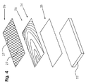
- Fig. 4 is represented as a support plate, a high density fiberboard 22 (HDF plate).
- the HDF board 22 is coated with a primer 23.
- a multi-layer decorative layer 24 is applied with a transparent sealing layer 25.
- a transparent antistatic layer 26 has been applied to the sealing layer 25 of the decorative layer 24.
- the antistatic layer 26 is made of a synthetic resin in which antimony-doped tin oxide-coated mica particles are dispersed. It is applied in mesh form and has particularly narrow strips 27.
- the strip width is 0.1 mm +/- 0.02 mm.
- the distance between the strips 27 to each other is 20 mm +/- 1 mm.
- the strips 27 each go continuously from a first outer edge, to a second outer edge of the wood-based panel.
- a primer 31 is applied on the surface of the wood-based panel 30, a primer 31 is applied.
- the primer 31 was dried and sanded before applying further layers.
- the antistatic layer 32 is applied above the primer 31 and formed as a particularly fine-meshed network, wherein the individual strips have a width of 1 mm +/- 0.1 mm and a distance of 10 mm +/- 1 mm. It was also dried after application. Due to this close-meshed network with stripes that are particularly wide in relation to the strip spacing, a particularly good shielding of electromagnetic radiation is possible.
- a multilayer decorative layer 33 and a sealing layer 34 of clear lacquer are arranged above the antistatic layer 32. All layers were applied by rollers.
- Fig. 5 shows an MDF board 38 on which an antistatic layer 40 is applied as a uniform network.
- the antistatic layer 40 consists of a 1-component polyurethane adhesive, which is mixed with 5 wt .-% of a Minatec® pigment.
- the strips of antistatic layer 40 were applied at a uniform center distance of 50 mm +/- 1 mm. The liquid applied strips are slightly worn after application, so that the strip width is about 3 mm +/- 2 mm.
- a decorative layer 41 and a sealing layer 42 in the form of melamine-treated papers. Charging of persons in a design according to FIG. 6 is measured according to DIN 1815 about 1kV.
- a three-layer not belonging to the invention overlay for pressing on a wood-based panel is shown.
- the outermost layer of the overlay, the sealant layer 35 is made by a carrier paper soaked with a transparent resin.
- a decorative paper 36 which was also soaked with a resin disposed.
- an antistatic layer 37 was applied liquid after drying the decorative layer.
- the antistatic layer 37 is designed as a grid with longitudinal and horizontal stripes.
- the strip width is 0.5 mm +/- 0.1 mm, the strip spacing 30 mm +/- 1 mm.
- the antistatic layer 37 consists of an adhesive filled with graphite, which was applied by means of rollers on the underside of the decorative paper 36 and dried under the action of warm air.
- the described application patterns in particular the strip and grid shape, the width and / or the distances of the grids / strips and the application methods are exemplary. Also, combined patterns are possible.
- application methods are not limited to the particular embodiment, but may be applied to compositions of matter and patterns of other embodiments.
- compositions of matter described in each case to an antistatic layer of a first exemplary embodiment with the application pattern of a further exemplary embodiment.
- fabric combinations described above i. the combinations of particles and / or adhesives and / or synthetic resins and / or paints listed by way of example only, not to be construed as exhaustive to understand and combined with each other.
Description
- Die Erfindung betrifft eine Holzwerkstoffplatte für Wand-, Boden- oder Deckenelemente, mit einer mehrlagigen Oberflächenbeschichtung, wobei mindestens eine Lage der Oberflächenbeschichtung als Flüssigkeit aufgetragen ist, abschnittsweise aufgetragen ist und elektrisch leitende Partikel enthält. Weiter betrifft die Erfindung ein Overlay gemäß Anspruch 14 und ein Verfahren gemäß Anspruch 15.
- Beschichtete Holzwerkstoffplatten, die bspw. als Laminat, Paneel, Verkleidung oder auch Arbeitsplatte verwendet werden, können eine statische Aufladung bei Personen bewirken. Insbesondere bei Fußbodenelementen, wie bspw. Laminatböden, ist es bekannt, dass eine das Laminat begehende Person eine statische Aufladung erfahren kann. Diese statische Aufladung gibt eine Person beim Berühren eines elektrisch leitenden Bauteils wie bspw. einer Türklinke oder eines Heizkörpers wieder ab. Dabei kann sie einen leichten, aber unangenehmen elektrischen Schlag erhalten. Solche elektrischen Schläge sind ab einer Aufladung von ca. 3.000 V deutlich spürbar.
- Um die statische Aufladung von Personen zu verhindern, sind sogenannte "antistatische Bodenbeläge" bekannt. Die deutsche Patentanmeldung
DE 103 01 293 A1 schlägt bspw. vor, Stege aus elektrisch leitendem Draht oder ein Drahtgewebe in die Oberflächenbeschichtung einer Holzwerkstoffplatte zu integrieren. - Die europäische Patentanmeldung
EP 1 681 103 A2 geht ebenfalls auf das Problem der statischen Aufladung von Personen ein und beschreibt einen antistatischen Bodenbelag mit einer ableitfähigen Oberfläche, bei der eine oberhalb des Dekors angeordnete, transparente Schicht mit ableitfähigen Partikeln aufgetragen wird. Problematisch hierbei ist das Erzeugen einer vollständig transparenten Schicht, um ein Dekor, wie bspw. eine Holzmaserung, auf der Plattenoberseite nicht zu verdecken. - Auch die
EP 2 272 667 beschreibt ein Paneel, bei dem eine vollflächig aufgetragene Lage mit antistatischen wirksamen Additiven in der Oberflächenbehandlung integriert wird. - Die
DE 10 2005 024 438 A1 beschreibt ein Paneel mit einer an der Unterseite angeordneten Klebstoffschicht, die elektrisch leitende Partikel enthalten kann. - Die Druckschrift
DE 693 163 46 T2 zeigt einen HPL und einen LPL-Schichtstoff zum Beschichten von Holzwerkstoffplatten, der mindestens eine Papierfolie enthält, die mit antistatischen Partikeln versetzt bzw. beschichtet ist. Als leitende Partikel werden Pigmente die bspw. aus Glimmerpartikeln bestehen, die mit einer Schicht mit Antimon dotiertem Zinnoxid überzogen sind offenbart. - Die Druckschrift
DE 203 18 290 U1 offenbart ein Overlay zum Beschichten von Paneelen mit ebenfalls antistatischen Eigenschaften. Zur Herstellung der antistatischen Eigenschaften werden quaternäre Ammoniumverbindungen in die Harzmischung mit eingebracht. Das Overlay wird mit dieser Harzmischung getränkt oder vollflächig beschichtet. - Sowohl die eingebrachten Metalldrähte in die Oberflächenbeschichtung, als auch die weiteren Oberflächenschichten mit elektrischer Ableitfähigkeit erzeugen eine antistatisch wirksame Beschichtung. Alle Lösungen greifen jedoch massiv in den normalen Aufbau von Oberflächenbeschichtungen für Holzwerkstoffe ein und stören diesen nachhaltig. Dies kann sich bspw. dahin gehend äußern, dass sich die Anpassung der Prozessparameter an die jeweils antistatisch wirksame Schicht als äußerst schwierig darstellt. Auch können die antistatisch wirksamen Schichten zu deutlich erhöhten Produktionskosten führen. Hinzu kommt, dass sich bei allen Lösungen die ableitfähige Schicht in ihren Eigenschaften, wie bspw. der Haftfähigkeit, deutlich von den übrigen Schichten der Oberflächenbeschichtung unterscheidet, so dass Delaminierungseffekte auftreten können.
- Der Erfindung liegt die Aufgabe zugrunde, eine Holzwerkstoffplatte mit Oberflächenbeschichtung und ein Verfahren zum Herstellen einer ableitfähigen Oberflächenbeschichtung bereitzustellen, wobei die Oberflächenbeschichtung die statische Aufladung einer Person verhindert und bei der die Delaminierung der Oberflächenbeschichtung verhindert wird. Ferner liegt der Erfindung die Aufgabe zugrunde, ein Overlay bereit zustellen, dass die statische Aufladung einer Person verhindert und bei der die Delaminierung des Overlays verhindert wird.
- Die Aufgabe wird gelöst mit einer Holzwerkstoffplatte gemäß Anspruch 1 und einem Verfahren gemäß Anspruch 15. Vorteilhafte Weiterbildungen der Erfindung sind in den abhängigen Ansprüchen angegeben.
- Die eine Lage (im Weiteren "antistatische Lage" genannt) ist erfindungswesentlicher Bestandteil einer mehrlagigen Oberflächenbeschichtung (im Weiteren auch "Beschichtungssystem") wie bspw. ein mehrteiliges Lacksystem. Dabei kann das Aufbringen dieser antistatischen Lage besonders vorteilhaft in den Ablauf des normalen Beschichtungsprozesses der Holzwerkstoffplatte integriert werden. Auch ist es möglich, sie in einem eigenständigen Prozessschritt vor oder nach den weiteren Schichten der Oberflächenbeschichtung aufzutragen.
- Beim Auftragen der antistatischen Lage ist es möglich, diese einschichtig oder auch mehrschichtig aufzutragen. Es können bspw. mehrere dünne Schichten übereinander aufgetragen werden, die nach dem Trocknen die antistatische Lage bilden. Hierbei ist es möglich, jede einzelne Schicht nach dem Auftragen und vor dem Auftrag der nächsten Schicht zu trockenen, anzugelieren oder auch alle Schichten im Nass-in-Nass-Verfahren aufzutragen. Gleiches gilt für die weiteren Lagen des mehrlagigen Beschichtungssystems.
- Bestandteil des mehrlagigen Beschichtungssystems können auch mehrere Lagen der antistatischen Lage sein. Dabei müssen diese Lagen nicht zwangsläufig direkt aneinandergrenzen, sondern es können auch Schichten aus anderen Werkstoffen (wie bspw. Lackschichten) zwischen den antistatischen Lagen angeordnet sein.
- Die Position der antistatischen Lage in einem Beschichtungssystem ist beliebig. Daher ist es nicht notwendig, dass die antistatische Lage als äußerste Lage der Oberflächenbeschichtung aufgetragen ist. Sie kann bspw. direkt auf die Holzwerkstoffplatte, auf einen Haftgrund und/oder auch unter-/oberhalb einer Grundierung, eines Dekors oder weiterer einzelner Lagen aufgetragen sein. Sie wird erfindungsgemäß flüssig aufgetragen und ist entweder selbsttrocknend oder wird durch Einwirken von Wärme oder Strahlung getrocknet oder ausgehärtet.
- Eine Holzwerkstoffplatte weist zwei Hauptoberflächen auf. Dies sind zum einen die Vorderseite und zum anderen die Rückseite. Als Vorderseite wird meistens die Sichtseite d. h. die Nutzseite bezeichnet. Die Rückseite ist die der Vorderseite gegenüberliegende Seite. Sie ist im montierten Zustand einer Raumbegrenzungsfläche wie bspw. einem Fußboden, einer Wand oder Decke zugewandt. Bei Verwendung der Holzwerkstoffplatte als bspw. Raumteiler kann sowohl die Vorder- als auch die Rückseite eine Sichtseite sein. Im Rahmen dieser Anmeldung werden unter der Bezeichnung Oberfläche sowohl die Vorderseite (Sichtseite oder Oberseite) und/oder die Rückseite und/ oder die Kanten der Holzwerkstoffplatte verstanden. Die antistatische Lage ist vorteilhaft auf die Vorderseite der erfindungsgemäßen Holzwerkstoffplatte aufgetragen.
- Oberflächenbeschichtungen von Holzwerkstoffplatten können -ebenso wie die antistatische Lage - bspw. flüssig aufgetragen werden. Hierfür werden insbesondere Lacke, Kunststoffe, Kunstharze, Kleber, flüssige Overlays, allgemein Dispersionen oder Suspensionen, Leim oder auch gelförmige Mittel verwendet. Die antistatische Lage kann aus einem oder mehreren dieser oben genannten Flüssigkeiten bestehen. Diese können zusätzlich teilweise eingefärbt, d. h. farbig oder mehrfarbig ausgebildet oder auch farblos, das bedeutet transparent sein.
- Grundsätzlich sind auch feste Oberflächenbeschichtungen bekannt. Hierzu gehören insbesondere Overlays und Dekorpapiere oder im Allgemeinen bahnenförmige Werkstoffe, die bspw. mit Kunstharz getränkt sind und auf eine Holzwerkstoffplatte aufgetragen werden. Die antistatische Lage kann auch Bestandteil eines solchen festen Beschichtungssystems sein, wobei sie dann erfindungsgemäß flüssig auf oder unter das feste Beschichtungssystem aufgetragen ist.
- Auch ist es denkbar, das die antistatische Lage Teil eines kombinierten Beschichtungssystems ist, wobei dieses teilweise flüssig, teilweise fest sein kann und in dem die antistatische Lage als Bestandteil integriert ist. Die antistatische Lage der erfindungsgemäßen Holzwerkstoffplatte kann in allen üblichen Oberflächenbeschichtungssystemen verwendet werden.
- Die antistatische Lage wird unabhängig von der Art des weiteren Beschichtungssystems grundsätzlich als Flüssigkeit aufgetragen. Unter einer Flüssigkeit ist im Rahmen dieser Anmeldung bspw. jede der oben aufgeführten Substanzen zu verstehen. Diese sind mit üblichen Auftragsverfahren oder auch Druckverfahren für flüssige Substanzen auf die Holzwerkstoffplatte aufzutragen. Hierzu gehören insbesondere Verfahren zum Spritzen, Streichen, Walzen oder auch Digitaldruckverfahren wie bspw. das Drucken mit Tintenstrahldruckern.
- Die für die eine Lage zu verwendenden elektrisch leitenden Partikel sind weitestgehend bekannt. Hierbei offenbart insbesondere die aus dem Stand der Technik bekannte
EP 1 681 103 A1 eine Vielzahl von unterschiedlich verwendbaren Partikeln. - Die antistatische Lage wird erfindungsgemäß abschnittsweise aufgetragen. Darunter ist zu verstehen, dass die antistatische Lage, wenn sie bspw. auf die Oberseite, d. h. die Vorderseite der Holzwerkstoffplatte aufgetragen wird, diese Seite nicht vollständig bedeckt. Es sind also zwangsläufig Bereiche auf der Vorderseite der Holzwerkstoffplatte, die von der antistatischen Lage bedeckt sind und Bereiche, die nicht bedeckt sind. Die antistatische Lage kann in unterschiedlichsten geometrischen Formen oder auch Anordnungen aufgetragen sein. Hier sind bspw. punktförmiges Auftragen, das Auftragen von mehreren Flecken oder das Auftragen von bestimmten Mustern denkbar.
- Insbesondere kann die antistatische Lage streifenförmig oder in Form eines Gitters ausgeführt werden. Die Streifen können dabei als Gerade und/oder als nicht linear verlaufende Streifen aufgetragen werden. Auch können bspw. einzelne Streifen in Wellen- oder Zackenform entlang einer Geraden aufgetragen sein.
- Die Streifen können bezogen auf die Holzwerkstoffplatte in Längsrichtung und/oder auch in Querrichtung verlaufen. Auch Streifen, die bogenförmig, diagonal oder in unterschiedliche Richtungen verlaufen, sind denkbar. Das geometrische Muster, das die Streifen bildet, ist beliebig.
- Unter einem Gitter wird im Sinne dieser Erfindung eine gleichmäßige Verteilung der Streifen verstanden. Dabei können bspw. die Streifenbreite und/oder auch die Streifenabstände gleichmäßig sein. Ein Gitter kann bspw. aus Streifen bestehen, die parallel zueinander ausgerichtet sind. Auch sind Gitter denkbar, in den eine erste Gruppe paralleler Streifen mit einem Winkel von bspw. 90° zu einer zweiten Gruppe paralleler Streifen ausgerichtet ist.
- Ein besonderer Vorteil der erfindungsgemäßen Holzwerkstoffplatte mit der antistatischen Lage ist, dass durch den abschnittsweisen Auftrag der antistatischen Lage zwischen den einzelnen Bereichen in denen die antistatische Lage aufgetragen ist, Bereiche (Zwischenräume) entstehen, die nicht mit der antistatischen Lage bedeckt sind. Dadurch ist die gesamt aufzutragende Menge der antistatischen Lage deutlich geringer, als wenn die antistatische Lage bspw. die Vorderseite vollständig bedeckt.
- Der vorteilhafte abschnittsweise Auftrag der antistatischen Lage gewährleistet, dass sich in den freien Abschnitten, die nicht von der antistatischen Lage abgedeckt sind, oberund unterhalb der antistatischen Lage angeordnete Lagen- und damit deren Oberflächen- direkt miteinander verbinden können. Über diese direkte Verbindung ist ein besonders fester Verbund der ober- und unterhalb der antistatischen Lage befindlichen Lagen/Oberflächen möglich. Dieser direkte Verbund der einzelnen Oberflächenlagen entspricht der bekannten Verbindung in Beschichtungssystemen ohne antistatische Lage.
- Der abschnittsweise Verbund der unter- und oberhalb der antistatischen Lage angeordneten Lagen/Oberflächen verhindert bspw. eine Delaminierung einzelner Schichten eines mehrschichtigen Oberflächensystems aufgrund von zu geringen Hafteigenschaften der antistatischen Lage.
- Hinzu kommt, dass Prozessparameter wie bspw. Presstemperaturen, Auftragstemperaturen und Trocknungsgeschwindigkeiten für weitere Lagen der Oberflächenbeschichtung durch die nur abschnittsweise aufgetragene antistatische Lage nur geringfügig angepasst werden müssen.
- Gemäß einer besonders bevorzugten Weiterbildung der Erfindung erfolgt, durch einen ausreichend hohen Einsatz elektrisch leitender Partikel und ausreichend viele und/oder breite Streifen der die leitfähigen Partikel enthaltenden Flüssigkeit beim Begehen der Platte eine Personenaufladung von weniger als 2.000 V. Diese Personenaufladung wird üblicherweise über ein Verfahren, das in der Norm DIN 1815 beschrieben wird, bestimmt. Weiter wird eine Ausführungsform besonders bevorzugt, bei der die Norm EN 14041 erfüllt ist und die Holzwerkstoffplatte gemäß dieser Norm als "antistatischer Bodenbelag" bezeichnet werden kann.
- Die antistatische Lage kann - wie bereits beschrieben - unterschiedlich aufgetragen und ausgerichtet sein. Insbesondere ist sie jedoch in Form von regelmäßig oder unregelmäßig verteilten Streifen aufgetragen. Diese Streifen weisen besonders bevorzugt eine Breite zwischen 40 mm - 0,05 mm, bevorzugt zwischen 20mm und 0,5 mm, besonders bevorzugt zwischen 15 mm und 0,75 mm, vorzugsweise zwischen 12,5 mm und 1,0 mm vorteilhafter Weise zwischen 10 mm und 1 mm und besonders vorteilhaft zwischen 5 mm und 2 mm auf.
- Die Breite der Streifen kann sich bspw. nach der Anzahl der Streifen richten. Je breiter der einzelne Streifen ist, desto weniger Streifen sind auf der Oberfläche der Holzwerkstoffplatte notwendig. Die Streifen auf einer Oberfläche können auch unterschiedlich breit ausgelegt sein. So ist es bspw. möglich, besonders breite Streifen und besonders schmale Streifen gemeinsam auf eine Oberfläche der Holzwerkstoffplatte aufzutragen. Auch regelmäßige Muster sind hier denkbar. Es können bspw. besonders breite Streifen in Längsrichtung der Platte und besonders schmale Streifen in Querrichtung der Platte aufgetragen werden. Durch die Gestaltung der Streifen kann ein Optimum von Materialeinsatz und Leitfähigkeit eingestellt werden.
- Besonders bevorzugt sind die aufgetragenen Streifen zumindest teilweise miteinander verbunden. Dies kann bspw. durch in Längs- als auch in Querrichtung aufgetragene Streifen erfolgen. Auch unregelmäßige oder bogenförmige, z.B. kreuzend angeordnete Streifen können mehrere Streifen miteinander verbinden. Die Streifen können sich überlappen oder auch nur aneinanderstoßen. Solche Verbindungen -unabhängig davon, ob überlappend oder aneinanderstoßend- werden im Rahmen dieser Anmeldung als Knotenpunkte bezeichnet. Es müssen nicht alle aufgetragenen Streifen untereinander verbunden sein, eine Vielzahl von Verbindungen ist jedoch von Vorteil, da die Ableitfähigkeit der Holzwerkstoffplatte verbessert wird.
- Aus diesem Grund sind gemäß einer besonders bevorzugten Weiterbildung der Erfindung die Streifen in Form eines regelmäßigen oder unregelmäßigen Netzes aufgetragen. In einem Netz bilden die einzelnen, aneinanderstoßenden Streifen eine Vielzahl von Knotenpunkten die alle Streifen untereinander verbinden. Diese können, wie bei den nicht netzförmig aufgetragenen Streifen bereits ausgeführt, sich überlappen oder auch nur aneinanderstoßen.
- Die Form des Netzes ist unterschiedlich zu gestalten. Es kann bspw. rhombische, quadratische, rechteckige, sechseckige oder auch allgemein polygonale Öffnungen (bei Netzen auch Maschen genannt) aufweisen. Auch sind kreis-/bogenförmige Öffnungen möglich. Es kann aber auch ein gänzlich unregelmäßiges Netz aufgetragen werden, in dem kein spezifisches Muster erkennbar ist. Besonders bevorzugt wird ein Netz mit einer hohen Anzahl an Knotenpunkten aufgetragen, da dadurch eine besonders gute Ableitfähigkeit elektrischer Ladungen gewährleistet ist. Die Knotenpunkte können - anders als beim Stand der Technik - so ausgebildet werden, dass sie die gleiche Stärke (Auftragsdicke) aufweisen, wie die übrigen Bereiche der antistatischen Lage.
- Besonders bevorzugt sind die Streifen oder auch das Gitter zumindest teilweise durchgängig auf bspw. eine Seite der Oberfläche aufgetragen. Durchgängig bedeutet, dass die Streifen ohne Unterbrechung von einer ersten Plattenkante zu einer zweiten Plattenkante aufgetragen sind. Die jeweiligen Plattenkanten können sich gegenüber liegen oder auch aneinandergrenzen. Hierdurch ist eine besonders gute Ladungsverteilung an der Oberfläche gegeben.
- Bei Verwendung der Holzwerkstoffplatte als Fußbodenelement sollte der Abstand der Streifen zueinander oder auch bspw. die Maschengröße bei Auftrag eines Netzes nicht größer sein als die Länge eines menschlichen Fußes. Dadurch wird gewährleistet, dass eine das Fußbodenelement begehende Person immer mindestens zwei Streifen gleichzeitig "berührt".
- Besonders bevorzugten beträgt der Abstand zwischen den Einzelnen durch die antistatische Lage bedeckten Abschnitten zwischen 1 mm und 60 mm, bevorzugt zwischen 5mm und 30mm, besonders bevorzugt zwischen 7,5 mm und 20 mm, vorzugsweise zwischen 10mm und 15mm, vorteilhaft 12,5 +/- 2mm beträgt.
- Um sowohl eine ausreichende elektrische Ableitfähigkeit der antistatischen Lage als auch eine ausreichende Haftung der einzelnen Lagen untereinander zu erreichen, ist die antistatische Lage nur abschnittsweise auf die bspw. Vorderseite (Sichtseite) der Holzwerkstoffplatte aufgetragen. Entscheidend für das optimale Ergebnis kann also das Verhältnis zwischen Gesamtoberfläche der bspw. Vorderseite und der durch die antistatische Lage abgedeckten Oberfläche der Vorderseite sein. Hierbei bedeutet bspw. eine 100%-ige Abdeckung der Vorderseite, dass die antistatische Lage vollständig auf die Vorderseite aufgetragen ist.
- Gemäß einer besonders bevorzugten Weiterbildung der Erfindung ist die eine Lage auf eine Sichtseite der Holzwerkstoffplatte aufgetragen und bedeckt zwischen 50% und 1%, besonders bevorzugt zwischen 25% und 1%, vorteilhaft zwischen 10% und 1%, besonders vorteilhaft zwischen 5% und 1% und vorzugsweise weniger als 1 % der Sichtseite.
- Neben der üblichen Auftragsweise der antistatischen Lage als regelmäßig oder unregelmäßig verteilte Streifen ist es nach einer besonderen Weiterbildung der Erfindung möglich, dass die antistatische Lage an ein Muster eines Dekors angepasst ist. Hier ist es bspw. denkbar, die antistatische Lage besonders dunkel einzufärben und mit dieser dunkel eingefärbten Lage bspw. dunkle Jahrringe eines Holzdekors oder auch Poren eines Holzdekors nachzubilden. Auch denkbar wäre es, die antistatische Lage besonders dick aufzutragen, so dass die antistatische Lage eine besondere, an das Dekor angepasste Haptik erzeugt.
- Die antistatische Lage kann bei transparenter Ausführung bspw. oberhalb eines Dekors angeordnet sein. Bevorzugt ist die antistatische Lage, jedoch unterhalb einer ein Dekor bildenden Lage, aufgetragen. Der besondere Vorteil hierbei ist, dass bspw. auf die Farbe der antistatischen Lage keine Rücksicht genommen werden muss. Diese kann besonders dunkel, mehrfarbig, einfarbig oder transparent ausgebildet sein. Aufgrund dessen, dass die antistatische Lage von einer dekorbildenden Schicht überdeckt wird, ist sie nicht sichtbar. Damit besteht die vorteilhafte Möglichkeit, die antistatische Lage ausschließlich auf ihre ableitfähigen Eigenschaften einzustellen, ohne dass weitere besondere Eigenschaften, wie bspw. Transparenz beachtet werden müssen.
- Nach einer besonders bevorzugten Weiterbildung besteht die antistatische Lage aus einem im ausgehärteten Zustand mit elektrisch leitenden Partikeln gefüllten PVAC-Kleber oder PUR-Kleber. PVAC-Kleber sind mit allen üblichen Auftrags- und Druckverfahren auf eine Oberfläche aufzutragen und besonders gut in übliche Oberflächenbeschichtungen zu integrieren. Hinzu kommt, dass PVAC-Kleber kostengünstig sind.
- Besonders bevorzugt besteht die antistatische Lage im flüssigen Zustand aus einem im ausgehärteten Zustand mit Kohlenstoff-Nanotubes gefüllten Kleber. Dieser kann bspw. als Suspension die Kohlenstoff-Nanotubes enthält aufgetragen werden. Die Kohlenstoff-Nanotubes weisen eine besonders gute Ableitfähigkeit auf, so dass es möglich ist, mit nur geringen Mengen an Kohlenstoff-Nanotubes eine besonders gute Ladungsverteilung zu erreichen. Dadurch können besonders einfach antistatischen Eigenschaften der Holzwerkstoffplatte hergestellt werden.
- Nach einer vorteilhaften Weiterbildung der Erfindung sind die elektrisch leitfähigen Partikel, bspw. Partikel aus Ruß, Graphit oder Metall. Diese Partikel sind besonders einfach in übliche Flüssigkeiten zur Oberflächenbeschichtung zu integrieren und kostengünstig. Unabhängig von der Art der Partikel ist auch die Form der Partikel beliebig. So kann es sich bspw. um besonders flache, runde oder längliche, und/oder auch um Flakes, Fasern, Tubes, Hohlkörper oder Gemische dieser unterschiedlichen Partikel handeln.
- Gemäß einer bevorzugten Weiterbildung der Erfindung enthält die eine Lage im flüssigen Zustand als elektrisch leitfähige Partikel hochkonzentrierte Salze. Salze können hervorragende elektrische Leiter sein, sind besonders einfach in der Flüssigkeit zu verteilen und mit der Flüssigkeit aufzutragen. Sie eignen sich in besonders vorteilhafterweise zum direkten Auftrag auf die Holzwerkstoffplatte oder unterhalb einer Dekorschicht.
- Bevorzugt werden quaternäre Ammoniumsalze, Alkalisalze, Perflouralkylsulfonat, oder Perflouralkylsulfonylamide verwendet. Besonders bevorzugt werden mit Antimon dotiertem Zinnoxid beschichtete Glimmer-Partikel verwendet, wie bspw. leitfähige Minatec®-Pigmente. Es können jedoch auch alle weiteren Salze/Pigmente verwendet werden, die eine elektrische Leitfähigkeit der einen Lage herstellen.
- Die aufzutragende Flüssigkeitsmenge, aus der die antistatische Lage gebildet wird, ist von unterschiedlichen Faktoren abhängig. Dies kann bspw. die Anzahl der elektrisch leitenden Partikel pro Mengeneinheit oder auch pro Flächeneinheit sein. Sie kann jedoch bspw. auch durch die Breite der einzelnen Streifen bzw. durch den Abdeckungsgrad der Oberfläche durch die antistatische Lage bestimmt werden. Die Flüssigkeit besteht bevorzugt aus vernetzbaren Monomeren, ggf. mit Anteilen von Wasser oder Lösungsmittel.
- Der Anteil an elektrisch leitenden Partikeln in der Flüssigkeit kann bspw. abhängig von der Art der Partikel und insbesondere von der Form der Partikel sein. Bei elektrisch leitenden Fasern ist ein erheblich geringer Anteil notwendig als bei bspw. runden leitfähigen Partikeln, da bei Fasern eine stärkere Überlappung der einzelnen Fasern und damit eine bessere Leitfähigkeit zwischen den Fasern erreicht wird. Üblich ist eine Menge von elektrisch leitfähigen Partikeln in der Flüssigkeit, die ca. 2% bis 8% des Gewichtes der Flüssigkeit mit der sie aufgetragen werden entspricht. Bei bspw. Karbonfasern sind Mengen von ca. 2% bis max. 7% notwendig. Wie bei der aufzutragenden Flüssigkeitsmenge ist auch der Anteil an elektrischen Partikeln in der Flüssigkeit von vielen Faktoren abhängig. Diese können zum einen die partikelspezifischen Eigenschaften (wie bspw. Art, Form, Größe, Leitfähigkeit, usw.) und zum anderen die auftragspezifischen Eigenschaften (Auftragsform, Vernetzung der Partikel untereinander, usw.) sein.
- Zusätzlich zu der Beschichtung der bspw. Vorderseite und/oder Rückseite können auch die Seitenflächen -die ebenfalls zur Oberfläche der Holzwerkstoffplatte gehören- mit beschichtet werden. Insbesondere bei der Ausgestaltung der Holzwerkstoffplatte als Paneel, das heißt mit einem Verbindungsprofil zum Verbinden mehrerer Holzwerkstoffplatten ist der weiterführende Auftrag der Stege oder des Gitters auf die Seitenflächen denkbar.
- Durch Beschichtung von bspw. der Seitenflächen / Profile mit der antistatischen Lage, ist es möglich, über mehrere miteinander verbundene Holzwerkstoffplatten einen Austausch elektrischer Ladungen zu erreichen. Hierdurch kann in besonders vorteilhafter und einfacher Weise ein bspw. "antistatischer Bodenbelag" hergestellt werden.
- Auch kann ein Overlay, welches zum Beschichten einer Trägerplatte aus bspw. Holzwerkstoffen geeignet ist, mindestens eine antistatische Lage
aufweisen, die als Flüssigkeit aufgetragen ist, die abschnittsweise aufgetragen ist und elektrisch leitende Partikel enthält. Auch Overlays weisen eine Vorder- und eine Rückseite auf. Wie bei den Holzwerkstoffplatten wird unter der Vorderseite des Overlays die Seite verstanden, die bspw. sichtbar ist oder als Nutzfläche verwendet wird. Als Rückseite ist beim Overlay die Seite zu verstehen, die zur Trägerplatte weist. Die antistatische Lage kann dabei auf der Vorderseite oder auch auf der Rückseite des Overlays aufgetragen sein. - Im Folgenden werden Details der Erfindung anhand von Ausführungsbeispielen näher erläutert. Es zeigt
- Fig.1
- eine schematische Darstellung eines ersten Ausführungsbeispiels mit einer direkt auf eine Holzwerkstoffplatte gitterförmig aufgetragenen antistatischen Lage;
- Fig.2
- eine schematische Darstellung eines zweiten Ausführungsbeispiels mit einer antistatischen Lage unterhalb einer Dekorschicht;
- Fig.3
- eine schematische Darstellung eines weiteren Ausführungsbeispiels mit einer gitterförmig aufgetragene antistatischen Lage;
- Fig.4
- eine schematische Darstellung eines weiteren Ausführungsbeispiels mit einer netzförmigen, transparenten antistatischen Lage;
- Fig.5
- eine schematische Darstellung eines weiteren Ausführungsbeispiels mit einer netzförmigen, transparenten antistatischen Lage
- Fig.6
- eine schematische Darstellung eines Overlay mit antistatischer Lage zum Beschichten von Trägerplatten.
- Eine in
Fig. 1 dargestellte Holzwerkstoffplatte, eine HDF-Platte 1 (hochdichte Faserplatte), weist eine mehrschichtige Oberflächenbeschichtung auf, auf deren Vorderseite ausgehend von der Oberfläche der HDF-Platte 1, eine abschnittsweise aufgetragene Lage 2 mit elektrischen Partikeln (antistatische Lage), ein Schicht aus Grundierung 3, ein Dekor 4 und eine Versiegelungsschicht 5 aufgetragen ist. Die Oberflächenbeschichtung der, der Vorderseite gegenüber liegenden Rückseite und der Kanten der HDF-Platte 1 ist hiervon abweichend aufgebaut. - Die antistatische Lage 2 ist gitterförmig aufgetragen. Das Gitter besteht aus Längsstreifen 6 und Querstreifen 7. Die Längsstreifen 6 verlaufen parallel zu einer längeren Außenkante der HDF-Platte 1, die Querstreifen 7 verlaufen parallel zu einer gegenüber der Längeren Außenkante kürzeren Außenkante der HDF-Platte 1. Der Winkel zwischen Längs- und Querstreifen 6,7 beträgt 90° +/- 1°. Die Streifen 6,7 können aber bspw. auch in einem scherenförmigen Muster verlaufen. Der Winkel zwischen den Streifen 6, 7 des antistatisch wirkenden Materials kann bspw. zwischen 50° und 170° betragen, je nach Art des Materials, Anforderung an die antistatischen Eigenschaften der Oberflächenbeschichtung oder der Position der antistatischen Lage 2 in der Oberflächenbeschichtung. Die Längsstreifen 6 und Querstreifen 7 berühren sich, so dass Knotenpunkte 8 ausgebildet werden, über die eine Ladungsverteilung erfolgen kann. Die Knotenpunkte 8 weisen die gleiche Materialstärke auf wie die Streifen 6, 7. Die Längsstreifen 6 sind mit ungleichmäßigem Abstand jedoch parallel zueinander aufgetragen. Sie sind immer paarweise aufgetragen, so dass jeweils zwei Streifen mit einem Abstand von jeweils 10 mm +/- 1 mm zueinander und einem Abstand von 60 mm +/- 1 mm zum nächsten Streifenpaar aufgetragen sind. Die Querstreifen 7 werden gleichmäßig parallel mit einem Abstand von 40 mm +/- 1 mm zueinander aufgetragen. Die Breite der Streifen 6,7 beträgt durchgängig 0,5 mm +/- 0,1 mm. Die Vorderseite der Holzwerkstoffplatte ist damit zu 2,2 % durch die antistatische Lage 2 abgedeckt.
- Die antistatische Lage 2 ist flüssig mit einer Walze aufgetragen und wurde mit dem Auftrag durch Passieren eines Warmluftofens getrocknet. Sie besteht aus einem Polyurethanklebstoff der mit einem Minatec®-Pigment versetzt ist. Der Mengenanteil des Minatec®-Pigment beträgt 5 Gew. % bezogen auf den Polyurethanklebstoff. Der Polyurethanklebstoff ist ein 1-Komponenten-Klebstoff. Es können jedoch auch 2-Komponenten Polyurethanklebstoffe verwendet werden. Alternativ kann bspw. auch ein PVAC-Kleber, der hochkonzentrierte elektrisch leitfähige Salze beinhaltet verwendet werden.
- In
Fig. 2 ist als Trägerplatte eine Spanplatte 9 dargestellt. Ausgehend von der Oberfläche der Spanplatte 9 ist eine Grundierungsschicht 10 auf die Spanplatte 9 aufgetragen worden. Ggf. kann vor der Grundierung 10 auch noch eine Schicht Haftgrund auf die Spanplatte 9 aufgetragen werden. Auf die Grundierung 10 und unterhalb einer Dekorlage 15 ist die antistatische Lage 11 aufgebracht. Die Streifen 12 der antistatischen Lage 11 sind als Zickzack-Linien ausgebildet, weisen eine Streifenbreite von 12,5 mm +/- 1 mm auf und haben einen mittleren Abstand von 50 mm +/- 1 mm zueinander. Die antistatische Lage 11 besteht aus einem mit Karbonfasern gefüllten Kunstharz, welches mit einer Dicke von 30 µm aufgetragen wurde und nach dem Auftragen durch Elektronenstrahlhärtung getrocknet wurde. Alternativ kann bspw. eine Suspension aus einem PVAC-Kleber mit Kohlenstoff-Nanotubes verwendet werden. Die Streifen 12 verlaufen ohne Unterbrechung von einer ersten Außenkante 13 zu einer der ersten Außenkante 13 gegenüberliegenden, zweiten Außenkante 14. Die antistatische Lage 11 wurde mit Walzen aufgetragen und mit Hilfe von Warmluft angeliert, jedoch nicht ausgehärtet. Oberhalb der antistatischen Lage 11 ist die Dekorlage 15 angeordnet, die aus mehreren einzelnen Schichten besteht. Die Dekorlage 15 wurde ebenso wie die antistatische Lage 11 flüssig mit Hilfe von Walzen aufgetragen. Den äußeren Abschluss der Oberflächenbeschichtung bildet eine flüssige Versiegelungsschicht 16 aus Kunstharz, ein sogenanntes flüssiges Overlay auf Melaminharzbasis, das mit Cellulosefasern versetzt ist. Abschließend wurden alle Schichten in einer Kurztaktpresse unter Einwirkung von Druck und Wärme ausgehärtet. - In
Fig. 3 wird ein ähnlicher Schichtaufbau wie inFig. 2 dargestellt. Als Trägerplatte 20 wird eine Furnierholzplatte 20 verwendet. Die antistatische Lage 17 ist ebenfalls als Gitter mit gleichmäßig verteilten parallel zueinander ausgerichteten Streifen 18 (mit Wabenschraffur dargestellt) auf die getrocknete und geschliffene Grundierung 19 aufgetragen. Die Streifen 18 sind jedoch in einem Winkel von ca. 30° zu einer Längskante 20 der Furnierholzplatte 20 ausgerichtet. Die Breite der Streifen 18 beträgt 40 mm +/- 1 mm und der Abstand zwischen den Streifen 18 45 mm +/- 1 mm. Hierdurch bedeckt die antistatische Lage 17 ca. 47% der Oberfläche der Sichtseite. Die antistatische Lage 17 besteht aus einem mit Rußpartikeln gefüllten Kunstharz, der durch Digitaldruck aufgetragen und unter Strahleneinwirkung getrocknet wurde. Oberhalb der antistatischen Lage 17 ist ein Dekorpapier 21a und ein transparentes Overlaypapier 21b angeordnet, die beide mit Melaminharz getränkt sind. Abschließend wurden alle Schichten unter Einwirkung von Druck und Wärme ausgehärtet. - In
Fig. 4 wird als Trägerplatte eine hochdichte Holzfaserplatte 22 (HDF-Platte) dargestellt. Die HDF-Platte 22 ist mit einer Grundierung 23 beschichtet. Auf die Grundierung 23 ist eine mehrschichtige Dekorlage 24 mit transparenter Versiegelungsschicht 25 aufgetragen. Abschließend ist eine transparente antistatische Lage 26 auf die Versiegelungsschicht 25 der Dekorlage 24 aufgetragen worden. Die antistatische Lage 26 besteht aus einem Kunstharz in dem mit Antimon dotiertem Zinnoxid beschichte Glimmerpartikel dispergiert wurden. Sie ist in Netzform aufgetragen und weist besonders schmale Streifen 27 auf. Die Streifenbreite beträgt 0,1 mm +/- 0,02 mm. Der Abstand der Streifen 27 zueinander beträgt 20 mm +/- 1 mm. Die Streifen 27 gehen jeweils durchgängig von einer ersten Außenkante, zu einer zweiten Außenkante der Holzwerkstoffplatte. - Auf die Oberfläche der Holzwerkstoffplatte 30 ist eine Grundierung 31 aufgetragen. Die Grundierung 31 wurde vor dem Auftragen weiterer Schichten getrocknet und geschliffen. Die antistatische Lage 32 ist oberhalb der Grundierung 31 aufgetragen und als besonders feinmaschiges Netz ausgebildet, wobei die einzelnen Streifen eine Breite von 1 mm +/-0,1 mm und einen Abstand von 10 mm +/- 1 mm aufweisen. Sie wurde nach dem Auftragen ebenfalls getrocknet. Durch dieses engmaschige Netz mit im Verhältnis zum Streifenabstand besonders breiten Streifen ist eine besonders gute Abschirmung elektromagnetischer Strahlung möglich. Oberhalb der antistatischen Lage 32 sind eine mehrschichtige Dekorlage 33 und eine Versiegelungsschicht 34 aus Klarlack angeordnet. Alle Schichten wurden mittels Walzen aufgebracht.
-
Fig. 5 zeigt eine MDF-Platte 38 auf die eine antistatische Lage 40 als gleichmäßiges Netz aufgetragen ist. Die antistatische Lage 40 besteht aus einem 1-Komponenten-Polyurethankleber, der mit 5 Gew.-% eines Minatec®-Pigmentes versetzt ist. Die Streifen der antistatischen Lage 40 wurden mit einem gleichmäßigen Mittelabstand von 50 mm +/- 1 mm aufgetragen. Die flüssig aufgetragenen Streifen sind nach dem Auftrag leicht verlaufen, so dass die Streifenbreite ca. 3 mm +/- 2 mm beträgt. - Oberhalb der antistatischen Lage 40 sind eine Dekorlage 41 und eine Versiegelungsschicht 42 in Form von mit Melamin beharzten Papieren aufgetragen. Die Personenaufladung bei einer Ausführung gemäß
Figur 6 beträgt gemessen nach DIN 1815 ca. 1kV. - In
Fig. 6 wird ein dreilagiges nicht zur Erfindung gehörendes Overlay zum Verpressen auf eine Holzwerkstoffplatte dargestellt. Die äußerste Schicht des Overlays, die Versiegelungsschicht 35, wird durch ein mit einem transparenten Harz getränktes Trägerpapier hergestellt. Unterhalb der Versiegelungsschicht ist ein Dekorpapier 36, welches ebenfalls mit einem Harz getränkt wurde, angeordnet. Auf die Unterseite des Dekorpapiers 36, das heißt auf die Seite, die im verpressten Zustand zur Oberfläche der Trägerplatte zeigt, wurde nach dem Trocknen der Dekorlage eine antistatische Lage 37 flüssig aufgetragen. Die antistatische Lage 37 ist als Gitter mit Längs- und Querstreifen ausgeführt. Die Streifenbreite beträgt 0.5 mm +/- 0,1 mm, der Streifenabstand 30 mm +/- 1 mm. Die antistatische Lage 37 besteht aus einem mit Graphit gefüllten Klebstoff, der mittels Walzen auf die Unterseite des Dekorpapiers 36 aufgetragen und unter Einwirkung von Warmluft getrocknet wurde. - Es können sowohl beim Overlay aus
Fig. 6 als auch bei den Ausführungsbeispielen aus denFiguren 1 - 5 weitere Lagen angeordnet sein. Denkbar sind bspw. Lagen mit verschleißfesten Bestandteilen wie z. B. Korund, weitere Trägerpapierlagen beim Overlay und/oder Lagen mit geringer Härte, die unter- und/oder oberhalb des Dekors angeordnet werden und der Verbesserung der schallisolierenden Eigenschaften dienen. - Die beschrieben Auftragungsmuster, insbesondere die Streifen-, Gitterform, die Breite und/oder die Abstände der Gitter/Streifen und die Auftragungsmethoden sind beispielhaft. Auch sind kombinierte Muster möglich.
- Ferner sind die Auftragungsmethoden nicht auf das jeweilige Ausführungsbeispiel beschränkt, sondern können auch für Stoffzusammensetzungen und Muster anderer Ausführungsbeispiele angewendet werden.
- Insbesondere ist es auch möglich, die jeweils beschriebenen Stoffzusammensetzungen einer antistatischen Lage eines ersten Ausführungsbeispiels mit dem Auftragungsmuster eines weiteren Ausführungsbeispiels aufzutragen. Weiter sind die vorab beschriebenen Stoffkombinationen, d.h. die Kombinationen von Partikeln und/oder Klebern und/oder Kunstharzen und/oder Lacken nur beispielhaft aufgeführt, nicht als abschließend aufgezählt zu verstehen und untereinander kombinierbar.
Claims (15)
- Holzwerkstoffplatte für Wand-, Boden- oder Deckenelemente mit einer mehrlagigen Oberflächenbeschichtung auf der Vorderseite der Holzwerkstoffplatte, wobei mindestens eine Lage (2, 11, 17, 26, 32, 37, 40) der Oberflächenbeschichtung- als Flüssigkeit aufgetragen ist,- abschnittsweise, als regelmäßig oder unregelmäßig verteilte Streifen (6, 7, 12, 18, 27) oder als Gitter aufgetragenen ist und- elektrisch leitende Partikel enthält.
- Holzwerkstoffplatte nach Anspruch 1, dadurch gekennzeichnet, dass beim Begehen der Platte eine Personenaufladung von weniger als 2000 V erfolgt.
- Holzwerkstoffplatte nach mindestens einem der vorangegangenen Ansprüche,
dadurch gekennzeichnet, dass die Streifen eine Breite zwischen 40 mm und 0,05 mm aufweisen. - Holzwerkstoffplatte nach mindestens einem der vorangegangenen Ansprüche,
dadurch gekennzeichnet, dass die aufgetragenen Streifen (6, 7, 12, 18, 27) zumindest teilweise miteinander verbunden sind. - Holzwerkstoffplatte nach mindestens einem der vorangegangenen Ansprüche,
dadurch gekennzeichnet, dass die Streifen (6, 7, 12, 18, 27) in Form eines regelmäßigen oder unregelmäßigen Netzes aufgetragen sind. - Holzwerkstoffplatte nach mindestens einem der vorangegangenen Ansprüche ,
dadurch gekennzeichnet, dass die Streifen (6, 7, 12, 18, 27) zumindest teilweise durchgängig von einer ersten Plattenkante zu einer zweiten Plattenkante aufgetragen sind. - Holzwerkstoffplatte nach mindestens einem der vorangegangenen Ansprüche,
dadurch gekennzeichnet, dass ein Abstand zwischen den einzelnen durch die eine Lage bedeckten Abschnitten zwischen 1 mm und 60 mm, beträgt. - Holzwerkstoffplatte nach mindestens einem der vorangegangenen Ansprüche,
dadurch gekennzeichnet, dass die eine Lage (2, 11, 17, 26, 32, 37, 40) auf eine Sichtseite der Holzwerkstoffplatte aufgetragen ist und dass die eine Lage (2, 11, 17, 26, 32, 37, 40) zwischen 50% und 1% bedeckt. - Holzwerkstoffplatte nach mindestens einem der Ansprüche 1 bis 7, dadurch gekennzeichnet, dass die eine Lage (2, 11, 17, 26, 32, 37, 40) auf eine Sichtseite der Holzwerkstoffplatte aufgetragen ist und dass die eine Lage (2, 11, 17, 26, 32, 37, 40) weniger als 1 % der Sichtseite bedeckt.
- Holzwerkstoffplatte nach mindestens einem der vorangegangenen Ansprüche,
dadurch gekennzeichnet, dass die eine Lage (2, 11, 17, 26, 32, 37, 40) an ein Muster eines Dekors angepasst ist. - Holzwerkstoffplatte nach mindestens einem der vorangegangenen Ansprüche,
dadurch gekennzeichnet, dass die eine Lage (2, 11, 17, 26, 32, 37, 40) unterhalb einer ein Dekor bildenden Lage aufgetragen ist. - Holzwerkstoffplatte nach mindestens einem der vorangegangenen Ansprüche,
dadurch gekennzeichnet, dass die eine Lage (2, 11, 17, 26, 32, 37, 40) aus einem im ausgehärteten Zustand mit elektrisch leitenden Partikeln gefüllten PVAC-Kleber besteht. - Holzwerkstoffplatte nach mindestens einem der vorangegangenen Ansprüche,
dadurch gekennzeichnet, dass die eine Lage (2, 11, 17, 26, 32, 37, 40) aus einem im ausgehärteten Zustand mit Kohlenstoff-Nanotubes gefüllten Kleber besteht. - Holzwerkstoffplatte nach mindestens einem der vorangegangenen Ansprüche,
dadurch gekennzeichnet, dass die elektrisch leitfähigen Partikel Partikel aus Ruß, Graphit, oder Metall sind und/oder die eine Lage (2, 11, 7, 26, 32, 37, 40) im flüssigen Zustand als elektrisch leitfähige Partikel hochkonzentrierte Salze enthält. - Verfahren zum Herstellen einer ableitfähigen Oberflächenbeschichtung mit den Schritten:- Abschnittsweise Auftragen mindestens einer Lage (2, 11, 17, 26, 32, 37, 40) als Flüssigkeit mit elektrisch leitenden Partikeln auf eine Vorderseite einer Holzwerkstoffplatte, wobei die eine Lage als regelmäßig oder unregelmäßig verteilte Streifen oder als Gitter aufgetragen wird,- zumindest teilweise Angelieren oder vollständiges Trocknen der einen Lage (2, 11, 17, 26, 32, 37, 40) und- Auftragen weiterer Lagen der Oberflächenbeschichtung wobei die eine Lage (2, 11, 17, 26, 32, 37, 40) vor und/oder nach den weiteren Lagen aufgetragen werden kann.
Priority Applications (6)
| Application Number | Priority Date | Filing Date | Title |
|---|---|---|---|
| ES11170803.8T ES2602708T3 (es) | 2011-06-21 | 2011-06-21 | Tablero de material derivado de la madera y procedimiento de producción |
| EP11170803.8A EP2537597B1 (de) | 2011-06-21 | 2011-06-21 | Holzwerkstoffplatte und Verfahren zur Herstellung |
| PL16170730T PL3090812T3 (pl) | 2011-06-21 | 2011-06-21 | Folia powłokowa overlay |
| PL11170803T PL2537597T3 (pl) | 2011-06-21 | 2011-06-21 | Płyta drewnopochodna oraz sposób jej wytwarzania |
| EP16170730.2A EP3090812B1 (de) | 2011-06-21 | 2011-06-21 | Overlayfolie |
| ES16170730T ES2772398T3 (es) | 2011-06-21 | 2011-06-21 | Lámina de revestimiento |
Applications Claiming Priority (1)
| Application Number | Priority Date | Filing Date | Title |
|---|---|---|---|
| EP11170803.8A EP2537597B1 (de) | 2011-06-21 | 2011-06-21 | Holzwerkstoffplatte und Verfahren zur Herstellung |
Related Child Applications (2)
| Application Number | Title | Priority Date | Filing Date |
|---|---|---|---|
| EP16170730.2A Division EP3090812B1 (de) | 2011-06-21 | 2011-06-21 | Overlayfolie |
| EP16170730.2A Division-Into EP3090812B1 (de) | 2011-06-21 | 2011-06-21 | Overlayfolie |
Publications (2)
| Publication Number | Publication Date |
|---|---|
| EP2537597A1 EP2537597A1 (de) | 2012-12-26 |
| EP2537597B1 true EP2537597B1 (de) | 2016-08-17 |
Family
ID=44799574
Family Applications (2)
| Application Number | Title | Priority Date | Filing Date |
|---|---|---|---|
| EP11170803.8A Active EP2537597B1 (de) | 2011-06-21 | 2011-06-21 | Holzwerkstoffplatte und Verfahren zur Herstellung |
| EP16170730.2A Active EP3090812B1 (de) | 2011-06-21 | 2011-06-21 | Overlayfolie |
Family Applications After (1)
| Application Number | Title | Priority Date | Filing Date |
|---|---|---|---|
| EP16170730.2A Active EP3090812B1 (de) | 2011-06-21 | 2011-06-21 | Overlayfolie |
Country Status (3)
| Country | Link |
|---|---|
| EP (2) | EP2537597B1 (de) |
| ES (2) | ES2602708T3 (de) |
| PL (2) | PL3090812T3 (de) |
Cited By (2)
| Publication number | Priority date | Publication date | Assignee | Title |
|---|---|---|---|---|
| US11292926B2 (en) | 2019-04-02 | 2022-04-05 | Flooring Technologies Ltd. | Impregnate with antistatic properties |
| US11597188B2 (en) | 2019-04-02 | 2023-03-07 | Flooring Technologies Ltd. | Wooden composite board with antistatic properties |
Families Citing this family (5)
| Publication number | Priority date | Publication date | Assignee | Title |
|---|---|---|---|---|
| NO2927018T3 (de) * | 2014-04-04 | 2018-07-21 | ||
| DE102014009273A1 (de) * | 2014-06-26 | 2016-01-14 | Hülsta-Werke Hüls Gmbh & Co. Kg | Dekorsystem für einen Boden-, Wand- oder Deckenbelag oder für ein Möbelbauteil |
| CN104148254B (zh) * | 2014-07-18 | 2016-05-11 | 上海新跃仪表厂 | 一种防静电夹紧装置 |
| CN104992751A (zh) * | 2015-07-24 | 2015-10-21 | 苏州硅果电子有限公司 | 一种可导电式绝缘板材 |
| CN111962818B (zh) * | 2020-07-27 | 2022-04-19 | 浙江天振科技股份有限公司 | 一种具有自粘合结构的pvc防静电弹性运动地板 |
Family Cites Families (11)
| Publication number | Priority date | Publication date | Assignee | Title |
|---|---|---|---|---|
| DE2525949B2 (de) * | 1975-06-11 | 1979-05-03 | Westag & Getalit Ag, 4840 Rheda-Wiedenbrueck | Mehrschichtige Schalldämmplatte |
| FR2689531B1 (fr) | 1992-04-07 | 1994-12-23 | Arjo Wiggins Sa | Feuille antistatique. |
| FR2719629B1 (fr) | 1994-05-05 | 1996-07-26 | Marwal Systems | Dispositif d'aspiration/jaugeage de carburant pour véhicule automobile. |
| DE10301293B4 (de) | 2003-01-15 | 2007-02-01 | Blomberger Holzindustrie B. Hausmann Gmbh & Co Kg | Plattenförmiger Körper sowie Verfahren zu seiner Herstellung mit einer elektrostatisch ableitfähigen Oberfläche |
| DE20318290U1 (de) | 2003-11-26 | 2004-04-01 | M. Kaindl | Antistatisches Papier nebst Paneel |
| DE102005002059A1 (de) | 2005-01-14 | 2006-07-27 | Kronotec Ag | Holzwerkstoff mit ableitfähiger Oberfläche |
| EP3281708A1 (de) * | 2004-05-28 | 2018-02-14 | SWISS KRONO Tec AG | Paneel aus holzwerkstoff |
| DE102005024438B4 (de) * | 2005-05-24 | 2016-08-18 | Hülsta-Werke Hüls Gmbh & Co. Kg | Paneel |
| WO2008020578A1 (fr) * | 2006-08-18 | 2008-02-21 | Dai Nippon Printing Co., Ltd. | Filtre avant pour dispositif d'affichage à plasma, et dispositif d'affichage a plasma |
| JP4535102B2 (ja) * | 2007-08-28 | 2010-09-01 | 富士ゼロックス株式会社 | 静電荷像現像用キャリア、並びに、これを用いた静電荷像現像用現像剤、及び画像形成方法 |
| EP2272667B1 (de) * | 2009-07-06 | 2020-02-26 | Välinge Innovation AB | Holzwerkstoffplatte und ein Verfahren zu deren Herstellung |
-
2011
- 2011-06-21 PL PL16170730T patent/PL3090812T3/pl unknown
- 2011-06-21 EP EP11170803.8A patent/EP2537597B1/de active Active
- 2011-06-21 PL PL11170803T patent/PL2537597T3/pl unknown
- 2011-06-21 ES ES11170803.8T patent/ES2602708T3/es active Active
- 2011-06-21 ES ES16170730T patent/ES2772398T3/es active Active
- 2011-06-21 EP EP16170730.2A patent/EP3090812B1/de active Active
Cited By (3)
| Publication number | Priority date | Publication date | Assignee | Title |
|---|---|---|---|---|
| US11292926B2 (en) | 2019-04-02 | 2022-04-05 | Flooring Technologies Ltd. | Impregnate with antistatic properties |
| US11597188B2 (en) | 2019-04-02 | 2023-03-07 | Flooring Technologies Ltd. | Wooden composite board with antistatic properties |
| US11623995B2 (en) | 2019-04-02 | 2023-04-11 | Flooring Technologies Ltd. | Impregnate with antistatic properties |
Also Published As
| Publication number | Publication date |
|---|---|
| PL3090812T3 (pl) | 2020-06-01 |
| EP3090812A1 (de) | 2016-11-09 |
| EP2537597A1 (de) | 2012-12-26 |
| EP3090812B1 (de) | 2019-11-27 |
| ES2602708T3 (es) | 2017-02-22 |
| PL2537597T3 (pl) | 2017-02-28 |
| ES2772398T3 (es) | 2020-07-07 |
Similar Documents
| Publication | Publication Date | Title |
|---|---|---|
| EP2537597B1 (de) | Holzwerkstoffplatte und Verfahren zur Herstellung | |
| EP2116778B1 (de) | Beheizbares Belagsystem | |
| EP2095683B1 (de) | Beheizbares belagsystem | |
| EP2272667B1 (de) | Holzwerkstoffplatte und ein Verfahren zu deren Herstellung | |
| EP1681103B1 (de) | Holzwerkstoff mit ableitfähiger Oberfläche | |
| DE102010045266B4 (de) | Verfahren zur Herstellung eines Bauteils zur Verkleidung sowie Bauteil zur Verkleidung | |
| EP2540490B1 (de) | Verfahren zum Herstellen eines Plattensandwichs | |
| DE102005017392A1 (de) | Fußbodenbelag | |
| EP2931527A1 (de) | Verfahren zur herstellung einer mit einer dekorschicht versehenen werkstoffplatte | |
| DE10102790C1 (de) | Fussbodenplatte und Verfahren zu deren Herstellung | |
| DE202009018018U1 (de) | Ein Substrat mit zumindest einem Dekorpapier oder Overlay | |
| DE102008027235B4 (de) | Werkstoffplatte | |
| DE102010020962B4 (de) | Fußbodenpaneel mit einer eine Korkschicht umfassenden Nutzschicht | |
| EP2616250B1 (de) | Innenausbauteil zur verkleidung sowie verfahren zur herstellung eines innenausbauteils | |
| EP2808462A1 (de) | Holzwerkstoffplatte mit Lederpartikeln oder bedruckter Schicht aus Lederpartikeln und Verfahren zu deren Herstellung | |
| DE102011115897A1 (de) | Leichtbauplatte, Verfahren zur Herstellungund Vorrichtung zur Herstellung | |
| WO2014072051A1 (de) | Verfahren zur behandlung einer holzwerkstoffplatte und bauplatte mit einem kern aus holzwerkstoff | |
| DE102006040093A1 (de) | Fußbodenpaneele | |
| EP4011612B1 (de) | Imprägnat mit antistatischen eigenschaften | |
| DE19549138C2 (de) | Schichtstoff-Tafel | |
| DE8305544U1 (de) | Spanplatte | |
| EP3616913A1 (de) | Wasserfester fussboden | |
| EP2110267B1 (de) | Verfahren zur Herstellung einer Bauplatte | |
| EP3251829B1 (de) | Verfahren zur herstellung eines flächigen dekorelements sowie bauelement und verfahren zur herstellung eines bauelementes | |
| DE102018123929A1 (de) | Flächenbelagelement |
Legal Events
| Date | Code | Title | Description |
|---|---|---|---|
| PUAI | Public reference made under article 153(3) epc to a published international application that has entered the european phase |
Free format text: ORIGINAL CODE: 0009012 |
|
| AK | Designated contracting states |
Kind code of ref document: A1 Designated state(s): AL AT BE BG CH CY CZ DE DK EE ES FI FR GB GR HR HU IE IS IT LI LT LU LV MC MK MT NL NO PL PT RO RS SE SI SK SM TR |
|
| AX | Request for extension of the european patent |
Extension state: BA ME |
|
| 17P | Request for examination filed |
Effective date: 20130626 |
|
| RBV | Designated contracting states (corrected) |
Designated state(s): AL AT BE BG CH CY CZ DE DK EE ES FI FR GB GR HR HU IE IS IT LI LT LU LV MC MK MT NL NO PL PT RO RS SE SI SK SM TR |
|
| 17Q | First examination report despatched |
Effective date: 20140604 |
|
| GRAP | Despatch of communication of intention to grant a patent |
Free format text: ORIGINAL CODE: EPIDOSNIGR1 |
|
| RIC1 | Information provided on ipc code assigned before grant |
Ipc: B05D 1/40 20060101ALN20160205BHEP Ipc: B05D 7/08 20060101ALN20160205BHEP Ipc: B32B 21/00 20060101ALI20160205BHEP Ipc: B05D 7/06 20060101AFI20160205BHEP Ipc: B32B 7/14 20060101ALI20160205BHEP |
|
| INTG | Intention to grant announced |
Effective date: 20160307 |
|
| GRAS | Grant fee paid |
Free format text: ORIGINAL CODE: EPIDOSNIGR3 |
|
| GRAA | (expected) grant |
Free format text: ORIGINAL CODE: 0009210 |
|
| AK | Designated contracting states |
Kind code of ref document: B1 Designated state(s): AL AT BE BG CH CY CZ DE DK EE ES FI FR GB GR HR HU IE IS IT LI LT LU LV MC MK MT NL NO PL PT RO RS SE SI SK SM TR |
|
| REG | Reference to a national code |
Ref country code: GB Ref legal event code: FG4D Free format text: NOT ENGLISH |
|
| REG | Reference to a national code |
Ref country code: CH Ref legal event code: EP |
|
| REG | Reference to a national code |
Ref country code: IE Ref legal event code: FG4D Free format text: LANGUAGE OF EP DOCUMENT: GERMAN |
|
| REG | Reference to a national code |
Ref country code: AT Ref legal event code: REF Ref document number: 820554 Country of ref document: AT Kind code of ref document: T Effective date: 20160915 |
|
| REG | Reference to a national code |
Ref country code: DE Ref legal event code: R096 Ref document number: 502011010414 Country of ref document: DE |
|
| REG | Reference to a national code |
Ref country code: CH Ref legal event code: NV Representative=s name: PATENTANWALT DIPL.-ING. (UNI.) WOLFGANG HEISEL, CH |
|
| REG | Reference to a national code |
Ref country code: NL Ref legal event code: FP |
|
| REG | Reference to a national code |
Ref country code: SE Ref legal event code: TRGR |
|
| REG | Reference to a national code |
Ref country code: LT Ref legal event code: MG4D |
|
| PG25 | Lapsed in a contracting state [announced via postgrant information from national office to epo] |
Ref country code: NO Free format text: LAPSE BECAUSE OF FAILURE TO SUBMIT A TRANSLATION OF THE DESCRIPTION OR TO PAY THE FEE WITHIN THE PRESCRIBED TIME-LIMIT Effective date: 20161117 Ref country code: LT Free format text: LAPSE BECAUSE OF FAILURE TO SUBMIT A TRANSLATION OF THE DESCRIPTION OR TO PAY THE FEE WITHIN THE PRESCRIBED TIME-LIMIT Effective date: 20160817 Ref country code: RS Free format text: LAPSE BECAUSE OF FAILURE TO SUBMIT A TRANSLATION OF THE DESCRIPTION OR TO PAY THE FEE WITHIN THE PRESCRIBED TIME-LIMIT Effective date: 20160817 Ref country code: FI Free format text: LAPSE BECAUSE OF FAILURE TO SUBMIT A TRANSLATION OF THE DESCRIPTION OR TO PAY THE FEE WITHIN THE PRESCRIBED TIME-LIMIT Effective date: 20160817 Ref country code: HR Free format text: LAPSE BECAUSE OF FAILURE TO SUBMIT A TRANSLATION OF THE DESCRIPTION OR TO PAY THE FEE WITHIN THE PRESCRIBED TIME-LIMIT Effective date: 20160817 |
|
| REG | Reference to a national code |
Ref country code: SK Ref legal event code: T3 Ref document number: E 22419 Country of ref document: SK |
|
| REG | Reference to a national code |
Ref country code: ES Ref legal event code: FG2A Ref document number: 2602708 Country of ref document: ES Kind code of ref document: T3 Effective date: 20170222 |
|
| PG25 | Lapsed in a contracting state [announced via postgrant information from national office to epo] |
Ref country code: LV Free format text: LAPSE BECAUSE OF FAILURE TO SUBMIT A TRANSLATION OF THE DESCRIPTION OR TO PAY THE FEE WITHIN THE PRESCRIBED TIME-LIMIT Effective date: 20160817 Ref country code: PT Free format text: LAPSE BECAUSE OF FAILURE TO SUBMIT A TRANSLATION OF THE DESCRIPTION OR TO PAY THE FEE WITHIN THE PRESCRIBED TIME-LIMIT Effective date: 20161219 |
|
| PG25 | Lapsed in a contracting state [announced via postgrant information from national office to epo] |
Ref country code: EE Free format text: LAPSE BECAUSE OF FAILURE TO SUBMIT A TRANSLATION OF THE DESCRIPTION OR TO PAY THE FEE WITHIN THE PRESCRIBED TIME-LIMIT Effective date: 20160817 Ref country code: RO Free format text: LAPSE BECAUSE OF FAILURE TO SUBMIT A TRANSLATION OF THE DESCRIPTION OR TO PAY THE FEE WITHIN THE PRESCRIBED TIME-LIMIT Effective date: 20160817 |
|
| REG | Reference to a national code |
Ref country code: DE Ref legal event code: R097 Ref document number: 502011010414 Country of ref document: DE |
|
| PG25 | Lapsed in a contracting state [announced via postgrant information from national office to epo] |
Ref country code: BG Free format text: LAPSE BECAUSE OF FAILURE TO SUBMIT A TRANSLATION OF THE DESCRIPTION OR TO PAY THE FEE WITHIN THE PRESCRIBED TIME-LIMIT Effective date: 20161117 Ref country code: DK Free format text: LAPSE BECAUSE OF FAILURE TO SUBMIT A TRANSLATION OF THE DESCRIPTION OR TO PAY THE FEE WITHIN THE PRESCRIBED TIME-LIMIT Effective date: 20160817 Ref country code: CZ Free format text: LAPSE BECAUSE OF FAILURE TO SUBMIT A TRANSLATION OF THE DESCRIPTION OR TO PAY THE FEE WITHIN THE PRESCRIBED TIME-LIMIT Effective date: 20160817 Ref country code: SM Free format text: LAPSE BECAUSE OF FAILURE TO SUBMIT A TRANSLATION OF THE DESCRIPTION OR TO PAY THE FEE WITHIN THE PRESCRIBED TIME-LIMIT Effective date: 20160817 |
|
| REG | Reference to a national code |
Ref country code: CH Ref legal event code: PCOW Free format text: NEW ADDRESS: SMARTCITY MALTA SCM01 OFFICE 406 RICASOLI, KALKARA SCM1001 (MT) |
|
| REG | Reference to a national code |
Ref country code: FR Ref legal event code: PLFP Year of fee payment: 7 |
|
| PLBE | No opposition filed within time limit |
Free format text: ORIGINAL CODE: 0009261 |
|
| STAA | Information on the status of an ep patent application or granted ep patent |
Free format text: STATUS: NO OPPOSITION FILED WITHIN TIME LIMIT |
|
| REG | Reference to a national code |
Ref country code: DE Ref legal event code: R082 Ref document number: 502011010414 Country of ref document: DE Representative=s name: KALKOFF & PARTNER PATENTANWAELTE MBB, DE Ref country code: DE Ref legal event code: R082 Ref document number: 502011010414 Country of ref document: DE Representative=s name: KALKOFF & PARTNER PATENTANWAELTE, DE Ref country code: DE Ref legal event code: R081 Ref document number: 502011010414 Country of ref document: DE Owner name: FLOORING TECHNOLOGIES LTD., MT Free format text: FORMER OWNER: FLOORING TECHNOLOGIES LTD., PIETA, MT |
|
| 26N | No opposition filed |
Effective date: 20170518 |
|
| REG | Reference to a national code |
Ref country code: SK Ref legal event code: TE4A Ref document number: E 22419 Country of ref document: SK Owner name: FLOORING TECHNOLOGIES LTD., KALKARA SCM 1001, MT Effective date: 20170710 |
|
| PG25 | Lapsed in a contracting state [announced via postgrant information from national office to epo] |
Ref country code: SI Free format text: LAPSE BECAUSE OF FAILURE TO SUBMIT A TRANSLATION OF THE DESCRIPTION OR TO PAY THE FEE WITHIN THE PRESCRIBED TIME-LIMIT Effective date: 20160817 |
|
| REG | Reference to a national code |
Ref country code: FR Ref legal event code: CA Effective date: 20171013 |
|
| PG25 | Lapsed in a contracting state [announced via postgrant information from national office to epo] |
Ref country code: MC Free format text: LAPSE BECAUSE OF FAILURE TO SUBMIT A TRANSLATION OF THE DESCRIPTION OR TO PAY THE FEE WITHIN THE PRESCRIBED TIME-LIMIT Effective date: 20160817 |
|
| REG | Reference to a national code |
Ref country code: IE Ref legal event code: MM4A |
|
| PG25 | Lapsed in a contracting state [announced via postgrant information from national office to epo] |
Ref country code: LU Free format text: LAPSE BECAUSE OF NON-PAYMENT OF DUE FEES Effective date: 20170621 Ref country code: IE Free format text: LAPSE BECAUSE OF NON-PAYMENT OF DUE FEES Effective date: 20170621 |
|
| REG | Reference to a national code |
Ref country code: FR Ref legal event code: PLFP Year of fee payment: 8 |
|
| PG25 | Lapsed in a contracting state [announced via postgrant information from national office to epo] |
Ref country code: MT Free format text: LAPSE BECAUSE OF FAILURE TO SUBMIT A TRANSLATION OF THE DESCRIPTION OR TO PAY THE FEE WITHIN THE PRESCRIBED TIME-LIMIT Effective date: 20160817 |
|
| PG25 | Lapsed in a contracting state [announced via postgrant information from national office to epo] |
Ref country code: AL Free format text: LAPSE BECAUSE OF FAILURE TO SUBMIT A TRANSLATION OF THE DESCRIPTION OR TO PAY THE FEE WITHIN THE PRESCRIBED TIME-LIMIT Effective date: 20160817 |
|
| PG25 | Lapsed in a contracting state [announced via postgrant information from national office to epo] |
Ref country code: HU Free format text: LAPSE BECAUSE OF FAILURE TO SUBMIT A TRANSLATION OF THE DESCRIPTION OR TO PAY THE FEE WITHIN THE PRESCRIBED TIME-LIMIT; INVALID AB INITIO Effective date: 20110621 |
|
| PG25 | Lapsed in a contracting state [announced via postgrant information from national office to epo] |
Ref country code: CY Free format text: LAPSE BECAUSE OF NON-PAYMENT OF DUE FEES Effective date: 20160817 |
|
| PG25 | Lapsed in a contracting state [announced via postgrant information from national office to epo] |
Ref country code: MK Free format text: LAPSE BECAUSE OF FAILURE TO SUBMIT A TRANSLATION OF THE DESCRIPTION OR TO PAY THE FEE WITHIN THE PRESCRIBED TIME-LIMIT Effective date: 20160817 |
|
| PG25 | Lapsed in a contracting state [announced via postgrant information from national office to epo] |
Ref country code: GR Free format text: LAPSE BECAUSE OF FAILURE TO SUBMIT A TRANSLATION OF THE DESCRIPTION OR TO PAY THE FEE WITHIN THE PRESCRIBED TIME-LIMIT Effective date: 20160817 |
|
| PG25 | Lapsed in a contracting state [announced via postgrant information from national office to epo] |
Ref country code: IS Free format text: LAPSE BECAUSE OF FAILURE TO SUBMIT A TRANSLATION OF THE DESCRIPTION OR TO PAY THE FEE WITHIN THE PRESCRIBED TIME-LIMIT Effective date: 20161217 |
|
| PGFP | Annual fee paid to national office [announced via postgrant information from national office to epo] |
Ref country code: SK Payment date: 20220610 Year of fee payment: 12 Ref country code: SE Payment date: 20220623 Year of fee payment: 12 Ref country code: NL Payment date: 20220621 Year of fee payment: 12 |
|
| PGFP | Annual fee paid to national office [announced via postgrant information from national office to epo] |
Ref country code: TR Payment date: 20220615 Year of fee payment: 12 Ref country code: BE Payment date: 20220621 Year of fee payment: 12 |
|
| PGFP | Annual fee paid to national office [announced via postgrant information from national office to epo] |
Ref country code: IT Payment date: 20220630 Year of fee payment: 12 Ref country code: ES Payment date: 20220719 Year of fee payment: 12 |
|
| PGFP | Annual fee paid to national office [announced via postgrant information from national office to epo] |
Ref country code: FR Payment date: 20230620 Year of fee payment: 13 Ref country code: DE Payment date: 20230620 Year of fee payment: 13 |
|
| PGFP | Annual fee paid to national office [announced via postgrant information from national office to epo] |
Ref country code: PL Payment date: 20230531 Year of fee payment: 13 Ref country code: AT Payment date: 20230616 Year of fee payment: 13 |
|
| PGFP | Annual fee paid to national office [announced via postgrant information from national office to epo] |
Ref country code: GB Payment date: 20230622 Year of fee payment: 13 Ref country code: CH Payment date: 20230702 Year of fee payment: 13 |
|
| REG | Reference to a national code |
Ref country code: SE Ref legal event code: EUG |
|
| REG | Reference to a national code |
Ref country code: NL Ref legal event code: MM Effective date: 20230701 |
|
| REG | Reference to a national code |
Ref country code: SK Ref legal event code: MM4A Ref document number: E 22419 Country of ref document: SK Effective date: 20230621 |
|
| REG | Reference to a national code |
Ref country code: BE Ref legal event code: MM Effective date: 20230630 |
|
| PG25 | Lapsed in a contracting state [announced via postgrant information from national office to epo] |
Ref country code: NL Free format text: LAPSE BECAUSE OF NON-PAYMENT OF DUE FEES Effective date: 20230701 |
|
| PG25 | Lapsed in a contracting state [announced via postgrant information from national office to epo] |
Ref country code: SK Free format text: LAPSE BECAUSE OF NON-PAYMENT OF DUE FEES Effective date: 20230621 |