EP2537074B1 - Procédé pour le régulation d'un processus de mesure au moyen de surfaces virtuelles - Google Patents
Procédé pour le régulation d'un processus de mesure au moyen de surfaces virtuelles Download PDFInfo
- Publication number
- EP2537074B1 EP2537074B1 EP11705482.5A EP11705482A EP2537074B1 EP 2537074 B1 EP2537074 B1 EP 2537074B1 EP 11705482 A EP11705482 A EP 11705482A EP 2537074 B1 EP2537074 B1 EP 2537074B1
- Authority
- EP
- European Patent Office
- Prior art keywords
- virtual
- feeler
- measuring
- deflection
- stylus
- Prior art date
- Legal status (The legal status is an assumption and is not a legal conclusion. Google has not performed a legal analysis and makes no representation as to the accuracy of the status listed.)
- Active
Links
- 238000000034 method Methods 0.000 title claims description 62
- 238000005259 measurement Methods 0.000 claims description 53
- 239000013598 vector Substances 0.000 claims description 12
- 238000004590 computer program Methods 0.000 claims description 4
- 230000035515 penetration Effects 0.000 claims 6
- 238000006073 displacement reaction Methods 0.000 claims 4
- 239000000523 sample Substances 0.000 description 91
- 241001422033 Thestylus Species 0.000 description 73
- 238000007654 immersion Methods 0.000 description 10
- 238000011156 evaluation Methods 0.000 description 4
- 230000003068 static effect Effects 0.000 description 2
- 238000012360 testing method Methods 0.000 description 2
- 230000001133 acceleration Effects 0.000 description 1
- 230000006978 adaptation Effects 0.000 description 1
- 238000005452 bending Methods 0.000 description 1
- 230000009194 climbing Effects 0.000 description 1
- 238000011161 development Methods 0.000 description 1
- 238000007598 dipping method Methods 0.000 description 1
- 230000000694 effects Effects 0.000 description 1
- 239000011888 foil Substances 0.000 description 1
- 238000007373 indentation Methods 0.000 description 1
- 238000002955 isolation Methods 0.000 description 1
- 238000013208 measuring procedure Methods 0.000 description 1
- 238000012986 modification Methods 0.000 description 1
- 230000004048 modification Effects 0.000 description 1
- 230000003287 optical effect Effects 0.000 description 1
- 238000012805 post-processing Methods 0.000 description 1
- 238000003908 quality control method Methods 0.000 description 1
Images


Classifications
-
- G—PHYSICS
- G05—CONTROLLING; REGULATING
- G05B—CONTROL OR REGULATING SYSTEMS IN GENERAL; FUNCTIONAL ELEMENTS OF SUCH SYSTEMS; MONITORING OR TESTING ARRANGEMENTS FOR SUCH SYSTEMS OR ELEMENTS
- G05B19/00—Programme-control systems
- G05B19/02—Programme-control systems electric
- G05B19/18—Numerical control [NC], i.e. automatically operating machines, in particular machine tools, e.g. in a manufacturing environment, so as to execute positioning, movement or co-ordinated operations by means of programme data in numerical form
- G05B19/401—Numerical control [NC], i.e. automatically operating machines, in particular machine tools, e.g. in a manufacturing environment, so as to execute positioning, movement or co-ordinated operations by means of programme data in numerical form characterised by control arrangements for measuring, e.g. calibration and initialisation, measuring workpiece for machining purposes
-
- G—PHYSICS
- G05—CONTROLLING; REGULATING
- G05B—CONTROL OR REGULATING SYSTEMS IN GENERAL; FUNCTIONAL ELEMENTS OF SUCH SYSTEMS; MONITORING OR TESTING ARRANGEMENTS FOR SUCH SYSTEMS OR ELEMENTS
- G05B2219/00—Program-control systems
- G05B2219/30—Nc systems
- G05B2219/37—Measurements
- G05B2219/37193—Multicoordinate measuring system, machine, cmm
-
- G—PHYSICS
- G05—CONTROLLING; REGULATING
- G05B—CONTROL OR REGULATING SYSTEMS IN GENERAL; FUNCTIONAL ELEMENTS OF SUCH SYSTEMS; MONITORING OR TESTING ARRANGEMENTS FOR SUCH SYSTEMS OR ELEMENTS
- G05B2219/00—Program-control systems
- G05B2219/30—Nc systems
- G05B2219/37—Measurements
- G05B2219/37442—Cad and cap for cmm
-
- G—PHYSICS
- G05—CONTROLLING; REGULATING
- G05B—CONTROL OR REGULATING SYSTEMS IN GENERAL; FUNCTIONAL ELEMENTS OF SUCH SYSTEMS; MONITORING OR TESTING ARRANGEMENTS FOR SUCH SYSTEMS OR ELEMENTS
- G05B2219/00—Program-control systems
- G05B2219/30—Nc systems
- G05B2219/37—Measurements
- G05B2219/37443—Program cmm, coordinate measuring machine, use cad data
Definitions
- the present invention relates to a method for controlling a measuring operation of a coordinate measuring machine for measuring a measuring object, wherein the coordinate measuring machine has a control device and a probe with a stylus, and wherein a relative movement between the stylus and a surface of the measured object is controlled by the control device.
- the present invention relates to a coordinate measuring machine for measuring a DUT, with a control device and a probe having a stylus, wherein a relative movement between the stylus and a surface of the measurement object is controlled by the control device.
- Such a method and such a coordinate measuring machine are for example from the document US 5,737,244 (A ) known.
- Three-dimensional coordinate measuring machines are well known in the art. In industrial applications, they are used to measure workpieces and thereby subject them to quality control, for example. But also in other applications, such as in the field of "reverse engineering" such coordinate measuring machines are used.
- Different measuring systems are used to measure the workpieces. Usually, these are either optical measuring systems that allow a non-contact measurement of the workpieces, or tactile measuring systems in which the workpiece is scanned at certain points to detect the coordinates of the probed points of the workpiece.
- the present invention is concerned with coordinate measuring machines which have tactile measuring systems.
- a coordinate measuring machine has a probe which is arranged to be three-dimensionally movable in a measuring space relative to a workpiece.
- the probe has a sensor that movably supports a stylus and is capable of detecting a deflection of the stylus relative to the probe base.
- the stylus has a Tastspitze on which a Tast Surprise, usually a Tastkugel, is provided. Due to the known geometry of the stylus and the known position of the probe in the measuring space can be determined using the detected by the sensor deflection spatial coordinates of the probed measuring point on the workpiece.
- the measurement can be carried out such that a plurality of points is scanned individually.
- Such a measuring method makes it possible to detect completely unknown geometries, but requires an increased expenditure of time due to the individual probing of each measuring point.
- so-called scanning methods are known in which the stylus in contact with the workpiece to be measured along the zu measuring workpiece and thus detects a plurality of measuring points along a path on the workpiece surface. In this way it is possible to detect a high number of measuring points very quickly.
- it is necessary to control the trajectory of the probe so that the stylus or the probe ball is constantly in contact with the surface of the workpiece.
- a desired geometry of the web is generally known in the past. For example, it may be known that the inner diameter of a circular bore is to be measured, so that the desired geometry is a circular path. The knowledge of this desired geometry facilitates the regulation of the path of the probe during the scanning process, so that only on the basis of the actual deviation of the measuring points from the desired geometry a readjustment of the trajectory of the probe has to be made.
- the probing force can be adjusted independently of the deflection of the stylus with the aid of measuring force transmitters (for example electromotive moving plunger coils or piezo elements). This makes it possible, the workpiece even with large deflections of the stylus, with a small and / or consistent over the course of a scanning process Touching probing force without causing excessive movement, possibly even no movement, of the probe.
- measuring force transmitters for example electromotive moving plunger coils or piezo elements
- the present invention is primarily intended to be used with active sensing probes. In principle, however, it is also applicable to passive measuring probes.
- Scanning methods are comparatively easy to use when scanning smooth surfaces.
- the surfaces to be scanned have protrusions or indentations, such as milled grooves, problems can arise if the stylus hooks with its probe ball on a protrusion or in a depression.
- recesses in workpiece surfaces can present a problem here.
- it is also not necessary to precisely measure the depression in the workpiece surface since it depends only on the course of the surface in which this depression is incorporated, for example, whether the surface is actually circular or planar.
- a common problem is that a stylus ball of the stylus, as soon as the stylus moves over a recess in a surface, is readjusted by a control device such that the stylus dips into the recess. The probe sphere "falls" into the depression. In the further course of the stylus then hits the opposite edge of the groove when the groove ends. Since the scanning process is done at a certain feed rate, for example, five millimeters per second, the stylus may not can be "lifted out" of the groove more quickly enough. As a result, it can either damage the stylus, or the scanning process must be canceled, so that the control device of the coordinate measuring machine can first release the stylus again from the recess or the groove.
- Measurement, scanning and interpolation remain applicable without changes and to avoid that a stylus hooks in the depression, even if there is no knowledge of existing wells. Furthermore, it must remain recognizable whether a recorded measured value originates from the actually scanned workpiece surface.
- a computer program with program code means is proposed, which is designed to execute all the steps of a method according to the first aspect of the invention when the computer program is executed in the control of a coordinate measuring machine.
- virtual surfaces that are actually not present on the workpiece are taken into account, which are defined in advance by a user of the coordinate measuring machine, for example, with the aid of suitable user software.
- These virtual surfaces can be largely arbitrarily arranged in their shape and position in the measuring space and, for example, consist of flat surfaces, cylinders or balls.
- the virtual surface complements and / or alters the actual workpiece surface, and thus determines the trajectory of the stylus relative to the workpiece and the actual workpiece surface. Because the target geometry of the to be measured Workpiece is basically known, it is advantageously possible to define the virtual surface and place it in the measuring space that recesses are "filled" in the real workpiece surface.
- the stylus then "jumps" over the depression by being guided along the virtual surface due to the regulation.
- the virtual surface lies in the workpiece and thus below the actual workpiece surface.
- the virtual surface might be a sphere with a slightly smaller radius. If depressions, such as grooves, are now present in the actual workpiece surface, these depressions or grooves are "covered” by the virtual surface. If a stylus ball of the stylus then hits this virtual surface, control and measured variables are generated which correspond to those of an actual surface. Accordingly, the control device controls the position of the probe ball or of the probe, as if the virtual surface is an actual surface.
- an advantageous virtual surface may form an enveloping body that spans over the tips of the individual teeth like an imaginary foil.
- the surface measured by the coordinate measuring machine, along which the probe ball or feeler has been moved in a controlled manner is thus composed of actual sections which actually correspond to the workpiece and correspond to the workpiece surface to be measured, and of virtual sections which are in the form of the control device, for example are given by geometry data that does not exist as a real surface. Preferably, nothing is changed at the control device and the control algorithm of the probe. Since the virtual surfaces can thus be easily used with the existing control and interpolation software of a CMM, the virtual surfaces can be scanned and combined with real or actual workpiece surfaces.
- the stylus or probe scans a fixed surface or is moved along a stationary measurement object or whether the surface or the object to be measured is moved along a fixed stylus or probe. It is also possible that both the stylus or probe and the surface or the object to be measured are moved. Decisive is only a relative movement between the object to be measured and the probe. Depending on the measurement object to be measured, a suitable arrangement can be provided. If, for example, different measuring objects with different shapes are to be measured frequently, it is advantageous to arrange the object to be measured stationary and to move the stylus.
- measured values which are detected in the at least one virtual section are marked.
- the measured values recorded in the virtual sections do not correspond to actual measured values of the real workpiece surface, it is advantageous to disregard these when evaluating the acquired spatial coordinates.
- the measured values which are detected in the at least one virtual section are marked. These selected measurements can then be, for example be hidden or masked so that they are not used in a post-processing or evaluation.
- the probe is an actively measuring probe and the control device controls a measuring force of the stylus, wherein a counter force is applied to a measuring force of the active measuring probe proportional to a depth of the stylus in the at least one virtual section.
- the virtual surface is generated as a three-dimensional vector field, wherein the vector field assumes a specific position in the measuring space depending on the positioning of the virtual surface. Based on the location then the spatial coordinates of the measuring space are known at which the virtual surface is located. For each space coordinate, a vector of a virtual force is then determined with its magnitude and its direction. The direction points normally away from the surface of the virtual plane. The amount increases with increasing depth in the virtual surface, ie it is low at the surface and then increases with increasing depth. The presently used virtual forces thus have different amounts depending on the space coordinates assigned to them.
- the virtual surface could thus also be called a "virtual body". If the probe ball now moves to a point with spatial coordinates that belong to the virtual surface, the virtual force stored for these spatial coordinates is acted upon the desired probe force in a manner opposite to a desired probe force. For the coordinate measuring machine control means, this has the effect of giving a force to the tactile ball of the stylus by the virtual surface as soon as the stylus touches the virtual surface. On the setpoints of the measuring force transducer is thus acted upon by the control device, a counter force. Since the amount of virtual forces that make up the virtual surface increases with increasing immersion depth into the virtual surface At a certain depth of immersion, there is a balance between the desired probing force and the virtual force.
- the probe ball When this equilibrium is reached, the probe ball does not dive further into the virtual plane. The probe penetrates so very little in the virtual surface. The position of the virtual plane is then selected accordingly so that the immersion depth of the probe ball allows a "climbing" of the groove edge at the end of the groove.
- the procedure described above has the particular advantage that a position of the grooves or depressions in the actual surface of the test object need not be known.
- the virtual surface can be generated in the measuring space either an absolute or relative to the measurement object defined area in which a stylus can not penetrate. Due to these "forbidden zones" defined in the measuring area by the virtual surfaces, the stylus is, as it were, underlaid by a "safety net" during a scanning process, which prevents the stylus from falling into the groove.
- the probe is a passive measuring probe and the control device controls a deflection of the stylus, which is proportional to a depth of immersion of the stylus in the at least one virtual section a virtual deflection is applied to a desired deflection of the stylus.
- the virtual deflection is directed opposite to the target deflection, so that adjusts a balance between the desired deflection and the virtual deflection or a balance between the controller default at a certain immersion depth of the stylus in the at least one virtual section.
- the method according to the first aspect of the invention and the coordinate measuring machine according to the second aspect of the invention are particularly suitable for actively measuring probes, it can also be applied to passive measuring probes.
- the virtual surfaces are not implemented by specific space coordinates associated virtual forces, but it is a virtual deflection applied to the target deflection.
- the amount of virtual deflection vectors also increases with increasing immersion depth.
- the directions of the vectors of the virtual deflections are directed counter to the direction of the desired deflection, so that at a certain immersion depth, an equilibrium is established between a corresponding virtual deflection and the desired deflection.
- a control of the probe along the virtual surface is achieved here.
- the two embodiments described above for active and passive probes therefore have in common that the virtual sections are formed by at least one virtual surface, wherein the at least one virtual surface is assigned as a multiplicity of vectors whose magnitude and their direction are each assigned to a specific spatial coordinate are, trained.
- both the method according to the first aspect of the invention and the coordinate measuring machine according to the second aspect of the invention can be provided that a positional shift of a known desired geometry of the measuring object or the surface to be measured during the measuring process along the at least one actual section is detected, and that an arrangement of the at least one virtual section is adjusted based on the positional shift.
- a dynamic shift of the position of the at least one virtual surface can be provided. This is particularly advantageous when scanning workpieces with known desired geometries, eg a plane or a cylinder.
- a detected positional shift of a bore - ie the center of the hole is not located at the assumed location - not only for a readjustment of an interpolation method - ie the position of the desired geometry is adjusted for the interpolation method used - but also changed for the readjustment of the position or arrangement of the virtual surface.
- an adaptation or readjustment of virtual surfaces may only take place if the probe ball is located on an actual or real surface and measured values are used which were also recorded on an actual surface.
- a geometric shape of the virtual surface corresponds to a plane or a cylinder or a sphere.
- Fig. 1 shows the sequence of a method 10 in an embodiment, as it can be performed on a measurement object 12 shown by way of example.
- the measurement object 12 is a disk which is to be checked to see if it is actually flat.
- a measurement object surface 13 is to be measured. On the basis of the measured points obtained, it can then be checked within the framework of an evaluation whether the measuring object surface 13 of the measuring object 12 is actually plane.
- a surface 14 is measured, the composition of which will be described in more detail below.
- the measuring object surface 13 has grooves 16 at some points.
- the grooves 16 are merely exemplified for possible unevenness, in particular recesses, in the measurement object surface 13. Also conceivable are all other types of obstacles that could affect the measurement process.
- a stylus 18 is provided, which has at its one end a Tastkugel 20 with which the surface 14 is to be touched.
- the stylus 18 is in the Fig. 1 shown in different positions A to E. As part of a measuring operation of the stylus 18 passes through the positions A to E in alphabetical order, ie beginning at A and ending at E.
- a virtual surface 22 which corresponds to the actual is arranged to be measured measuring object surface 13.
- the virtual surface 22 extends a few millimeters below the measurement object surface 13 parallel to it. By means of such boundary conditions, the virtual surface 22 can also be arranged automatically or computer-aided.
- the virtual surface 22 is formed as a plurality of vectors 23, which are associated with their magnitude and their direction in each case a specific space coordinate (X, Y, Z).
- the vectors may be virtual forces or virtual vectors, depending on the type of probe.
- the virtual surface 22 is treated while performing the method 10 as an actual measurement object surface 13 of the measurement object 12. Accordingly, the stylus 18 is controlled with the probe ball 20 as if the virtual surface 22 is an actual measurement object surface 13. In this way, it can be prevented that the Tastkugel 20 penetrates too far into the groove 16.
- the surface 14, which is thus scanned by the probe ball 20 during the method 10, is thus composed of the actual measurement object surface 13 and the virtual surface 22.
- the surface 14 thus has actual portions 24 and virtual portions 26.
- the sequence of a measuring process of the method 10 thus begins in a position A of the stylus 18, in which the Tastkugel 20 the actual measuring object surface 13 touches.
- the probe ball 20 is located in an actual section 24 of the surface 14.
- the probe ball 20 is now moved along a feed direction 28, wherein the feed direction 28 always follows approximately a desired geometry of the measured object surface 13 to be measured.
- the Tastkugel 20 presses in a normal direction 30, ie perpendicular to the feed direction 28, the measuring object surface 13. This acts a probing force F between the Tastkugel 20 and the measuring object surface 13.
- the probing force F can deviate from the normal direction 30, as merely exemplary in the Fig. 1 is shown.
- the probing force F may be within a static friction cone of the contact point between the probe ball 20 and the measurement object surface 13.
- the direction of the probe force F can be determined by means of a conventional force parallelogram from the force in the normal direction 30 and the sliding friction force in the direction of Determine target surface 13. Assuming that, with a small existing friction coefficient between the feeler ball 20 and the measurement object surface 13, the magnitude of the sliding frictional force is very small compared to the magnitude of the force in the normal direction, the direction of the detent force F is substantially equal to the normal direction 30 at a low frictional coefficient ,
- the feeler ball 20 now passes from the measurement object surface 13 into the groove 16, the feeler ball 20 moves by a certain amount into the groove until it hits the virtual surface 22.
- the probe ball 20 is now located in the virtual section 26 of the surface 14. For the method, it makes no difference in principle whether the probe ball 20 is located on a real or actual measuring object surface 13 or on the virtual surface 22.
- the inputs to a control device that controls the stylus 18 are the same. If the probe ball 20 strikes the virtual surface 22, an opposing force directed against the probe ball 20 in the normal direction 30 takes place as an input into a control device.
- the size of the counterforce can be configured in proportion to an immersion depth D of the Tastkugel 20 in the virtual surface 22.
- the virtual surface 22 is effectively designed as a space area with a plurality of virtual force vectors, with an amount of force vectors increasing the deeper one moves into the virtual surface. This has the consequence that the Tastkugel 20 "dips" by a certain - small - measure in the virtual surface, until the virtual opposing force of the target probing force corresponds.
- the probe ball 20 thus does not dive completely into the groove 16, but merely scans the virtual surface 22 on a virtual basis. In this way, the probe ball 20 in the position B shown passes through the virtual section 26.
- the distance between the virtual surface 22 and the measurement object surface 13 is so small that the feeler ball 20 can easily take the step from the virtual surface 22 to the measurement object surface 13 when the stylus 18 in the feed direction 28 is moved from position B to position C. Subsequently, the same process as for the groove 16 at the position B is repeated for the groove 16 at the position D. Again, the feeler ball 20 passes from an actual portion 24 of the surface 14 in a virtual portion 26 of the surface 14, of the virtual surface 22 is formed. This avoids that the Tastkugel 20 is completely immersed in the position D in the groove 16, and also this groove 16 can be safely passed through. The measuring process of the method 10 is then completed at a position E of the stylus 18.
- a measurement object 12 'in the form of a gear wheel is to be measured, in the present case the tip circle of the toothing.
- the surface 14 to be measured has actual portions in the form of tooth tips 32 of the measuring object 12 'and a cylindrical virtual surface 22' placed around the measuring object 12 '. In this way, only the tip circle or the tooth tips 32 can be measured.
- the stylus 18 with the probe ball 20 does not have to dive into the interdental spaces, since they are covered by the virtual surface 22 '.
- the feed direction 28 ' is circular in this case.
- a third embodiment is shown.
- a width of a dovetail 34 "of the measuring object 12" is to be measured.
- a virtual surface 22 " is provided so that the probe ball 20 can not reach under the dovetail 34 and become entangled therein.
- the virtual surface 22 " is only a small distance to the measurement object surface 13" of the dovetail 34, so that the probe ball 20 can rise from the virtual surface 22 "to the actual surface 13.
- the stylus 18 correspondingly moves from a position A 'along the feed direction 28" to the position B', and so on Width of the dovetail 34 detected.
- Fig. 4a to 4c show the measuring object 12 '"in the form of a saw blade, with saw teeth 36 whose cutting edges are to be measured, for this purpose a cylindrical virtual surface 22'" is provided, similar to the measurement of the tip circle of a toothed wheel. This prevents the probe ball 20 '' from entering a gap between the saw teeth 36 and becoming caught behind the blades, thus allowing the virtual surface 22 '' to extend against the cutting edges of the saw teeth 36, even in a feed direction 28 ''
- Several virtual surface 22 "' can be arranged, as shown in FIGS Fig. 4a and 4b evident. In this way, it becomes possible to detect both an upper cutting edge 37 and a lower cutting edge 38 by means of circular interpolation.
- a bore 40 or its inner diameter is measured in the case of a measurement object 12 ", but the bore 40 has a milled key groove 42.
- a virtual surface 22 "" over the keyway 42 to avoid too deep immersion of the stylus 18 and the Tastkugel 20 in the keyway 42.
- FIG. 6a and 6b Another example is in the Fig. 6a and 6b shown.
- the spherical shape of an inner part 44 of a propeller shaft is to be measured.
- the Tastkugel 20 does not get caught in openings 45 of the inner part 44, a virtual surface 22 "", which has a spherical shape, placed in the inner part.
- a measuring object surface 13 "" of the Inner part 44 it becomes possible, for example, a measuring object surface 13 "" of the Inner part 44 to measure in the form of an outer ball and to determine by means of a ball interpolation.
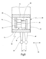
- Fig. 7 shows a coordinate measuring machine 46 in an embodiment of the invention.
- the coordinate measuring machine 46 has a measuring surface 48 on which the measuring object 12 is arranged.
- a portal 50 is movably mounted in a Y-direction.
- a carriage 52 is movably mounted in an X direction.
- a quill 54 is displaceably mounted in the carriage 52 in the Z direction.
- a probe 60 At one end of the quill 54 is a probe 60, which receives the stylus 18 with the Tastkugel 20 in it.
- the stylus 18 can be approached in any direction to the measurement object 12 and the measurement object 12 are touched with the Tastkugel 20.
- scales 56, 57, 58 are provided, along which the portal 50, the carriage 52 and the sleeve 54 are moved.
- the position of the portal 50, the carriage 52 and the sleeve 54 can be determined on the basis of the scales 56, 57, 58.
- the probe 60 has a further sensor (not shown), which can be designed active or passive measuring. By means of this sensor, a deflection of the stylus 18 relative to the probe 60 and the sleeve 54 can be determined, so that a position of the Tastkugel 20 is known.
- the coordinate measuring machine 46 further comprises a control device 64, which may be formed, for example, as a conventional computer.
- the control device 64 then an output device 66 and an input device 67, so that a user at the Output device 66 Read results from surveys or, for example, start a sequence program for a measuring process.
- the input device 67 for example, various modifications with regard to the speed of the measuring process, the surfaces to be touched, etc., can be made.
- the control device 64 is capable of measuring the measurement object 12 according to the method described above. Based on the target surface 13 to be measured, the controller 64 is capable of automatically arranging virtual surfaces 22 accordingly, for example, by spacing virtual surfaces to some extent and placing them parallel to the actual target surface 13 to be measured. For example, it can be provided that, in the case of a spherical surface to be measured, a virtual spherical surface of a somewhat smaller radius with the same center is automatically arranged in order to prevent the stylus from falling into a depression of the spherical surface to be measured. Falling into a depression can thus also take place without knowledge of actually existing depressions or grooves.
- an operating device 69 may also be provided in order to carry out a measuring procedure manually.
- a certain measurement process can be taught or in the event of a failure of the control device 64, the control of the coordinate measuring machine 46 can be taken over manually.
- the control device 64 as shown, have a cable connection to the other elements of the coordinate measuring machine 46, but it can also be connected wirelessly. Of course, it can also be provided that the control device 64 is an integral part of the remaining elements, for example, in the measuring surface 48 or in the portal 50 is arranged. There, the output device 66 or the input device 67 may be arranged.
- Fig. 8 shows on the basis of a simplified schematic representation of the basic operation of the probe 60.
- the probe 60 is designed as an active probe.
- the probe 60 has a fixed part 72 and a movable part 74, which are connected to each other via two leaf springs 42, 44.
- the leaf springs 76, 78 form a spring parallelogram, which allows movement of the part 74 in the direction of the arrow 80.
- the stylus 18 can be deflected by a distance T from its rest position.
- the probe 60 is shown schematically in the deflected position.
- the deflection of the stylus 18 relative to the fixed part 72 may be the result of a probing of the measuring object 12.
- the deflection of the stylus 18 is taken into account in the determination of the spatial coordinates of the Tastkugel 20.
- the deflection of the stylus 18 can be generated at an active probe 60 with the aid of a measuring force generator.
- a leg 82, 84 is arranged on the fixed part 72 and on the movable part 74 in each case.
- the legs 82, 84 are parallel to the leaf springs 76, 78 and parallel to each other.
- a sensor 86 shown here with a scale 88
- a measuring force generator or measuring force transducer 90 is arranged between the legs 82, 84.
- the sensor 86 can be a plunger coil, a Hall sensor, a piezoresistive sensor or another sensor, with the aid of which the spatial deflection of the stylus 18 relative to the fixed part 72 can be determined.
- the measuring force generator 90 may be, for example, a plunger coil, by means of which the two legs 82, 84 can be pulled against each other or pushed apart.
- the probe 60 is also connected to the control device 64, so that they can read on the one hand sizes such as the deflection and the probing force and on the other hand can control the measuring force generator 90.
- Fig. 8 allows the probe 60 only a deflection of the stylus 18 in the direction of arrow 46.
- a probe 60 typically allows a corresponding deflection in two other orthogonal directions in space.
- An embodiment of such a probe 60 is for example in the document DE 44 24 225 A1 described.
- the invention is not limited to this particular probe 60 and may be implemented with other sensing or sensing probes of other sensing systems, particularly passive probes.
- a probe 60 or sensor head of in Fig. 8 in a highly simplified manner, as a rule, has a receptacle on which the stylus 18 or another sensor is interchangeably attached.
Landscapes
- Engineering & Computer Science (AREA)
- Human Computer Interaction (AREA)
- Manufacturing & Machinery (AREA)
- Physics & Mathematics (AREA)
- General Physics & Mathematics (AREA)
- Automation & Control Theory (AREA)
- A Measuring Device Byusing Mechanical Method (AREA)
- Length Measuring Devices With Unspecified Measuring Means (AREA)
- Machine Tool Sensing Apparatuses (AREA)
Claims (15)
- Procédé (10) de régulation d'une opération de mesure par un appareil (46) de mesure de coordonnées qui mesure un objet (12) à mesurer,
l'appareil (46) de mesure de coordonnées présentant un dispositif de régulation (64) ainsi qu'une tête de palpage (60) dotée d'une tige de palpage (18),
un déplacement relatif entre la tige de palpage (18) et une surface (14) de l'objet de mesure (12) étant régulé par le dispositif de régulation (64),
caractérisé en ce que
la surface (14) présente au moins une partie réelle (24) qui correspond à une surface (13) de l'objet à mesurer et au moins une partie virtuelle (26) formée par au moins une surface virtuelle (22),
en ce que le processus de régulation tient compte de surfaces virtuelles (22) non effectivement présentes sur l'objet (12) à mesurer et
en ce que lorsque la tige de palpage (18) aboutit sur cette surface virtuelle (22), des grandeurs de régulation et de mesure sont formées par le dispositif de régulation (64) et la position de la tête de palpage (60) est régulée comme si la surface virtuelle (22) était une surface effective. - Procédé selon la revendication 1, caractérisé en ce que la ou les surfaces virtuelles (22) sont configurées comme vecteurs (23) dont la valeur et la direction sont associées à une coordonnée spatiale définie respective.
- Procédé selon les revendications 1 ou 2, caractérisé en ce que la tête de palpage (60) est une tête de palpage (60) à mesure active et en ce que le dispositif de régulation (64) régule la force de mesure (F) de la tige de palpage, une force de réaction appliquée sur un capteur (90) de force de mesure de la tête de palpage (60) à mesure active étant proportionnelle à la profondeur d'enfoncement de la tige de palpage (18) dans la ou les parties virtuelles (26).
- Procédé selon les revendications 1 ou 2, caractérisé en ce que la tête de palpage (60) est une tête de palpage (60) à mesure passive et en ce que le dispositif de régulation (64) régule la déviation de la tige de palpage (18) et en ce qu'une déviation virtuelle est appliquée sur une déviation de consigne de la tige de palpage (18) proportionnellement à la profondeur d'enfoncement (D) de la tige de palpage (18) dans la ou les parties virtuelles (26).
- Procédé selon la revendication 4, caractérisé en ce que la déviation virtuelle est orientée dans le sens opposé à la déviation de consigne de telle sorte qu'à une profondeur d'enfoncement (D) définie de la tige de palpage (18) dans la ou les parties virtuelles (26), il s'établisse un équilibre entre la déviation de consigne et la déviation virtuelle.
- Procédé selon l'une des revendications 1 à 5, caractérisé en ce que le décalage de position d'une géométrie de consigne connue de l'objet (12) à mesurer est détecté pendant l'opération de mesure le long de la ou des parties réelles (24) et en ce que l'agencement de la ou des parties virtuelles (26) est adapté à l'aide du décalage de position.
- Procédé selon l'une des revendications 1 à 6, caractérisé en ce que la forme géométrique de la surface virtuelle (22) correspond à un plan, à un cylindre ou à une sphère.
- Appareil (46) de mesure de coordonnées qui mesure un objet (12) à mesurer et doté d'un dispositif de régulation (64) et d'une tête de palpage (60) qui présente une tige de palpage (18),
un déplacement relatif entre la tige de palpage (18) et une surface (14) de l'objet de mesure (12) étant régulé par le dispositif de régulation (64),
caractérisé en ce que
la surface (14) présente au moins une partie réelle (24) qui correspond à une surface (13) de l'objet à mesurer et au moins une partie virtuelle (26) formée par au moins une surface virtuelle (22), en ce que le processus de régulation tient compte de surfaces virtuelles (22) non effectivement présentes sur l'objet (12) à mesurer et en ce que lorsque la tige de palpage (18) aboutit sur cette surface virtuelle (22), des grandeurs de régulation et de mesure sont formées par le dispositif de régulation (64) et la position de la tête de palpage (60) est régulée comme si la surface virtuelle (22) était une surface effective. - Appareil de mesure de coordonnées selon la revendication 8, caractérisé en ce que la ou les surfaces virtuelles (22) sont configurées comme vecteurs (23) dont la valeur et la direction sont associées à une coordonnée spatiale définie respective.
- Appareil de mesure de coordonnées selon les revendications 8 ou 9, caractérisé en ce que la tête de palpage (60) est une tête de palpage (60) à mesure active et en ce que le dispositif de régulation (64) régule la force de mesure de la tige de palpage (18), une force de réaction appliquée sur un capteur (90) de force de mesure de la tête de palpage (60) à mesure active étant proportionnelle à la profondeur d'enfoncement (X) de la tige de palpage (18) dans la ou les parties virtuelles.
- Appareil de mesure de coordonnées selon les revendications 8 ou 9, caractérisé en ce que la tête de palpage (60) est une tête de palpage (60) à mesure passive et en ce que le dispositif de régulation (64) régule la déviation de la tige de palpage (18) et en ce qu'une déviation virtuelle est appliquée sur une déviation de consigne de la tige de palpage (18) proportionnellement à la profondeur d'enfoncement de la tige de palpage (18) dans la ou les parties virtuelles.
- Appareil de mesure de coordonnées selon la revendication 11, caractérisé en ce que la déviation virtuelle est orientée dans le sens opposé à la déviation de consigne de telle sorte qu'à une profondeur d'enfoncement (D) définie de la tige de palpage (18) dans la ou les parties virtuelles (26), il s'établisse un équilibre entre la déviation de consigne et la déviation virtuelle.
- Appareil de mesure de coordonnées selon les revendications 8 à 12, caractérisé en ce que le décalage de position d'une géométrie de consigne connue de l'objet (12) à mesurer est détecté pendant l'opération de mesure le long de la ou des parties réelles (24) et en ce que l'agencement de la ou des parties virtuelles (26) est adapté à l'aide du décalage de position.
- Appareil de mesure de coordonnées selon les revendications 8 à 13, caractérisé en ce que la forme géométrique de la surface virtuelle (22) correspond à un plan, à un cylindre ou à une sphère.
- Programme informatique doté de moyens de code de programme et configuré pour mettre en ouvre toutes les étapes d'un procédé (10) selon l'une des revendications 1 à 7 lorsque le programme informatique est exécuté dans un appareil (46) de mesure de coordonnées.
Priority Applications (1)
| Application Number | Priority Date | Filing Date | Title |
|---|---|---|---|
| EP14164249.6A EP2755095B1 (fr) | 2010-02-15 | 2011-02-09 | Procédé de régulation d'un procédé de mesure au moyen de surfaces virtuelles |
Applications Claiming Priority (3)
| Application Number | Priority Date | Filing Date | Title |
|---|---|---|---|
| DE102010008751A DE102010008751A1 (de) | 2010-02-15 | 2010-02-15 | Verfahren zum Regeln eines Messvorgangs mittels virtueller Oberflächen |
| DE102010012974 | 2010-03-23 | ||
| PCT/EP2011/051895 WO2011098487A1 (fr) | 2010-02-15 | 2011-02-09 | Procédé pour le réglage d'un processus de mesure au moyen de surfaces virtuelles |
Related Child Applications (2)
| Application Number | Title | Priority Date | Filing Date |
|---|---|---|---|
| EP14164249.6A Division EP2755095B1 (fr) | 2010-02-15 | 2011-02-09 | Procédé de régulation d'un procédé de mesure au moyen de surfaces virtuelles |
| EP14164249.6A Division-Into EP2755095B1 (fr) | 2010-02-15 | 2011-02-09 | Procédé de régulation d'un procédé de mesure au moyen de surfaces virtuelles |
Publications (2)
| Publication Number | Publication Date |
|---|---|
| EP2537074A1 EP2537074A1 (fr) | 2012-12-26 |
| EP2537074B1 true EP2537074B1 (fr) | 2014-05-28 |
Family
ID=43805694
Family Applications (2)
| Application Number | Title | Priority Date | Filing Date |
|---|---|---|---|
| EP11705482.5A Active EP2537074B1 (fr) | 2010-02-15 | 2011-02-09 | Procédé pour le régulation d'un processus de mesure au moyen de surfaces virtuelles |
| EP14164249.6A Active EP2755095B1 (fr) | 2010-02-15 | 2011-02-09 | Procédé de régulation d'un procédé de mesure au moyen de surfaces virtuelles |
Family Applications After (1)
| Application Number | Title | Priority Date | Filing Date |
|---|---|---|---|
| EP14164249.6A Active EP2755095B1 (fr) | 2010-02-15 | 2011-02-09 | Procédé de régulation d'un procédé de mesure au moyen de surfaces virtuelles |
Country Status (5)
| Country | Link |
|---|---|
| US (1) | US8745886B2 (fr) |
| EP (2) | EP2537074B1 (fr) |
| JP (2) | JP5934115B2 (fr) |
| CN (1) | CN102906651B (fr) |
| WO (1) | WO2011098487A1 (fr) |
Families Citing this family (7)
| Publication number | Priority date | Publication date | Assignee | Title |
|---|---|---|---|---|
| JP5934115B2 (ja) * | 2010-02-15 | 2016-06-15 | カール ザイス インダストリエル メステクニーク ゲゼルシャフト ミット ベシュレンクテル ハフツング | 仮想表面によって測定過程を制御する方法 |
| ES2747383T3 (es) * | 2014-02-27 | 2020-03-10 | Fidia Spa | Método y sistema para verificar la precisión de posicionamiento de una máquina CNC |
| CN104308663A (zh) * | 2014-10-27 | 2015-01-28 | 湘潭大学 | 一种弧面凸轮廓面加工误差虚拟测量的方法 |
| US10254113B2 (en) * | 2015-05-04 | 2019-04-09 | Mitutoyo Corporation | Inspection program editing environment providing user defined collision avoidance volumes |
| US11073382B2 (en) * | 2015-11-13 | 2021-07-27 | Hexagon Technology Center Gmbh | Error compensation for coordinate measuring machines using a reference module |
| WO2018201337A1 (fr) * | 2017-05-03 | 2018-11-08 | 大连理工大学 | Système in situ pour mesurer une erreur de forme dans une grande surface annulaire |
| GB2562489B (en) | 2017-05-16 | 2022-06-22 | Skf Aerospace France | Method of determining wear in a bearing surface |
Family Cites Families (22)
| Publication number | Priority date | Publication date | Assignee | Title |
|---|---|---|---|---|
| JP2758810B2 (ja) * | 1992-10-15 | 1998-05-28 | 株式会社ミツトヨ | 形状測定方法 |
| DE4326551C2 (de) * | 1993-08-07 | 1997-04-17 | Heidenhain Gmbh Dr Johannes | Kalibrier-Verfahren zum Ermitteln und Kompensieren unterschiedlicher Antastkraft-Verhältnisse bei Mehrkoordinaten-Tastsystemen |
| DE4336863C2 (de) * | 1993-10-28 | 1998-01-22 | Zeiss Carl Fa | Verfahren zur Steuerung von Koordinatenmeßgeräten |
| DE4424225A1 (de) | 1994-07-09 | 1996-01-11 | Zeiss Carl Fa | Tastkopf für Koordinatenmeßgeräte |
| DE19529574A1 (de) * | 1995-08-11 | 1997-02-13 | Zeiss Carl Fa | Koordinatenmeßgerät mit einer Steuerung, die den Tastkopf des Meßgeräts nach Solldaten verfährt |
| EP0849653B1 (fr) * | 1996-12-21 | 2004-04-28 | Carl Zeiss | Méthode de commande d'un dispositif de mesure de coordonnées et dispositif de mesure de coordonnées |
| DE19805155B4 (de) * | 1998-02-10 | 2007-09-27 | Mycrona Gesellschaft für innovative Messtechnik mbH | Verfahren zum Erzeugen von Steuerdaten für Koordinatenmeßgeräte |
| JP2001330428A (ja) * | 2000-05-23 | 2001-11-30 | Natl Inst Of Advanced Industrial Science & Technology Meti | 3次元測定機の測定誤差評価方法及び3次元測定機用ゲージ |
| US7693325B2 (en) * | 2004-01-14 | 2010-04-06 | Hexagon Metrology, Inc. | Transprojection of geometry data |
| JP2005257420A (ja) * | 2004-03-11 | 2005-09-22 | Sii Nanotechnology Inc | 走査型プローブ顕微鏡 |
| GB0508217D0 (en) * | 2005-04-25 | 2005-06-01 | Renishaw Plc | Method for scanning the surface of a workpiece |
| KR100660415B1 (ko) * | 2005-06-07 | 2006-12-22 | 주식회사 아이너스기술 | 허용 오차 영역을 이용한 3차원 측정 데이터의 검출 방법 |
| US7805854B2 (en) * | 2006-05-15 | 2010-10-05 | Hexagon Metrology, Inc. | Systems and methods for positioning and measuring objects using a CMM |
| GB0625260D0 (en) * | 2006-12-19 | 2007-01-24 | Renishaw Plc | A method for measuring a workpiece using a machine tool |
| GB0712008D0 (en) * | 2007-06-21 | 2007-08-01 | Renishaw Plc | Apparatus and method of calibration |
| GB0716218D0 (en) * | 2007-08-20 | 2007-09-26 | Renishaw Plc | Measurement path generation |
| CN101871775B (zh) * | 2009-04-21 | 2012-09-19 | 鸿富锦精密工业(深圳)有限公司 | 三坐标测量机编程系统及方法 |
| JP5371532B2 (ja) * | 2009-04-23 | 2013-12-18 | 株式会社ミツトヨ | 三次元測定機 |
| JP5269698B2 (ja) * | 2009-06-10 | 2013-08-21 | 株式会社ミツトヨ | 真円度測定装置 |
| JP5934115B2 (ja) * | 2010-02-15 | 2016-06-15 | カール ザイス インダストリエル メステクニーク ゲゼルシャフト ミット ベシュレンクテル ハフツング | 仮想表面によって測定過程を制御する方法 |
| US8701298B2 (en) * | 2011-06-01 | 2014-04-22 | Tesa Sa | Coordinate measuring machine |
| US8756792B2 (en) * | 2011-06-08 | 2014-06-24 | The Boeing Company | Digitally designed shims for joining parts of an assembly |
-
2011
- 2011-02-09 JP JP2012552381A patent/JP5934115B2/ja active Active
- 2011-02-09 CN CN201180009762.2A patent/CN102906651B/zh active Active
- 2011-02-09 WO PCT/EP2011/051895 patent/WO2011098487A1/fr active Application Filing
- 2011-02-09 EP EP11705482.5A patent/EP2537074B1/fr active Active
- 2011-02-09 EP EP14164249.6A patent/EP2755095B1/fr active Active
-
2012
- 2012-08-13 US US13/572,967 patent/US8745886B2/en active Active
-
2016
- 2016-01-15 JP JP2016006002A patent/JP2016105101A/ja active Pending
Also Published As
| Publication number | Publication date |
|---|---|
| CN102906651A (zh) | 2013-01-30 |
| WO2011098487A1 (fr) | 2011-08-18 |
| EP2537074A1 (fr) | 2012-12-26 |
| US20130036619A1 (en) | 2013-02-14 |
| EP2755095A1 (fr) | 2014-07-16 |
| US8745886B2 (en) | 2014-06-10 |
| JP5934115B2 (ja) | 2016-06-15 |
| JP2013519870A (ja) | 2013-05-30 |
| CN102906651B (zh) | 2015-01-28 |
| JP2016105101A (ja) | 2016-06-09 |
| EP2755095B1 (fr) | 2016-04-20 |
Similar Documents
| Publication | Publication Date | Title |
|---|---|---|
| EP2537074B1 (fr) | Procédé pour le régulation d'un processus de mesure au moyen de surfaces virtuelles | |
| EP3286524B1 (fr) | Procédé et dispositif permettant de déterminer les propriétés dimensionnelles effectives d'un objet à mesurer | |
| EP2010864B1 (fr) | Scannerisation d'une surface avec un appareil de mesure de coordonnees | |
| DE102013219389A1 (de) | Reduzierung von Fehlern einer Drehvorrichtung, die bei der Bestimmung von Koordinaten eines Werkstücks oder bei der Bearbeitung eines Werkstücks verwendet wird | |
| DE102014112396B4 (de) | Verfahren zur Einzelpunktantastung eines Werkstücks und Koordinatenmessgerät | |
| EP3359913B1 (fr) | Surveillance d'un paramètre de sécurité d'un appareil de mesure de coordonnées | |
| EP2561311B1 (fr) | Operation d'une machine de mesure de coordonnées ou d'une machine outil | |
| EP3228974B1 (fr) | Capteur de rugosite , dispositif dote d'un capteur de rugosite et procede correspondant | |
| EP3255373B1 (fr) | Mesure de contact au niveau du flanc d'une dent d'une roue dentée | |
| DE102010008751A1 (de) | Verfahren zum Regeln eines Messvorgangs mittels virtueller Oberflächen | |
| DE102013101931B4 (de) | Verfahren und Vorrichtung zum Vermessen eines Werkstücks | |
| DE102015205566A1 (de) | Kalibrierung eines an einem beweglichen Teil eines Koordinatenmessgeräts angebrachten taktilen Tasters | |
| EP1893941B1 (fr) | Procede et dispositif pour determiner des parametres geometriques d'un objet de mesure conique | |
| DE102010011841B4 (de) | Verfahren zur Validierung eines Messergebnisses eines Koordinatenmessgeräts | |
| EP3537102B1 (fr) | Procédé et dispositif d'augmentation du rendement pour une précision suffisante lors de la mesure de pièces à usiner | |
| EP2378239A2 (fr) | Dispositif de mesure d'objets | |
| EP2378240A2 (fr) | Dispositif de mesure d'objets | |
| DE102013210739B3 (de) | Koordinatenmessgerät und Verfahren zur Vermessung eines Werkstücks mit einer selbstfahrenden Antriebseinheit und einer fahrbaren Messeinheit | |
| DE102013207116B4 (de) | Koordinatenmessgerät und Verfahren zur Steuerung eines Koordinatenmessgeräts | |
| DE102010006505A1 (de) | Koordinatenmessgerät mit passivem Dreh-Schwenk-Mechanismus | |
| DE102010018493B4 (de) | Koordinatenmessgerät zum Bestimmen von Raumkoordinaten an einem Messobjekt sowie Tastkopf für ein solches Koordinatenmessgerät | |
| DE102017108033A1 (de) | Verfahren zur Messung von Koordinaten oder Eigenschaften einer Werkstückoberfläche | |
| DE102009034938B4 (de) | Verfahren zur Kommandierung eines Bewegungssystems mit einer Messeinrichtung | |
| DE102014102261A1 (de) | Vorrichtung und Verfahren zur Vermessung von Messobjekten | |
| DE102019220060A1 (de) | Verfahren zum Kalibrieren eines taktilen Sensors |
Legal Events
| Date | Code | Title | Description |
|---|---|---|---|
| PUAI | Public reference made under article 153(3) epc to a published international application that has entered the european phase |
Free format text: ORIGINAL CODE: 0009012 |
|
| 17P | Request for examination filed |
Effective date: 20120914 |
|
| AK | Designated contracting states |
Kind code of ref document: A1 Designated state(s): AL AT BE BG CH CY CZ DE DK EE ES FI FR GB GR HR HU IE IS IT LI LT LU LV MC MK MT NL NO PL PT RO RS SE SI SK SM TR |
|
| DAX | Request for extension of the european patent (deleted) | ||
| GRAP | Despatch of communication of intention to grant a patent |
Free format text: ORIGINAL CODE: EPIDOSNIGR1 |
|
| INTG | Intention to grant announced |
Effective date: 20131204 |
|
| GRAS | Grant fee paid |
Free format text: ORIGINAL CODE: EPIDOSNIGR3 |
|
| GRAA | (expected) grant |
Free format text: ORIGINAL CODE: 0009210 |
|
| AK | Designated contracting states |
Kind code of ref document: B1 Designated state(s): AL AT BE BG CH CY CZ DE DK EE ES FI FR GB GR HR HU IE IS IT LI LT LU LV MC MK MT NL NO PL PT RO RS SE SI SK SM TR |
|
| REG | Reference to a national code |
Ref country code: GB Ref legal event code: FG4D Free format text: NOT ENGLISH |
|
| REG | Reference to a national code |
Ref country code: CH Ref legal event code: EP |
|
| REG | Reference to a national code |
Ref country code: AT Ref legal event code: REF Ref document number: 670403 Country of ref document: AT Kind code of ref document: T Effective date: 20140615 |
|
| REG | Reference to a national code |
Ref country code: IE Ref legal event code: FG4D Free format text: LANGUAGE OF EP DOCUMENT: GERMAN |
|
| REG | Reference to a national code |
Ref country code: DE Ref legal event code: R096 Ref document number: 502011003233 Country of ref document: DE Effective date: 20140710 |
|
| REG | Reference to a national code |
Ref country code: NL Ref legal event code: VDEP Effective date: 20140528 |
|
| REG | Reference to a national code |
Ref country code: LT Ref legal event code: MG4D |
|
| PG25 | Lapsed in a contracting state [announced via postgrant information from national office to epo] |
Ref country code: GR Free format text: LAPSE BECAUSE OF FAILURE TO SUBMIT A TRANSLATION OF THE DESCRIPTION OR TO PAY THE FEE WITHIN THE PRESCRIBED TIME-LIMIT Effective date: 20140829 Ref country code: LT Free format text: LAPSE BECAUSE OF FAILURE TO SUBMIT A TRANSLATION OF THE DESCRIPTION OR TO PAY THE FEE WITHIN THE PRESCRIBED TIME-LIMIT Effective date: 20140528 Ref country code: FI Free format text: LAPSE BECAUSE OF FAILURE TO SUBMIT A TRANSLATION OF THE DESCRIPTION OR TO PAY THE FEE WITHIN THE PRESCRIBED TIME-LIMIT Effective date: 20140528 Ref country code: CY Free format text: LAPSE BECAUSE OF FAILURE TO SUBMIT A TRANSLATION OF THE DESCRIPTION OR TO PAY THE FEE WITHIN THE PRESCRIBED TIME-LIMIT Effective date: 20140528 Ref country code: NO Free format text: LAPSE BECAUSE OF FAILURE TO SUBMIT A TRANSLATION OF THE DESCRIPTION OR TO PAY THE FEE WITHIN THE PRESCRIBED TIME-LIMIT Effective date: 20140828 |
|
| PG25 | Lapsed in a contracting state [announced via postgrant information from national office to epo] |
Ref country code: HR Free format text: LAPSE BECAUSE OF FAILURE TO SUBMIT A TRANSLATION OF THE DESCRIPTION OR TO PAY THE FEE WITHIN THE PRESCRIBED TIME-LIMIT Effective date: 20140528 Ref country code: RS Free format text: LAPSE BECAUSE OF FAILURE TO SUBMIT A TRANSLATION OF THE DESCRIPTION OR TO PAY THE FEE WITHIN THE PRESCRIBED TIME-LIMIT Effective date: 20140528 Ref country code: LV Free format text: LAPSE BECAUSE OF FAILURE TO SUBMIT A TRANSLATION OF THE DESCRIPTION OR TO PAY THE FEE WITHIN THE PRESCRIBED TIME-LIMIT Effective date: 20140528 Ref country code: SE Free format text: LAPSE BECAUSE OF FAILURE TO SUBMIT A TRANSLATION OF THE DESCRIPTION OR TO PAY THE FEE WITHIN THE PRESCRIBED TIME-LIMIT Effective date: 20140528 |
|
| PG25 | Lapsed in a contracting state [announced via postgrant information from national office to epo] |
Ref country code: PT Free format text: LAPSE BECAUSE OF FAILURE TO SUBMIT A TRANSLATION OF THE DESCRIPTION OR TO PAY THE FEE WITHIN THE PRESCRIBED TIME-LIMIT Effective date: 20140929 |
|
| PG25 | Lapsed in a contracting state [announced via postgrant information from national office to epo] |
Ref country code: CZ Free format text: LAPSE BECAUSE OF FAILURE TO SUBMIT A TRANSLATION OF THE DESCRIPTION OR TO PAY THE FEE WITHIN THE PRESCRIBED TIME-LIMIT Effective date: 20140528 Ref country code: EE Free format text: LAPSE BECAUSE OF FAILURE TO SUBMIT A TRANSLATION OF THE DESCRIPTION OR TO PAY THE FEE WITHIN THE PRESCRIBED TIME-LIMIT Effective date: 20140528 Ref country code: DK Free format text: LAPSE BECAUSE OF FAILURE TO SUBMIT A TRANSLATION OF THE DESCRIPTION OR TO PAY THE FEE WITHIN THE PRESCRIBED TIME-LIMIT Effective date: 20140528 Ref country code: SK Free format text: LAPSE BECAUSE OF FAILURE TO SUBMIT A TRANSLATION OF THE DESCRIPTION OR TO PAY THE FEE WITHIN THE PRESCRIBED TIME-LIMIT Effective date: 20140528 Ref country code: ES Free format text: LAPSE BECAUSE OF FAILURE TO SUBMIT A TRANSLATION OF THE DESCRIPTION OR TO PAY THE FEE WITHIN THE PRESCRIBED TIME-LIMIT Effective date: 20140528 Ref country code: RO Free format text: LAPSE BECAUSE OF FAILURE TO SUBMIT A TRANSLATION OF THE DESCRIPTION OR TO PAY THE FEE WITHIN THE PRESCRIBED TIME-LIMIT Effective date: 20140528 |
|
| PG25 | Lapsed in a contracting state [announced via postgrant information from national office to epo] |
Ref country code: NL Free format text: LAPSE BECAUSE OF FAILURE TO SUBMIT A TRANSLATION OF THE DESCRIPTION OR TO PAY THE FEE WITHIN THE PRESCRIBED TIME-LIMIT Effective date: 20140528 Ref country code: PL Free format text: LAPSE BECAUSE OF FAILURE TO SUBMIT A TRANSLATION OF THE DESCRIPTION OR TO PAY THE FEE WITHIN THE PRESCRIBED TIME-LIMIT Effective date: 20140528 |
|
| REG | Reference to a national code |
Ref country code: DE Ref legal event code: R097 Ref document number: 502011003233 Country of ref document: DE |
|
| PLBE | No opposition filed within time limit |
Free format text: ORIGINAL CODE: 0009261 |
|
| STAA | Information on the status of an ep patent application or granted ep patent |
Free format text: STATUS: NO OPPOSITION FILED WITHIN TIME LIMIT |
|
| 26N | No opposition filed |
Effective date: 20150303 |
|
| REG | Reference to a national code |
Ref country code: DE Ref legal event code: R097 Ref document number: 502011003233 Country of ref document: DE Effective date: 20150303 |
|
| PG25 | Lapsed in a contracting state [announced via postgrant information from national office to epo] |
Ref country code: BE Free format text: LAPSE BECAUSE OF NON-PAYMENT OF DUE FEES Effective date: 20150228 |
|
| PG25 | Lapsed in a contracting state [announced via postgrant information from national office to epo] |
Ref country code: SI Free format text: LAPSE BECAUSE OF FAILURE TO SUBMIT A TRANSLATION OF THE DESCRIPTION OR TO PAY THE FEE WITHIN THE PRESCRIBED TIME-LIMIT Effective date: 20140528 |
|
| PG25 | Lapsed in a contracting state [announced via postgrant information from national office to epo] |
Ref country code: LU Free format text: LAPSE BECAUSE OF FAILURE TO SUBMIT A TRANSLATION OF THE DESCRIPTION OR TO PAY THE FEE WITHIN THE PRESCRIBED TIME-LIMIT Effective date: 20150209 |
|
| REG | Reference to a national code |
Ref country code: CH Ref legal event code: PL |
|
| PG25 | Lapsed in a contracting state [announced via postgrant information from national office to epo] |
Ref country code: MC Free format text: LAPSE BECAUSE OF FAILURE TO SUBMIT A TRANSLATION OF THE DESCRIPTION OR TO PAY THE FEE WITHIN THE PRESCRIBED TIME-LIMIT Effective date: 20140528 Ref country code: LI Free format text: LAPSE BECAUSE OF NON-PAYMENT OF DUE FEES Effective date: 20150228 Ref country code: CH Free format text: LAPSE BECAUSE OF NON-PAYMENT OF DUE FEES Effective date: 20150228 |
|
| REG | Reference to a national code |
Ref country code: IE Ref legal event code: MM4A |
|
| REG | Reference to a national code |
Ref country code: FR Ref legal event code: ST Effective date: 20151030 |
|
| PG25 | Lapsed in a contracting state [announced via postgrant information from national office to epo] |
Ref country code: IE Free format text: LAPSE BECAUSE OF NON-PAYMENT OF DUE FEES Effective date: 20150209 |
|
| PG25 | Lapsed in a contracting state [announced via postgrant information from national office to epo] |
Ref country code: FR Free format text: LAPSE BECAUSE OF NON-PAYMENT OF DUE FEES Effective date: 20150302 |
|
| PG25 | Lapsed in a contracting state [announced via postgrant information from national office to epo] |
Ref country code: IS Free format text: LAPSE BECAUSE OF FAILURE TO SUBMIT A TRANSLATION OF THE DESCRIPTION OR TO PAY THE FEE WITHIN THE PRESCRIBED TIME-LIMIT Effective date: 20140528 |
|
| PG25 | Lapsed in a contracting state [announced via postgrant information from national office to epo] |
Ref country code: MT Free format text: LAPSE BECAUSE OF FAILURE TO SUBMIT A TRANSLATION OF THE DESCRIPTION OR TO PAY THE FEE WITHIN THE PRESCRIBED TIME-LIMIT Effective date: 20140528 |
|
| REG | Reference to a national code |
Ref country code: AT Ref legal event code: MM01 Ref document number: 670403 Country of ref document: AT Kind code of ref document: T Effective date: 20160209 |
|
| PG25 | Lapsed in a contracting state [announced via postgrant information from national office to epo] |
Ref country code: HU Free format text: LAPSE BECAUSE OF FAILURE TO SUBMIT A TRANSLATION OF THE DESCRIPTION OR TO PAY THE FEE WITHIN THE PRESCRIBED TIME-LIMIT; INVALID AB INITIO Effective date: 20110209 Ref country code: SM Free format text: LAPSE BECAUSE OF FAILURE TO SUBMIT A TRANSLATION OF THE DESCRIPTION OR TO PAY THE FEE WITHIN THE PRESCRIBED TIME-LIMIT Effective date: 20140528 Ref country code: BG Free format text: LAPSE BECAUSE OF FAILURE TO SUBMIT A TRANSLATION OF THE DESCRIPTION OR TO PAY THE FEE WITHIN THE PRESCRIBED TIME-LIMIT Effective date: 20140528 Ref country code: AT Free format text: LAPSE BECAUSE OF NON-PAYMENT OF DUE FEES Effective date: 20160209 |
|
| PG25 | Lapsed in a contracting state [announced via postgrant information from national office to epo] |
Ref country code: TR Free format text: LAPSE BECAUSE OF FAILURE TO SUBMIT A TRANSLATION OF THE DESCRIPTION OR TO PAY THE FEE WITHIN THE PRESCRIBED TIME-LIMIT Effective date: 20140528 |
|
| PG25 | Lapsed in a contracting state [announced via postgrant information from national office to epo] |
Ref country code: MK Free format text: LAPSE BECAUSE OF FAILURE TO SUBMIT A TRANSLATION OF THE DESCRIPTION OR TO PAY THE FEE WITHIN THE PRESCRIBED TIME-LIMIT Effective date: 20140528 |
|
| PG25 | Lapsed in a contracting state [announced via postgrant information from national office to epo] |
Ref country code: AL Free format text: LAPSE BECAUSE OF FAILURE TO SUBMIT A TRANSLATION OF THE DESCRIPTION OR TO PAY THE FEE WITHIN THE PRESCRIBED TIME-LIMIT Effective date: 20140528 |
|
| PGFP | Annual fee paid to national office [announced via postgrant information from national office to epo] |
Ref country code: IT Payment date: 20230223 Year of fee payment: 13 |
|
| P01 | Opt-out of the competence of the unified patent court (upc) registered |
Effective date: 20230525 |
|
| PGFP | Annual fee paid to national office [announced via postgrant information from national office to epo] |
Ref country code: DE Payment date: 20240219 Year of fee payment: 14 Ref country code: GB Payment date: 20240219 Year of fee payment: 14 |