EP2536008B1 - Procédé et dispositif d'enroulement de demi-coques de stator - Google Patents
Procédé et dispositif d'enroulement de demi-coques de stator Download PDFInfo
- Publication number
- EP2536008B1 EP2536008B1 EP12003607.4A EP12003607A EP2536008B1 EP 2536008 B1 EP2536008 B1 EP 2536008B1 EP 12003607 A EP12003607 A EP 12003607A EP 2536008 B1 EP2536008 B1 EP 2536008B1
- Authority
- EP
- European Patent Office
- Prior art keywords
- tool
- stator
- wire
- winding
- half shell
- Prior art date
- Legal status (The legal status is an assumption and is not a legal conclusion. Google has not performed a legal analysis and makes no representation as to the accuracy of the status listed.)
- Not-in-force
Links
Images


Classifications
-
- H—ELECTRICITY
- H02—GENERATION; CONVERSION OR DISTRIBUTION OF ELECTRIC POWER
- H02K—DYNAMO-ELECTRIC MACHINES
- H02K15/00—Methods or apparatus specially adapted for manufacturing, assembling, maintaining or repairing of dynamo-electric machines
- H02K15/08—Forming windings by laying conductors into or around core parts
- H02K15/095—Forming windings by laying conductors into or around core parts by laying conductors around salient poles
Definitions
- the invention relates to a method and a device for the winding of Stator Halbschalen.
- a current way to solve this problem is to first wind the wire into a coil and then insert it into the grooves between pole horns and stator walls.
- the field coils are provided with insulating paper which separates the field coils from the stator half shell, which is regularly designed as a laminated core.
- the paper must be folded in a cumbersome process to the effective strands of the coil and secured, for example, with an adhesive strip.
- the grooves When a fully wound coil is inserted into the grooves, the grooves must be geometrically shaped so that the finished formed coil can be pulled over the pole horns.
- the coil is to be provided with a coating after being introduced into the grooves, for example by electrically heating them in a short circuit process and immersing them in a powder bath, the coil must additionally be kept in shape so that the geometry that is present during the insertion process has been generated, not changed.
- Another way to wind such a stator half-shell is direct winding with a needle winding system.
- plastic insulating parts are used which ensure the insulation between the wire and the stator half shell.
- the disadvantage here is that the resulting winding head does not take the desired semicircular shape in the needle winding process, so that the goal of a compact design of the stator can not be achieved to a sufficient extent.
- the plastic insulating parts worsen the degree of filling of the slot slots and thus the efficiency of the resulting stators.
- the invention is therefore based on the object to provide a method and an apparatus for winding a wire to a coil for a two-pole stator, which do not have the disadvantages mentioned or to a reduced extent.
- a stator half-shell to be wound is received on a receiving tool.
- the outside of the stator half shell points towards the receiving tool.
- An abutment tool engages the inside of the Stator Halbschale, so that the grooves between the pole horns and the stator are accessible through a gap between the receiving tool and the abutment tool.
- a winding tool which preferably rotates about an axis, in particular a so-called flyer, serves to feed the wire.
- the stator half-shell is positioned relative to the axis of rotation of the winding tool such that the longitudinal axis of a stator formed with the stator half-shell would cut the axis of rotation of the winding tool at right angles.
- the axis of rotation passes through the center of gravity of the projection surface of the stator half-shell received on the receiving tool in the direction of the axis of rotation.
- the wire is deflected in the direction of the outside of the stator half-shell accommodated on the receiving tool.
- the abutment tool in the region of at least one winding head of the coil to be generated on a wire deflector.
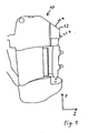
- the wire deflection occurs in the direction of the outside of the recorded on the receiving tool stator half shell out of the contour of the abutment tool. It is important for the geometrical configuration of the wire deflection member to be sufficiently rounded so that the wire passing the deflection member can not be damaged by sharp edges or the like. Furthermore, the deflection element must be designed in this way be that at a suitably selected winding speed, which means in particular at a suitably selected speed of the rotating winding tool, the wire from the winding tool for already finished winding extending wire section to impart a movement impulse toward the outside of the stator half shell, ie in the direction of the picking tool.
- the surfaces oriented in the direction of the longitudinal axis of the stator half-shell i. the surfaces on which the wire slides during winding, are formed such that they form a sloping to the receiving tool down sliding surface.
- the wire section receives a momentum through which the wire, due to its self-inertia, penetrates into the rear portions of the grooves, i. in the stator wall-side areas at the bottom of the groove is conveyed, instead of winding for turn along the pole horns to invest this and can not reach a stator wall-side space region of the groove can.
- the wire section between the winding tool and the already wound to the coil wire section after being deflected by the wire deflection preferably loses contact with the Drahtablenkelement before it assumes its final position in the coil to be wound.
- the wire is guided by the wire deflector not touching in its end position, but only based on the inertia trajectory of the wire is influenced such that it ends in otherwise difficult to reach area of the groove bottom.
- the abutment tool on slide elements with which the wire sections which extend between the pole horns and the stator in the grooves can be pressed in the direction of the receiving tool.
- slide elements exert a pressure on the wire winding in the grooves, so as to allow the desired, parallel to the longitudinal axis of the stator ideal course of the wires and the highest possible Nutaus spallung connected as far as possible.
- the receiving tool has a pressure device for fixing an insulating material in the stator wall.
- the insulating material can be, for example, a paper intended to provide electrical insulation between the windings of the coil and the stator half-shell.
- the insulating material is inserted before winding in the groove between the stator wall and the pole piece.
- the fixation can be carried out by the insulating material is pressed against the stator.
- the pressure occurs in the direction of the outside of the stator half-shell in order to ensure optimum contact of the paper.
- the purpose of this provided on the receiving tool pressure device must be performed for this purpose in a movement in which the pressure device initially embraces the insulating material coming from the outside of Stator Halbschale ago and then presses in a directed to the outside of the stator half-shell towards the insulating material to the stator wall.
- a slotted guide may be provided, which has an angled, in particular an L-shaped contour to effect the change of the direction of movement from gripping to pressing the insulating material.
- the insulation material is fixable not only in the region of the stator wall, but also in the region of the pole horns.
- the fixation is done preferably by the abutment tool, in particular by the insulating material is clamped by this.
- the abutment tool preferably has a clamping device which is arranged in the region of the pole horns of a stator half-shell received on the receiving tool.
- This clamping device is preferably actuated by a mechanism during the attack of the abutment tool on the stator half shell and thereby automatically clamps when moving together of receiving tool and abutment tool, the insulation material.
- the receiving tool has a guide, which is designed in particular as a depression or channel, which is suitable by their positioning on the receiving tool, at the beginning of the winding process, the incoming wire in the tool to the area to be wound between a pole piece and bring the stator wall, or provides a free space for the wire end leading to the coil, so that this wire end can dodge in the winding in this space and is not damaged by the structure of the winding.
- the coil prior to removal of the wound Stator vomschale from the receiving tool, the coil electrically contacted and heated by the application of an electric current, wherein a coating applied to the wire coating is at least partially melted temporarily.
- the wire preferably reaches a temperature which is suitable for melting a preferably thermoplastic coating on the wire at least to the extent that caking of the wires is achieved with one another.
- the coating is in particular a baked enamel, which, upon cooling after baking, still provides sufficient electrical insulation of the individual turns of the Coil ensured with each other.
- the temperature that has to be reached for baking depends on the wire, in particular on the coating of the wire. The temperature is preferably 220 ° C +/- 20 ° C.
- a powder coating can be applied to the coil, wherein preferably the residual heat of a previous heating of the wire, for example, used to bake the individual turns with a baked enamel, is used to selectively apply the powder coating on the wire.
- the wound Stator Halbschale is introduced with the still hot wire in a powder bath, with the result that the powder selectively on the wire, but not on the Stator relishschale adheres and melts, so that the result is a powder coating only the wire.
- the powder coating process preferably takes place at temperatures of about 150 ° C. If the residual heat of the Verbackreaes used, it must take place at a sufficiently high temperature to cause a sufficiently long cooling phase. This is required in order to have sufficient time to remove the wound stator half-shells from the device and to introduce them into the powder bath.
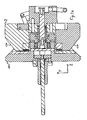
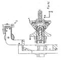
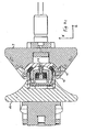
- the exemplary device according to the invention has a receiving tool 2 and an abutment tool 10, which can be moved together in the direction of the axis Z, so that a stator half-shell 1 can be fixed between the tools.
- the exemplary receiving tool according to the invention has a guide 18 for the starting wire of the coil winding and a further guide 19, with which the second wire end can be guided out of the coil, for example, in the other methods can be contacted electrically to allow a caking.
- the receiving tool 2, the pressure device 15. This is designed such that it can embrace the insulating material 9 and press in the direction of the outer side 17 of the stator half-shell 1 to the stator 13. The necessary change in the direction of movement of the pressure device 15 during gripping and subsequent pressing of the insulating material 9 to the stator 13 is thereby made possible by the L-shaped slotted guide 16.
- Sliding elements 20 are provided on the abutment tool 11, which can press the coil 4 into the groove between the stator wall 13 and the pole horns 8 of the stator half-shell 1 accommodated on the receiving tool 2.
- the abutment tool 10 has a clamping device 14, which serves to fix the insulation material 9 in the region of the pole horns 8.
- the rotating winding tool 3 rotates about the rotation axis R, which runs longitudinally parallel to the collapsing direction Z of the receiving tool 2 and counter-bearing tool 10 and perpendicular to the stator axis, which is arranged longitudinally parallel to the direction Y, the stator axis intersects.
- the wire deflection element 12 is arranged in the region of the winding head 11.
- This undercut ensures that the wire 4 comes to rest freely after sliding off the Drahtabgleit Structure 12a in the direction of its desired position on the winding.
Landscapes
- Engineering & Computer Science (AREA)
- Manufacturing & Machinery (AREA)
- Power Engineering (AREA)
- Manufacture Of Motors, Generators (AREA)
- Insulation, Fastening Of Motor, Generator Windings (AREA)
Claims (13)
- Procédé d'enroulement d'un fil (4) pour former une bobine (5) pour un stator bipolaire, sachant qu'une demi-coque de stator (1) est prise en charge par un outil de réception (2), qu'un outil de contrebutée (10) attaque la face intérieure (7) de la demi-coque de stator (1) et que ladite demi-coque de stator (1) est bobinée par un outil d'enroulement (3), en particulier un flyer, qui tourne autour d'un axe de rotation par rapport à l'outil de réception (2) et à l'outil de contrebutée (10), sachant que le fil, lors de l'enroulement dans la région de la tête de bobine (11), est dévié dans la direction de la face extérieure (17) de la demi-coque de stator (1) prise en charge par l'outil de réception (2), en particulier que le fil (4) est conduit, par l'outil d'enroulement (3) en rotation, le long d'un élément déflecteur de fil qui fait saillie sur le contour de l'outil de contrebutée (10), sachant que la demi-coque de stator (1) est positionnée, par rapport à l'axe de rotation de l'outil d'enroulement (3), de telle manière que l'axe longitudinal d'un stator, formé avec la demi-coque de stator (1), coupe à angle droit l'axe de rotation de l'outil d'enroulement (3).
- Procédé selon la revendication 1,
caractérisé en ce que
la section de fil, située entre l'outil d'enroulement (3) en rotation et la section déjà enroulée en bobine (5), perd, après déviation en direction de la face extérieure (17) de la demi-coque de stator (1) chargée sur l'outil de réception (2), le contact avec élément déflecteur de fil (12) avant de prendre sa position finale. - Procédé selon revendication 1 ou 2,
caractérisé en ce que,
dans la région de la paroi du stator (13), un matériau d'isolation (9), en particulier du papier, est fixé sur la demi-coque de stator (1), en particulier pressé sur la paroi du stator (13), sachant que la fixation, en particulier la pression sur la paroi du stator (13), est effectuée de préférence dans la direction de la face extérieure (17) de la demi-coque de stator (1) chargée sur l'outil de réception (2). - Procédé selon l'une des revendications précédentes,
caractérisé en ce que,
dans la région des cornes polaires (8), un matériau d'isolation (9), en particulier du papier, est fixé, préférentiellement serré, de préférence par l'outil de contrebutée (10). - Procédé selon l'une des revendications précédentes,
caractérisé en ce que
la bobine (5) est mise sous tension et chauffée, de préférence à 220°C +/- 20°C, par l'application d'un courant électrique, avant que la demi-coque de stator (1) bobinée soit retirée de l'outil de réception (2), sachant qu'un revêtement, de préférence thermoplastique, dont est pourvu le fil (4), est fondu sur celui-ci au moins partiellement temporairement. - Procédé selon l'une des revendications précédentes,
caractérisé en ce que,
sur la bobine (5), est appliqué un revêtement pulvérulent, sachant que l'on utilise de préférence la chaleur résiduelle du précédent chauffage du fil (4), de préférence à une température dudit fil d'environ 150°C. - Dispositif d'enroulement d'un fil (4) pour former une bobine (5) pour un stator bipolaire, comprenant un outil de réception (2) pour la réception d'une demi-coque de stator (1), un outil de contrebutée (10) et un outil d'enroulement (3), en particulier un flyer, qui tourne autour d'un axe de rotation, sachant que l'outil de contrebutée (10) présente un élément déflecteur de fil (12) dans la région d'au moins une tête (11) de la bobine (5) à former,
caractérisé en ce que
la demi-coque de stator (1) est positionnée, par rapport à l'axe de rotation de l'outil d'enroulement (3), de telle manière que l'axe longitudinal d'un stator, formé avec la demi-coque de stator (1), coupe à angle droit l'axe de rotation de l'outil d'enroulement (3). - Dispositif selon la revendication 7,
caractérisé en ce que
l'élément déflecteur de fil (12) fait saillie hors du contour de l'outil de contrebutée (10) en direction de la face extérieure (17) de la demi-coque de stator (1) chargée sur l'outil de réception (2). - Dispositif selon revendication 7 ou 8,
caractérisé en ce que
l'outil de contrebutée (10) présente un dispositif de serrage (14) pour la fixation d'un matériau d'isolation (9) dans la région des cornes polaires (8) d'une demi-coque de stator (1) chargée sur l'outil de réception (2). - Dispositif selon l'une des revendications 7 à 9,
caractérisé en ce que
l'outil de réception (2) présente un dispositif de pression (165) pour la fixation d'un matériau d'isolation (9) sur la paroi du stator (13). - Dispositif selon la revendication 10,
caractérisé en ce que
le dispositif de pression présente un guide de coulisse (16), sachant que ledit guide de coulisse (16) présente un contour en particulier enroulé, de préférence en forme de L. - Dispositif selon l'une des revendications 7 à 11,
caractérisé en ce que
l'outil de réception (2) présente un guidage (18), en particulier une cavité ou un canal, qui est apte à conduire le fil (4), au début de l'opération d'enroulement, dans la région à enrouler, entre l'une des cornes polaires (8) et la paroi du stator (13), et/ ou à mettre à disposition un espace libre à l'extrémité du fil conduisant à la bobine. - Dispositif selon l'une des revendications 7 à 12,
caractérisé en ce que
l'outil de contrebutée (10) présente des éléments coulissants (20) qui sont appropriés à presser, en direction de l'outil de réception (2), des sections de fil qui s'étendent entre les cornes polaires (8) et la paroi du stator (13).
Priority Applications (3)
| Application Number | Priority Date | Filing Date | Title |
|---|---|---|---|
| SI201230132T SI2536008T1 (sl) | 2011-06-18 | 2012-05-09 | Postopek in naprava za navijanje pollupin statorja |
| PL12003607T PL2536008T3 (pl) | 2011-06-18 | 2012-05-09 | Sposób i urządzenie do nawijania półskorup stojanów |
| HRP20150033AT HRP20150033T1 (hr) | 2011-06-18 | 2015-01-12 | Postupak i uređaj za namatanje polutke statora |
Applications Claiming Priority (1)
| Application Number | Priority Date | Filing Date | Title |
|---|---|---|---|
| DE102011104380A DE102011104380A1 (de) | 2011-06-18 | 2011-06-18 | Verfahren und Vorrichtung für die Bewicklung von Statorhalbschalen |
Publications (3)
| Publication Number | Publication Date |
|---|---|
| EP2536008A2 EP2536008A2 (fr) | 2012-12-19 |
| EP2536008A3 EP2536008A3 (fr) | 2013-02-20 |
| EP2536008B1 true EP2536008B1 (fr) | 2014-10-22 |
Family
ID=46172653
Family Applications (1)
| Application Number | Title | Priority Date | Filing Date |
|---|---|---|---|
| EP12003607.4A Not-in-force EP2536008B1 (fr) | 2011-06-18 | 2012-05-09 | Procédé et dispositif d'enroulement de demi-coques de stator |
Country Status (6)
| Country | Link |
|---|---|
| EP (1) | EP2536008B1 (fr) |
| DE (1) | DE102011104380A1 (fr) |
| ES (1) | ES2528271T3 (fr) |
| HR (1) | HRP20150033T1 (fr) |
| PL (1) | PL2536008T3 (fr) |
| SI (1) | SI2536008T1 (fr) |
Families Citing this family (1)
| Publication number | Priority date | Publication date | Assignee | Title |
|---|---|---|---|---|
| CN115632530B (zh) * | 2022-10-25 | 2023-09-01 | 深圳市金岷江智能装备有限公司 | 绕线设备 |
Family Cites Families (6)
| Publication number | Priority date | Publication date | Assignee | Title |
|---|---|---|---|---|
| US3648938A (en) * | 1970-08-05 | 1972-03-14 | Universal Electric Co | Winding of electric motors |
| JPS59117446A (ja) * | 1982-12-23 | 1984-07-06 | Tamagawa Seiki Kk | フライヤ−方式巻線機のワイヤ案内装置 |
| US5182848A (en) * | 1987-07-24 | 1993-02-02 | Black & Decker Inc. | Method for assembling a stator subassembly |
| CA2092264A1 (fr) * | 1992-04-15 | 1993-10-16 | Massimo Ponzio | Methodes et appareils d'enroulement de stator |
| DE50103310D1 (de) | 2001-01-19 | 2004-09-23 | Ats Wickel Und Montagetechnik | Verfahren und Vorrichtung zum Wicklen der Feldspulen eines zweipoligen Stators |
| JP2009118676A (ja) * | 2007-11-08 | 2009-05-28 | Hitachi Koki Co Ltd | 電動工具 |
-
2011
- 2011-06-18 DE DE102011104380A patent/DE102011104380A1/de not_active Withdrawn
-
2012
- 2012-05-09 ES ES12003607.4T patent/ES2528271T3/es active Active
- 2012-05-09 PL PL12003607T patent/PL2536008T3/pl unknown
- 2012-05-09 EP EP12003607.4A patent/EP2536008B1/fr not_active Not-in-force
- 2012-05-09 SI SI201230132T patent/SI2536008T1/sl unknown
-
2015
- 2015-01-12 HR HRP20150033AT patent/HRP20150033T1/hr unknown
Also Published As
| Publication number | Publication date |
|---|---|
| PL2536008T3 (pl) | 2015-03-31 |
| EP2536008A2 (fr) | 2012-12-19 |
| SI2536008T1 (sl) | 2015-03-31 |
| ES2528271T3 (es) | 2015-02-06 |
| HRP20150033T1 (hr) | 2015-02-27 |
| EP2536008A3 (fr) | 2013-02-20 |
| DE102011104380A1 (de) | 2012-12-20 |
Similar Documents
| Publication | Publication Date | Title |
|---|---|---|
| EP3391512B1 (fr) | Procédé d'insertion d'un film isolant et au moins un conducteur électrique | |
| EP2477315A2 (fr) | Système d'enroulement d'aiguille pour supports d'enroulement devant être enroulés, procédé d'enroulement de supports d'enroulement à enroulement réparti, stator intérieur, rotor extérieur et support d'enroulement pour moteurs électriques à enroulement réparti | |
| DE3712226A1 (de) | Elektrische maschine mit einem eine wicklung tragenden blechpaket und verfahren zu ihrer herstellung | |
| DE2630183B2 (de) | Verfahren und Vorrichtung zum Einziehen von Wicklungen in Nuten von Ankern und Statoren von Elektromotoren | |
| EP2605374B1 (fr) | Stator pour un moteur électrique et procédé de fabrication d'un stator pour un moteur électrique | |
| DE3013011A1 (de) | Verfahren und vorrichtung zum axialen einziehen der wickelkopfisolation von dynamoelektrischen maschinen | |
| EP3804048B1 (fr) | Dispositif et procédé servant à usiner une extrémité d'un câble électrique | |
| EP2605382B1 (fr) | Procédé et dispositif de fabrication d'un stator et stator | |
| EP2536008B1 (fr) | Procédé et dispositif d'enroulement de demi-coques de stator | |
| DE7640891U1 (de) | Vorrichtung zum verbacken backlackisolierter spulendraehte | |
| DE102017213967A1 (de) | Vorrichtung zum Bearbeiten von Wicklungen | |
| EP2605384B1 (fr) | Procédé pour enrouler des bobines de champ d'un stator, et ce stator | |
| EP2605377B1 (fr) | Procédé et dispositif de fabrication d'un stator et stator | |
| EP2721724A2 (fr) | Procédé et dispositif d'enroulement d'un paquet de tôles de moteur électrique | |
| EP2845300B1 (fr) | Dispositif et procédé pour enrouler une bobine magnétique autour d'un paquet de tôles de moteur électrique | |
| EP3544161A1 (fr) | Procédé et appareil d'introduction d'une matte enroulé d'arbre dans le rotor ou dans le stator d'une machine électrique, en particulier dans un paquet de tôles statoriques | |
| DE3148890C2 (fr) | ||
| DE102004060078A1 (de) | Spulenträger und Verfahren zur Herstellung eines Spulenträgers | |
| EP2665163B1 (fr) | Gabarit d'enroulement et procédé de fabrication d'un stator pour un moteur électrique | |
| EP2605383A2 (fr) | Procédé de fabrication dýun stator, ainsi que stator | |
| EP2605385B1 (fr) | Procédé d'enroulement de bobines de champs d'un stator ainsi que le stator | |
| EP2605375B1 (fr) | Stator pour un moteur électrique et procédé de fabrication d'un stator pour un moteur électrique | |
| DE112014001874T5 (de) | Vorrichtung und Verfahren zur Herstellung eines Spulenkörpers für einen Elektromotor | |
| EP3504935B1 (fr) | Méthode et dispositif pour placer un rail collecteur de courant sur un film | |
| DE102013000370B4 (de) | Wicklungsträger, insbesondere Stator oder Rotor einer Drehstrom-Elektromaschine und Verfahren zur Herstellung der Wicklung eines Wicklungsträgers |
Legal Events
| Date | Code | Title | Description |
|---|---|---|---|
| PUAI | Public reference made under article 153(3) epc to a published international application that has entered the european phase |
Free format text: ORIGINAL CODE: 0009012 |
|
| AK | Designated contracting states |
Kind code of ref document: A2 Designated state(s): AL AT BE BG CH CY CZ DE DK EE ES FI FR GB GR HR HU IE IS IT LI LT LU LV MC MK MT NL NO PL PT RO RS SE SI SK SM TR |
|
| AX | Request for extension of the european patent |
Extension state: BA ME |
|
| PUAL | Search report despatched |
Free format text: ORIGINAL CODE: 0009013 |
|
| AK | Designated contracting states |
Kind code of ref document: A3 Designated state(s): AL AT BE BG CH CY CZ DE DK EE ES FI FR GB GR HR HU IE IS IT LI LT LU LV MC MK MT NL NO PL PT RO RS SE SI SK SM TR |
|
| AX | Request for extension of the european patent |
Extension state: BA ME |
|
| RIC1 | Information provided on ipc code assigned before grant |
Ipc: H02K 15/095 20060101AFI20130111BHEP |
|
| 17P | Request for examination filed |
Effective date: 20130412 |
|
| RBV | Designated contracting states (corrected) |
Designated state(s): AL AT BE BG CH CY CZ DE DK EE ES FI FR GB GR HR HU IE IS IT LI LT LU LV MC MK MT NL NO PL PT RO RS SE SI SK SM TR |
|
| GRAP | Despatch of communication of intention to grant a patent |
Free format text: ORIGINAL CODE: EPIDOSNIGR1 |
|
| INTG | Intention to grant announced |
Effective date: 20140207 |
|
| GRAP | Despatch of communication of intention to grant a patent |
Free format text: ORIGINAL CODE: EPIDOSNIGR1 |
|
| INTG | Intention to grant announced |
Effective date: 20140703 |
|
| GRAS | Grant fee paid |
Free format text: ORIGINAL CODE: EPIDOSNIGR3 |
|
| GRAA | (expected) grant |
Free format text: ORIGINAL CODE: 0009210 |
|
| AK | Designated contracting states |
Kind code of ref document: B1 Designated state(s): AL AT BE BG CH CY CZ DE DK EE ES FI FR GB GR HR HU IE IS IT LI LT LU LV MC MK MT NL NO PL PT RO RS SE SI SK SM TR |
|
| REG | Reference to a national code |
Ref country code: GB Ref legal event code: FG4D Free format text: NOT ENGLISH |
|
| REG | Reference to a national code |
Ref country code: CH Ref legal event code: EP |
|
| REG | Reference to a national code |
Ref country code: AT Ref legal event code: REF Ref document number: 693021 Country of ref document: AT Kind code of ref document: T Effective date: 20141115 |
|
| REG | Reference to a national code |
Ref country code: IE Ref legal event code: FG4D Free format text: LANGUAGE OF EP DOCUMENT: GERMAN |
|
| REG | Reference to a national code |
Ref country code: CH Ref legal event code: NV Representative=s name: SCHMAUDER AND PARTNER AG PATENT- UND MARKENANW, CH |
|
| REG | Reference to a national code |
Ref country code: DE Ref legal event code: R096 Ref document number: 502012001446 Country of ref document: DE Effective date: 20141204 |
|
| REG | Reference to a national code |
Ref country code: NL Ref legal event code: T3 |
|
| REG | Reference to a national code |
Ref country code: HR Ref legal event code: TUEP Ref document number: P20150033 Country of ref document: HR |
|
| REG | Reference to a national code |
Ref country code: RO Ref legal event code: EPE |
|
| REG | Reference to a national code |
Ref country code: ES Ref legal event code: FG2A Ref document number: 2528271 Country of ref document: ES Kind code of ref document: T3 Effective date: 20150206 |
|
| REG | Reference to a national code |
Ref country code: HR Ref legal event code: T1PR Ref document number: P20150033 Country of ref document: HR |
|
| REG | Reference to a national code |
Ref country code: LT Ref legal event code: MG4D |
|
| REG | Reference to a national code |
Ref country code: PL Ref legal event code: T3 |
|
| REG | Reference to a national code |
Ref country code: FR Ref legal event code: PLFP Year of fee payment: 4 |
|
| PG25 | Lapsed in a contracting state [announced via postgrant information from national office to epo] |
Ref country code: IS Free format text: LAPSE BECAUSE OF FAILURE TO SUBMIT A TRANSLATION OF THE DESCRIPTION OR TO PAY THE FEE WITHIN THE PRESCRIBED TIME-LIMIT Effective date: 20150222 Ref country code: LT Free format text: LAPSE BECAUSE OF FAILURE TO SUBMIT A TRANSLATION OF THE DESCRIPTION OR TO PAY THE FEE WITHIN THE PRESCRIBED TIME-LIMIT Effective date: 20141022 Ref country code: PT Free format text: LAPSE BECAUSE OF FAILURE TO SUBMIT A TRANSLATION OF THE DESCRIPTION OR TO PAY THE FEE WITHIN THE PRESCRIBED TIME-LIMIT Effective date: 20150223 Ref country code: NO Free format text: LAPSE BECAUSE OF FAILURE TO SUBMIT A TRANSLATION OF THE DESCRIPTION OR TO PAY THE FEE WITHIN THE PRESCRIBED TIME-LIMIT Effective date: 20150122 Ref country code: FI Free format text: LAPSE BECAUSE OF FAILURE TO SUBMIT A TRANSLATION OF THE DESCRIPTION OR TO PAY THE FEE WITHIN THE PRESCRIBED TIME-LIMIT Effective date: 20141022 |
|
| PG25 | Lapsed in a contracting state [announced via postgrant information from national office to epo] |
Ref country code: SE Free format text: LAPSE BECAUSE OF FAILURE TO SUBMIT A TRANSLATION OF THE DESCRIPTION OR TO PAY THE FEE WITHIN THE PRESCRIBED TIME-LIMIT Effective date: 20141022 Ref country code: RS Free format text: LAPSE BECAUSE OF FAILURE TO SUBMIT A TRANSLATION OF THE DESCRIPTION OR TO PAY THE FEE WITHIN THE PRESCRIBED TIME-LIMIT Effective date: 20141022 Ref country code: CY Free format text: LAPSE BECAUSE OF FAILURE TO SUBMIT A TRANSLATION OF THE DESCRIPTION OR TO PAY THE FEE WITHIN THE PRESCRIBED TIME-LIMIT Effective date: 20141022 Ref country code: LV Free format text: LAPSE BECAUSE OF FAILURE TO SUBMIT A TRANSLATION OF THE DESCRIPTION OR TO PAY THE FEE WITHIN THE PRESCRIBED TIME-LIMIT Effective date: 20141022 Ref country code: GR Free format text: LAPSE BECAUSE OF FAILURE TO SUBMIT A TRANSLATION OF THE DESCRIPTION OR TO PAY THE FEE WITHIN THE PRESCRIBED TIME-LIMIT Effective date: 20150123 |
|
| REG | Reference to a national code |
Ref country code: SK Ref legal event code: T3 Ref document number: E 18329 Country of ref document: SK |
|
| REG | Reference to a national code |
Ref country code: DE Ref legal event code: R097 Ref document number: 502012001446 Country of ref document: DE |
|
| REG | Reference to a national code |
Ref country code: HU Ref legal event code: AG4A Ref document number: E023307 Country of ref document: HU |
|
| PG25 | Lapsed in a contracting state [announced via postgrant information from national office to epo] |
Ref country code: EE Free format text: LAPSE BECAUSE OF FAILURE TO SUBMIT A TRANSLATION OF THE DESCRIPTION OR TO PAY THE FEE WITHIN THE PRESCRIBED TIME-LIMIT Effective date: 20141022 Ref country code: DK Free format text: LAPSE BECAUSE OF FAILURE TO SUBMIT A TRANSLATION OF THE DESCRIPTION OR TO PAY THE FEE WITHIN THE PRESCRIBED TIME-LIMIT Effective date: 20141022 |
|
| PLBE | No opposition filed within time limit |
Free format text: ORIGINAL CODE: 0009261 |
|
| STAA | Information on the status of an ep patent application or granted ep patent |
Free format text: STATUS: NO OPPOSITION FILED WITHIN TIME LIMIT |
|
| 26N | No opposition filed |
Effective date: 20150723 |
|
| PG25 | Lapsed in a contracting state [announced via postgrant information from national office to epo] |
Ref country code: LU Free format text: LAPSE BECAUSE OF FAILURE TO SUBMIT A TRANSLATION OF THE DESCRIPTION OR TO PAY THE FEE WITHIN THE PRESCRIBED TIME-LIMIT Effective date: 20150509 Ref country code: MC Free format text: LAPSE BECAUSE OF FAILURE TO SUBMIT A TRANSLATION OF THE DESCRIPTION OR TO PAY THE FEE WITHIN THE PRESCRIBED TIME-LIMIT Effective date: 20141022 |
|
| REG | Reference to a national code |
Ref country code: IE Ref legal event code: MM4A |
|
| PG25 | Lapsed in a contracting state [announced via postgrant information from national office to epo] |
Ref country code: IE Free format text: LAPSE BECAUSE OF NON-PAYMENT OF DUE FEES Effective date: 20150509 |
|
| REG | Reference to a national code |
Ref country code: FR Ref legal event code: PLFP Year of fee payment: 5 |
|
| PG25 | Lapsed in a contracting state [announced via postgrant information from national office to epo] |
Ref country code: MT Free format text: LAPSE BECAUSE OF FAILURE TO SUBMIT A TRANSLATION OF THE DESCRIPTION OR TO PAY THE FEE WITHIN THE PRESCRIBED TIME-LIMIT Effective date: 20141022 |
|
| GBPC | Gb: european patent ceased through non-payment of renewal fee |
Effective date: 20160509 |
|
| REG | Reference to a national code |
Ref country code: FR Ref legal event code: PLFP Year of fee payment: 6 |
|
| PG25 | Lapsed in a contracting state [announced via postgrant information from national office to epo] |
Ref country code: GB Free format text: LAPSE BECAUSE OF NON-PAYMENT OF DUE FEES Effective date: 20160509 Ref country code: SM Free format text: LAPSE BECAUSE OF FAILURE TO SUBMIT A TRANSLATION OF THE DESCRIPTION OR TO PAY THE FEE WITHIN THE PRESCRIBED TIME-LIMIT Effective date: 20141022 |
|
| PG25 | Lapsed in a contracting state [announced via postgrant information from national office to epo] |
Ref country code: TR Free format text: LAPSE BECAUSE OF FAILURE TO SUBMIT A TRANSLATION OF THE DESCRIPTION OR TO PAY THE FEE WITHIN THE PRESCRIBED TIME-LIMIT Effective date: 20141022 |
|
| REG | Reference to a national code |
Ref country code: HR Ref legal event code: ODRP Ref document number: P20150033 Country of ref document: HR Payment date: 20180502 Year of fee payment: 7 |
|
| REG | Reference to a national code |
Ref country code: FR Ref legal event code: PLFP Year of fee payment: 7 |
|
| PG25 | Lapsed in a contracting state [announced via postgrant information from national office to epo] |
Ref country code: MK Free format text: LAPSE BECAUSE OF FAILURE TO SUBMIT A TRANSLATION OF THE DESCRIPTION OR TO PAY THE FEE WITHIN THE PRESCRIBED TIME-LIMIT Effective date: 20141022 |
|
| PGFP | Annual fee paid to national office [announced via postgrant information from national office to epo] |
Ref country code: SK Payment date: 20180427 Year of fee payment: 7 Ref country code: DE Payment date: 20180427 Year of fee payment: 7 Ref country code: HR Payment date: 20180502 Year of fee payment: 7 Ref country code: CH Payment date: 20180523 Year of fee payment: 7 Ref country code: CZ Payment date: 20180502 Year of fee payment: 7 Ref country code: ES Payment date: 20180626 Year of fee payment: 7 |
|
| PGFP | Annual fee paid to national office [announced via postgrant information from national office to epo] |
Ref country code: PL Payment date: 20180427 Year of fee payment: 7 Ref country code: RO Payment date: 20180502 Year of fee payment: 7 Ref country code: SI Payment date: 20180503 Year of fee payment: 7 Ref country code: IT Payment date: 20180518 Year of fee payment: 7 Ref country code: NL Payment date: 20180523 Year of fee payment: 7 Ref country code: FR Payment date: 20180522 Year of fee payment: 7 Ref country code: BE Payment date: 20180523 Year of fee payment: 7 Ref country code: AT Payment date: 20180517 Year of fee payment: 7 Ref country code: BG Payment date: 20180521 Year of fee payment: 7 |
|
| PGFP | Annual fee paid to national office [announced via postgrant information from national office to epo] |
Ref country code: HU Payment date: 20180427 Year of fee payment: 7 |
|
| PG25 | Lapsed in a contracting state [announced via postgrant information from national office to epo] |
Ref country code: AL Free format text: LAPSE BECAUSE OF FAILURE TO SUBMIT A TRANSLATION OF THE DESCRIPTION OR TO PAY THE FEE WITHIN THE PRESCRIBED TIME-LIMIT Effective date: 20141022 |
|
| REG | Reference to a national code |
Ref country code: HR Ref legal event code: PBON Ref document number: P20150033 Country of ref document: HR Effective date: 20190509 |
|
| REG | Reference to a national code |
Ref country code: DE Ref legal event code: R119 Ref document number: 502012001446 Country of ref document: DE |
|
| REG | Reference to a national code |
Ref country code: CH Ref legal event code: PL |
|
| REG | Reference to a national code |
Ref country code: NL Ref legal event code: MM Effective date: 20190601 |
|
| REG | Reference to a national code |
Ref country code: AT Ref legal event code: MM01 Ref document number: 693021 Country of ref document: AT Kind code of ref document: T Effective date: 20190509 |
|
| PG25 | Lapsed in a contracting state [announced via postgrant information from national office to epo] |
Ref country code: CZ Free format text: LAPSE BECAUSE OF NON-PAYMENT OF DUE FEES Effective date: 20190509 Ref country code: HR Free format text: LAPSE BECAUSE OF NON-PAYMENT OF DUE FEES Effective date: 20190509 Ref country code: RO Free format text: LAPSE BECAUSE OF NON-PAYMENT OF DUE FEES Effective date: 20190509 Ref country code: HU Free format text: LAPSE BECAUSE OF NON-PAYMENT OF DUE FEES Effective date: 20190510 Ref country code: AT Free format text: LAPSE BECAUSE OF NON-PAYMENT OF DUE FEES Effective date: 20190509 Ref country code: CH Free format text: LAPSE BECAUSE OF NON-PAYMENT OF DUE FEES Effective date: 20190531 Ref country code: LI Free format text: LAPSE BECAUSE OF NON-PAYMENT OF DUE FEES Effective date: 20190531 Ref country code: SK Free format text: LAPSE BECAUSE OF NON-PAYMENT OF DUE FEES Effective date: 20190509 Ref country code: BG Free format text: LAPSE BECAUSE OF NON-PAYMENT OF DUE FEES Effective date: 20191130 |
|
| REG | Reference to a national code |
Ref country code: SI Ref legal event code: KO00 Effective date: 20191224 |
|
| REG | Reference to a national code |
Ref country code: SK Ref legal event code: MM4A Ref document number: E 18329 Country of ref document: SK Effective date: 20190509 |
|
| REG | Reference to a national code |
Ref country code: BE Ref legal event code: MM Effective date: 20190531 |
|
| PG25 | Lapsed in a contracting state [announced via postgrant information from national office to epo] |
Ref country code: SI Free format text: LAPSE BECAUSE OF NON-PAYMENT OF DUE FEES Effective date: 20190510 |
|
| PG25 | Lapsed in a contracting state [announced via postgrant information from national office to epo] |
Ref country code: DE Free format text: LAPSE BECAUSE OF NON-PAYMENT OF DUE FEES Effective date: 20191203 Ref country code: NL Free format text: LAPSE BECAUSE OF NON-PAYMENT OF DUE FEES Effective date: 20190601 Ref country code: IT Free format text: LAPSE BECAUSE OF NON-PAYMENT OF DUE FEES Effective date: 20190509 |
|
| PG25 | Lapsed in a contracting state [announced via postgrant information from national office to epo] |
Ref country code: BE Free format text: LAPSE BECAUSE OF NON-PAYMENT OF DUE FEES Effective date: 20190531 |
|
| PG25 | Lapsed in a contracting state [announced via postgrant information from national office to epo] |
Ref country code: FR Free format text: LAPSE BECAUSE OF NON-PAYMENT OF DUE FEES Effective date: 20190531 |
|
| REG | Reference to a national code |
Ref country code: ES Ref legal event code: FD2A Effective date: 20200925 |
|
| PG25 | Lapsed in a contracting state [announced via postgrant information from national office to epo] |
Ref country code: ES Free format text: LAPSE BECAUSE OF NON-PAYMENT OF DUE FEES Effective date: 20190510 |
|
| PG25 | Lapsed in a contracting state [announced via postgrant information from national office to epo] |
Ref country code: PL Free format text: LAPSE BECAUSE OF NON-PAYMENT OF DUE FEES Effective date: 20190509 |