EP2536008B1 - Method and device for winding stator half shells - Google Patents
Method and device for winding stator half shells Download PDFInfo
- Publication number
- EP2536008B1 EP2536008B1 EP12003607.4A EP12003607A EP2536008B1 EP 2536008 B1 EP2536008 B1 EP 2536008B1 EP 12003607 A EP12003607 A EP 12003607A EP 2536008 B1 EP2536008 B1 EP 2536008B1
- Authority
- EP
- European Patent Office
- Prior art keywords
- tool
- stator
- wire
- winding
- half shell
- Prior art date
- Legal status (The legal status is an assumption and is not a legal conclusion. Google has not performed a legal analysis and makes no representation as to the accuracy of the status listed.)
- Not-in-force
Links
Images


Classifications
-
- H—ELECTRICITY
- H02—GENERATION; CONVERSION OR DISTRIBUTION OF ELECTRIC POWER
- H02K—DYNAMO-ELECTRIC MACHINES
- H02K15/00—Methods or apparatus specially adapted for manufacturing, assembling, maintaining or repairing of dynamo-electric machines
- H02K15/08—Forming windings by laying conductors into or around core parts
- H02K15/095—Forming windings by laying conductors into or around core parts by laying conductors around salient poles
Definitions
- the invention relates to a method and a device for the winding of Stator Halbschalen.
- a current way to solve this problem is to first wind the wire into a coil and then insert it into the grooves between pole horns and stator walls.
- the field coils are provided with insulating paper which separates the field coils from the stator half shell, which is regularly designed as a laminated core.
- the paper must be folded in a cumbersome process to the effective strands of the coil and secured, for example, with an adhesive strip.
- the grooves When a fully wound coil is inserted into the grooves, the grooves must be geometrically shaped so that the finished formed coil can be pulled over the pole horns.
- the coil is to be provided with a coating after being introduced into the grooves, for example by electrically heating them in a short circuit process and immersing them in a powder bath, the coil must additionally be kept in shape so that the geometry that is present during the insertion process has been generated, not changed.
- Another way to wind such a stator half-shell is direct winding with a needle winding system.
- plastic insulating parts are used which ensure the insulation between the wire and the stator half shell.
- the disadvantage here is that the resulting winding head does not take the desired semicircular shape in the needle winding process, so that the goal of a compact design of the stator can not be achieved to a sufficient extent.
- the plastic insulating parts worsen the degree of filling of the slot slots and thus the efficiency of the resulting stators.
- the invention is therefore based on the object to provide a method and an apparatus for winding a wire to a coil for a two-pole stator, which do not have the disadvantages mentioned or to a reduced extent.
- a stator half-shell to be wound is received on a receiving tool.
- the outside of the stator half shell points towards the receiving tool.
- An abutment tool engages the inside of the Stator Halbschale, so that the grooves between the pole horns and the stator are accessible through a gap between the receiving tool and the abutment tool.
- a winding tool which preferably rotates about an axis, in particular a so-called flyer, serves to feed the wire.
- the stator half-shell is positioned relative to the axis of rotation of the winding tool such that the longitudinal axis of a stator formed with the stator half-shell would cut the axis of rotation of the winding tool at right angles.
- the axis of rotation passes through the center of gravity of the projection surface of the stator half-shell received on the receiving tool in the direction of the axis of rotation.
- the wire is deflected in the direction of the outside of the stator half-shell accommodated on the receiving tool.
- the abutment tool in the region of at least one winding head of the coil to be generated on a wire deflector.
- the wire deflection occurs in the direction of the outside of the recorded on the receiving tool stator half shell out of the contour of the abutment tool. It is important for the geometrical configuration of the wire deflection member to be sufficiently rounded so that the wire passing the deflection member can not be damaged by sharp edges or the like. Furthermore, the deflection element must be designed in this way be that at a suitably selected winding speed, which means in particular at a suitably selected speed of the rotating winding tool, the wire from the winding tool for already finished winding extending wire section to impart a movement impulse toward the outside of the stator half shell, ie in the direction of the picking tool.
- the surfaces oriented in the direction of the longitudinal axis of the stator half-shell i. the surfaces on which the wire slides during winding, are formed such that they form a sloping to the receiving tool down sliding surface.
- the wire section receives a momentum through which the wire, due to its self-inertia, penetrates into the rear portions of the grooves, i. in the stator wall-side areas at the bottom of the groove is conveyed, instead of winding for turn along the pole horns to invest this and can not reach a stator wall-side space region of the groove can.
- the wire section between the winding tool and the already wound to the coil wire section after being deflected by the wire deflection preferably loses contact with the Drahtablenkelement before it assumes its final position in the coil to be wound.
- the wire is guided by the wire deflector not touching in its end position, but only based on the inertia trajectory of the wire is influenced such that it ends in otherwise difficult to reach area of the groove bottom.
- the abutment tool on slide elements with which the wire sections which extend between the pole horns and the stator in the grooves can be pressed in the direction of the receiving tool.
- slide elements exert a pressure on the wire winding in the grooves, so as to allow the desired, parallel to the longitudinal axis of the stator ideal course of the wires and the highest possible Nutaus spallung connected as far as possible.
- the receiving tool has a pressure device for fixing an insulating material in the stator wall.
- the insulating material can be, for example, a paper intended to provide electrical insulation between the windings of the coil and the stator half-shell.
- the insulating material is inserted before winding in the groove between the stator wall and the pole piece.
- the fixation can be carried out by the insulating material is pressed against the stator.
- the pressure occurs in the direction of the outside of the stator half-shell in order to ensure optimum contact of the paper.
- the purpose of this provided on the receiving tool pressure device must be performed for this purpose in a movement in which the pressure device initially embraces the insulating material coming from the outside of Stator Halbschale ago and then presses in a directed to the outside of the stator half-shell towards the insulating material to the stator wall.
- a slotted guide may be provided, which has an angled, in particular an L-shaped contour to effect the change of the direction of movement from gripping to pressing the insulating material.
- the insulation material is fixable not only in the region of the stator wall, but also in the region of the pole horns.
- the fixation is done preferably by the abutment tool, in particular by the insulating material is clamped by this.
- the abutment tool preferably has a clamping device which is arranged in the region of the pole horns of a stator half-shell received on the receiving tool.
- This clamping device is preferably actuated by a mechanism during the attack of the abutment tool on the stator half shell and thereby automatically clamps when moving together of receiving tool and abutment tool, the insulation material.
- the receiving tool has a guide, which is designed in particular as a depression or channel, which is suitable by their positioning on the receiving tool, at the beginning of the winding process, the incoming wire in the tool to the area to be wound between a pole piece and bring the stator wall, or provides a free space for the wire end leading to the coil, so that this wire end can dodge in the winding in this space and is not damaged by the structure of the winding.
- the coil prior to removal of the wound Stator vomschale from the receiving tool, the coil electrically contacted and heated by the application of an electric current, wherein a coating applied to the wire coating is at least partially melted temporarily.
- the wire preferably reaches a temperature which is suitable for melting a preferably thermoplastic coating on the wire at least to the extent that caking of the wires is achieved with one another.
- the coating is in particular a baked enamel, which, upon cooling after baking, still provides sufficient electrical insulation of the individual turns of the Coil ensured with each other.
- the temperature that has to be reached for baking depends on the wire, in particular on the coating of the wire. The temperature is preferably 220 ° C +/- 20 ° C.
- a powder coating can be applied to the coil, wherein preferably the residual heat of a previous heating of the wire, for example, used to bake the individual turns with a baked enamel, is used to selectively apply the powder coating on the wire.
- the wound Stator Halbschale is introduced with the still hot wire in a powder bath, with the result that the powder selectively on the wire, but not on the Stator relishschale adheres and melts, so that the result is a powder coating only the wire.
- the powder coating process preferably takes place at temperatures of about 150 ° C. If the residual heat of the Verbackreaes used, it must take place at a sufficiently high temperature to cause a sufficiently long cooling phase. This is required in order to have sufficient time to remove the wound stator half-shells from the device and to introduce them into the powder bath.
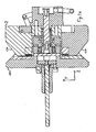
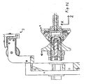
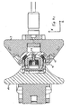
- the exemplary device according to the invention has a receiving tool 2 and an abutment tool 10, which can be moved together in the direction of the axis Z, so that a stator half-shell 1 can be fixed between the tools.
- the exemplary receiving tool according to the invention has a guide 18 for the starting wire of the coil winding and a further guide 19, with which the second wire end can be guided out of the coil, for example, in the other methods can be contacted electrically to allow a caking.
- the receiving tool 2, the pressure device 15. This is designed such that it can embrace the insulating material 9 and press in the direction of the outer side 17 of the stator half-shell 1 to the stator 13. The necessary change in the direction of movement of the pressure device 15 during gripping and subsequent pressing of the insulating material 9 to the stator 13 is thereby made possible by the L-shaped slotted guide 16.
- Sliding elements 20 are provided on the abutment tool 11, which can press the coil 4 into the groove between the stator wall 13 and the pole horns 8 of the stator half-shell 1 accommodated on the receiving tool 2.
- the abutment tool 10 has a clamping device 14, which serves to fix the insulation material 9 in the region of the pole horns 8.
- the rotating winding tool 3 rotates about the rotation axis R, which runs longitudinally parallel to the collapsing direction Z of the receiving tool 2 and counter-bearing tool 10 and perpendicular to the stator axis, which is arranged longitudinally parallel to the direction Y, the stator axis intersects.
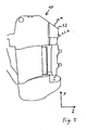
- the wire deflection element 12 is arranged in the region of the winding head 11.
- This undercut ensures that the wire 4 comes to rest freely after sliding off the Drahtabgleit Structure 12a in the direction of its desired position on the winding.
Description
Die Erfindung betrifft ein Verfahren und eine Vorrichtung für die Bewicklung von Statorhalbschalen.The invention relates to a method and a device for the winding of Statorhalbschalen.
Bei zweipoligen Statoren für Elektromotoren, wie sie z.B. in Handwinkelschleifern oder Handbohrmaschinen eingesetzt werden, besteht das Problem, den zu einer Spule zu wickelnden Draht beim Bewickeln in die Freiräume zwischen der Statorwand und den an der Innenseite der Statorhalbschalen vorstehenden Polhörnern einzubringen.For bipolar stators for electric motors, as e.g. used in manual angle grinders or hand drills, there is the problem of introducing the wire to be wound into a coil when winding in the spaces between the stator wall and on the inside of the Statorhalbschalen projecting pole horns.
Eine derzeitige Möglichkeit, dieses Problem zu lösen, besteht darin, den Draht zunächst zu einer Spule zu wickeln und dann in die Nuten zwischen Polhörnern und Statorwänden einzusetzen. Dabei werden die Feldspulen mit Isolationspapier versehen, welches die Feldspulen von der regelmäßig als Blechpaket ausgeführten Statorhalbschale trennt. Das Papier muss in einem umständlichen Verfahren um die Wirkstränge der Spule gefaltet und beispielsweise mit einem Klebestreifen gesichert werden.A current way to solve this problem is to first wind the wire into a coil and then insert it into the grooves between pole horns and stator walls. The field coils are provided with insulating paper which separates the field coils from the stator half shell, which is regularly designed as a laminated core. The paper must be folded in a cumbersome process to the effective strands of the coil and secured, for example, with an adhesive strip.
Wird eine fertig gewickelte Spule in die Nuten eingebracht, so müssen die Nuten geometrisch so geformt sein, dass die fertig geformte Spule über die Polhörner gezogen werden kann.When a fully wound coil is inserted into the grooves, the grooves must be geometrically shaped so that the finished formed coil can be pulled over the pole horns.
Hieraus ergibt sich eine Beschränkung der möglichen Geometrie der Polhörner, welche zum einen zu einer im Hinblick auf den magnetischen Fluss nicht optimalen Gestaltung der Polhörner, zum anderen zu einer nicht vollständigen Auffüllung des Nutgrundes führt. Soll die Spule nach dem Einbringen in die Nuten mit einer Beschichtung versehen werden, indem sie beispielsweise in einem Kurzschlussverfahren elektrisch gewärmt und in ein Pulverbad getaucht wird, so muss die Spule dabei zusätzlich in Form gehalten werden, damit sich die Geometrie, die bei dem Einsetzvorgang erzeugt worden ist, nicht verändert.This results in a limitation of the possible geometry of the pole horns, which on the one hand leads to a not optimal in terms of the magnetic flux design of the Polhörner, on the other hand to an incomplete filling of the groove bottom. If the coil is to be provided with a coating after being introduced into the grooves, for example by electrically heating them in a short circuit process and immersing them in a powder bath, the coil must additionally be kept in shape so that the geometry that is present during the insertion process has been generated, not changed.
Eine weitere Möglichkeit zur Bewicklung einer derartigen Statorhalbschale ist das Direktbewickeln mit einem Nadelwickelsystem. Dabei finden in der Regel Kunststoff-Isolierteile Verwendung, die die Isolation zwischen dem Draht und der Statorhalbschale gewährleisten. Nachteilig ist hierbei, dass der entstehende Wickelkopf bei dem Nadelwickelverfahren nicht die gewünschte halbkreisförmige Form annimmt, so dass das Ziel einer möglichst kompakten Gestaltung des Stators nicht im ausreichenden Maße erreicht werden kann. Weiterhin verschlechtern die Kunststoff-Isolierteile den Füllgrad der Nutschlitze und damit die Effizienz der resultierenden Statoren.Another way to wind such a stator half-shell is direct winding with a needle winding system. As a rule, plastic insulating parts are used which ensure the insulation between the wire and the stator half shell. The disadvantage here is that the resulting winding head does not take the desired semicircular shape in the needle winding process, so that the goal of a compact design of the stator can not be achieved to a sufficient extent. Furthermore, the plastic insulating parts worsen the degree of filling of the slot slots and thus the efficiency of the resulting stators.
Das Dokument
Weiterhin sind aus der
Der Erfindung liegt daher die Aufgabe zugrunde, ein Verfahren und eine Vorrichtung zur Wicklung eines Drahtes zu einer Spule für einen zweipoligen Stator anzugeben, welche die erwähnten Nachteile nicht oder in reduziertem Maße aufweisen.The invention is therefore based on the object to provide a method and an apparatus for winding a wire to a coil for a two-pole stator, which do not have the disadvantages mentioned or to a reduced extent.
Gelöst wird die Aufgabe durch ein Verfahren mit den Merkmalen des Anspruchs 1 und eine Vorrichtung mit den Merkmalen des Anspruchs 7. Die Merkmale der Unteransprüche betreffen vorteilhafte Ausführungsformen.The object is achieved by a method having the features of claim 1 and a device having the features of claim 7. The features of the subclaims relate to advantageous embodiments.
Erfindungsgemäß wird eine zu bewickelnde Statorhalbschale an einem Aufnahmewerkzeug aufgenommen. Dabei weist die Außenseite der Statorhalbschale zu dem Aufnahmewerkzeug hin. Ein Gegenlagerwerkzeug greift an der Innenseite der Statorhalbschale an, so dass die Nuten zwischen den Polhörnern und der Statorwand durch einen Spalt zwischen dem Aufnahmewerkzeug und dem Gegenlagerwerkzeug zugänglich sind. Ein Wickelwerkzeug, welches vorzugsweise um eine Achse rotiert, insbesondere ein sogenannter Flyer, dient zur Zuführung des Drahtes. Dabei ist die Statorhalbschale relativ zur Rotationsachse des Wickelwerkzeugs so positioniert, dass die Längsachse eines mit der Statorhalbschale gebildeten Stators die Rotationsachse des Wickelwerkzeugs rechtwinklig schneiden würde. Insbesondere läuft die Rotationsachse dabei durch den Schwerpunkt der Projektionsfläche der am Aufnahmewerkzeug aufgenommenen Statorhalbschale in Richtung der Rotationsachse.According to the invention, a stator half-shell to be wound is received on a receiving tool. In this case, the outside of the stator half shell points towards the receiving tool. An abutment tool engages the inside of the Statorhalbschale, so that the grooves between the pole horns and the stator are accessible through a gap between the receiving tool and the abutment tool. A winding tool, which preferably rotates about an axis, in particular a so-called flyer, serves to feed the wire. In this case, the stator half-shell is positioned relative to the axis of rotation of the winding tool such that the longitudinal axis of a stator formed with the stator half-shell would cut the axis of rotation of the winding tool at right angles. In particular, the axis of rotation passes through the center of gravity of the projection surface of the stator half-shell received on the receiving tool in the direction of the axis of rotation.
Erfindungsgemäß ist vorgesehen, dass der Draht beim Bewickeln im Bereich des Wickelkopfs in Richtung der Außenseite der an dem Aufnahmewerkzeug aufgenommenen Statorhalbschale abgelenkt wird. Hierfür weist das Gegenlagerwerkzeug im Bereich mindestens eines Wickelkopfes der zu erzeugenden Spule ein Drahtablenkelement auf.According to the invention, during winding in the region of the winding head, the wire is deflected in the direction of the outside of the stator half-shell accommodated on the receiving tool. For this purpose, the abutment tool in the region of at least one winding head of the coil to be generated on a wire deflector.
Das Drahtablenkelement tritt dabei in Richtung der Außenseite der am Aufnahmewerkzeug aufgenommenen Statorhalbschale aus der Kontur des Gegenlagerwerkzeugs hervor. Für die geometrische Gestaltung des Drahtablenkelements ist wichtig, dass es in ausreichendem Maße abgerundet ist, so dass der an dem Ablenkelement vorbei streichende Draht nicht durch scharfe Kanten oder ähnliches beschädigt werden kann. Des Weiteren muss das Ablenkelement so gestaltet sein, dass es bei einer geeignet gewählten Wickelgeschwindigkeit, was insbesondere bedeutet, bei einer geeignet gewählten Drehzahl des rotierenden Wickelwerkzeugs, dem vom Wickelwerkzeug zur bereits fertigen Wicklung sich erstreckenden Drahtabschnitt einen Bewegungsimpuls in Richtung der Außenseite der Statorhalbschale, d.h. in Richtung des Aufnahmewerkzeugs zu verleihen.The wire deflection occurs in the direction of the outside of the recorded on the receiving tool stator half shell out of the contour of the abutment tool. It is important for the geometrical configuration of the wire deflection member to be sufficiently rounded so that the wire passing the deflection member can not be damaged by sharp edges or the like. Furthermore, the deflection element must be designed in this way be that at a suitably selected winding speed, which means in particular at a suitably selected speed of the rotating winding tool, the wire from the winding tool for already finished winding extending wire section to impart a movement impulse toward the outside of the stator half shell, ie in the direction of the picking tool.
Vorzugsweise sind daher die Flächen, die in Richtung der Längsachse der Statorhalbschale orientiert sind, d.h. die Flächen, an denen der Draht beim Bewickeln abgleitet, so ausgebildet, dass sie eine zum Aufnahmewerkzeug hin abschüssige Abgleitfläche bilden. Wenn der Draht durch das rotierende Wickelwerkzeug über diese Fläche gezogen wird, so erhält der Drahtabschnitt einen Bewegungsimpuls, durch den der Draht aufgrund seiner Eigenträgheit in die hinteren Bereiche der Nuten, d.h. in die Statorwand seitigen Bereiche am Grund der Nut befördert wird, anstelle sich Windung für Windung entlang der Polhörner an diese anzulegen und einen Statorwand seitigen Raumbereich der Nut nicht erreichen zu können.Preferably, therefore, the surfaces oriented in the direction of the longitudinal axis of the stator half-shell, i. the surfaces on which the wire slides during winding, are formed such that they form a sloping to the receiving tool down sliding surface. As the wire is pulled over this surface by the rotating winding tool, the wire section receives a momentum through which the wire, due to its self-inertia, penetrates into the rear portions of the grooves, i. in the stator wall-side areas at the bottom of the groove is conveyed, instead of winding for turn along the pole horns to invest this and can not reach a stator wall-side space region of the groove can.
Dabei verliert der Drahtabschnitt zwischen dem Wickelwerkzeug und dem bereits zur Spule gewickelten Drahtabschnitt nach der Ablenkung durch das Drahtablenkelement vorzugsweise den Kontakt zu dem Drahtablenkelement, bevor er seine Endposition in der zu wickelnden Spule einnimmt. Dies bedeutet, dass der Draht durch das Drahtablenkelement nicht berührend in seine Endposition geführt wird, sondern nur die auf dessen Trägheit beruhende Flugbahn des Drahtes derart beeinflusst wird, dass diese im ansonsten schwer zu erreichenden Bereich des Nutgrundes endet.In this case, the wire section between the winding tool and the already wound to the coil wire section after being deflected by the wire deflection preferably loses contact with the Drahtablenkelement before it assumes its final position in the coil to be wound. This means that the wire is guided by the wire deflector not touching in its end position, but only based on the inertia trajectory of the wire is influenced such that it ends in otherwise difficult to reach area of the groove bottom.
Vorteilhafterweise weist das Gegenlagerwerkzeug Schieberelemente auf, mit denen die Drahtabschnitte, die zwischen den Polhörnern und der Statorwand in den Nuten verlaufen, in Richtung des Aufnahmewerkzeugs gedrückt werden können. Bei der Bewicklung ergibt sich aufgrund des mechanischen Biegewiderstands des Drahtes eine Ausbauchung des gewickelten Drahtes, der zwischen den Polhörnern und der Statorwand in den Nuten verläuft. Der Draht verläuft folglich nicht wie gewünscht längsparallel zur Statorlängsachse, sondern in Biegungen. Daher ist es vorteilhaft vorzusehen, dass Schieberelemente einen Druck auf die Drahtwicklung in den Nuten ausüben, um so den gewünschten, zur Statorlängsachse längsparallelen Idealverlauf der Drähte und die damit verbundene möglichst hohe Nutausfüllung so weit wie möglich zu ermöglichen.Advantageously, the abutment tool on slide elements with which the wire sections which extend between the pole horns and the stator in the grooves, can be pressed in the direction of the receiving tool. During winding, due to the mechanical bending resistance of the wire, there is a bulging of the wound wire extending between the pole horns and the stator wall in the grooves. Consequently, the wire does not run longitudinally parallel to the longitudinal axis of the stator as desired, but rather in bends. Therefore, it is advantageous to provide that slide elements exert a pressure on the wire winding in the grooves, so as to allow the desired, parallel to the longitudinal axis of the stator ideal course of the wires and the highest possible Nutausfüllung connected as far as possible.
Weiterhin ist es vorteilhaft, wenn das Aufnahmewerkzeug eine Andruckvorrichtung zur Fixierung eines Isolationsmaterials in der Statorwand aufweist. Bei dem Isolationsmaterial kann es sich beispielsweise um ein Papier handeln, das zwischen den Wicklungen der Spule und der Statorhalbschale für eine elektrische Isolierung sorgen soll. Das Isolationsmaterial wird dazu vor der Bewicklung in die Nut zwischen Statorwand und Polhorn eingelegt. Um eine Beschädigung des Isolationsmaterials beim Bewickeln zu vermeiden, ist es vorteilhaft, dies im Bereich der Statorwand zu fixieren. Die Fixierung kann dabei erfolgen, indem das Isolationsmaterial an die Statorwand angedrückt wird.Furthermore, it is advantageous if the receiving tool has a pressure device for fixing an insulating material in the stator wall. The insulating material can be, for example, a paper intended to provide electrical insulation between the windings of the coil and the stator half-shell. The insulating material is inserted before winding in the groove between the stator wall and the pole piece. In order to avoid damage to the insulating material during winding, it is advantageous in the field of Fix the stator wall. The fixation can be carried out by the insulating material is pressed against the stator.
Vorteilhafterweise geschieht der Andruck in Richtung der Außenseite der Statorhalbschale, um ein optimales Anliegen des Papiers zu gewährleisten. Die hierfür am Aufnahmewerkzeug vorgesehene Andruckvorrichtung muss hierzu in einer Bewegung geführt werden, in der die Andruckvorrichtung zunächst das Isolationsmaterial von der Außenseite der Statorhalbschale her kommend umgreift und dann in einer zur Außenseite der Statorhalbschale hin gerichteten Bewegung das Isolationsmaterial an die Statorwand andrückt. Hierfür kann beispielsweise eine Kulissenführung vorgesehen sein, die eine gewinkelte, insbesondere eine L-förmige Kontur aufweist, um die Änderung der Bewegungsrichtung vom Umgreifen zum Andrücken des Isolationsmaterials zu bewirken.Advantageously, the pressure occurs in the direction of the outside of the stator half-shell in order to ensure optimum contact of the paper. The purpose of this provided on the receiving tool pressure device must be performed for this purpose in a movement in which the pressure device initially embraces the insulating material coming from the outside of Statorhalbschale ago and then presses in a directed to the outside of the stator half-shell towards the insulating material to the stator wall. For this purpose, for example, a slotted guide may be provided, which has an angled, in particular an L-shaped contour to effect the change of the direction of movement from gripping to pressing the insulating material.
Weiterhin ist es vorteilhaft, das Isolationsmaterial nicht nur im Bereich der Statorwand, sondern auch im Bereich der Polhörner zu fixieren. Die Fixierung geschieht dabei vorzugsweise durch das Gegenlagerwerkzeug, indem insbesondere das Isolationsmaterial durch dieses eingeklemmt wird.Furthermore, it is advantageous to fix the insulation material not only in the region of the stator wall, but also in the region of the pole horns. The fixation is done preferably by the abutment tool, in particular by the insulating material is clamped by this.
Vorzugsweise weist das Gegenlagerwerkzeug hierfür eine Klemmvorrichtung auf, die im Bereich der Polhörner einer am Aufnahmewerkzeug aufgenommenen Statorhalbschale angeordnet ist. Diese Klemmvorrichtung wird vorzugsweise durch eine Mechanik beim Angriff des Gegenlagerwerkzeugs an der Statorhalbschale betätigt und klemmt dadurch selbsttätig beim Zusammenfahren von Aufnahmewerkzeug und Gegenlagerwerkzeug das Isolationsmaterial ein.For this purpose, the abutment tool preferably has a clamping device which is arranged in the region of the pole horns of a stator half-shell received on the receiving tool. This clamping device is preferably actuated by a mechanism during the attack of the abutment tool on the stator half shell and thereby automatically clamps when moving together of receiving tool and abutment tool, the insulation material.
Weiterhin ist es vorteilhaft, dass das Aufnahmewerkzeug eine Führung, die insbesondere als Vertiefung oder Kanal gestaltet ist, aufweist, die durch ihre Positionierung am Aufnahmewerkzeug geeignet ist, zu Beginn des Wickelvorgangs den in das Werkzeug einlaufenden Draht an den zu bewickelnden Bereich zwischen einem Polhorn und der Statorwand heranzuführen, bzw. einen Freiraum für das zur Spule führende Drahtende bereit stellt, so dass dieses Drahtende bei der Bewicklung in diesen Freiraum ausweichen kann und nicht durch den Aufbau der Wicklung geschädigt wird.Furthermore, it is advantageous that the receiving tool has a guide, which is designed in particular as a depression or channel, which is suitable by their positioning on the receiving tool, at the beginning of the winding process, the incoming wire in the tool to the area to be wound between a pole piece and bring the stator wall, or provides a free space for the wire end leading to the coil, so that this wire end can dodge in the winding in this space and is not damaged by the structure of the winding.
Vorteilhafterweise wird vor dem Entnehmen der bewickelten Statorhalbschale aus dem Aufnahmewerkzeug die Spule elektrisch kontaktiert und durch das Anlegen eines elektrischen Stromes aufgeheizt, wobei eine auf dem Draht aufgebrachte Beschichtung zumindest teilweise temporär aufgeschmolzen wird. Dabei erreicht der Draht vorzugsweise eine Temperatur, die geeignet ist, eine vorzugsweise thermoplastische Beschichtung auf dem Draht zumindest so weit aufzuschmelzen, dass ein Verbacken der Drähte miteinander erzielt wird. Dementsprechend handelt es sich bei der Beschichtung insbesondere um einen Backlack, welcher beim Abkühlen nach dem Verbacken noch eine hinreichende elektrische Isolation der einzelnen Windungen der Spule untereinander gewährleistet. Die Temperatur, die zum Verbacken erreicht werden muss, hängt vom Draht, insbesondere von der Beschichtung des Drahtes ab. Vorzugsweise beträgt die Temperatur dabei 220°C +/- 20°C.Advantageously, prior to removal of the wound Statorhalbschale from the receiving tool, the coil electrically contacted and heated by the application of an electric current, wherein a coating applied to the wire coating is at least partially melted temporarily. In this case, the wire preferably reaches a temperature which is suitable for melting a preferably thermoplastic coating on the wire at least to the extent that caking of the wires is achieved with one another. Accordingly, the coating is in particular a baked enamel, which, upon cooling after baking, still provides sufficient electrical insulation of the individual turns of the Coil ensured with each other. The temperature that has to be reached for baking depends on the wire, in particular on the coating of the wire. The temperature is preferably 220 ° C +/- 20 ° C.
Vorteilhafterweise kann auf die Spule eine Pulverbeschichtung aufgebracht werden, wobei vorzugsweise die Restwärme eines vorhergehenden Aufheizens des Drahtes, beispielsweise zum Verbacken der einzelnen Windungen mit einem Backlack, genutzt wird, um die Pulverbeschichtung selektiv auf dem Draht aufzubringen. Hierzu wird die bewickelte Statorhalbschale mit dem noch heißen Draht in ein Pulverbad eingebracht, mit dem Ergebnis, dass das Pulver selektiv auf dem Draht, nicht aber auf der Statorhalbschale anhaftet und anschmilzt, so dass sich im Ergebnis eine Pulverbeschichtung nur des Drahtes ergibt. Der Pulverbeschichtungsvorgang findet vorzugsweise bei Temperaturen um ca. 150°C statt. Wird die Restwärme des Verbackprozesses genutzt, so muss dieser bei einer ausreichend hohen Temperatur stattfinden, um eine ausreichend lange Abkühlphase zu verursachen. Diese wird benötigt, um ausreichend Zeit zu haben, die bewickelten Statorhalbschalen aus der Vorrichtung zu entnehmen und in das Pulverbad einzubringen.Advantageously, a powder coating can be applied to the coil, wherein preferably the residual heat of a previous heating of the wire, for example, used to bake the individual turns with a baked enamel, is used to selectively apply the powder coating on the wire. For this purpose, the wound Statorhalbschale is introduced with the still hot wire in a powder bath, with the result that the powder selectively on the wire, but not on the Statorhalbschale adheres and melts, so that the result is a powder coating only the wire. The powder coating process preferably takes place at temperatures of about 150 ° C. If the residual heat of the Verbackprozesses used, it must take place at a sufficiently high temperature to cause a sufficiently long cooling phase. This is required in order to have sufficient time to remove the wound stator half-shells from the device and to introduce them into the powder bath.
Die Erfindung wird im Folgenden anhand der
- Figur 1 -
- eine schematische, perspektivische Ansicht eines zusammengefahrenen Verbunds aus Aufnahmewerkzeug und Gegenlagerwerkzeug,
Figur 2 und Figur 2a -- Schnittdarstellungen einer beispielhaften erfindungsgemäßen Vorrichtung in einer parallel zur Statorachse verlaufenden Schnittebene,
Figur 3 und Figur 3a -- Draufsichten aus Richtung der Statorhalbachse auf eine beispielhafte erfindungsgemäße Vorrichtung,
- Figur 4 bis Figur 4c -
- Schnittdarstellungen einer beispielhaften erfindungsgemäßen Vorrichtung mit einer rechtwinklig zur Statorhalbachse verlaufenden Schnittebene,
- Figur 5 -
- eine vereinfachte schematische Darstellung eines beispielhaften erfindungsgemäßen Gegenlagerwerkzeugs.
- FIG. 1 -
- a schematic, perspective view of a collapsed composite of receiving tool and abutment tool,
- FIG. 2 and FIG. 2a -
- Sectional views of an exemplary device according to the invention in a plane parallel to the stator axis cutting plane,
- FIG. 3 and FIG. 3a -
- Top views from the direction of the stator half-axis on an exemplary device according to the invention,
- 4 to 4c -
- Sectional views of an exemplary device according to the invention with a sectional plane perpendicular to the stator half-axis,
- FIG. 5 -
- a simplified schematic representation of an exemplary abutment tool according to the invention.
Die beispielhafte erfindungsgemäße Vorrichtung weist ein Aufnahmewerkzeug 2 und ein Gegenlagerwerkzeug 10 auf, welche in Richtung der Achse Z zusammengefahren werden können, so dass eine Statorhalbschale 1 zwischen den Werkzeugen fixiert werden kann. Das beispielhafte erfindungsgemäße Aufnahmewerkzeug weist eine Führung 18 für den Startdraht der Spulenwicklung auf sowie eine weitere Führung 19, mit der das zweite Drahtende wieder aus der Spule hinaus geführt werden kann, beispielsweise um im weiteren Verfahren elektrisch kontaktiert werden zu können, um ein Verbacken zu ermöglichen.The exemplary device according to the invention has a receiving
Weiterhin weist das Aufnahmewerkzeug 2 die Andruckvorrichtung 15 auf. Diese ist derart gestaltet, dass sie das Isolationsmaterial 9 umgreifen und in Richtung der Außenseite 17 der Statorhalbschale 1 an die Statorwand 13 andrücken kann. Die notwendige Änderung der Bewegungsrichtung der Andruckvorrichtung 15 beim Umgreifen und anschließenden Andrücken des Isolationsmaterials 9 an die Statorwand 13 wird dabei durch die L-förmige Kulissenführung 16 ermöglicht.Furthermore, the receiving
Am Gegenlagerwerkzeug 11 sind Schieberelemente 20 vorgesehen, welche die Spule 4 in die Nut zwischen der Statorwand 13 und den Polhörnern 8 der am Aufnahmewerkzeug 2 aufgenommenen Statorhalbschale 1 drücken können.Sliding elements 20 are provided on the abutment tool 11, which can press the coil 4 into the groove between the
Weiterhin verfügt das Gegenlagerwerkzeug 10 über eine Klemmvorrichtung 14, welche dazu dient, das Isolationsmaterial 9 im Bereich der Polhörner 8 zu fixieren.Furthermore, the
Das rotierende Wickelwerkzeug 3 rotiert um die Rotationsachse R, welche längsparallel zur Zusammenschieberichtung Z von Aufnahmewerkzeug 2 und Gegenlagerwerkzeug 10 verläuft und rechtwinklig zur Statorachse, welche längsparallel zur Richtung Y angeordnet ist, die Statorachse schneidet.The rotating winding
Im Bereich des Wickelkopfes 11 ist das Drahtablenkelement 12 angeordnet. Dieses weist zum einen die Drahtabgleitfläche 12a auf, an der der Draht beim Bewickeln mit dem rotierenden Wickelwerkzeug abgleitet und so einen Impuls in Richtung Aufnahmewerkzeug erhält, sowie eine leichte Hinterschneidung 12b, die sich bei der Draufsicht aus einer zur Statorachse parallelen Richtung Y ergibt. Diese Hinterschneidung sorgt dafür, dass der Draht 4 nach dem Abgleiten von der Drahtabgleitfläche 12a frei fliegend in Richtung seiner Solllage auf der Wicklung zum Liegen kommt.In the region of the winding head 11, the
Claims (13)
- Method for winding a wire (4) into a coil (5) for a double-pole stator, wherein a stator half shell (1) is received on a mounting tool (2), a counter bearing tool (10) engages on the inside (7) of the stator half shell (1), and the stator half shell (1) is wound up by a winding tool (3), more particularly a flyer, which rotates about an axis of rotation relative to the mounting tool (2) and the counter bearing tool (10), wherein the wire during winding is deflected in the region of the winding head (11) in the direction of the outside (17) of the stator half shell (1) which is received on the mounting tool (2), more particularly in that the wire (4) is guided by the rotating winding tool (3) along a wire deflection element which emerges from the contour of the counter bearing tool (10), wherein the stator half shell (1) is positioned relative to the axis of rotation of the winding tool (3) so that the longitudinal axis of a stator which is formed with the stator half shell (1) would intersect at right angles the axis of rotation of the winding tool (3).
- Method according to claim 1,
characterised in that
the wire section loses contact with the wire deflection element (12) between the rotating winding tool (3) and the wire section already wound into the coil (5) after deflection in the direction of the outside (17) of the stator half shell (1) received on the mounting tool (2), before it occupies its end position. - Method according to claim 1 or 2,
characterised in that
an insulation material (9), more particularly a paper, is fixed on the stator half shell (1) in the region of the stator wall (13), more particularly is pressed against the stator wall (13), wherein the fixing, more particularly the contact pressure, is undertaken on the stator wall (13) preferably in the direction of the outside (17) of the stator half shell (1) received on the mounting tool (2). - Method according to one of the preceding claims,
characterised in that
an insulation material (9), more particularly a paper, is fixed, preferably clamped, in the region of the pole horns (8), preferably by the counter bearing tool (10). - Method according to one of the preceding claims
characterised in that
prior to removing the wound stator half shell (1) from the mounting tool (2), the coil (5) is electrically contacted and is heated up, preferably to 220° C +/- 20° C, by applying an electrical current, wherein a coating, preferably a thermoplastics coating applied to the wire (4) is melted at least partially temporarily. - Method according to one of the preceding claims,
characterised in that
a powder coating is applied to the coil (5) wherein the residual heat of a previous heating up of the wire (4) is advantageously used, preferably at a temperature of the wire of about 150° C. - Device for winding a wire (40 into a coil (5) for a double-pole stator, a mounting tool (2) for receiving a stator half shell (1), having a counter bearing tool (10) and a winding tool (3), more particularly a flyer, which rotates about a rotational axis, wherein the counter bearing tool (10) has in the region of at least one winding head (11) of the coil (5) which is to be produced, a wire deflection element (12),
characterised in that
the stator half shell (1) can be positioned relative to the axis of rotation of the winding tool (3) so that the longitudinal axis of a stator formed with the stator half shell (1) would intersect the rotational axis of the winding tool (3) at right angles. - Device according to claim 7
characterised in that
the wire deflection element (12) emerges from the contour of the counter bearing tool (10) in the direction of the outside (17) of the stator half shell (1) received on the mounting tool (2). - Device according to one of claims 7 or 8
characterised in that
the counter bearing tool (10) has a clamping device (14) for fixing an insulation material (9) in the region of the pole horns (8) of a stator half shell (10) received on the mounting tool (2). - Device according to one of claims 7 to 9
characterised in that
the mounting tool (2) has a contact pressure device (15) for fixing an insulation material (9) on the stator wall (13). - Device according to claim 10
characterised in that
the contact pressure device has a slide guide (16) wherein the slide guide (16) has a contour which is in particular angled, and preferably L-shaped. - Device according to one of claims 7 to 11
characterised in that
the mounting tool (2) has a guide (18), more particularly an indentation or a channel, which is suitable to bring the wire (4) at the start of the winding process up to the area which is to be wound between a pole horn (8) and the stator wall (13) and/or to provide a free space for the wire end which is running to the coil. - Device according to one of claims 7 to 12
characterised in that
the counter bearing tool (10) has slide elements (20) which are suitable to press wire sections, which are running between the pole horns (8) and the stator wall (13), in the direction of the mounting tool (2).
Priority Applications (3)
| Application Number | Priority Date | Filing Date | Title |
|---|---|---|---|
| PL12003607T PL2536008T3 (en) | 2011-06-18 | 2012-05-09 | Method and device for winding stator half shells |
| SI201230132T SI2536008T1 (en) | 2011-06-18 | 2012-05-09 | Method and device for winding stator half shells |
| HRP20150033AT HRP20150033T1 (en) | 2011-06-18 | 2015-01-12 | Method and device for winding stator half shells |
Applications Claiming Priority (1)
| Application Number | Priority Date | Filing Date | Title |
|---|---|---|---|
| DE102011104380A DE102011104380A1 (en) | 2011-06-18 | 2011-06-18 | Method and device for wrapping stator half-shells |
Publications (3)
| Publication Number | Publication Date |
|---|---|
| EP2536008A2 EP2536008A2 (en) | 2012-12-19 |
| EP2536008A3 EP2536008A3 (en) | 2013-02-20 |
| EP2536008B1 true EP2536008B1 (en) | 2014-10-22 |
Family
ID=46172653
Family Applications (1)
| Application Number | Title | Priority Date | Filing Date |
|---|---|---|---|
| EP12003607.4A Not-in-force EP2536008B1 (en) | 2011-06-18 | 2012-05-09 | Method and device for winding stator half shells |
Country Status (6)
| Country | Link |
|---|---|
| EP (1) | EP2536008B1 (en) |
| DE (1) | DE102011104380A1 (en) |
| ES (1) | ES2528271T3 (en) |
| HR (1) | HRP20150033T1 (en) |
| PL (1) | PL2536008T3 (en) |
| SI (1) | SI2536008T1 (en) |
Families Citing this family (1)
| Publication number | Priority date | Publication date | Assignee | Title |
|---|---|---|---|---|
| CN115632530B (en) * | 2022-10-25 | 2023-09-01 | 深圳市金岷江智能装备有限公司 | Winding equipment |
Family Cites Families (6)
| Publication number | Priority date | Publication date | Assignee | Title |
|---|---|---|---|---|
| US3648938A (en) * | 1970-08-05 | 1972-03-14 | Universal Electric Co | Winding of electric motors |
| JPS59117446A (en) * | 1982-12-23 | 1984-07-06 | Tamagawa Seiki Kk | Wire guide device for flier type winding machine |
| US5182848A (en) * | 1987-07-24 | 1993-02-02 | Black & Decker Inc. | Method for assembling a stator subassembly |
| CA2092264A1 (en) * | 1992-04-15 | 1993-10-16 | Massimo Ponzio | Stator winding methods and apparatus |
| EP1225679B1 (en) | 2001-01-19 | 2004-08-18 | ATS Wickel- und Montagetechnik AG | Method and apparatus for winding field coils of two-pole stators |
| JP2009118676A (en) * | 2007-11-08 | 2009-05-28 | Hitachi Koki Co Ltd | Power tool |
-
2011
- 2011-06-18 DE DE102011104380A patent/DE102011104380A1/en not_active Withdrawn
-
2012
- 2012-05-09 PL PL12003607T patent/PL2536008T3/en unknown
- 2012-05-09 SI SI201230132T patent/SI2536008T1/en unknown
- 2012-05-09 EP EP12003607.4A patent/EP2536008B1/en not_active Not-in-force
- 2012-05-09 ES ES12003607.4T patent/ES2528271T3/en active Active
-
2015
- 2015-01-12 HR HRP20150033AT patent/HRP20150033T1/en unknown
Also Published As
| Publication number | Publication date |
|---|---|
| HRP20150033T1 (en) | 2015-02-27 |
| EP2536008A3 (en) | 2013-02-20 |
| ES2528271T3 (en) | 2015-02-06 |
| EP2536008A2 (en) | 2012-12-19 |
| SI2536008T1 (en) | 2015-03-31 |
| PL2536008T3 (en) | 2015-03-31 |
| DE102011104380A1 (en) | 2012-12-20 |
Similar Documents
| Publication | Publication Date | Title |
|---|---|---|
| EP3391512B1 (en) | Method for introducing insulating film and at least one electrical conductor | |
| EP2477315A2 (en) | Needle coiling system for coiling support to be coiled, method for coiling coiling supports with distributed coiling, internal rotor stator, external rotor and coiling support for electric motors with distributed coil | |
| DE3712226A1 (en) | ELECTRICAL MACHINE WITH A WINDING PACKAGE AND A METHOD FOR THEIR PRODUCTION | |
| DE2630183B2 (en) | Method and device for pulling windings into slots of armatures and stators of electric motors | |
| DE3013011A1 (en) | METHOD AND DEVICE FOR THE AXIAL PULL-IN OF THE WINDING HEAD INSULATION OF DYNAMOELECTRIC MACHINES | |
| EP2605374B1 (en) | Stator for an electric motor and method for manufacturing a stator for an electric motor | |
| EP3804048B1 (en) | Device and method for processing an end of an electrical cable | |
| EP2605382B1 (en) | Device and method for producing a stator and stator | |
| EP2536008B1 (en) | Method and device for winding stator half shells | |
| DE2328436C3 (en) | Intermediate layer for coil insulation in the winding heads of electrical machines | |
| DE7640891U1 (en) | DEVICE FOR BAKING BACKLACQUER INSULATED COIL WIRES | |
| DE102017213967A1 (en) | Device for processing windings | |
| EP2605384B1 (en) | Method for winding the field coils of a stator and this stator | |
| EP2605377B1 (en) | Device and method for producing a stator and stator | |
| EP2721724A2 (en) | Method and apparatus for winding a laminated core of an electric motor | |
| EP2845300B1 (en) | Apparatus and method for winding an electric-motor laminated core with a magnet coil | |
| EP3544161A1 (en) | Method and device for introducing a shaft coil mat into the rotor or stator of an electrical machine, in particular a laminated stator core | |
| DE3148890C2 (en) | ||
| DE102004060078A1 (en) | Strip of laminations for cores carrying coils of electrical motor or generator, comprises toothed projections between recesses, with yokes connected detachably to strip | |
| EP2665163B1 (en) | Winding pattern and method for producing a stator for an electric motor | |
| EP2605383A2 (en) | Method for producing a stator and stator | |
| EP2605385B1 (en) | Method for winding the magnetic coils of a stator and stator | |
| EP2605375B1 (en) | Stator for an electric motor and method for manufacturing a stator for an electric motor | |
| DE112014001874T5 (en) | Apparatus and method for producing a bobbin for an electric motor | |
| EP3504935B1 (en) | Method and device for arranging busbars on a sheet |
Legal Events
| Date | Code | Title | Description |
|---|---|---|---|
| PUAI | Public reference made under article 153(3) epc to a published international application that has entered the european phase |
Free format text: ORIGINAL CODE: 0009012 |
|
| AK | Designated contracting states |
Kind code of ref document: A2 Designated state(s): AL AT BE BG CH CY CZ DE DK EE ES FI FR GB GR HR HU IE IS IT LI LT LU LV MC MK MT NL NO PL PT RO RS SE SI SK SM TR |
|
| AX | Request for extension of the european patent |
Extension state: BA ME |
|
| PUAL | Search report despatched |
Free format text: ORIGINAL CODE: 0009013 |
|
| AK | Designated contracting states |
Kind code of ref document: A3 Designated state(s): AL AT BE BG CH CY CZ DE DK EE ES FI FR GB GR HR HU IE IS IT LI LT LU LV MC MK MT NL NO PL PT RO RS SE SI SK SM TR |
|
| AX | Request for extension of the european patent |
Extension state: BA ME |
|
| RIC1 | Information provided on ipc code assigned before grant |
Ipc: H02K 15/095 20060101AFI20130111BHEP |
|
| 17P | Request for examination filed |
Effective date: 20130412 |
|
| RBV | Designated contracting states (corrected) |
Designated state(s): AL AT BE BG CH CY CZ DE DK EE ES FI FR GB GR HR HU IE IS IT LI LT LU LV MC MK MT NL NO PL PT RO RS SE SI SK SM TR |
|
| GRAP | Despatch of communication of intention to grant a patent |
Free format text: ORIGINAL CODE: EPIDOSNIGR1 |
|
| INTG | Intention to grant announced |
Effective date: 20140207 |
|
| GRAP | Despatch of communication of intention to grant a patent |
Free format text: ORIGINAL CODE: EPIDOSNIGR1 |
|
| INTG | Intention to grant announced |
Effective date: 20140703 |
|
| GRAS | Grant fee paid |
Free format text: ORIGINAL CODE: EPIDOSNIGR3 |
|
| GRAA | (expected) grant |
Free format text: ORIGINAL CODE: 0009210 |
|
| AK | Designated contracting states |
Kind code of ref document: B1 Designated state(s): AL AT BE BG CH CY CZ DE DK EE ES FI FR GB GR HR HU IE IS IT LI LT LU LV MC MK MT NL NO PL PT RO RS SE SI SK SM TR |
|
| REG | Reference to a national code |
Ref country code: GB Ref legal event code: FG4D Free format text: NOT ENGLISH |
|
| REG | Reference to a national code |
Ref country code: CH Ref legal event code: EP |
|
| REG | Reference to a national code |
Ref country code: AT Ref legal event code: REF Ref document number: 693021 Country of ref document: AT Kind code of ref document: T Effective date: 20141115 |
|
| REG | Reference to a national code |
Ref country code: IE Ref legal event code: FG4D Free format text: LANGUAGE OF EP DOCUMENT: GERMAN |
|
| REG | Reference to a national code |
Ref country code: CH Ref legal event code: NV Representative=s name: SCHMAUDER AND PARTNER AG PATENT- UND MARKENANW, CH |
|
| REG | Reference to a national code |
Ref country code: DE Ref legal event code: R096 Ref document number: 502012001446 Country of ref document: DE Effective date: 20141204 |
|
| REG | Reference to a national code |
Ref country code: NL Ref legal event code: T3 |
|
| REG | Reference to a national code |
Ref country code: HR Ref legal event code: TUEP Ref document number: P20150033 Country of ref document: HR |
|
| REG | Reference to a national code |
Ref country code: RO Ref legal event code: EPE |
|
| REG | Reference to a national code |
Ref country code: ES Ref legal event code: FG2A Ref document number: 2528271 Country of ref document: ES Kind code of ref document: T3 Effective date: 20150206 |
|
| REG | Reference to a national code |
Ref country code: HR Ref legal event code: T1PR Ref document number: P20150033 Country of ref document: HR |
|
| REG | Reference to a national code |
Ref country code: LT Ref legal event code: MG4D |
|
| REG | Reference to a national code |
Ref country code: PL Ref legal event code: T3 |
|
| REG | Reference to a national code |
Ref country code: FR Ref legal event code: PLFP Year of fee payment: 4 |
|
| PG25 | Lapsed in a contracting state [announced via postgrant information from national office to epo] |
Ref country code: IS Free format text: LAPSE BECAUSE OF FAILURE TO SUBMIT A TRANSLATION OF THE DESCRIPTION OR TO PAY THE FEE WITHIN THE PRESCRIBED TIME-LIMIT Effective date: 20150222 Ref country code: LT Free format text: LAPSE BECAUSE OF FAILURE TO SUBMIT A TRANSLATION OF THE DESCRIPTION OR TO PAY THE FEE WITHIN THE PRESCRIBED TIME-LIMIT Effective date: 20141022 Ref country code: PT Free format text: LAPSE BECAUSE OF FAILURE TO SUBMIT A TRANSLATION OF THE DESCRIPTION OR TO PAY THE FEE WITHIN THE PRESCRIBED TIME-LIMIT Effective date: 20150223 Ref country code: NO Free format text: LAPSE BECAUSE OF FAILURE TO SUBMIT A TRANSLATION OF THE DESCRIPTION OR TO PAY THE FEE WITHIN THE PRESCRIBED TIME-LIMIT Effective date: 20150122 Ref country code: FI Free format text: LAPSE BECAUSE OF FAILURE TO SUBMIT A TRANSLATION OF THE DESCRIPTION OR TO PAY THE FEE WITHIN THE PRESCRIBED TIME-LIMIT Effective date: 20141022 |
|
| PG25 | Lapsed in a contracting state [announced via postgrant information from national office to epo] |
Ref country code: SE Free format text: LAPSE BECAUSE OF FAILURE TO SUBMIT A TRANSLATION OF THE DESCRIPTION OR TO PAY THE FEE WITHIN THE PRESCRIBED TIME-LIMIT Effective date: 20141022 Ref country code: RS Free format text: LAPSE BECAUSE OF FAILURE TO SUBMIT A TRANSLATION OF THE DESCRIPTION OR TO PAY THE FEE WITHIN THE PRESCRIBED TIME-LIMIT Effective date: 20141022 Ref country code: CY Free format text: LAPSE BECAUSE OF FAILURE TO SUBMIT A TRANSLATION OF THE DESCRIPTION OR TO PAY THE FEE WITHIN THE PRESCRIBED TIME-LIMIT Effective date: 20141022 Ref country code: LV Free format text: LAPSE BECAUSE OF FAILURE TO SUBMIT A TRANSLATION OF THE DESCRIPTION OR TO PAY THE FEE WITHIN THE PRESCRIBED TIME-LIMIT Effective date: 20141022 Ref country code: GR Free format text: LAPSE BECAUSE OF FAILURE TO SUBMIT A TRANSLATION OF THE DESCRIPTION OR TO PAY THE FEE WITHIN THE PRESCRIBED TIME-LIMIT Effective date: 20150123 |
|
| REG | Reference to a national code |
Ref country code: SK Ref legal event code: T3 Ref document number: E 18329 Country of ref document: SK |
|
| REG | Reference to a national code |
Ref country code: DE Ref legal event code: R097 Ref document number: 502012001446 Country of ref document: DE |
|
| REG | Reference to a national code |
Ref country code: HU Ref legal event code: AG4A Ref document number: E023307 Country of ref document: HU |
|
| PG25 | Lapsed in a contracting state [announced via postgrant information from national office to epo] |
Ref country code: EE Free format text: LAPSE BECAUSE OF FAILURE TO SUBMIT A TRANSLATION OF THE DESCRIPTION OR TO PAY THE FEE WITHIN THE PRESCRIBED TIME-LIMIT Effective date: 20141022 Ref country code: DK Free format text: LAPSE BECAUSE OF FAILURE TO SUBMIT A TRANSLATION OF THE DESCRIPTION OR TO PAY THE FEE WITHIN THE PRESCRIBED TIME-LIMIT Effective date: 20141022 |
|
| PLBE | No opposition filed within time limit |
Free format text: ORIGINAL CODE: 0009261 |
|
| STAA | Information on the status of an ep patent application or granted ep patent |
Free format text: STATUS: NO OPPOSITION FILED WITHIN TIME LIMIT |
|
| 26N | No opposition filed |
Effective date: 20150723 |
|
| PG25 | Lapsed in a contracting state [announced via postgrant information from national office to epo] |
Ref country code: LU Free format text: LAPSE BECAUSE OF FAILURE TO SUBMIT A TRANSLATION OF THE DESCRIPTION OR TO PAY THE FEE WITHIN THE PRESCRIBED TIME-LIMIT Effective date: 20150509 Ref country code: MC Free format text: LAPSE BECAUSE OF FAILURE TO SUBMIT A TRANSLATION OF THE DESCRIPTION OR TO PAY THE FEE WITHIN THE PRESCRIBED TIME-LIMIT Effective date: 20141022 |
|
| REG | Reference to a national code |
Ref country code: IE Ref legal event code: MM4A |
|
| PG25 | Lapsed in a contracting state [announced via postgrant information from national office to epo] |
Ref country code: IE Free format text: LAPSE BECAUSE OF NON-PAYMENT OF DUE FEES Effective date: 20150509 |
|
| REG | Reference to a national code |
Ref country code: FR Ref legal event code: PLFP Year of fee payment: 5 |
|
| PG25 | Lapsed in a contracting state [announced via postgrant information from national office to epo] |
Ref country code: MT Free format text: LAPSE BECAUSE OF FAILURE TO SUBMIT A TRANSLATION OF THE DESCRIPTION OR TO PAY THE FEE WITHIN THE PRESCRIBED TIME-LIMIT Effective date: 20141022 |
|
| GBPC | Gb: european patent ceased through non-payment of renewal fee |
Effective date: 20160509 |
|
| REG | Reference to a national code |
Ref country code: FR Ref legal event code: PLFP Year of fee payment: 6 |
|
| PG25 | Lapsed in a contracting state [announced via postgrant information from national office to epo] |
Ref country code: GB Free format text: LAPSE BECAUSE OF NON-PAYMENT OF DUE FEES Effective date: 20160509 Ref country code: SM Free format text: LAPSE BECAUSE OF FAILURE TO SUBMIT A TRANSLATION OF THE DESCRIPTION OR TO PAY THE FEE WITHIN THE PRESCRIBED TIME-LIMIT Effective date: 20141022 |
|
| PG25 | Lapsed in a contracting state [announced via postgrant information from national office to epo] |
Ref country code: TR Free format text: LAPSE BECAUSE OF FAILURE TO SUBMIT A TRANSLATION OF THE DESCRIPTION OR TO PAY THE FEE WITHIN THE PRESCRIBED TIME-LIMIT Effective date: 20141022 |
|
| REG | Reference to a national code |
Ref country code: HR Ref legal event code: ODRP Ref document number: P20150033 Country of ref document: HR Payment date: 20180502 Year of fee payment: 7 |
|
| REG | Reference to a national code |
Ref country code: FR Ref legal event code: PLFP Year of fee payment: 7 |
|
| PG25 | Lapsed in a contracting state [announced via postgrant information from national office to epo] |
Ref country code: MK Free format text: LAPSE BECAUSE OF FAILURE TO SUBMIT A TRANSLATION OF THE DESCRIPTION OR TO PAY THE FEE WITHIN THE PRESCRIBED TIME-LIMIT Effective date: 20141022 |
|
| PGFP | Annual fee paid to national office [announced via postgrant information from national office to epo] |
Ref country code: SK Payment date: 20180427 Year of fee payment: 7 Ref country code: DE Payment date: 20180427 Year of fee payment: 7 Ref country code: HR Payment date: 20180502 Year of fee payment: 7 Ref country code: CH Payment date: 20180523 Year of fee payment: 7 Ref country code: CZ Payment date: 20180502 Year of fee payment: 7 Ref country code: ES Payment date: 20180626 Year of fee payment: 7 |
|
| PGFP | Annual fee paid to national office [announced via postgrant information from national office to epo] |
Ref country code: PL Payment date: 20180427 Year of fee payment: 7 Ref country code: RO Payment date: 20180502 Year of fee payment: 7 Ref country code: SI Payment date: 20180503 Year of fee payment: 7 Ref country code: IT Payment date: 20180518 Year of fee payment: 7 Ref country code: NL Payment date: 20180523 Year of fee payment: 7 Ref country code: FR Payment date: 20180522 Year of fee payment: 7 Ref country code: BE Payment date: 20180523 Year of fee payment: 7 Ref country code: AT Payment date: 20180517 Year of fee payment: 7 Ref country code: BG Payment date: 20180521 Year of fee payment: 7 |
|
| PGFP | Annual fee paid to national office [announced via postgrant information from national office to epo] |
Ref country code: HU Payment date: 20180427 Year of fee payment: 7 |
|
| PG25 | Lapsed in a contracting state [announced via postgrant information from national office to epo] |
Ref country code: AL Free format text: LAPSE BECAUSE OF FAILURE TO SUBMIT A TRANSLATION OF THE DESCRIPTION OR TO PAY THE FEE WITHIN THE PRESCRIBED TIME-LIMIT Effective date: 20141022 |
|
| REG | Reference to a national code |
Ref country code: HR Ref legal event code: PBON Ref document number: P20150033 Country of ref document: HR Effective date: 20190509 |
|
| REG | Reference to a national code |
Ref country code: DE Ref legal event code: R119 Ref document number: 502012001446 Country of ref document: DE |
|
| REG | Reference to a national code |
Ref country code: CH Ref legal event code: PL |
|
| REG | Reference to a national code |
Ref country code: NL Ref legal event code: MM Effective date: 20190601 |
|
| REG | Reference to a national code |
Ref country code: AT Ref legal event code: MM01 Ref document number: 693021 Country of ref document: AT Kind code of ref document: T Effective date: 20190509 |
|
| PG25 | Lapsed in a contracting state [announced via postgrant information from national office to epo] |
Ref country code: CZ Free format text: LAPSE BECAUSE OF NON-PAYMENT OF DUE FEES Effective date: 20190509 Ref country code: HR Free format text: LAPSE BECAUSE OF NON-PAYMENT OF DUE FEES Effective date: 20190509 Ref country code: RO Free format text: LAPSE BECAUSE OF NON-PAYMENT OF DUE FEES Effective date: 20190509 Ref country code: HU Free format text: LAPSE BECAUSE OF NON-PAYMENT OF DUE FEES Effective date: 20190510 Ref country code: AT Free format text: LAPSE BECAUSE OF NON-PAYMENT OF DUE FEES Effective date: 20190509 Ref country code: CH Free format text: LAPSE BECAUSE OF NON-PAYMENT OF DUE FEES Effective date: 20190531 Ref country code: LI Free format text: LAPSE BECAUSE OF NON-PAYMENT OF DUE FEES Effective date: 20190531 Ref country code: SK Free format text: LAPSE BECAUSE OF NON-PAYMENT OF DUE FEES Effective date: 20190509 Ref country code: BG Free format text: LAPSE BECAUSE OF NON-PAYMENT OF DUE FEES Effective date: 20191130 |
|
| REG | Reference to a national code |
Ref country code: SI Ref legal event code: KO00 Effective date: 20191224 |
|
| REG | Reference to a national code |
Ref country code: SK Ref legal event code: MM4A Ref document number: E 18329 Country of ref document: SK Effective date: 20190509 |
|
| REG | Reference to a national code |
Ref country code: BE Ref legal event code: MM Effective date: 20190531 |
|
| PG25 | Lapsed in a contracting state [announced via postgrant information from national office to epo] |
Ref country code: SI Free format text: LAPSE BECAUSE OF NON-PAYMENT OF DUE FEES Effective date: 20190510 |
|
| PG25 | Lapsed in a contracting state [announced via postgrant information from national office to epo] |
Ref country code: DE Free format text: LAPSE BECAUSE OF NON-PAYMENT OF DUE FEES Effective date: 20191203 Ref country code: NL Free format text: LAPSE BECAUSE OF NON-PAYMENT OF DUE FEES Effective date: 20190601 Ref country code: IT Free format text: LAPSE BECAUSE OF NON-PAYMENT OF DUE FEES Effective date: 20190509 |
|
| PG25 | Lapsed in a contracting state [announced via postgrant information from national office to epo] |
Ref country code: BE Free format text: LAPSE BECAUSE OF NON-PAYMENT OF DUE FEES Effective date: 20190531 |
|
| PG25 | Lapsed in a contracting state [announced via postgrant information from national office to epo] |
Ref country code: FR Free format text: LAPSE BECAUSE OF NON-PAYMENT OF DUE FEES Effective date: 20190531 |
|
| REG | Reference to a national code |
Ref country code: ES Ref legal event code: FD2A Effective date: 20200925 |
|
| PG25 | Lapsed in a contracting state [announced via postgrant information from national office to epo] |
Ref country code: ES Free format text: LAPSE BECAUSE OF NON-PAYMENT OF DUE FEES Effective date: 20190510 |
|
| PG25 | Lapsed in a contracting state [announced via postgrant information from national office to epo] |
Ref country code: PL Free format text: LAPSE BECAUSE OF NON-PAYMENT OF DUE FEES Effective date: 20190509 |