EP2535568A1 - Procédé de fonctionnement d'une éolienne et éolienne - Google Patents
Procédé de fonctionnement d'une éolienne et éolienne Download PDFInfo
- Publication number
- EP2535568A1 EP2535568A1 EP12169956A EP12169956A EP2535568A1 EP 2535568 A1 EP2535568 A1 EP 2535568A1 EP 12169956 A EP12169956 A EP 12169956A EP 12169956 A EP12169956 A EP 12169956A EP 2535568 A1 EP2535568 A1 EP 2535568A1
- Authority
- EP
- European Patent Office
- Prior art keywords
- rotor
- speed limit
- less
- angular displacement
- braking
- Prior art date
- Legal status (The legal status is an assumption and is not a legal conclusion. Google has not performed a legal analysis and makes no representation as to the accuracy of the status listed.)
- Granted
Links
- 238000000034 method Methods 0.000 title claims description 28
- 238000006073 displacement reaction Methods 0.000 claims description 71
- 230000001960 triggered effect Effects 0.000 claims description 11
- 230000010355 oscillation Effects 0.000 claims description 9
- 230000001105 regulatory effect Effects 0.000 claims description 6
- 238000010248 power generation Methods 0.000 claims 1
- 238000009434 installation Methods 0.000 abstract 2
- 238000013461 design Methods 0.000 description 9
- 241000196324 Embryophyta Species 0.000 description 8
- 238000012544 monitoring process Methods 0.000 description 6
- 238000005452 bending Methods 0.000 description 5
- 238000010586 diagram Methods 0.000 description 5
- 230000005540 biological transmission Effects 0.000 description 4
- 238000012935 Averaging Methods 0.000 description 2
- 238000004590 computer program Methods 0.000 description 2
- 230000005284 excitation Effects 0.000 description 2
- 230000010354 integration Effects 0.000 description 2
- 230000000630 rising effect Effects 0.000 description 2
- 240000006829 Ficus sundaica Species 0.000 description 1
- 240000000296 Sabal minor Species 0.000 description 1
- 230000033228 biological regulation Effects 0.000 description 1
- 235000021170 buffet Nutrition 0.000 description 1
- 230000000694 effects Effects 0.000 description 1
- 230000008030 elimination Effects 0.000 description 1
- 238000003379 elimination reaction Methods 0.000 description 1
- 230000002349 favourable effect Effects 0.000 description 1
- 239000000463 material Substances 0.000 description 1
- 238000013021 overheating Methods 0.000 description 1
- 239000007787 solid Substances 0.000 description 1
Images

Classifications
-
- F—MECHANICAL ENGINEERING; LIGHTING; HEATING; WEAPONS; BLASTING
- F03—MACHINES OR ENGINES FOR LIQUIDS; WIND, SPRING, OR WEIGHT MOTORS; PRODUCING MECHANICAL POWER OR A REACTIVE PROPULSIVE THRUST, NOT OTHERWISE PROVIDED FOR
- F03D—WIND MOTORS
- F03D7/00—Controlling wind motors
- F03D7/02—Controlling wind motors the wind motors having rotation axis substantially parallel to the air flow entering the rotor
- F03D7/04—Automatic control; Regulation
- F03D7/042—Automatic control; Regulation by means of an electrical or electronic controller
-
- F—MECHANICAL ENGINEERING; LIGHTING; HEATING; WEAPONS; BLASTING
- F03—MACHINES OR ENGINES FOR LIQUIDS; WIND, SPRING, OR WEIGHT MOTORS; PRODUCING MECHANICAL POWER OR A REACTIVE PROPULSIVE THRUST, NOT OTHERWISE PROVIDED FOR
- F03D—WIND MOTORS
- F03D7/00—Controlling wind motors
- F03D7/02—Controlling wind motors the wind motors having rotation axis substantially parallel to the air flow entering the rotor
- F03D7/022—Adjusting aerodynamic properties of the blades
- F03D7/0224—Adjusting blade pitch
-
- F—MECHANICAL ENGINEERING; LIGHTING; HEATING; WEAPONS; BLASTING
- F03—MACHINES OR ENGINES FOR LIQUIDS; WIND, SPRING, OR WEIGHT MOTORS; PRODUCING MECHANICAL POWER OR A REACTIVE PROPULSIVE THRUST, NOT OTHERWISE PROVIDED FOR
- F03D—WIND MOTORS
- F03D7/00—Controlling wind motors
- F03D7/02—Controlling wind motors the wind motors having rotation axis substantially parallel to the air flow entering the rotor
- F03D7/0244—Controlling wind motors the wind motors having rotation axis substantially parallel to the air flow entering the rotor for braking
-
- F—MECHANICAL ENGINEERING; LIGHTING; HEATING; WEAPONS; BLASTING
- F03—MACHINES OR ENGINES FOR LIQUIDS; WIND, SPRING, OR WEIGHT MOTORS; PRODUCING MECHANICAL POWER OR A REACTIVE PROPULSIVE THRUST, NOT OTHERWISE PROVIDED FOR
- F03D—WIND MOTORS
- F03D7/00—Controlling wind motors
- F03D7/02—Controlling wind motors the wind motors having rotation axis substantially parallel to the air flow entering the rotor
- F03D7/04—Automatic control; Regulation
-
- F—MECHANICAL ENGINEERING; LIGHTING; HEATING; WEAPONS; BLASTING
- F05—INDEXING SCHEMES RELATING TO ENGINES OR PUMPS IN VARIOUS SUBCLASSES OF CLASSES F01-F04
- F05B—INDEXING SCHEME RELATING TO WIND, SPRING, WEIGHT, INERTIA OR LIKE MOTORS, TO MACHINES OR ENGINES FOR LIQUIDS COVERED BY SUBCLASSES F03B, F03D AND F03G
- F05B2270/00—Control
- F05B2270/10—Purpose of the control system
- F05B2270/101—Purpose of the control system to control rotational speed (n)
- F05B2270/1011—Purpose of the control system to control rotational speed (n) to prevent overspeed
-
- F—MECHANICAL ENGINEERING; LIGHTING; HEATING; WEAPONS; BLASTING
- F05—INDEXING SCHEMES RELATING TO ENGINES OR PUMPS IN VARIOUS SUBCLASSES OF CLASSES F01-F04
- F05B—INDEXING SCHEME RELATING TO WIND, SPRING, WEIGHT, INERTIA OR LIKE MOTORS, TO MACHINES OR ENGINES FOR LIQUIDS COVERED BY SUBCLASSES F03B, F03D AND F03G
- F05B2270/00—Control
- F05B2270/10—Purpose of the control system
- F05B2270/107—Purpose of the control system to cope with emergencies
-
- F—MECHANICAL ENGINEERING; LIGHTING; HEATING; WEAPONS; BLASTING
- F05—INDEXING SCHEMES RELATING TO ENGINES OR PUMPS IN VARIOUS SUBCLASSES OF CLASSES F01-F04
- F05B—INDEXING SCHEME RELATING TO WIND, SPRING, WEIGHT, INERTIA OR LIKE MOTORS, TO MACHINES OR ENGINES FOR LIQUIDS COVERED BY SUBCLASSES F03B, F03D AND F03G
- F05B2270/00—Control
- F05B2270/30—Control parameters, e.g. input parameters
- F05B2270/322—Control parameters, e.g. input parameters the detection or prediction of a wind gust
-
- F—MECHANICAL ENGINEERING; LIGHTING; HEATING; WEAPONS; BLASTING
- F05—INDEXING SCHEMES RELATING TO ENGINES OR PUMPS IN VARIOUS SUBCLASSES OF CLASSES F01-F04
- F05B—INDEXING SCHEME RELATING TO WIND, SPRING, WEIGHT, INERTIA OR LIKE MOTORS, TO MACHINES OR ENGINES FOR LIQUIDS COVERED BY SUBCLASSES F03B, F03D AND F03G
- F05B2270/00—Control
- F05B2270/30—Control parameters, e.g. input parameters
- F05B2270/327—Rotor or generator speeds
-
- Y—GENERAL TAGGING OF NEW TECHNOLOGICAL DEVELOPMENTS; GENERAL TAGGING OF CROSS-SECTIONAL TECHNOLOGIES SPANNING OVER SEVERAL SECTIONS OF THE IPC; TECHNICAL SUBJECTS COVERED BY FORMER USPC CROSS-REFERENCE ART COLLECTIONS [XRACs] AND DIGESTS
- Y02—TECHNOLOGIES OR APPLICATIONS FOR MITIGATION OR ADAPTATION AGAINST CLIMATE CHANGE
- Y02E—REDUCTION OF GREENHOUSE GAS [GHG] EMISSIONS, RELATED TO ENERGY GENERATION, TRANSMISSION OR DISTRIBUTION
- Y02E10/00—Energy generation through renewable energy sources
- Y02E10/70—Wind energy
- Y02E10/72—Wind turbines with rotation axis in wind direction
Definitions
- the invention relates to a method for operating a wind turbine, wherein the wind turbine has a rotor, at least one angle-adjustable rotor blade, a mechanical braking device for braking the rotor and an operating guide device and a safety system.
- the invention further relates to a wind energy plant with a rotor, at least one angle-adjustable rotor blade, a mechanical brake for braking the rotor, an operation control device and a safety system.
- the rotor Due to the failure of the network or more generally by a load shedding of the generator, the rotor begins to accelerate in strong winds until the braking system of the wind turbine starts to brake the rotor. Depending on the strength of the braking power, loads of different magnitude occur at the wind energy plant.
- the inventive method it is possible to operate the wind turbine even with extreme gusts of wind and simultaneous load shedding of the generator so that no excessive loads, for example, on the part of a Turmfußbiegemomentes or a Rotorbiegemomentes arise.
- the combination of deceleration of the rotor via an angular adjustment with a mean angular displacement of less than 8.5 ° / s and the deceleration of the rotor via the mechanical braking device as soon as the rotational speed of the rotor exceeds a predetermined first rotational speed limit combined with the other features to the success of the invention.
- the low angular displacement rate serves, in particular, to prevent the rotor blades from being rotated too fast, so that an undesired reverse thrust is prevented. It is based on the knowledge that the slowest possible angular rate of deceleration reduces the load on the rotor.
- an average angular displacement rate in particular an averaging of the angular displacement rate over the period in which the braking takes place via an angular displacement means, in particular, as long as the mechanical braking device does not decelerate the rotor.
- the mechanical braking device engages in a wind turbine with gear on the fast-rotating side of the drive train.
- the generator with its rotating part called rotor.
- the mechanical braking device can also be arranged on the slow side of the drive train, ie on the side between the transmission and rotor blades.
- the wind energy plant can also be configured gearless, so that the brake acts in the region of the rotor hub or the generator rotor.
- a braking of the rotor means in particular the braking of the drive train.
- the deceleration of the rotor via an angular adjustment can be done additively to decelerate the rotor via the mechanical braking device or alternatively.
- an alternative braking action of the rotor can also take place via an angular adjustment and subsequently both braking variants, namely via the angular adjustment and via the mechanical braking device, can be carried out.
- the rotor After triggering of the safety system, the rotor can be braked, in particular, preferably by overriding the operating guide device.
- the operation management device may also be part of the security system, or the security system may be part of the operation management device, so that the operation management device does not necessarily have to be ignored for braking after triggering the security system.
- the shape and strength of a gust of wind can be calculated using a normal wind profile model, as described for example in the textbook " Wind Energy Handbook, "Tony Burton, David Sharpe, Nick Jenkins, Ervin Bossanyi, John Wiley & Sons Ltd, November 2002, at pages 214-218 is specified.
- the formula (5.1) is of relevance here, wherein for the inventive case the probability of occurrence of less than once in three months for the lower limit of the three months, a factor ⁇ of about 4.6 is to be used.
- the duration of the extreme gust of wind (described in this document as "gust") is assumed to be 10 s.
- load cases are defined, for example, by Germanischer Lloyd or other safety institutes.
- corresponding computer programs are used, which correspond, for example, to the computer program "Flex" of Mr. Stig Oye, or were derived or developed from this, to wind turbines and the operation of wind turbines To simulate and thus depending on the load case find out what loads can occur on the wind turbine during operation. These loads will usually occur at predetermined probabilities.
- the second speed limit in a Windbö with a probability of occurrence of once a year not exceeded is not exceeded.
- Germanischer Lloyd states that in the case of a predetermined load case such as the occurrence of a "one-year bole", ie an extreme wind bow that occurs once a year with a probability of occurrence, namely at the corresponding location of the wind turbine, certain stresses in the rotor are not must be exceeded or occurring stresses in comparison or in relation to the maximum stresses must have a defined level of safety.
- the design of the second speed limit so that it is not exceeded in a year has the advantage over a design to a three-month level that the brake occurs much less frequently, and thus the wear of the brake and the entire drivetrain is reduced.
- the interference signal is preferably an exceeding of a third speed limit, which is smaller than the first speed limit, a load shedding of the generator, a fault in the network and / or a fault in the angular displacement of at least one rotor blade.
- the angular displacement rate of the at least one rotor blade after occurrence of the interference signal is less than 8 ° / s, in particular preferably less than 6.5 ° / s and especially preferably less than 4.6 ° / s, in particular less than 4, 5 ° / s, is. These values can be considered as averages and / or as actual values without averaging.
- the angular displacement rate is expediently regulated by a control device associated with the operation control device or a separate control device.
- the operation guide device presets the angular displacement rate, and the control device then controls the angular displacement rate or the adjustment of the angle of the respective rotor blade.
- the angular displacement rate of the at least one rotor blade is changed to a small angular displacement rate, in particular to an angular displacement rate which is less than half, in particular less than one quarter of the previous angular displacement rate, when a predeterminable blade angle is exceeded.
- the blade angle is rotated starting from the existing blade angle position of the rotor blade with the angular displacement rate according to the invention in the direction of the flag position.
- the starting point can be a zero position of the rotor blade.
- the zero position is preferably the rotor blade position, with which the maximum power can be achieved in operation at the optimum speed, often referred to as the operating position .
- the flag position is preferably the position in which no power can be generated.
- the rotor blades are here, like a flag, turned out of the wind.
- the first speed limit is in a range of more than 15% above a nominal speed of the wind turbine, which in particular has a rated power of more than 1.45 MW.
- the rated speed is within the scope of the invention, a speed at which the wind turbine reaches a rated power for the first time. The associated wind speed is then called rated wind speed.
- the concept of rated speed can also on the reduced operating speed at the respective Refer to operating point.
- a rated speed may be 1,800 revolutions per minute (rpm) for a wind turbine with a nominal power of 1.5 MW.
- This rated speed is measured on the rotor of the generator or on the fast shaft of the transmission. However, it is also possible to define another rated speed, namely that which prevails at the rotor hub or which prevails in the generator when no transmission is present. These respective rated speeds may preferably be in the range of 5 to 20 rpm, more preferably 8 to 18 rpm. Under rated power is the maximum continuous power of the wind turbine understood, so that power at which prevails approximately an optimum of power taken with the lowest possible wear of the wind turbine. The rated power will be, in particular in offshore wind turbines, especially at high wind locations, the power at which the wind turbine generates the greatest total power over the entire lifetime.
- the first speed limit is between 20 and 35%, in particular between 22 and 28% above the rated speed of the wind turbine. Particularly preferred is a value about 25% above the rated speed of the wind turbine.
- the second speed limit is preferably in a range of 35% to 45% above a rated speed of the wind turbine, which in particular has a rated power of more than 1.45 MW.
- This second speed limit, beyond which the safety system is triggered, is above the usual speed limit for systems greater than 1.45 MW in the prior art. For smaller and therefore less inert and load-critical systems (eg 600 kW), this speed limit must be set higher.
- the second speed limit is in a range of 5% to 20% above the first speed limit of the wind turbine, with the low range particularly for very stiff, e.g. gearless drive trains is interesting because there are no torsional vibrations.
- the third speed limit is in the range of 10 to 20%, in particular 15 to 17% above a rated speed of a wind turbine, which in particular has a rated power of more than 1.45 MW.
- the third speed limit is comparatively low. That is, deceleration of the wind turbine via the aerodynamic brake by adjusting the angle of the at least one rotor blade by a relatively low angular displacement rate begins even at a relatively low speed limit.
- the deceleration of the rotor via the mechanical braking device is stopped when falling below a fourth predetermined speed limit. This is preferably done when the wind turbine is in a safe state of the system, so the extreme load case is completed.
- the average angular displacement rate is less than 6 ° / s, in particular less than 5 ° / s, in particular less than 4.6 ° / s, in particular less than 4.5 ° / s.
- the angular displacement rate is controlled or regulated and further reduced with increasing blade pitch and / or a decrease in rotational speed.
- the noise signal is present at a load shedding of a generator coupled with an extreme Windbö, the probability of occurrence of Windbö is less than once in three months, especially less than once a year.
- the object is further by a wind turbine with a Rotor, at least one angle-adjustable rotor blade, a mechanical brake for braking the rotor, an operating guide device and a safety system, wherein a first brake device is provided, the rotor via an angular displacement of the at least one rotor blade with an average angular displacement of less than 8.5% at Presence of a noise brake, wherein a second brake device is provided for mechanically braking the rotor when the speed of the rotor exceeds a predetermined first speed limit, wherein the safety system in the case in which the speed of the rotor exceeds a predetermined second speed limit, for braking the Rotor is provided, wherein the second speed limit is greater than the first speed limit, wherein the second speed limit and the wind turbine are dimensioned so that in a functioning wind turbine even with load shedding of the generator combined m it solves an extreme gust of wind, whose probability of occurrence is less than once in three months, the second speed limit is not exceeded, solved.
- a wind turbine with a rotor, at least one angle-adjustable rotor blade, a mechanical brake for braking the rotor, an operation control device and a safety system
- a first brake device is provided, the rotor via an angular displacement of the at least one rotor blade with a slows down average angular displacement rate of less than 8.5% in the presence of an interference signal
- a second brake device is provided for mechanically braking the rotor as soon as the rotational speed of the rotor exceeds a predefinable first rotational speed limit
- the second brake device is triggered by the operation control device
- the safety system is provided in the event that the rotational speed of the rotor exceeds a predetermined second rotational speed limit for braking the rotor, wherein the second rotational speed limit is greater than the first rotational speed limit.
- the second speed limit is not exceeded in a Windbö with a probability of occurrence of once a year. This means in particular that the probability of occurrence of such a load is so low that it can be detected with a relatively low level of security.
- the interference signal is an exceeding of a third speed limit, which is smaller than the first speed limit, a load shedding of the generator, a fault in the network and / or a fault in the angular adjustment of at least one rotor blade.
- the angular displacement rate of the at least one rotor blade in the presence of the interference signal is less than 8 ° / s, in particular less than 6.5 ° / s, in particular less than 4.6 ° / s, in particular less than 4.5 ° / s.
- the angle adjustment rate is preferably adjustable by a control device associated with the operation control device or a separate control device.
- the angular displacement rate of the at least one rotor blade is expediently changeable if a predeterminable blade angle is exceeded to a smaller angular displacement rate, in particular to an angular displacement rate which is less than half, in particular less than one quarter of the previous angular displacement rate.
- the reduction of the adjustment rate can also be effected by means of a suitable hardware arrangement, for example stepped battery packs for the power supply of the adjusting drives.
- the first speed limit is preferably in a range of more than 15% above a rated speed of the wind turbine, which in particular has a rated power of more than 1.45 MW.
- the first speed limit is then preferably in a range of more than 2,070 revolutions per minute, and more preferably in a range of more than 2,160 revolutions per minute.
- the first speed limit is between 20 and 35%, in particular between 22 and 28% above the rated speed of the wind turbine. At a nominal speed of 1,800, this corresponds to a range between 2,160 and 2,430, in particular a range from 2,196 to 2,304 revolutions per minute.
- the second speed limit is in a range of 35% to 45% above a nominal speed of the wind turbine, which in particular has a rated power of more than 1.45 MW. At a rated speed of 1,800 rpm, this corresponds to a range of 2,430 rpm to 2,610 rpm.
- the second speed limit is in a range of 5% to 20% above the first speed limit of the wind turbine. This is at a first speed limit of 2,200 revolutions per minute from 2,310 to 2,640 revolutions per minute.
- the third speed limit is in a range of 10% to 20%, in particular 15% to 17%, above a rated speed of the wind turbine, which in particular has a rated power of more than 1.45 MW.
- This is at a rated speed of 1,800 rpm in a range of 1,980 to 2,160 revolutions per minute, especially in a range of 2,070 to 2,106 revolutions per minute.
- the deceleration of the rotor via the mechanical braking device can be terminated if a mean rotor blade angle exceeds a predefinable limit value and a predeterminable time has been exceeded since the beginning of the deceleration of the rotor via the mechanical brake device.
- a wind energy plant with a rotor, at least one angle-adjustable rotor blade, a tower, in particular preferably a mechanical brake for braking the rotor, an operation control device and a safety system, wherein the operation control device for controlled or controlled operation of the wind turbine for generating electrical power until is provided for occurrence of an interference signal, wherein at and / or after the occurrence of the interference signal, the safety system is triggered and by means of the safety system braking of the rotor via an angular adjustment with a determined over a period of one-half to an entire period of oscillation of the tower, in particular initial, average angular displacement rate of less than 6.5 ° / s of the at least one rotor blade is caused.
- an excessive excitation of a tower oscillation can be counteracted by a negative rotor thrust if the initial angular displacement rate after the interference signal is at low for at least a period of half a period of oscillation of the tower, but advantageously for the duration of an entire oscillation period Values below 6.5 ° / s is limited.
- Conventional tower frequencies are currently between 0.2 and 0.4 Hz, ie a period of oscillation between 2.5 and 5 seconds.
- the adjustment rate for a rigid tower for at least 1.3 seconds after triggering of the interference signal to limit in a soft tower for 2.5 seconds to the stated value.
- it is considerably more effective to carry out the limitation for about 2.5 or 5 seconds in order to optimally avoid excitation of the first oscillating game of the tower after the interference signal.
- the conditions should be adjusted accordingly.
- the average angular displacement rate is less than 6 ° / s, in particular less than 5 ° / s, in particular less than 4.5 ° / s.
- the angular displacement rate is controllable or controllable and further reducible with increasing magnification of the blade angle and / or decrease in the rotational speed.
- the noise signal is present at a load shedding of a generator coupled with an extreme Windbö, the probability of occurrence of Windbö is less than once in three months, especially less than once a year.
- the first speed limit is between 20 and 35%, in particular between 22 and 28% above the rated speed of the wind turbine.
- the second speed limit is in a range of 35% to 45% above a rated speed of the wind turbine, which in particular has a rated power of more than 1.45 MW.
- the noise signal comprises a third speed limit, which is in a range of 10% to 20%, in particular 15% to 17%, above a rated speed of the wind turbine.
- a wind energy plant having a rotor, at least one angle-adjustable rotor blade, a mechanical brake for braking the rotor, an operation control device and a safety system
- a first brake device is provided, the rotor via an angular displacement of the at least one rotor blade with a mean angular displacement rate of less than 6.5 ° / s in the presence an interference signal brakes
- a second brake device is provided for mechanically braking the rotor when the speed of the rotor exceeds a predetermined first speed limit
- the safety system in the case where the speed of the rotor exceeds a predetermined second speed limit, for braking the rotor is provided, wherein the second speed limit is greater than the first speed limit, wherein the first speed limit is in a range of more than 15% above a rated speed of the wind turbine, which in particular has a rated power of more than 1.45 MW.
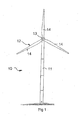
- Fig. 1 shows a schematic representation of a wind turbine 10.
- the wind turbine 10 has a tower 11 and a rotor 12, which includes three rotor blades 14 which are mounted on a rotor hub 13.
- the rotor 12 rotates in a conventional manner.
- power can be generated by a generator connected to the rotor 12 or to the rotor hub 13 and delivered to a consumer network.
- Fig. 2 schematically shows essential components of the wind turbine 10 according to the invention.
- An operating guide 15, which may also be referred to as a management device or management system, controls and / or regulates the operation of the wind turbine 10.
- a security monitoring 16 which is connected to a security chain 20 is.
- the safety chain 20 includes, for example, a vibration detector, a manual (emergency stop) switch and a speed switch relay.
- the safety chain 20 serves to shut down the wind power plant to a non-critical state in the presence of a safety-relevant event, for example, excessive vibration or actuation of the emergency stop switch by an operator.
- the security chain 20 can be designed as a hardware chain.
- the generator 23 is taken from the network 25 and the rotor shaft 9 or the fast shaft 22 braked, for example via the blade adjustment 18 or the mechanical brake 19 or Also, which is not shown, directly bypassing one or more control or regulating devices such as the blade adjustment 19.
- the safety monitoring 16 can also be configured such that it checks the operation management 15 for functionality.
- the security monitoring 16 is insofar preferably designed as a kind of watchdog.
- the operation management 15 'can as shown in dashed lines, include the security monitoring 16. It is then an operational management 15 'with integrated security monitoring 16.
- the operating guide 15, 15 ' is connected via corresponding electronic data lines with a controller 17 and the blade adjustment 18 and also with the mechanical brake 19.
- blade adjustment 18 is in particular an actuator understood, the for a blade adjustment of the rotor blades 14 provides.
- mechanical brake 19 is understood to mean an actuator which ensures that the mechanical brake 19 acts on the fast shaft 22 in this exemplary embodiment.
- the mechanical brake 19 can also act on the rotor shaft 9, which is not shown.
- Denoted by 26 is a data link which feeds a rotor blade angle or the rotor blade angle of the rotor blades 14 to the operating guide 15 or 15 '.
- Denoted at 30 is a data line which feeds an interference signal, which in this embodiment starts from electrical components 21, to the operational management 15 or 15 '.
- the operation of the wind turbine is as follows.
- the rotor 12 is rotated in accordance with the direction of rotation 29.
- This also rotates the rotor shaft 9, which rotates with a gear 24 in a ratio of, for example 1: 100, the fast shaft 22.
- an electrical voltage is generated in the generator 23, which is regulated in the electrical components 21, re-directed and / or converted into an AC voltage.
- a connection to the network 25 is provided, with which the consumers are supplied with voltage or electrical power.
- Wind Turbines System Design, Network Integration and Control by Siegfried Heier
- an extreme Windbö 31 When an extreme Windbö 31 occurs, it may be related occur with a load drop of the generator, so in particular an abrupt omission of the network load, for example by a converter, a generator, a transformer, a mains failure or the triggering of a safety chain that the speed of the rotor or the generator in very critical and reach high speeds, so that an abrupt deceleration is necessary, which can lead to severe fatigue of the material of the wind turbine or damage.
- the invention counteracts the fact that the rotor 12 or the rotor shaft 9 or correspondingly the fast shaft 22 is braked, for example, even exceeding a relatively low third speed limit via a relatively slow angle adjustment 28 when a corresponding interference signal occurs. Due to the relatively small angular displacement rate of less than 8.5 ° / s, in particular less than 6.5 ° / s, a low-load deceleration is initiated.
- the safety system 16, 20 causes a redundant for operational management Triggering of the braking devices and possibly an even stronger braking effect, for example, a blade adjustment with higher angular displacement rate and / or an application of a hydraulic brake with higher hydraulic pressure.
- the second speed limit is designed such that it is achieved even with load shedding of the generator only in such extreme gusts of wind that occur with a probability that is less than once in three months. In this particular embodiment is to be assumed by a gust of wind, which has a probability of occurrence of less than once a year.
- a simple implementation of a well-used security system comprising a security monitor 16 and a security chain 20 is described, for example, on pages 473 and 474 of the publication "Wind Energy Handbook" referred to above.
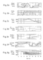
- FIG. 3a is a graph of wind speed versus time illustrating a common extreme operating condition, which may be calculated, for example, in Formula 5.1 on page 215 of the document Wind Energy Handbook, which is set forth in more detail above. It is a gust that occurs at the considered location with a probability of exactly once a year.
- Fig. 3d shows a graph of electric power in kW over time, showing two cases, namely the first case in which a load drop occurs at about 7.5 seconds, namely at the minimum of gust, and at about 9 seconds in comparison, which corresponds to a location that is approximately in the middle of the rising edge of the gust Fig. 3a is recognizable.
- the second case is the more critical case for the wind turbine and shown in dashed lines. For the safe design of a wind turbine, the Loss of load may occur at any time without creating a dangerous situation.
- Fig. 3b shows the angular displacement rate in ° / s of a rotor blade 14. It can be seen first that in both cases Fig. 3d due to the shape of the gust with associated lower wind speeds, the pitch rate is initially negative, ie, the rotor blades are placed in the wind, so that a higher torque can be generated. In the case of load drop, in both cases the angle adjustment rate is set relatively quickly by the operation management to a range of 5 ° / s. Minor dips in the angular displacement rate are due to a short-term overloading of the angle adjustment drives.
- the speed of the fast shaft 22 generated by the gust is in Fig. 3c shown.
- the ripple of the speed signal is due to the torsional vibration of the driveline described below.
- the speed increases to almost 2,200 revolutions per minute and in the more critical case (dashed line) it increases to just below 2,500 revolutions per minute.
- the second speed limit is preferably set to 2,500 revolutions per minute. Increasing the triggering speed for the safety chain to 2,500 revolutions per minute avoids triggering of the safety chain. Thus, the loads of the wind turbine can be significantly reduced.
- the usual release speed for the safety chain for wind turbines of the order of magnitude of 1.5 MW and greater is, for example, 2,400 revolutions per minute.
- Fig. 3e is the braking torque of the mechanical brake over time in a diagram shown schematically. It is recognizable, that for the first case (solid line), the mechanical brake is not activated because the first speed limit is not exceeded. Only for the second case (dashed line) is the mechanical brake activated when the first speed limit of 2,260 revolutions per minute is exceeded and it engages at approximately 11.5 seconds, and with a slight time delay, the mechanical brake begins to act.
- Fig. 3f is the tower foot bending moment in kNm over time for the two cases shown. It can be clearly seen that the second case (dashed) is more critical with respect to the tower foot bending moment. It can also be seen that in both cases a damped oscillation of the tower results from the gust.
- Fig. 3g the rotor torque is shown in kNm. Also in this case, the different cases are shown in solid and dashed lines. It can be seen that the driveline is stimulated by the sudden load drop in both cases to a strong torsional vibration, comparable to a preloaded torsion spring is suddenly released. In the second case (dashed line), the displacement of the vibration by the incident mechanical brake can be seen.
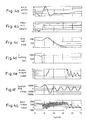
- FIGS. 4a to 4g a corresponding load case of a corresponding extreme Windbö (Personsbö) according to Fig. 4a at load drop of the generator according to Fig. 4d shown.
- a different process management on the one hand, a preferred inventive operation of the wind turbine (solid lines) and on the other hand a somewhat less preferred, however, inventive operation.
- This has, in contrast to the prior art already very low Blattver einsraten on, the very low values of 5 ° / s or 6 ° / s were set during emergency stop.
- this management has no first speed limit for triggering the brake on the operation management, but only the brake release via the safety device at a speed of 2,400 revolutions per minute. First, this dashed operation management process will be described.
- Fig. 4d It can be seen that the load drop is approximately in the middle of the rising flank of the gust of wind Fig. 4a takes place, ie in the critical area. In the less preferred embodiment, a blade displacement rate of 5 ° / sec is requested during load shedding. When the tripping speed exceeds 2,400 revolutions per minute (s. Fig. 4c ) an emergency stop is triggered via the safety device. An increased pitch rate of 6 ° / sec is required, but this can not be kept constant due to a tight angle adjustment. At the same time the mechanical brake is triggered, so that in this mode of operation a faster speed reduction results than in the preferred embodiment shown by solid lines. This results in relatively high Turmfußbiegemomente ( Fig.4f ).
- the invention thus relates to the design and operation of wind turbines, in particular for the DLC1.5 (Design Load Case for a one-year Millsbö with power failure).
- DLC1.5 Design Load Case for a one-year Millsbö with power failure.
- tower foot moments of up to 100,000 kNm (including safety factor) can occur.
- An increased aerodynamic thrust which is greater the higher and more dynamic the tower is, i. the lower the natural frequency of the tower, the momentum of the tower can be increased.
- the first speed limit is preferably selected so that in case of power failure or elimination of the network load without occurrence of a gust blade pitch sufficient to ensure safe operation without mechanical brake. This only occurs when, in addition, a wind buffet occurs at an unfavorable time.
- Increasing the first speed limit for example to 2,230 or 2,270 revolutions per minute results in only a slightly higher Turmfußbiegemoment compared to the case at 2,200 revolutions per minute, which is why this, as in FIG. 4 shown, may be advantageous for a simple parameterization of the operation management system or the operation management device, for example, if this speed limit already exists for other operations management procedures.
- a further reduction of the tower foot bending moment can be achieved by further minimizing the blade displacement rate, for example preferably at 4.5 ° / s or more preferably at 4 ° / s as in Fig. 4b shown.
- the second speed limit can be configured higher than usual in a 1.5 MW system by the invention, for example, to 2,570 revolutions per minute or even to 2,660 revolutions per minute.
- the mechanical brake which in Fig. 4e is shown, operated earlier than usual.
- a high blade displacement rate is avoided, for example, by using an unregulated adjustment directly via an accumulator.
- the driveline load is here, as in Fig. 4g recognizable, not significantly worse.
- the method is used to operate the wind turbine only at mean wind speeds greater than 9 m / s and less than about 20 m / s.
Landscapes
- Engineering & Computer Science (AREA)
- Life Sciences & Earth Sciences (AREA)
- Sustainable Development (AREA)
- Sustainable Energy (AREA)
- Chemical & Material Sciences (AREA)
- Combustion & Propulsion (AREA)
- Mechanical Engineering (AREA)
- General Engineering & Computer Science (AREA)
- Physics & Mathematics (AREA)
- Fluid Mechanics (AREA)
- Wind Motors (AREA)
Priority Applications (3)
| Application Number | Priority Date | Filing Date | Title |
|---|---|---|---|
| PL16173903T PL3112676T3 (pl) | 2006-01-11 | 2007-01-04 | Sposób eksploatacji elektrowni wiatrowej i elektrownia wiatrowa |
| DK16173903.2T DK3112676T3 (en) | 2006-01-11 | 2007-01-04 | PROCEDURE FOR OPERATING A WINDOW ENERGY INSTALLATION AND A WINDOW ENERGY INSTALLATION |
| EP16173903.2A EP3112676B1 (fr) | 2006-01-11 | 2007-01-04 | Procede de fonctionnement d'une eolienne et eolienne |
Applications Claiming Priority (2)
| Application Number | Priority Date | Filing Date | Title |
|---|---|---|---|
| DE102006001613A DE102006001613B4 (de) | 2006-01-11 | 2006-01-11 | Verfahren zum Betreiben einer Windenergieanlage und Windenergieanlage |
| EP07700184.0A EP1971772B1 (fr) | 2006-01-11 | 2007-01-04 | Procede de conduite d'un systeme a energie eolienne et systeme a energie eolienne |
Related Parent Applications (3)
| Application Number | Title | Priority Date | Filing Date |
|---|---|---|---|
| EP07700184.0A Division-Into EP1971772B1 (fr) | 2006-01-11 | 2007-01-04 | Procede de conduite d'un systeme a energie eolienne et systeme a energie eolienne |
| EP07700184.0A Division EP1971772B1 (fr) | 2006-01-11 | 2007-01-04 | Procede de conduite d'un systeme a energie eolienne et systeme a energie eolienne |
| EP07700184.0 Division | 2007-01-04 |
Related Child Applications (2)
| Application Number | Title | Priority Date | Filing Date |
|---|---|---|---|
| EP16173903.2A Division EP3112676B1 (fr) | 2006-01-11 | 2007-01-04 | Procede de fonctionnement d'une eolienne et eolienne |
| EP16173903.2A Division-Into EP3112676B1 (fr) | 2006-01-11 | 2007-01-04 | Procede de fonctionnement d'une eolienne et eolienne |
Publications (2)
| Publication Number | Publication Date |
|---|---|
| EP2535568A1 true EP2535568A1 (fr) | 2012-12-19 |
| EP2535568B1 EP2535568B1 (fr) | 2016-07-20 |
Family
ID=38170014
Family Applications (3)
| Application Number | Title | Priority Date | Filing Date |
|---|---|---|---|
| EP07700184.0A Not-in-force EP1971772B1 (fr) | 2006-01-11 | 2007-01-04 | Procede de conduite d'un systeme a energie eolienne et systeme a energie eolienne |
| EP16173903.2A Active EP3112676B1 (fr) | 2006-01-11 | 2007-01-04 | Procede de fonctionnement d'une eolienne et eolienne |
| EP12169956.5A Active EP2535568B1 (fr) | 2006-01-11 | 2007-01-04 | Procédé de fonctionnement d'une éolienne et éolienne |
Family Applications Before (2)
| Application Number | Title | Priority Date | Filing Date |
|---|---|---|---|
| EP07700184.0A Not-in-force EP1971772B1 (fr) | 2006-01-11 | 2007-01-04 | Procede de conduite d'un systeme a energie eolienne et systeme a energie eolienne |
| EP16173903.2A Active EP3112676B1 (fr) | 2006-01-11 | 2007-01-04 | Procede de fonctionnement d'une eolienne et eolienne |
Country Status (11)
| Country | Link |
|---|---|
| US (1) | US7939955B2 (fr) |
| EP (3) | EP1971772B1 (fr) |
| JP (1) | JP5084053B2 (fr) |
| KR (1) | KR101157608B1 (fr) |
| CN (1) | CN101371037B (fr) |
| CA (1) | CA2633927C (fr) |
| DE (1) | DE102006001613B4 (fr) |
| DK (3) | DK2535568T3 (fr) |
| ES (3) | ES2598678T3 (fr) |
| PL (1) | PL3112676T3 (fr) |
| WO (1) | WO2007082642A1 (fr) |
Cited By (1)
| Publication number | Priority date | Publication date | Assignee | Title |
|---|---|---|---|---|
| CN108374768A (zh) * | 2018-01-22 | 2018-08-07 | 佛山尉达科技有限公司 | 风力发电装置的制造方法 |
Families Citing this family (42)
| Publication number | Priority date | Publication date | Assignee | Title |
|---|---|---|---|---|
| US7692322B2 (en) * | 2004-02-27 | 2010-04-06 | Mitsubishi Heavy Industries, Ltd. | Wind turbine generator, active damping method thereof, and windmill tower |
| AT504818A1 (de) * | 2004-07-30 | 2008-08-15 | Windtec Consulting Gmbh | Triebstrang einer windkraftanlage |
| ES2553578T3 (es) | 2007-07-14 | 2015-12-10 | Vestas Wind Systems A/S | Control de rotor durante un procedimiento de parada de una turbina eólica |
| DE102007040834A1 (de) * | 2007-08-29 | 2009-03-05 | S.B. Patent Holding Aps | Verfahren zum Betreiben einer Windenergieanlage und Steuer- und Regeleinheit zur Ausführung des Verfahrens |
| DE102008012956B4 (de) | 2008-03-06 | 2011-06-30 | REpower Systems AG, 22297 | Blattwinkelverstellratengrenzwertanpassung |
| DE102008012957A1 (de) | 2008-03-06 | 2009-09-10 | Repower Systems Ag | Verfahren zum Betreiben einer Windenergieanlage und Windenergieanlage |
| ATE552421T1 (de) * | 2008-05-14 | 2012-04-15 | Alstom Wind Sl | Verfahren zur reduktion von torsionsschwingungen im antriebsstrang einer windturbine |
| CN101660493B (zh) * | 2008-08-29 | 2014-10-01 | 维斯塔斯风力系统有限公司 | 用于测试桨距系统故障的桨距控制系统 |
| ES2358711B1 (es) * | 2008-09-18 | 2012-03-23 | Gamesa Innovation & Technology, S.L. | Mã‰todo para parar un aerogenerador en dos etapas. |
| EP2362093B1 (fr) | 2009-01-22 | 2012-10-17 | Vestas Wind Systems A/S | Contrôle de rotor durant la procédure d'arrêt d'une éolienne |
| EP2256342B8 (fr) | 2009-05-28 | 2013-10-23 | Nordex Energy GmbH | Procédé de freinage d'urgence d'une éolienne et éolienne dotée d'un réglage de pale de rotor pour le freinage d'urgence |
| US7772713B2 (en) * | 2009-09-30 | 2010-08-10 | General Electric Company | Method and system for controlling a wind turbine |
| DE102009057062A1 (de) | 2009-12-04 | 2011-06-09 | Nordex Energy Gmbh | Verfahren zum Betrieb einer drehzahlgeregelten Windenergieanlage sowie eine solche Windenergieanlage |
| EP2339174A1 (fr) * | 2009-12-22 | 2011-06-29 | Siemens Aktiengesellschaft | Système de déclenchement de système d'urgence d'une éolienne |
| CN101718251B (zh) * | 2010-01-21 | 2012-10-31 | 李金芬 | 风力发电叶轮的捕风面可调叶片及其叶片的调整方法 |
| CN101922413A (zh) * | 2010-02-08 | 2010-12-22 | 国能风力发电有限公司 | 用于垂直轴风力发电机的制动方法及制动装置 |
| DE102010024566A1 (de) | 2010-06-10 | 2011-12-15 | Repower Systems Ag | Windenergieanlage und Verfahren zum Prüfen eines Drehzahlrelais einer Windenergieanlage |
| CN103443455B (zh) * | 2011-01-13 | 2016-08-24 | 维斯塔斯风力系统集团公司 | 测试风轮机的超速保护系统 |
| EP2479427A1 (fr) | 2011-01-24 | 2012-07-25 | Siemens Aktiengesellschaft | Procédé d'amortissement d'oscillations d'un entraînement dans une éolienne, éolienne et utilisation d'un dispositif de freinage |
| EP2712402B1 (fr) * | 2011-05-06 | 2020-12-23 | Seawind Ocean Technology Holding BV | Systèmes destinés à réduire au minimum le couple d'orientation nécessaire pour commander la puissance de sortie d'éoliennes bipales, à articulation de bascule qui commandent la puissance de sortie par orientation |
| DE102011079269A1 (de) * | 2011-07-15 | 2013-01-17 | Suzlon Energy Gmbh | Sicherheitskette und Verfahren zum Betreiben einer Windturbine |
| DE102011054211B3 (de) * | 2011-10-05 | 2013-01-10 | Kenersys Gmbh | Verfahren zum Betreiben einer Windenergieanlage und entsprechende Windenergieanlage |
| US9759192B2 (en) * | 2012-08-16 | 2017-09-12 | General Electric Company | System and method for braking a wind turbine rotor at an overspeed condition |
| ITMI20121666A1 (it) * | 2012-10-05 | 2014-04-06 | Wilic Sarl | Impianto eolico per la generazione di energia elettrica |
| DE102012218484A1 (de) * | 2012-10-10 | 2014-04-10 | Wobben Properties Gmbh | Verfahren zum Betreiben einer Windenergieanlage |
| US10024303B2 (en) | 2012-12-27 | 2018-07-17 | Mhi Vestas Offshore Wind A/S | Method and device for controlling floating body wind turbine power generating apparatus, and floating body wind turbine power generating apparatus |
| KR101258247B1 (ko) * | 2013-01-25 | 2013-04-25 | 윤양일 | 회전형 발전기의 운전 제어장치 |
| US9388792B2 (en) | 2013-03-15 | 2016-07-12 | Frontier Wind, Llc | Distributed control system |
| US9534584B2 (en) | 2013-06-13 | 2017-01-03 | Cooper Industries Holdings | Wind turbine electric generator with torque limiting brake |
| KR101454378B1 (ko) * | 2013-10-16 | 2014-10-23 | 삼성중공업 주식회사 | 풍력발전기의 피치 시스템에 대한 고장 시 비상 제어 방법 및 이에 적용되는 장치 |
| DK2886856T3 (da) * | 2013-12-20 | 2020-01-02 | Siemens Gamesa Renewable Energy As | Detektering af pitchvinkeljusteringsfejl |
| KR101637699B1 (ko) * | 2014-10-20 | 2016-07-07 | 두산중공업 주식회사 | 풍력 발전기 속도 제어 시스템 및 방법 |
| JP6462388B2 (ja) * | 2015-02-06 | 2019-01-30 | 株式会社日立製作所 | 風力発電装置 |
| EP3128170B1 (fr) | 2015-08-06 | 2018-02-28 | Nordex Energy GmbH | Éolienne avec entrainement azimutal |
| JP6463288B2 (ja) | 2016-02-26 | 2019-01-30 | 株式会社日立製作所 | 風力発電システムおよび風力発電システムの制御方法 |
| ES2937911T3 (es) * | 2017-12-14 | 2023-04-03 | Vestas Wind Sys As | Amortiguación de la torre durante la producción de energía de una turbina eólica |
| CN108488037B (zh) * | 2018-03-01 | 2019-07-19 | 北京金风科创风电设备有限公司 | 防飞车控制方法和装置、风力发电机组 |
| EP3623615A1 (fr) * | 2018-09-17 | 2020-03-18 | Siemens Gamesa Renewable Energy A/S | Réaction à un événement de survitesse |
| CN111396265B (zh) * | 2019-01-03 | 2023-02-03 | 新疆金风科技股份有限公司 | 一种风力发电机组的故障预测方法及装置 |
| JP7144369B2 (ja) * | 2019-07-10 | 2022-09-29 | 日立造船株式会社 | 燃料電池システム |
| CN113048019B (zh) * | 2019-12-27 | 2022-08-09 | 北京金风科创风电设备有限公司 | 阵风检测方法、阵风控制器和风力发电系统 |
| CN113864116B (zh) * | 2020-06-30 | 2022-11-08 | 新疆金风科技股份有限公司 | 风力发电机组的控制方法和设备 |
Citations (4)
| Publication number | Priority date | Publication date | Assignee | Title |
|---|---|---|---|---|
| DE19626402C1 (de) * | 1996-07-01 | 1997-07-24 | Aerodyn Energiesysteme Gmbh | Verfahren zum Blattverstellen |
| EP0942168A2 (fr) * | 1998-03-13 | 1999-09-15 | Tacke Windenergie GmbH | Dispositif de réglage du pas de l'hélice pour turbine éolienne |
| WO2001066940A1 (fr) * | 2000-03-08 | 2001-09-13 | Forskningscenter Risø | Procede d'utilisation d'une turbine |
| EP1612414A2 (fr) * | 2004-06-30 | 2006-01-04 | General Electric Company | Méthode et dispositif de réduction des charges sur le rotor d'une éolienne |
Family Cites Families (22)
| Publication number | Priority date | Publication date | Assignee | Title |
|---|---|---|---|---|
| US4160170A (en) | 1978-06-15 | 1979-07-03 | United Technologies Corporation | Wind turbine generator pitch control system |
| US4193005A (en) * | 1978-08-17 | 1980-03-11 | United Technologies Corporation | Multi-mode control system for wind turbines |
| DE19717059C1 (de) * | 1997-04-23 | 1998-07-09 | Aerodyn Eng Gmbh | Verfahren zum Verbringen einer Windkraftanlage in eine Parkstellung |
| DE10011393A1 (de) | 2000-03-09 | 2001-09-13 | Tacke Windenergie Gmbh | Regelungssystem für eine Windkraftanlage |
| DE10058076C2 (de) | 2000-11-23 | 2003-06-12 | Aloys Wobben | Verfahren zur Steuerung einer Windenergieanlage |
| JP2002315395A (ja) * | 2001-04-06 | 2002-10-25 | Mitsubishi Heavy Ind Ltd | 風力発電装置 |
| DE10137272A1 (de) * | 2001-07-31 | 2003-02-27 | Aloys Wobben | Frühwarnsystem für Windenergieanlagen |
| DE10140793A1 (de) | 2001-08-20 | 2003-03-06 | Gen Electric | Einrichtung zum Verstellen des Rotorblattes eines Rotors einer Windkraftanlage |
| CN1529051A (zh) * | 2003-10-08 | 2004-09-15 | 陈晓通 | 聚风式风力发电法及其大功率发电机组 |
| DE102004024564B4 (de) * | 2004-05-18 | 2006-03-30 | Nordex Energy Gmbh | Verfahren zur Steuerung und Regelung einer Windenergieanlage sowie Windenergieanlage |
| AT504818A1 (de) * | 2004-07-30 | 2008-08-15 | Windtec Consulting Gmbh | Triebstrang einer windkraftanlage |
| DE102004054608B4 (de) * | 2004-09-21 | 2006-06-29 | Repower Systems Ag | Verfahren zur Regelung einer Windenergieanlage und Windenergieanlage mit einem Rotor |
| DE102004056223B4 (de) * | 2004-11-17 | 2008-11-27 | Nordex Energy Gmbh | Vorrichtung und Verfahren zur Funktionsprüfung einer Windenergieanlage |
| US7476985B2 (en) | 2005-07-22 | 2009-01-13 | Gamesa Innovation & Technology, S.L. | Method of operating a wind turbine |
| US7355294B2 (en) * | 2006-05-22 | 2008-04-08 | General Electric Company | Method and system for wind turbine blade movement |
| US7677075B2 (en) * | 2006-09-29 | 2010-03-16 | General Electric Company | Methods and apparatus for evaluating sensors and/or for controlling operation of an apparatus that includes a sensor |
| US7709972B2 (en) * | 2007-08-30 | 2010-05-04 | Mitsubishi Heavy Industries, Ltd. | Wind turbine system for satisfying low-voltage ride through requirement |
| DE102008012957A1 (de) * | 2008-03-06 | 2009-09-10 | Repower Systems Ag | Verfahren zum Betreiben einer Windenergieanlage und Windenergieanlage |
| DE102008020154B4 (de) * | 2008-04-22 | 2011-04-28 | Repower Systems Ag | Verfahren zum Betreiben einer Windenergieanlage |
| US8008797B2 (en) * | 2009-02-13 | 2011-08-30 | Bernard Joseph Simon | System for converting wind power to electrcial power with transmission |
| US7763989B2 (en) * | 2009-07-07 | 2010-07-27 | General Electric Company | Method and apparatus for controlling the tip speed of a blade of a wind turbine |
| US8080891B2 (en) * | 2009-09-25 | 2011-12-20 | General Electric Company | Hybrid braking system and method |
-
2006
- 2006-01-11 DE DE102006001613A patent/DE102006001613B4/de not_active Expired - Fee Related
-
2007
- 2007-01-04 PL PL16173903T patent/PL3112676T3/pl unknown
- 2007-01-04 EP EP07700184.0A patent/EP1971772B1/fr not_active Not-in-force
- 2007-01-04 WO PCT/EP2007/000045 patent/WO2007082642A1/fr active Application Filing
- 2007-01-04 KR KR1020087018400A patent/KR101157608B1/ko active IP Right Grant
- 2007-01-04 ES ES12169956.5T patent/ES2598678T3/es active Active
- 2007-01-04 JP JP2008549814A patent/JP5084053B2/ja active Active
- 2007-01-04 CN CN2007800023800A patent/CN101371037B/zh not_active Expired - Fee Related
- 2007-01-04 ES ES07700184.0T patent/ES2476426T3/es active Active
- 2007-01-04 DK DK12169956.5T patent/DK2535568T3/en active
- 2007-01-04 US US12/160,511 patent/US7939955B2/en not_active Expired - Fee Related
- 2007-01-04 CA CA2633927A patent/CA2633927C/fr active Active
- 2007-01-04 EP EP16173903.2A patent/EP3112676B1/fr active Active
- 2007-01-04 EP EP12169956.5A patent/EP2535568B1/fr active Active
- 2007-01-04 DK DK16173903.2T patent/DK3112676T3/en active
- 2007-01-04 DK DK07700184.0T patent/DK1971772T3/da active
- 2007-01-04 ES ES16173903T patent/ES2718050T3/es active Active
Patent Citations (4)
| Publication number | Priority date | Publication date | Assignee | Title |
|---|---|---|---|---|
| DE19626402C1 (de) * | 1996-07-01 | 1997-07-24 | Aerodyn Energiesysteme Gmbh | Verfahren zum Blattverstellen |
| EP0942168A2 (fr) * | 1998-03-13 | 1999-09-15 | Tacke Windenergie GmbH | Dispositif de réglage du pas de l'hélice pour turbine éolienne |
| WO2001066940A1 (fr) * | 2000-03-08 | 2001-09-13 | Forskningscenter Risø | Procede d'utilisation d'une turbine |
| EP1612414A2 (fr) * | 2004-06-30 | 2006-01-04 | General Electric Company | Méthode et dispositif de réduction des charges sur le rotor d'une éolienne |
Non-Patent Citations (4)
| Title |
|---|
| "Windkraft Systemauslegung, Netzintegration und Regelung", February 2005 |
| BRADFORD S. LINSCOTT ET AL: "The Mod-2 Wind Turbine Development Project", 31 July 1981 (1981-07-31), pages 1 - 23, XP055034683, Retrieved from the Internet <URL:http://ntrs.nasa.gov/archive/nasa/casi.ntrs.nasa.gov/19810019068_1981019068.pdf> [retrieved on 20120803] * |
| TONY BURTON; DAVID SHARPE; NICK JENKINS; ERVIN BOSSANYI: "Wind Energy Handbook", November 2002, JOHN WILEY & SONS LTD., pages: 214 - 218 |
| VON TONY BURTON ET AL.: "Wind Energy Handbook", pages: 216 - 218 |
Cited By (1)
| Publication number | Priority date | Publication date | Assignee | Title |
|---|---|---|---|---|
| CN108374768A (zh) * | 2018-01-22 | 2018-08-07 | 佛山尉达科技有限公司 | 风力发电装置的制造方法 |
Also Published As
| Publication number | Publication date |
|---|---|
| EP3112676A1 (fr) | 2017-01-04 |
| CN101371037B (zh) | 2012-05-30 |
| CA2633927A1 (fr) | 2007-07-26 |
| ES2476426T3 (es) | 2014-07-14 |
| JP2009523208A (ja) | 2009-06-18 |
| DK1971772T3 (da) | 2014-07-28 |
| KR101157608B1 (ko) | 2012-06-19 |
| US7939955B2 (en) | 2011-05-10 |
| WO2007082642A1 (fr) | 2007-07-26 |
| DE102006001613A1 (de) | 2007-07-12 |
| CA2633927C (fr) | 2012-02-14 |
| EP1971772A1 (fr) | 2008-09-24 |
| JP5084053B2 (ja) | 2012-11-28 |
| EP1971772B1 (fr) | 2014-05-21 |
| DK2535568T3 (en) | 2016-11-14 |
| EP3112676B1 (fr) | 2018-12-26 |
| DK3112676T3 (en) | 2019-04-15 |
| DE102006001613B4 (de) | 2008-01-31 |
| ES2598678T3 (es) | 2017-01-30 |
| ES2718050T3 (es) | 2019-06-27 |
| EP2535568B1 (fr) | 2016-07-20 |
| US20090295161A1 (en) | 2009-12-03 |
| PL3112676T3 (pl) | 2019-07-31 |
| CN101371037A (zh) | 2009-02-18 |
| KR20080084846A (ko) | 2008-09-19 |
Similar Documents
| Publication | Publication Date | Title |
|---|---|---|
| EP1971772B1 (fr) | Procede de conduite d'un systeme a energie eolienne et systeme a energie eolienne | |
| EP2098725B1 (fr) | Procédé de fonctionnement d'une éolienne et éolienne | |
| EP2217805B1 (fr) | Dispositif de commande pour des installations éoliennes comportant un système de détection de panne de secteur | |
| DE10338127C5 (de) | Windenergieanlage mit einem Rotor | |
| DE60311896T2 (de) | Redundantes steuerungssystem zur verstellung der anstellwinkel der rotorblätter einer windkraftanlage | |
| EP2915999B1 (fr) | Réduction de la charge motrice dans une éolienne | |
| EP1548279A1 (fr) | Système de réglage pour une éolienne avec transmission hydrodynamique | |
| EP3265675B1 (fr) | Procédé pour faire fonctionner une éolienne | |
| WO2005031160A2 (fr) | Eolienne dotee d'un module de puissance reactive pour le support du reseau et procede associe | |
| EP2622214A1 (fr) | Procédé pour l'adaptation de la vitesse de rotation d'une installation d'énergie éolienne et installation d'énergie éolienne | |
| EP3489507B1 (fr) | Procédé et dispositif destinés au fonctionnement d'une éolienne | |
| DE102013206119A1 (de) | Windenergieanlage und Verfahren zum Betreiben einer Windenergieanlage | |
| EP2948678B1 (fr) | Procédé de réglage azimutal d'une éolienne, système de réglage azimutal et éolienne | |
| WO2020079059A1 (fr) | Procédé servant à faire fonctionner une éolienne en cas d'incident | |
| EP3165765B1 (fr) | Procédé et système de commande d'un angle d'attaque d'une pale de rotor et éolienne et procédé de fonctionnement d'une éolienne | |
| EP3810924A1 (fr) | Fonctionnement à puissance réduite d'une éolienne | |
| WO2020109483A1 (fr) | Procédé permettant de faire fonctionner une éolienne |
Legal Events
| Date | Code | Title | Description |
|---|---|---|---|
| PUAI | Public reference made under article 153(3) epc to a published international application that has entered the european phase |
Free format text: ORIGINAL CODE: 0009012 |
|
| 17P | Request for examination filed |
Effective date: 20120530 |
|
| AC | Divisional application: reference to earlier application |
Ref document number: 1971772 Country of ref document: EP Kind code of ref document: P |
|
| AK | Designated contracting states |
Kind code of ref document: A1 Designated state(s): AT BE BG CH CY CZ DE DK EE ES FI FR GB GR HU IE IS IT LI LT LU LV MC NL PL PT RO SE SI SK TR |
|
| 17Q | First examination report despatched |
Effective date: 20140430 |
|
| RAP1 | Party data changed (applicant data changed or rights of an application transferred) |
Owner name: REPOWER SYSTEMS SE |
|
| RAP1 | Party data changed (applicant data changed or rights of an application transferred) |
Owner name: SENVION SE |
|
| RAP1 | Party data changed (applicant data changed or rights of an application transferred) |
Owner name: SENVION GMBH |
|
| GRAP | Despatch of communication of intention to grant a patent |
Free format text: ORIGINAL CODE: EPIDOSNIGR1 |
|
| INTG | Intention to grant announced |
Effective date: 20160223 |
|
| GRAS | Grant fee paid |
Free format text: ORIGINAL CODE: EPIDOSNIGR3 |
|
| GRAA | (expected) grant |
Free format text: ORIGINAL CODE: 0009210 |
|
| AC | Divisional application: reference to earlier application |
Ref document number: 1971772 Country of ref document: EP Kind code of ref document: P |
|
| AK | Designated contracting states |
Kind code of ref document: B1 Designated state(s): AT BE BG CH CY CZ DE DK EE ES FI FR GB GR HU IE IS IT LI LT LU LV MC NL PL PT RO SE SI SK TR |
|
| REG | Reference to a national code |
Ref country code: GB Ref legal event code: FG4D Free format text: NOT ENGLISH |
|
| REG | Reference to a national code |
Ref country code: CH Ref legal event code: EP |
|
| REG | Reference to a national code |
Ref country code: IE Ref legal event code: FG4D Free format text: LANGUAGE OF EP DOCUMENT: GERMAN |
|
| REG | Reference to a national code |
Ref country code: AT Ref legal event code: REF Ref document number: 814324 Country of ref document: AT Kind code of ref document: T Effective date: 20160815 |
|
| REG | Reference to a national code |
Ref country code: DE Ref legal event code: R096 Ref document number: 502007014961 Country of ref document: DE |
|
| REG | Reference to a national code |
Ref country code: LT Ref legal event code: MG4D |
|
| REG | Reference to a national code |
Ref country code: DK Ref legal event code: T3 Effective date: 20161111 |
|
| REG | Reference to a national code |
Ref country code: NL Ref legal event code: MP Effective date: 20160720 |
|
| REG | Reference to a national code |
Ref country code: FR Ref legal event code: PLFP Year of fee payment: 11 |
|
| REG | Reference to a national code |
Ref country code: ES Ref legal event code: FG2A Ref document number: 2598678 Country of ref document: ES Kind code of ref document: T3 Effective date: 20170130 |
|
| PG25 | Lapsed in a contracting state [announced via postgrant information from national office to epo] |
Ref country code: IT Free format text: LAPSE BECAUSE OF FAILURE TO SUBMIT A TRANSLATION OF THE DESCRIPTION OR TO PAY THE FEE WITHIN THE PRESCRIBED TIME-LIMIT Effective date: 20160720 Ref country code: LT Free format text: LAPSE BECAUSE OF FAILURE TO SUBMIT A TRANSLATION OF THE DESCRIPTION OR TO PAY THE FEE WITHIN THE PRESCRIBED TIME-LIMIT Effective date: 20160720 Ref country code: FI Free format text: LAPSE BECAUSE OF FAILURE TO SUBMIT A TRANSLATION OF THE DESCRIPTION OR TO PAY THE FEE WITHIN THE PRESCRIBED TIME-LIMIT Effective date: 20160720 Ref country code: NL Free format text: LAPSE BECAUSE OF FAILURE TO SUBMIT A TRANSLATION OF THE DESCRIPTION OR TO PAY THE FEE WITHIN THE PRESCRIBED TIME-LIMIT Effective date: 20160720 Ref country code: IS Free format text: LAPSE BECAUSE OF FAILURE TO SUBMIT A TRANSLATION OF THE DESCRIPTION OR TO PAY THE FEE WITHIN THE PRESCRIBED TIME-LIMIT Effective date: 20161120 |
|
| PG25 | Lapsed in a contracting state [announced via postgrant information from national office to epo] |
Ref country code: GR Free format text: LAPSE BECAUSE OF FAILURE TO SUBMIT A TRANSLATION OF THE DESCRIPTION OR TO PAY THE FEE WITHIN THE PRESCRIBED TIME-LIMIT Effective date: 20161021 Ref country code: PL Free format text: LAPSE BECAUSE OF FAILURE TO SUBMIT A TRANSLATION OF THE DESCRIPTION OR TO PAY THE FEE WITHIN THE PRESCRIBED TIME-LIMIT Effective date: 20160720 Ref country code: SE Free format text: LAPSE BECAUSE OF FAILURE TO SUBMIT A TRANSLATION OF THE DESCRIPTION OR TO PAY THE FEE WITHIN THE PRESCRIBED TIME-LIMIT Effective date: 20160720 Ref country code: PT Free format text: LAPSE BECAUSE OF FAILURE TO SUBMIT A TRANSLATION OF THE DESCRIPTION OR TO PAY THE FEE WITHIN THE PRESCRIBED TIME-LIMIT Effective date: 20161121 Ref country code: LV Free format text: LAPSE BECAUSE OF FAILURE TO SUBMIT A TRANSLATION OF THE DESCRIPTION OR TO PAY THE FEE WITHIN THE PRESCRIBED TIME-LIMIT Effective date: 20160720 |
|
| REG | Reference to a national code |
Ref country code: DE Ref legal event code: R097 Ref document number: 502007014961 Country of ref document: DE |
|
| PG25 | Lapsed in a contracting state [announced via postgrant information from national office to epo] |
Ref country code: RO Free format text: LAPSE BECAUSE OF FAILURE TO SUBMIT A TRANSLATION OF THE DESCRIPTION OR TO PAY THE FEE WITHIN THE PRESCRIBED TIME-LIMIT Effective date: 20160720 Ref country code: EE Free format text: LAPSE BECAUSE OF FAILURE TO SUBMIT A TRANSLATION OF THE DESCRIPTION OR TO PAY THE FEE WITHIN THE PRESCRIBED TIME-LIMIT Effective date: 20160720 |
|
| PLBE | No opposition filed within time limit |
Free format text: ORIGINAL CODE: 0009261 |
|
| STAA | Information on the status of an ep patent application or granted ep patent |
Free format text: STATUS: NO OPPOSITION FILED WITHIN TIME LIMIT |
|
| PG25 | Lapsed in a contracting state [announced via postgrant information from national office to epo] |
Ref country code: BG Free format text: LAPSE BECAUSE OF FAILURE TO SUBMIT A TRANSLATION OF THE DESCRIPTION OR TO PAY THE FEE WITHIN THE PRESCRIBED TIME-LIMIT Effective date: 20161020 Ref country code: CZ Free format text: LAPSE BECAUSE OF FAILURE TO SUBMIT A TRANSLATION OF THE DESCRIPTION OR TO PAY THE FEE WITHIN THE PRESCRIBED TIME-LIMIT Effective date: 20160720 Ref country code: SK Free format text: LAPSE BECAUSE OF FAILURE TO SUBMIT A TRANSLATION OF THE DESCRIPTION OR TO PAY THE FEE WITHIN THE PRESCRIBED TIME-LIMIT Effective date: 20160720 Ref country code: BE Free format text: LAPSE BECAUSE OF NON-PAYMENT OF DUE FEES Effective date: 20170131 |
|
| 26N | No opposition filed |
Effective date: 20170421 |
|
| PG25 | Lapsed in a contracting state [announced via postgrant information from national office to epo] |
Ref country code: SI Free format text: LAPSE BECAUSE OF FAILURE TO SUBMIT A TRANSLATION OF THE DESCRIPTION OR TO PAY THE FEE WITHIN THE PRESCRIBED TIME-LIMIT Effective date: 20160720 |
|
| REG | Reference to a national code |
Ref country code: CH Ref legal event code: PL |
|
| PG25 | Lapsed in a contracting state [announced via postgrant information from national office to epo] |
Ref country code: MC Free format text: LAPSE BECAUSE OF FAILURE TO SUBMIT A TRANSLATION OF THE DESCRIPTION OR TO PAY THE FEE WITHIN THE PRESCRIBED TIME-LIMIT Effective date: 20160720 |
|
| PG25 | Lapsed in a contracting state [announced via postgrant information from national office to epo] |
Ref country code: CH Free format text: LAPSE BECAUSE OF NON-PAYMENT OF DUE FEES Effective date: 20170131 Ref country code: LI Free format text: LAPSE BECAUSE OF NON-PAYMENT OF DUE FEES Effective date: 20170131 |
|
| REG | Reference to a national code |
Ref country code: IE Ref legal event code: MM4A |
|
| PG25 | Lapsed in a contracting state [announced via postgrant information from national office to epo] |
Ref country code: LU Free format text: LAPSE BECAUSE OF NON-PAYMENT OF DUE FEES Effective date: 20170104 |
|
| REG | Reference to a national code |
Ref country code: FR Ref legal event code: PLFP Year of fee payment: 12 |
|
| REG | Reference to a national code |
Ref country code: BE Ref legal event code: MM Effective date: 20170131 |
|
| PG25 | Lapsed in a contracting state [announced via postgrant information from national office to epo] |
Ref country code: IE Free format text: LAPSE BECAUSE OF NON-PAYMENT OF DUE FEES Effective date: 20170104 |
|
| REG | Reference to a national code |
Ref country code: AT Ref legal event code: MM01 Ref document number: 814324 Country of ref document: AT Kind code of ref document: T Effective date: 20170104 |
|
| PG25 | Lapsed in a contracting state [announced via postgrant information from national office to epo] |
Ref country code: AT Free format text: LAPSE BECAUSE OF NON-PAYMENT OF DUE FEES Effective date: 20170104 |
|
| PG25 | Lapsed in a contracting state [announced via postgrant information from national office to epo] |
Ref country code: HU Free format text: LAPSE BECAUSE OF FAILURE TO SUBMIT A TRANSLATION OF THE DESCRIPTION OR TO PAY THE FEE WITHIN THE PRESCRIBED TIME-LIMIT; INVALID AB INITIO Effective date: 20070104 |
|
| PG25 | Lapsed in a contracting state [announced via postgrant information from national office to epo] |
Ref country code: CY Free format text: LAPSE BECAUSE OF NON-PAYMENT OF DUE FEES Effective date: 20160720 |
|
| PG25 | Lapsed in a contracting state [announced via postgrant information from national office to epo] |
Ref country code: TR Free format text: LAPSE BECAUSE OF FAILURE TO SUBMIT A TRANSLATION OF THE DESCRIPTION OR TO PAY THE FEE WITHIN THE PRESCRIBED TIME-LIMIT Effective date: 20160720 |
|
| REG | Reference to a national code |
Ref country code: DE Ref legal event code: R081 Ref document number: 502007014961 Country of ref document: DE Owner name: SIEMENS GAMESA RENEWABLE ENERGY SERVICE GMBH, DE Free format text: FORMER OWNER: SENVION GMBH, 22297 HAMBURG, DE |
|
| PGFP | Annual fee paid to national office [announced via postgrant information from national office to epo] |
Ref country code: FR Payment date: 20230123 Year of fee payment: 17 Ref country code: ES Payment date: 20230216 Year of fee payment: 17 Ref country code: DK Payment date: 20230123 Year of fee payment: 17 |
|
| PGFP | Annual fee paid to national office [announced via postgrant information from national office to epo] |
Ref country code: GB Payment date: 20230124 Year of fee payment: 17 Ref country code: DE Payment date: 20230119 Year of fee payment: 17 |
|
| REG | Reference to a national code |
Ref country code: GB Ref legal event code: 732E Free format text: REGISTERED BETWEEN 20230727 AND 20230802 |