EP2534929B2 - Presence detection system and lighting system comprising such system - Google Patents
Presence detection system and lighting system comprising such system Download PDFInfo
- Publication number
- EP2534929B2 EP2534929B2 EP11706345.3A EP11706345A EP2534929B2 EP 2534929 B2 EP2534929 B2 EP 2534929B2 EP 11706345 A EP11706345 A EP 11706345A EP 2534929 B2 EP2534929 B2 EP 2534929B2
- Authority
- EP
- European Patent Office
- Prior art keywords
- zone
- movement
- detected
- area
- zones
- Prior art date
- Legal status (The legal status is an assumption and is not a legal conclusion. Google has not performed a legal analysis and makes no representation as to the accuracy of the status listed.)
- Active
Links
Images

Classifications
-
- H—ELECTRICITY
- H05—ELECTRIC TECHNIQUES NOT OTHERWISE PROVIDED FOR
- H05B—ELECTRIC HEATING; ELECTRIC LIGHT SOURCES NOT OTHERWISE PROVIDED FOR; CIRCUIT ARRANGEMENTS FOR ELECTRIC LIGHT SOURCES, IN GENERAL
- H05B47/00—Circuit arrangements for operating light sources in general, i.e. where the type of light source is not relevant
- H05B47/10—Controlling the light source
- H05B47/155—Coordinated control of two or more light sources
-
- H—ELECTRICITY
- H05—ELECTRIC TECHNIQUES NOT OTHERWISE PROVIDED FOR
- H05B—ELECTRIC HEATING; ELECTRIC LIGHT SOURCES NOT OTHERWISE PROVIDED FOR; CIRCUIT ARRANGEMENTS FOR ELECTRIC LIGHT SOURCES, IN GENERAL
- H05B47/00—Circuit arrangements for operating light sources in general, i.e. where the type of light source is not relevant
- H05B47/10—Controlling the light source
- H05B47/105—Controlling the light source in response to determined parameters
- H05B47/115—Controlling the light source in response to determined parameters by determining the presence or movement of objects or living beings
- H05B47/13—Controlling the light source in response to determined parameters by determining the presence or movement of objects or living beings by using passive infrared detectors
-
- Y—GENERAL TAGGING OF NEW TECHNOLOGICAL DEVELOPMENTS; GENERAL TAGGING OF CROSS-SECTIONAL TECHNOLOGIES SPANNING OVER SEVERAL SECTIONS OF THE IPC; TECHNICAL SUBJECTS COVERED BY FORMER USPC CROSS-REFERENCE ART COLLECTIONS [XRACs] AND DIGESTS
- Y02—TECHNOLOGIES OR APPLICATIONS FOR MITIGATION OR ADAPTATION AGAINST CLIMATE CHANGE
- Y02B—CLIMATE CHANGE MITIGATION TECHNOLOGIES RELATED TO BUILDINGS, e.g. HOUSING, HOUSE APPLIANCES OR RELATED END-USER APPLICATIONS
- Y02B20/00—Energy efficient lighting technologies, e.g. halogen lamps or gas discharge lamps
- Y02B20/40—Control techniques providing energy savings, e.g. smart controller or presence detection
Definitions
- the invention relates to a presence detection system for detecting a presence of an object, particularly a person or an animal, within an area having a plurality of detection zones.
- the system comprises a movement detection device for detecting a movement of the object.
- the invention also relates to a method for detecting a presence of an object, and to a lighting system that comprises the presence detection system.
- the ultrasound sensor in combination with passive infrared sensor, is relatively expensive.
- U.S. patent 6,909,921 B1 discloses an occupancy sensor and method for a home automation system and describes various types of sensors, including entry/exit sensors, room motion sen-sors, spot sensors, and house status sensors. Further, a central controller is described that communicates with the sensors. A plurality of room states can be assigned to each room of a house, which dictate how controlled objects are controlled by the central controller. Further, the sensitivity of the room occupancy sensors is automatically adjusted based upon tempera-ture measurements, and the number and timing of occupancy detections.
- the invention is defined by the independent claims.
- the dependent claims define advantageous embodiments.
- a presence detection system for detecting a presence of an object, particularly a person or an animal, within an area having a plurality of detection zones, comprises a movement detection device for detecting a movement of the object in said area, wherein said movement detection device is configured for zone-wise detecting a movement of the object in said plurality of detection zones.
- the system comprises an electronic processing device for storing information relating to a position of the object in a zone-wise way, based on the movement of the object, detected by the movement detection device.
- the electronic processing device is configured for determining, in a zone-wise way, the presence of the object within the area based on a detected movement and stored information relating to the position of the object in a zone-wise way.
- the system according to the invention solves the problem of the prior art since no high sensitive sensor in combination with the passive infrared sensor is needed. Instead, the presence of the object is based on detected movement of the object and stored information relating to the position of the object, thus not requiring additional sensors and also not requiring constant and highly sensitive presence detection in the area.
- An embodiment of the system according to the invention has the feature that the area is situated in a room.
- the room may be e.g. an office, a room in a house, a warehouse or a shop.
- An embodiment of the system according to the invention has the feature that the area is an outdoor area and the object is a vehicle, in particular a car.
- the presence detection system is used for determining the presence of the car in the outdoor area which outdoor area can be in a neighborhood of a house.
- An embodiment of the system according to the invention has the feature that the movement detection device comprises sensors, wherein each zone has a dedicated sensor.
- An advantage of this embodiment is that each of the sensors scanning one of the areas can be independently configured.
- An embodiment of the system according to the invention has the feature that the movement detection device comprises a sensor, wherein the zones are scanned by the sensor one by one.
- the movement detection device comprises a sensor, wherein the zones are scanned by the sensor one by one.
- An embodiment of the system according to the invention has the feature that at least one of sensors is constituted by an ultrasound sensor or an array of ultrasound sensors or a sound sensor or a radar-based sensor or a passive infrared sensor or an optical sensor.
- the most appropriate sensor is selected.
- the system according to the invention has the feature that the area comprises a passage.
- the zones include at least two zones, i.e. a first zone covering the passage and a second zone adjacent to the first zone.
- the presence of the object is determined from a first moment in time when a movement in the first zone is detected.
- the presence of the object is also determined when the movement in one of the other zones is detected.
- a non-presence of the object is determined when a movement from the second zone to the first zone is detected and thereafter no movement in the first zone is detected for a predetermined period of time.
- Choosing the predetermined period of time can be dependent on the purpose of the system. For example, the system can allow choosing the predetermined period of time in a range from 1 to 15 minutes. However, in principle an arbitrary length of such a period is possible.
- the presence detection result of the presence detection system is used as an input for a switch for switching on and off supply of electrical energy of a device when the person's presence or non presence is determined respectively.
- a lower predetermined period of time will save more electrical energy compared to a higher predetermined period of time.
- a person could be annoyed if switching off the device is too early.
- An embodiment of the system according to the invention has the feature that the movement detection device is operable at a first sensitivity level and a second sensitivity level, wherein the second sensitivity level is higher than the first sensitivity level.
- the zones are scanned with the first sensitivity level when the object in the relevant zone is not detected and the zone is scanned with the second sensitivity level when the object in said zone is detected.
- An advantage of this embodiment is that only areas where the person's presence is detected will be scanned with a higher sensitivity. It is an objective of the invention to detect even small movements, for example a person moving a shoulder or typing, in these areas and not to detect such small movements in other areas. Consequently, the probability of false presence detection is decreased since certain other areas will be scanned with a lower sensitivity. That means that e.g. a plant's leaf movement in other areas will not be detected.
- An embodiment of the system according to the invention has the feature that the system comprises a self-learning means for determining a zone covering the passage of the area based on an observation where the object presence detection always starts.
- An advantage of this embodiment is that the system does not need to be extensively configured. Instead, the system will be able to determine itself the zone where the passage is located. Namely that is the zone where the movement is detected first since that is the zone where the person enters the area.
- the invention also relates to a method defined in claim 6 for detecting a presence of an object, particularly a person or an animal, within an area having a plurality of detection zones.
- the method comprises the step of detecting a movement of the object in one of the zones by a movement detection device.
- the method comprises also the steps of storing information relating to a position of the object in a zone-wise way by an electronic processing device based on a detected movement of the object, and determining the presence of the object within the area based on a detected and stored information relating to the position of the object in a zone-wise way by said electronic processing device.
- the method according to the invention has the feature that the area comprises a passage, wherein the zones include at least a first zone covering the passage and a second zone adjacent to the first zone.
- the step of determining the presence of the object comprises determining the presence of the object from a first moment in time when a movement in the first zone is detected, determining the presence of the object when the movement in the one of the other zones is detected, and detecting a non-presence of the object when a movement from the second zone to the first zone is detected and thereafter no movement in the first zone is detected for a predetermined period of time.
- the method also allows ignoring of movements detected in a zone different than the first zone when there has not been detected any movement in the first zone.
- the method allows ignoring of movements that start and remain in a certain zone, including people detected in the first zone but not entering the room and thus not passing into the second zone. In this case an optimal positioning of the first zone lies partially outside the room.
- An embodiment of the method according to the invention has the feature that at least one of detection zones can be beyond the area.
- An advantage of this embodiment is that an object will be detected before entering the area, i.e. when the object is approaching the area.
- the invention also relates to a lighting system, comprising the presence detection system according to the invention, wherein the presence detection system initiates switching-on of a light of the lighting system when the person's presence is determined and the presence detection system initiates switching-off of the light of the lighting system when the person's non-presence is detected.
- a lighting system comprising the presence detection system according to the invention, wherein the presence detection system initiates switching-on of a light of the lighting system when the person's presence is determined and the presence detection system initiates switching-off of the light of the lighting system when the person's non-presence is detected.
- the presence detection system can also be used in or combined with e.g. a sound system for generating a sound signal in presence or absence of a person or an alarm system for generating a silent or loud alarm signal in presence or absence of a person.
- the presence detection system according to the invention can also be used as a part of a system for opening a door of an area based on the presence detection.
- the presence detection system according to the invention can also be used as a part of a system for monitoring an object.
- Stored information relating to the position of the object in a zone-wise way can be used in such monitoring system.
- a first embodiment of the invention is shown in Fig. 1 .
- a presence detection system 1 is meant and configured for detecting a presence of an object 3, in particular a living being 3, within an area 5.
- the object 3 can be a person or an animal.
- the object can be also a vehicle, in particular a car, in case that the area is an outdoor area.
- the area 5 is divided in 4 detection zones 9A;9B;9C;9D which zones together fully cover the area.
- the area can be covered with any number of zones. The zones do not need to overlap. The set of zones may leave some parts of the area uncovered.
- the system comprises a movement detection device 11A;11B;11C;11D for detecting a movement of the object.
- the movement detection device comprises sensors 11A;11B;11C;11D.
- Each zone 9A;9B;9C;9D has a dedicated sensor 11A;11B;11C;11D respectively.
- the area 5 can be a room, office, shop or any other suitable space. If the object is an animal, the area could be a space where the animal lives. If the object is a vehicle, the area can be for example an outdoor area close to a garage where the vehicle is parked.
- the sensor 11 can be any movement detection sensor known in the art.
- the senor can be an ultrasound sensor or an array of ultrasound sensors or a sound sensor or a radar-based sensor or a passive infrared sensor or an optical sensor.
- the presence detection system further comprises an electronic processing device 13 for storing information relating to a position of the object in a zone-wise way based on a detected movement of the object.
- Suitable electronic processing devices to be used for this purpose are known in the art.
- the electronic processor device could be a microprocessor or a personal computer, like a device running adequate software, i.e. a program.
- the electronic processing device receives the detection signals from the sensors 11;11B;11C;11D.
- the detection signal can be a binary signal, wherein for example the binary signal having the value of a logical 1 means that the presence of the object is detected and the value of a logical 0 means that the sensor does not detect the presence of the object.
- Signals received from the sensors can be for example stored as data by the electronic processing device in a database 15.
- the electronic processing device is configured for determining the presence of the object within the area based on detected movement of the object and stored information, i.e. the data from the database 15, relating to the position of the object in a zone-wise way, i.e. zone by zone.
- the sensor 11A will detect the person 3 in the area 5, for example the room 5, in the zone 9A and the electronic processing device 13 will store that information into the database 15. If the person 3 later moves from zone 9A into zone 9B, the sensor 11B will detect the presence of the person in the zone 9B. The electronic processing device 13 will store this new information into the database 15. If during a next period of time nothing is detected by sensors 9A and 9C and also nothing is detected by sensor 9B because the person is not making any major movement, the electronic processing device 13 will determine i.e. conclude the presence of the person 3 in the room 5 since according to the concrete configuration it is obvious that the person can leave the zone 9B only via the zone 9A or the zone 9C. So, if nothing is detected by respective sensors 11A and 11C the electronic processing device concludes that the person stays in the zone 9B.
- Fig. 1 also shows that room 5 comprises a passage 7, in particular a door 7.
- the first zone 9A covers the door 7. So, in this concrete example the person 3 will be detected for the first time in the zone 9A when the person enters the room 5 via the door 7. The presence will be concluded also when the movement in the one of the other zones 9B;9C;9D is detected.
- the person can move through the room and depending on the person's position at least one of the sensors 11A;11B;11C;11D will detect the person.
- the adjacent zones, for example 9A and 9B are partly overlapping each other assuring that the whole room 5 is covered by the sensors 11A;11B;11C;11D.
- the person's non-presence will be concluded when a movement from the second zone 9B to the first zone 9A by the respective sensors 11B and 11A is detected and thereafter no movement in the first zone 9A by the sensor 11A is detected for a predetermined period of time.
- Said predetermined period of time can be set according to the concrete application of the presence detection system.
- the predetermined period of time can be between 1 to 15 minutes for an office room wherein the presence detection system is used for switching light.
- the person working in that office room can set desired value for the predetermined period of time. For example someone could like that the light is switched off after one minute after leaving the office room in order to save electrical energy. Someone else, who leaves frequently the office room for relatively short period of time between 3-5 minutes, could desire to switch lights off after 10 minutes, and so on.
- the movement detection device i.e. sensors 11A;11B;11C;11D can be operable at a first sensitivity level and a second sensitivity level.
- the second sensitivity level is higher than the first sensitivity level.
- the zone 9A will be scanned with the higher sensitivity level and the zones 9B, 9C and 9D will be scanned with the lower sensitivity level.
- the lower sensitivity level is chosen in such way that will for sure detect the person walking but it will not detect a movement of the plant's blade. So, the false presence detection in the zones 9B, 9C and 9D is significantly reduced.
- the presence detection system 1 can further comprise a self-learning means for determining a zone 9A covering door 7 in the room 5 based on an observation where the object's presence detection always starts.
- a self-learning means can be implemented by a software program running on the electronic processing device. This program will follow where zone wise the person's presence is concluded for the first time and where zone wise the person's non-presence is concluded. In case of only one door in the room these two zones should be the same zone, which is in example presented in Fig. 1 the zone 9A.
- the presence detection system 1 can be a part of a lighting system 17.
- a lighting system includes a light source 19, for example a light bulb.
- the presence detection system can be configured to initiates switching-on of the light when the person's presence is determined and to initiates switching-off of the light when the person's non-presence is detected.
- Fig. 2 schematically shows a second exemplary embodiment of the presence detection system according to the invention.
- the difference with respect to Fig. 1 is that the sensors 11A;11B;11C;11D are located together, in this concrete example of Fig.2 in the upper left corner of the room. Any other position, for example at the ceiling in the middle of the room, is possible.
- the overlapping of the zones 9A;9B;9C;9D can be different with respect to Fig. 1 . This is dependent on the position of the sensor.
- the sensor can be constituted by discrete sensors mounted next to each other for example on a printed circuit board or by discrete sensors mounted in a package together.
- the sensor can also be an integrated sensor array, wherein several elements are designed in the array.
- the integrated sensor array can be realized in a silicon substrate, making use of semiconductor and micromachined technologies.
- the integrated sensor array can also be realized on other carriers such as glass, ceramic or polymer.
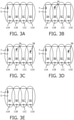
- Fig. 3A-3E schematically show a third exemplary embodiment of the system according to the invention, wherein two persons 3A and 3B are entering and leaving the room 5.
- the presence detection system is able to detect the presence of more than one person.
- Figs. 3A, 3B, 3C, 3D and 3E represent consecutive moments in time.
- FIG. 3B The next moment in time is shown by Fig. 3B .
- the person 3A first entered the room 5 and walked to the zone 9B.
- the presence detection system will consequently:
- FIG. 3C The next moment in time is shown by Fig. 3C .
- the person 3B entered the room 5 and walked to the zone 9D.
- the presence detection system will consequently:
- the presence detection system will conclude the presence of two persons 3A and 3B in the zones 9B and 9D respectively.
- Fig. 3D The next moment in time is shown by Fig. 3D .
- the person 3A left the room 5 via door 7.
- the presence detection system will receive the presence detection signal from the sensor 11A and not any more from the sensor 11B.
- the presence detection system will not receive the presence detection signal from the sensor anymore.
- the presence detection system will conclude that the person 3A left the room.
- Fig. 3E The next moment in time is shown by Fig. 3E .
- the person 3B left the room 5 via door 7.
- the presence detection system will receive the presence detection signal from the sensor 11C and not any more from the sensor 11D.
- the presence detection system will receive the presence detection signal from the sensor 11B and not any more from the sensor 11C.
- the presence detection system will receive the presence detection signal from the sensor 11A and not any more from the sensor 11B.
- the presence detection system will not receive the presence detection signal from the sensor anymore. After a predetermined period of time the presence detection system will conclude that the person 3B left the room.
- Fig. 3E The next moment in time is shown in Fig. 3E where no person is present in the room 5.
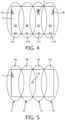
- Fig. 4 schematically shows a fourth exemplary embodiment of the system according to the invention wherein the area 5 comprises two passages 7A;7B i.e. doors. Obviously the person 3 can enter and leave the room via any one of these two doors.
- the presence detection can start either in the zone 9A or in the zone 9D.
- the person 3 entering the room 5 via the door 7A will be detected by sensor 11A in the zone 9A.
- the person walking to the area 9B and further to the area 9C will be detected by the sensors 11B and 11C respectively.
- the person's non-presence will be concluded in two ways.
- the first way when a movement from the second zone 9B to the first zone 9A by the respective sensors 11B and 11A is detected and thereafter no movement in the first zone 9A by the sensor 11A is detected for a first predetermined period of time.
- the second way when the movement from the third zone 9C to the fourth zone 9D by the respective sensors 11C and 11D is detected and thereafter no movement in the fourth zone 9D by the sensor 11D is detected for a second predetermined period of time.
- the first predetermined period of time and the second predetermined period of time can be the same or can be different depending on concrete requirements. If the concrete example shown in Fig.
- Fig. 5 schematically shows a fifth exemplary embodiment of the presence detecting system according to the invention with an area 5 with four zones 9A;9B;9C;9D wherein a single sensor 11E is used for the presence detection in each one of the four zones.
- the presence is sensed in one of the four zones at the time.
- the sensor 11E sense the presence in the zone 9A at moment t1, in the zone 9B at moment t2, in the zone 9C at moment t3 and in the zone 9D at moment t4.
- the presence sensing in the four zones is repeated in time.
- the order of sensing the presence in the zones can be sequential or any other predefined order.
- a sensing time interval per zone can be also predefined.
- the sensing time interval can be substantially equal for all zones or can be different per zone.
- the sensor 11E can be constituted by an ultrasound sensor or an array of ultrasound sensors or a sound sensor or a radar-based sensor or a passive infrared sensor or an optical sensor.
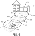
- Fig. 6 schematically shows a sixth exemplary embodiment of the presence detecting system according to the invention wherein the area 5 is an outdoor area with three zones 9A;9B;9C and wherein the object it a vehicle, in particular a car 3.
- the presence detection system is used to detect a presence of the car that is approaching a garage 21.
- the sensors 11A;11B;11C sense the car in the zones 9A;9B;9C respectively.
- the system can be for example configured that the outdoor light 17 is switched on if the presence of the car in the zones 11C, 11B and 11A is sequentially detected.
Landscapes
- Geophysics And Detection Of Objects (AREA)
- Optical Radar Systems And Details Thereof (AREA)
Applications Claiming Priority (2)
| Application Number | Priority Date | Filing Date | Title |
|---|---|---|---|
| EP10153063 | 2010-02-09 | ||
| PCT/IB2011/050383 WO2011098931A1 (en) | 2010-02-09 | 2011-01-28 | Presence detection system and lighting system comprising such system |
Publications (3)
| Publication Number | Publication Date |
|---|---|
| EP2534929A1 EP2534929A1 (en) | 2012-12-19 |
| EP2534929B1 EP2534929B1 (en) | 2019-03-13 |
| EP2534929B2 true EP2534929B2 (en) | 2022-02-16 |
Family
ID=43903848
Family Applications (1)
| Application Number | Title | Priority Date | Filing Date |
|---|---|---|---|
| EP11706345.3A Active EP2534929B2 (en) | 2010-02-09 | 2011-01-28 | Presence detection system and lighting system comprising such system |
Country Status (7)
| Country | Link |
|---|---|
| US (1) | US8866619B2 (enExample) |
| EP (1) | EP2534929B2 (enExample) |
| JP (1) | JP5735008B2 (enExample) |
| CN (1) | CN102742362B (enExample) |
| ES (1) | ES2726950T5 (enExample) |
| TW (1) | TW201143524A (enExample) |
| WO (1) | WO2011098931A1 (enExample) |
Families Citing this family (42)
| Publication number | Priority date | Publication date | Assignee | Title |
|---|---|---|---|---|
| JPH0829787B2 (ja) | 1988-02-26 | 1996-03-27 | ペーアー,ハロルド・ティー | 容器のためのヒンジ止めされた閉塞体 |
| CN103037562B (zh) * | 2011-09-30 | 2015-05-06 | 北京同步科技有限公司 | 智能灯光系统及其控制方法 |
| CN103858523B (zh) * | 2011-10-17 | 2016-08-17 | 皇家飞利浦有限公司 | 调试照明系统 |
| CN104137162B (zh) | 2012-02-29 | 2016-11-23 | 皇家飞利浦有限公司 | 用于位置检测的被动红外传感器系统 |
| US8872432B2 (en) * | 2012-03-15 | 2014-10-28 | General Electric Company | Solution for dynamic lighting control |
| EP2837270B1 (en) * | 2012-04-10 | 2020-06-17 | Signify Holding B.V. | Fault detection, localization and performance monitoring of photosensors for lighting controls |
| JP2014007101A (ja) * | 2012-06-26 | 2014-01-16 | Panasonic Corp | 照明システム |
| US9240118B2 (en) * | 2013-03-14 | 2016-01-19 | Bi Incorporated | Systems and methods for beacon tethering in a monitoring system |
| CN103249224A (zh) * | 2013-04-24 | 2013-08-14 | 无锡商业职业技术学院 | 一种基于Zigbee网络的智能灯光跟随系统 |
| WO2014173724A1 (en) * | 2013-04-26 | 2014-10-30 | Koninklijke Philips N.V. | Sensing within a region |
| US9655207B2 (en) | 2013-08-27 | 2017-05-16 | Philips Lighting Holding B.V. | Sensor network with adaptive detection settings based on the status information from neighboring luminaires and/or connected devices |
| US9671121B2 (en) * | 2014-02-19 | 2017-06-06 | Enlighted, Inc. | Motion tracking |
| US9716861B1 (en) | 2014-03-07 | 2017-07-25 | Steelcase Inc. | Method and system for facilitating collaboration sessions |
| US10664772B1 (en) | 2014-03-07 | 2020-05-26 | Steelcase Inc. | Method and system for facilitating collaboration sessions |
| US9412255B1 (en) * | 2014-05-21 | 2016-08-09 | West Corporation | Remote monitoring of activity triggered sensors and a customized updating application |
| US9955318B1 (en) | 2014-06-05 | 2018-04-24 | Steelcase Inc. | Space guidance and management system and method |
| US9766079B1 (en) | 2014-10-03 | 2017-09-19 | Steelcase Inc. | Method and system for locating resources and communicating within an enterprise |
| US9380682B2 (en) | 2014-06-05 | 2016-06-28 | Steelcase Inc. | Environment optimization for space based on presence and activities |
| US11744376B2 (en) | 2014-06-06 | 2023-09-05 | Steelcase Inc. | Microclimate control systems and methods |
| US10433646B1 (en) | 2014-06-06 | 2019-10-08 | Steelcaase Inc. | Microclimate control systems and methods |
| US9852388B1 (en) | 2014-10-03 | 2017-12-26 | Steelcase, Inc. | Method and system for locating resources and communicating within an enterprise |
| CN104703369B (zh) * | 2015-04-01 | 2018-06-05 | 山东共达电声股份有限公司 | 一种控制灯具的方法及装置 |
| US10733371B1 (en) | 2015-06-02 | 2020-08-04 | Steelcase Inc. | Template based content preparation system for use with a plurality of space types |
| EP3366086A1 (en) * | 2015-10-22 | 2018-08-29 | Philips Lighting Holding B.V. | Trajectory tracking using low cost occupancy sensor |
| CN105927946A (zh) * | 2016-05-03 | 2016-09-07 | 肖梦春 | 一种人体存在侦测系统及侦测人体存在状况的方法 |
| US9921726B1 (en) | 2016-06-03 | 2018-03-20 | Steelcase Inc. | Smart workstation method and system |
| EP3300459B1 (en) | 2016-09-21 | 2019-08-28 | Helvar Oy Ab | Method and arrangement for controlling lighting based on user tracking |
| US11232699B2 (en) | 2016-12-01 | 2022-01-25 | Gojo Industries, Inc. | Monitoring arrangements |
| US10264213B1 (en) | 2016-12-15 | 2019-04-16 | Steelcase Inc. | Content amplification system and method |
| US10585185B2 (en) * | 2017-02-03 | 2020-03-10 | Rohde & Schwarz Gmbh & Co. Kg | Security scanning system with walk-through-gate |
| JP6999299B2 (ja) * | 2017-06-28 | 2022-01-18 | アズビル株式会社 | 照明制御方法および装置 |
| US11520028B2 (en) * | 2018-01-10 | 2022-12-06 | Richwave Technology Corp. | Occupancy detection using multiple antenna motion sensing |
| US11037418B2 (en) * | 2018-05-05 | 2021-06-15 | Current Lighting Solutions, Llc | Distributed occupancy detection system and method |
| TWI669025B (zh) * | 2018-05-28 | 2019-08-11 | 台灣松下電器股份有限公司 | Electrical control method and system |
| JP7331086B2 (ja) | 2018-08-27 | 2023-08-22 | シグニファイ ホールディング ビー ヴィ | Rfベースの存在/位置検出のためのネットワークノードの適合性の判断 |
| US11709245B2 (en) * | 2019-04-29 | 2023-07-25 | Adnoviv Inc. | System and methods for radar-based detection of people in a room |
| JP7503752B2 (ja) * | 2020-03-05 | 2024-06-21 | パナソニックIpマネジメント株式会社 | 情報処理システム、及び、情報処理方法 |
| US12118178B1 (en) | 2020-04-08 | 2024-10-15 | Steelcase Inc. | Wayfinding services method and apparatus |
| US11305964B2 (en) | 2020-07-15 | 2022-04-19 | Leandre Adifon | Systems and methods for operation of elevators and other devices |
| US20220073316A1 (en) | 2020-07-15 | 2022-03-10 | Leandre Adifon | Systems and methods for operation of elevators and other devices |
| US11984739B1 (en) | 2020-07-31 | 2024-05-14 | Steelcase Inc. | Remote power systems, apparatus and methods |
| JP7643401B2 (ja) * | 2022-05-26 | 2025-03-11 | トヨタ自動車株式会社 | 洗浄通知装置、洗浄通知方法、及び洗浄通知プログラム |
Citations (7)
| Publication number | Priority date | Publication date | Assignee | Title |
|---|---|---|---|---|
| US5781108A (en) † | 1995-11-14 | 1998-07-14 | Future Tech Systems, Inc. | Automated detection and monitoring (ADAM) |
| US20040036603A1 (en) † | 2002-08-20 | 2004-02-26 | Bingham Victoria J. | Lighting security system |
| DE102005037571A1 (de) † | 2004-08-13 | 2006-02-23 | Osram Sylvania Inc., Danvers | Verfahren und System zur Beleuchtungsregelung |
| US20070057761A1 (en) † | 2005-04-22 | 2007-03-15 | Geophysical Survey Systems, Inc. | Motion detector |
| US20070279215A1 (en) † | 2006-06-06 | 2007-12-06 | Optex Co., Ltd. | Sensitivity adjustable intrusion detecting system |
| DE60034555T2 (de) † | 1999-02-01 | 2007-12-27 | Beonic Corporation Pty Ltd. | System zur objekterkennung und -verfolgung |
| US20090160660A1 (en) † | 2005-12-09 | 2009-06-25 | Seniortek Oy | Method and System for Guarding a Person in a Building |
Family Cites Families (17)
| Publication number | Priority date | Publication date | Assignee | Title |
|---|---|---|---|---|
| US5142199A (en) * | 1990-11-29 | 1992-08-25 | Novitas, Inc. | Energy efficient infrared light switch and method of making same |
| US5656995A (en) | 1994-04-29 | 1997-08-12 | Hampton Electronics | Object presence detection method and system having quick object departure detection to turn off system |
| JPH07312293A (ja) * | 1994-05-13 | 1995-11-28 | Matsushita Electric Works Ltd | 照明制御システム |
| JP3373725B2 (ja) * | 1996-04-15 | 2003-02-04 | 松下電工株式会社 | 照明装置 |
| JP2000058273A (ja) * | 1998-08-12 | 2000-02-25 | Matsushita Electric Works Ltd | 照明制御システム |
| US6909921B1 (en) | 2000-10-19 | 2005-06-21 | Destiny Networks, Inc. | Occupancy sensor and method for home automation system |
| US6912429B1 (en) | 2000-10-19 | 2005-06-28 | Destiny Networks, Inc. | Home automation system and method |
| US7009497B2 (en) * | 2003-03-21 | 2006-03-07 | Hds Acquisition Company | Method of distinguishing the presence of a single versus multiple persons |
| US7233243B2 (en) | 2004-01-09 | 2007-06-19 | Ctrl Systems, Inc. | Method of defense-in-depth ultrasound intrusion detection |
| RU2325047C1 (ru) * | 2004-02-02 | 2008-05-20 | Ботем Электроник Ко., Лтд. | Энергосберегающий выключатель |
| US20050258954A1 (en) * | 2004-03-11 | 2005-11-24 | Ruskin Thomas R | Apparatus and method for providing motion actuated light |
| US7764167B2 (en) * | 2006-01-18 | 2010-07-27 | British Telecommunications Plc | Monitoring movement of an entity in an environment |
| CA2692187A1 (en) * | 2007-06-29 | 2009-01-08 | Carmanah Technologies Corp. | Intelligent area lighting system |
| KR20090019152A (ko) * | 2007-08-20 | 2009-02-25 | 한국전자통신연구원 | 센서를 이용한 일상생활 행위 인식 방법 및 시스템 |
| JP2009266605A (ja) * | 2008-04-24 | 2009-11-12 | Panasonic Electric Works Co Ltd | 自動調光システム |
| CN201234376Y (zh) * | 2008-07-29 | 2009-05-06 | 济南格林节能开发有限公司 | 一种检测室内人数的照明及用电设备节能控制装置 |
| CN101541123B (zh) * | 2009-05-06 | 2012-05-23 | 钱跃良 | Led路灯的智能控制装置及智能控制方法 |
-
2011
- 2011-01-28 EP EP11706345.3A patent/EP2534929B2/en active Active
- 2011-01-28 CN CN201180008844.5A patent/CN102742362B/zh active Active
- 2011-01-28 ES ES11706345T patent/ES2726950T5/es active Active
- 2011-01-28 US US13/576,960 patent/US8866619B2/en active Active
- 2011-01-28 JP JP2012551714A patent/JP5735008B2/ja active Active
- 2011-01-28 WO PCT/IB2011/050383 patent/WO2011098931A1/en not_active Ceased
- 2011-02-08 TW TW100104164A patent/TW201143524A/zh unknown
Patent Citations (7)
| Publication number | Priority date | Publication date | Assignee | Title |
|---|---|---|---|---|
| US5781108A (en) † | 1995-11-14 | 1998-07-14 | Future Tech Systems, Inc. | Automated detection and monitoring (ADAM) |
| DE60034555T2 (de) † | 1999-02-01 | 2007-12-27 | Beonic Corporation Pty Ltd. | System zur objekterkennung und -verfolgung |
| US20040036603A1 (en) † | 2002-08-20 | 2004-02-26 | Bingham Victoria J. | Lighting security system |
| DE102005037571A1 (de) † | 2004-08-13 | 2006-02-23 | Osram Sylvania Inc., Danvers | Verfahren und System zur Beleuchtungsregelung |
| US20070057761A1 (en) † | 2005-04-22 | 2007-03-15 | Geophysical Survey Systems, Inc. | Motion detector |
| US20090160660A1 (en) † | 2005-12-09 | 2009-06-25 | Seniortek Oy | Method and System for Guarding a Person in a Building |
| US20070279215A1 (en) † | 2006-06-06 | 2007-12-06 | Optex Co., Ltd. | Sensitivity adjustable intrusion detecting system |
Also Published As
| Publication number | Publication date |
|---|---|
| CN102742362A (zh) | 2012-10-17 |
| ES2726950T3 (es) | 2019-10-10 |
| EP2534929B1 (en) | 2019-03-13 |
| JP2013519199A (ja) | 2013-05-23 |
| US20120299733A1 (en) | 2012-11-29 |
| CN102742362B (zh) | 2015-06-03 |
| TW201143524A (en) | 2011-12-01 |
| WO2011098931A1 (en) | 2011-08-18 |
| US8866619B2 (en) | 2014-10-21 |
| JP5735008B2 (ja) | 2015-06-17 |
| EP2534929A1 (en) | 2012-12-19 |
| ES2726950T5 (es) | 2022-04-25 |
Similar Documents
| Publication | Publication Date | Title |
|---|---|---|
| EP2534929B2 (en) | Presence detection system and lighting system comprising such system | |
| US20080273754A1 (en) | Apparatus and method for defining an area of interest for image sensing | |
| US9594151B1 (en) | System and method for locating objects | |
| US20090146817A1 (en) | Monitoring device, monitoring method, and monitoring program | |
| WO2005020169A3 (en) | Logical pet immune intrusion detection apparatus and method | |
| WO2014060903A1 (en) | Occupancy detection method and system | |
| US5656995A (en) | Object presence detection method and system having quick object departure detection to turn off system | |
| WO2016142223A1 (en) | Presence request via light adjustment | |
| US20170163909A1 (en) | Method and system for detecting occupancy in a space | |
| US10038751B2 (en) | Sensor system | |
| JP2010206713A (ja) | 機器制御システム | |
| US12567258B2 (en) | Sensor fusion scheme for occupant detection | |
| US20240318856A1 (en) | Sensor fusion for low power occupancy sensing | |
| KR20200097921A (ko) | 스마트 조명제어 시스템 | |
| WO2013153481A1 (en) | Identification sensor for gate identification of a person | |
| EP3889933A1 (en) | A system for monitoring a space by a portable sensor device and a method thereof | |
| JP2010117889A (ja) | 防犯システム | |
| CN106815545A (zh) | 行为分析系统和行为分析方法 | |
| CN219456953U (zh) | 一种酒店智能探测报警装置 | |
| CN205485395U (zh) | 建筑及建材的自动感应系统 | |
| WO2019210519A1 (zh) | 一种空间分区探测系统及方法 | |
| JPH03219394A (ja) | 人数および火災の検知装置 | |
| CN105549443B (zh) | 建筑及建材的自动感应系统 | |
| Ogawa et al. | A face recognition system for automated door opening with parallel health status validation using the kinect v2 | |
| JP2020035590A (ja) | 照明制御装置および方法 |
Legal Events
| Date | Code | Title | Description |
|---|---|---|---|
| PUAI | Public reference made under article 153(3) epc to a published international application that has entered the european phase |
Free format text: ORIGINAL CODE: 0009012 |
|
| 17P | Request for examination filed |
Effective date: 20120910 |
|
| AK | Designated contracting states |
Kind code of ref document: A1 Designated state(s): AL AT BE BG CH CY CZ DE DK EE ES FI FR GB GR HR HU IE IS IT LI LT LU LV MC MK MT NL NO PL PT RO RS SE SI SK SM TR |
|
| DAX | Request for extension of the european patent (deleted) | ||
| RAP1 | Party data changed (applicant data changed or rights of an application transferred) |
Owner name: KONINKLIJKE PHILIPS N.V. |
|
| RAP1 | Party data changed (applicant data changed or rights of an application transferred) |
Owner name: PHILIPS LIGHTING HOLDING B.V. |
|
| 17Q | First examination report despatched |
Effective date: 20160928 |
|
| STAA | Information on the status of an ep patent application or granted ep patent |
Free format text: STATUS: EXAMINATION IS IN PROGRESS |
|
| RIN1 | Information on inventor provided before grant (corrected) |
Inventor name: KLEE, MAREIKE Inventor name: PASVEER, WILLEM, FRANKE Inventor name: KNIBBE, ENGEL, JOHANNES Inventor name: SREEDHARAN NAIR, BIJU, KUMAR Inventor name: MILLS, JOHN, BREAN Inventor name: DELNOIJ, ROGER, PETER, ANNA |
|
| GRAP | Despatch of communication of intention to grant a patent |
Free format text: ORIGINAL CODE: EPIDOSNIGR1 |
|
| STAA | Information on the status of an ep patent application or granted ep patent |
Free format text: STATUS: GRANT OF PATENT IS INTENDED |
|
| GRAJ | Information related to disapproval of communication of intention to grant by the applicant or resumption of examination proceedings by the epo deleted |
Free format text: ORIGINAL CODE: EPIDOSDIGR1 |
|
| STAA | Information on the status of an ep patent application or granted ep patent |
Free format text: STATUS: EXAMINATION IS IN PROGRESS |
|
| INTG | Intention to grant announced |
Effective date: 20180718 |
|
| GRAP | Despatch of communication of intention to grant a patent |
Free format text: ORIGINAL CODE: EPIDOSNIGR1 |
|
| STAA | Information on the status of an ep patent application or granted ep patent |
Free format text: STATUS: GRANT OF PATENT IS INTENDED |
|
| INTC | Intention to grant announced (deleted) | ||
| INTG | Intention to grant announced |
Effective date: 20180830 |
|
| RAP1 | Party data changed (applicant data changed or rights of an application transferred) |
Owner name: PHILIPS LIGHTING HOLDING B.V. |
|
| GRAS | Grant fee paid |
Free format text: ORIGINAL CODE: EPIDOSNIGR3 |
|
| GRAA | (expected) grant |
Free format text: ORIGINAL CODE: 0009210 |
|
| STAA | Information on the status of an ep patent application or granted ep patent |
Free format text: STATUS: THE PATENT HAS BEEN GRANTED |
|
| AK | Designated contracting states |
Kind code of ref document: B1 Designated state(s): AL AT BE BG CH CY CZ DE DK EE ES FI FR GB GR HR HU IE IS IT LI LT LU LV MC MK MT NL NO PL PT RO RS SE SI SK SM TR |
|
| RAP1 | Party data changed (applicant data changed or rights of an application transferred) |
Owner name: SIGNIFY HOLDING B.V. |
|
| REG | Reference to a national code |
Ref country code: GB Ref legal event code: FG4D |
|
| REG | Reference to a national code |
Ref country code: CH Ref legal event code: EP Ref country code: AT Ref legal event code: REF Ref document number: 1109486 Country of ref document: AT Kind code of ref document: T Effective date: 20190315 |
|
| REG | Reference to a national code |
Ref country code: IE Ref legal event code: FG4D |
|
| REG | Reference to a national code |
Ref country code: DE Ref legal event code: R096 Ref document number: 602011057078 Country of ref document: DE |
|
| REG | Reference to a national code |
Ref country code: NL Ref legal event code: FP |
|
| REG | Reference to a national code |
Ref country code: SE Ref legal event code: TRGR |
|
| REG | Reference to a national code |
Ref country code: LT Ref legal event code: MG4D |
|
| PG25 | Lapsed in a contracting state [announced via postgrant information from national office to epo] |
Ref country code: FI Free format text: LAPSE BECAUSE OF FAILURE TO SUBMIT A TRANSLATION OF THE DESCRIPTION OR TO PAY THE FEE WITHIN THE PRESCRIBED TIME-LIMIT Effective date: 20190313 Ref country code: NO Free format text: LAPSE BECAUSE OF FAILURE TO SUBMIT A TRANSLATION OF THE DESCRIPTION OR TO PAY THE FEE WITHIN THE PRESCRIBED TIME-LIMIT Effective date: 20190613 Ref country code: LT Free format text: LAPSE BECAUSE OF FAILURE TO SUBMIT A TRANSLATION OF THE DESCRIPTION OR TO PAY THE FEE WITHIN THE PRESCRIBED TIME-LIMIT Effective date: 20190313 |
|
| PG25 | Lapsed in a contracting state [announced via postgrant information from national office to epo] |
Ref country code: HR Free format text: LAPSE BECAUSE OF FAILURE TO SUBMIT A TRANSLATION OF THE DESCRIPTION OR TO PAY THE FEE WITHIN THE PRESCRIBED TIME-LIMIT Effective date: 20190313 Ref country code: RS Free format text: LAPSE BECAUSE OF FAILURE TO SUBMIT A TRANSLATION OF THE DESCRIPTION OR TO PAY THE FEE WITHIN THE PRESCRIBED TIME-LIMIT Effective date: 20190313 Ref country code: BG Free format text: LAPSE BECAUSE OF FAILURE TO SUBMIT A TRANSLATION OF THE DESCRIPTION OR TO PAY THE FEE WITHIN THE PRESCRIBED TIME-LIMIT Effective date: 20190613 Ref country code: GR Free format text: LAPSE BECAUSE OF FAILURE TO SUBMIT A TRANSLATION OF THE DESCRIPTION OR TO PAY THE FEE WITHIN THE PRESCRIBED TIME-LIMIT Effective date: 20190614 Ref country code: LV Free format text: LAPSE BECAUSE OF FAILURE TO SUBMIT A TRANSLATION OF THE DESCRIPTION OR TO PAY THE FEE WITHIN THE PRESCRIBED TIME-LIMIT Effective date: 20190313 |
|
| REG | Reference to a national code |
Ref country code: AT Ref legal event code: MK05 Ref document number: 1109486 Country of ref document: AT Kind code of ref document: T Effective date: 20190313 |
|
| REG | Reference to a national code |
Ref country code: ES Ref legal event code: FG2A Ref document number: 2726950 Country of ref document: ES Kind code of ref document: T3 Effective date: 20191010 |
|
| PG25 | Lapsed in a contracting state [announced via postgrant information from national office to epo] |
Ref country code: EE Free format text: LAPSE BECAUSE OF FAILURE TO SUBMIT A TRANSLATION OF THE DESCRIPTION OR TO PAY THE FEE WITHIN THE PRESCRIBED TIME-LIMIT Effective date: 20190313 Ref country code: SK Free format text: LAPSE BECAUSE OF FAILURE TO SUBMIT A TRANSLATION OF THE DESCRIPTION OR TO PAY THE FEE WITHIN THE PRESCRIBED TIME-LIMIT Effective date: 20190313 Ref country code: AL Free format text: LAPSE BECAUSE OF FAILURE TO SUBMIT A TRANSLATION OF THE DESCRIPTION OR TO PAY THE FEE WITHIN THE PRESCRIBED TIME-LIMIT Effective date: 20190313 Ref country code: PT Free format text: LAPSE BECAUSE OF FAILURE TO SUBMIT A TRANSLATION OF THE DESCRIPTION OR TO PAY THE FEE WITHIN THE PRESCRIBED TIME-LIMIT Effective date: 20190713 Ref country code: RO Free format text: LAPSE BECAUSE OF FAILURE TO SUBMIT A TRANSLATION OF THE DESCRIPTION OR TO PAY THE FEE WITHIN THE PRESCRIBED TIME-LIMIT Effective date: 20190313 Ref country code: CZ Free format text: LAPSE BECAUSE OF FAILURE TO SUBMIT A TRANSLATION OF THE DESCRIPTION OR TO PAY THE FEE WITHIN THE PRESCRIBED TIME-LIMIT Effective date: 20190313 |
|
| PG25 | Lapsed in a contracting state [announced via postgrant information from national office to epo] |
Ref country code: SM Free format text: LAPSE BECAUSE OF FAILURE TO SUBMIT A TRANSLATION OF THE DESCRIPTION OR TO PAY THE FEE WITHIN THE PRESCRIBED TIME-LIMIT Effective date: 20190313 Ref country code: PL Free format text: LAPSE BECAUSE OF FAILURE TO SUBMIT A TRANSLATION OF THE DESCRIPTION OR TO PAY THE FEE WITHIN THE PRESCRIBED TIME-LIMIT Effective date: 20190313 |
|
| REG | Reference to a national code |
Ref country code: DE Ref legal event code: R026 Ref document number: 602011057078 Country of ref document: DE |
|
| PLBI | Opposition filed |
Free format text: ORIGINAL CODE: 0009260 |
|
| PG25 | Lapsed in a contracting state [announced via postgrant information from national office to epo] |
Ref country code: AT Free format text: LAPSE BECAUSE OF FAILURE TO SUBMIT A TRANSLATION OF THE DESCRIPTION OR TO PAY THE FEE WITHIN THE PRESCRIBED TIME-LIMIT Effective date: 20190313 Ref country code: IS Free format text: LAPSE BECAUSE OF FAILURE TO SUBMIT A TRANSLATION OF THE DESCRIPTION OR TO PAY THE FEE WITHIN THE PRESCRIBED TIME-LIMIT Effective date: 20190713 |
|
| PLAX | Notice of opposition and request to file observation + time limit sent |
Free format text: ORIGINAL CODE: EPIDOSNOBS2 |
|
| 26 | Opposition filed |
Opponent name: MOLNIA, DAVID Effective date: 20191212 |
|
| PG25 | Lapsed in a contracting state [announced via postgrant information from national office to epo] |
Ref country code: DK Free format text: LAPSE BECAUSE OF FAILURE TO SUBMIT A TRANSLATION OF THE DESCRIPTION OR TO PAY THE FEE WITHIN THE PRESCRIBED TIME-LIMIT Effective date: 20190313 |
|
| PG25 | Lapsed in a contracting state [announced via postgrant information from national office to epo] |
Ref country code: SI Free format text: LAPSE BECAUSE OF FAILURE TO SUBMIT A TRANSLATION OF THE DESCRIPTION OR TO PAY THE FEE WITHIN THE PRESCRIBED TIME-LIMIT Effective date: 20190313 |
|
| PG25 | Lapsed in a contracting state [announced via postgrant information from national office to epo] |
Ref country code: TR Free format text: LAPSE BECAUSE OF FAILURE TO SUBMIT A TRANSLATION OF THE DESCRIPTION OR TO PAY THE FEE WITHIN THE PRESCRIBED TIME-LIMIT Effective date: 20190313 |
|
| PLBB | Reply of patent proprietor to notice(s) of opposition received |
Free format text: ORIGINAL CODE: EPIDOSNOBS3 |
|
| PG25 | Lapsed in a contracting state [announced via postgrant information from national office to epo] |
Ref country code: MC Free format text: LAPSE BECAUSE OF FAILURE TO SUBMIT A TRANSLATION OF THE DESCRIPTION OR TO PAY THE FEE WITHIN THE PRESCRIBED TIME-LIMIT Effective date: 20190313 |
|
| REG | Reference to a national code |
Ref country code: CH Ref legal event code: PL |
|
| REG | Reference to a national code |
Ref country code: BE Ref legal event code: MM Effective date: 20200131 |
|
| PG25 | Lapsed in a contracting state [announced via postgrant information from national office to epo] |
Ref country code: LU Free format text: LAPSE BECAUSE OF NON-PAYMENT OF DUE FEES Effective date: 20200128 |
|
| PG25 | Lapsed in a contracting state [announced via postgrant information from national office to epo] |
Ref country code: CH Free format text: LAPSE BECAUSE OF NON-PAYMENT OF DUE FEES Effective date: 20200131 Ref country code: LI Free format text: LAPSE BECAUSE OF NON-PAYMENT OF DUE FEES Effective date: 20200131 Ref country code: BE Free format text: LAPSE BECAUSE OF NON-PAYMENT OF DUE FEES Effective date: 20200131 |
|
| PG25 | Lapsed in a contracting state [announced via postgrant information from national office to epo] |
Ref country code: IE Free format text: LAPSE BECAUSE OF NON-PAYMENT OF DUE FEES Effective date: 20200128 |
|
| RIC2 | Information provided on ipc code assigned after grant |
Ipc: H05B 47/155 20200101AFI20210325BHEP Ipc: H05B 47/13 20200101ALI20210325BHEP |
|
| PUAH | Patent maintained in amended form |
Free format text: ORIGINAL CODE: 0009272 |
|
| STAA | Information on the status of an ep patent application or granted ep patent |
Free format text: STATUS: PATENT MAINTAINED AS AMENDED |
|
| 27A | Patent maintained in amended form |
Effective date: 20220216 |
|
| AK | Designated contracting states |
Kind code of ref document: B2 Designated state(s): AL AT BE BG CH CY CZ DE DK EE ES FI FR GB GR HR HU IE IS IT LI LT LU LV MC MK MT NL NO PL PT RO RS SE SI SK SM TR |
|
| REG | Reference to a national code |
Ref country code: DE Ref legal event code: R102 Ref document number: 602011057078 Country of ref document: DE |
|
| REG | Reference to a national code |
Ref country code: NL Ref legal event code: FP |
|
| REG | Reference to a national code |
Ref country code: ES Ref legal event code: DC2A Ref document number: 2726950 Country of ref document: ES Kind code of ref document: T5 Effective date: 20220425 |
|
| PG25 | Lapsed in a contracting state [announced via postgrant information from national office to epo] |
Ref country code: MT Free format text: LAPSE BECAUSE OF FAILURE TO SUBMIT A TRANSLATION OF THE DESCRIPTION OR TO PAY THE FEE WITHIN THE PRESCRIBED TIME-LIMIT Effective date: 20190313 Ref country code: CY Free format text: LAPSE BECAUSE OF FAILURE TO SUBMIT A TRANSLATION OF THE DESCRIPTION OR TO PAY THE FEE WITHIN THE PRESCRIBED TIME-LIMIT Effective date: 20190313 |
|
| REG | Reference to a national code |
Ref country code: SE Ref legal event code: RPEO |
|
| PG25 | Lapsed in a contracting state [announced via postgrant information from national office to epo] |
Ref country code: MK Free format text: LAPSE BECAUSE OF FAILURE TO SUBMIT A TRANSLATION OF THE DESCRIPTION OR TO PAY THE FEE WITHIN THE PRESCRIBED TIME-LIMIT Effective date: 20190313 |
|
| P01 | Opt-out of the competence of the unified patent court (upc) registered |
Effective date: 20230421 |
|
| PGFP | Annual fee paid to national office [announced via postgrant information from national office to epo] |
Ref country code: NL Payment date: 20260122 Year of fee payment: 16 |
|
| PGFP | Annual fee paid to national office [announced via postgrant information from national office to epo] |
Ref country code: SE Payment date: 20260126 Year of fee payment: 16 |
|
| PGFP | Annual fee paid to national office [announced via postgrant information from national office to epo] |
Ref country code: GB Payment date: 20260126 Year of fee payment: 16 |
|
| PGFP | Annual fee paid to national office [announced via postgrant information from national office to epo] |
Ref country code: ES Payment date: 20260210 Year of fee payment: 16 |
|
| PGFP | Annual fee paid to national office [announced via postgrant information from national office to epo] |
Ref country code: DE Payment date: 20260320 Year of fee payment: 16 |
|
| PGFP | Annual fee paid to national office [announced via postgrant information from national office to epo] |
Ref country code: IT Payment date: 20260123 Year of fee payment: 16 |
|
| PGFP | Annual fee paid to national office [announced via postgrant information from national office to epo] |
Ref country code: FR Payment date: 20260126 Year of fee payment: 16 |