EP2533947B1 - Improvements in and relating to implements - Google Patents
Improvements in and relating to implements Download PDFInfo
- Publication number
- EP2533947B1 EP2533947B1 EP11740096.0A EP11740096A EP2533947B1 EP 2533947 B1 EP2533947 B1 EP 2533947B1 EP 11740096 A EP11740096 A EP 11740096A EP 2533947 B1 EP2533947 B1 EP 2533947B1
- Authority
- EP
- European Patent Office
- Prior art keywords
- implement
- plug
- shaft
- slide
- tool
- Prior art date
- Legal status (The legal status is an assumption and is not a legal conclusion. Google has not performed a legal analysis and makes no representation as to the accuracy of the status listed.)
- Active
Links
Images

Classifications
-
- B—PERFORMING OPERATIONS; TRANSPORTING
- B25—HAND TOOLS; PORTABLE POWER-DRIVEN TOOLS; MANIPULATORS
- B25G—HANDLES FOR HAND IMPLEMENTS
- B25G1/00—Handle constructions
- B25G1/04—Handle constructions telescopic; extensible; sectional
-
- A—HUMAN NECESSITIES
- A01—AGRICULTURE; FORESTRY; ANIMAL HUSBANDRY; HUNTING; TRAPPING; FISHING
- A01B—SOIL WORKING IN AGRICULTURE OR FORESTRY; PARTS, DETAILS, OR ACCESSORIES OF AGRICULTURAL MACHINES OR IMPLEMENTS, IN GENERAL
- A01B1/00—Hand tools
- A01B1/22—Attaching the blades or the like to handles; Interchangeable or adjustable blades
-
- B—PERFORMING OPERATIONS; TRANSPORTING
- B25—HAND TOOLS; PORTABLE POWER-DRIVEN TOOLS; MANIPULATORS
- B25D—PERCUSSIVE TOOLS
- B25D1/00—Hand hammers; Hammer heads of special shape or materials
- B25D1/16—Hand hammers; Hammer heads of special shape or materials having the impacting head in the form of a sleeve slidable on a shaft, e.g. hammers for driving a valve or draw-off tube into a barrel
-
- B—PERFORMING OPERATIONS; TRANSPORTING
- B25—HAND TOOLS; PORTABLE POWER-DRIVEN TOOLS; MANIPULATORS
- B25G—HANDLES FOR HAND IMPLEMENTS
- B25G3/00—Attaching handles to the implements
- B25G3/02—Socket, tang, or like fixings
- B25G3/12—Locking and securing devices
-
- B—PERFORMING OPERATIONS; TRANSPORTING
- B25—HAND TOOLS; PORTABLE POWER-DRIVEN TOOLS; MANIPULATORS
- B25D—PERCUSSIVE TOOLS
- B25D2250/00—General details of portable percussive tools; Components used in portable percussive tools
- B25D2250/065—Details regarding assembling of the tool
- B25D2250/075—Assembled by welding
-
- Y—GENERAL TAGGING OF NEW TECHNOLOGICAL DEVELOPMENTS; GENERAL TAGGING OF CROSS-SECTIONAL TECHNOLOGIES SPANNING OVER SEVERAL SECTIONS OF THE IPC; TECHNICAL SUBJECTS COVERED BY FORMER USPC CROSS-REFERENCE ART COLLECTIONS [XRACs] AND DIGESTS
- Y10—TECHNICAL SUBJECTS COVERED BY FORMER USPC
- Y10T—TECHNICAL SUBJECTS COVERED BY FORMER US CLASSIFICATION
- Y10T29/00—Metal working
- Y10T29/49—Method of mechanical manufacture
- Y10T29/49826—Assembling or joining
- Y10T29/49947—Assembling or joining by applying separate fastener
- Y10T29/49966—Assembling or joining by applying separate fastener with supplemental joining
- Y10T29/49968—Metal fusion joining
Definitions
- the present invention relates to improvements in and relating to implements.
- the present invention relates to digging or driven implements, primarily those used for digging through tough materials such as hardened clay, stony or root laden ground.
- Slide hammer assisted digging tools are one such well known implement.
- the slide hammer allows the user to apply extremely high energy impulses to drive a tool portion such as an implement head through tough materials, typically the implement head will be a spade head or similar type blade.
- US-A-2004/0045412 discloses an implement suitable for digging and comprising all the features of the preamble of claim 1.
- US 5,890,254 discloses a hand manipulated implement including an implement head, a handle and a connector rigidly connecting the handle to the implement head. It is an object of the present invention to address the foregoing problems or at least to provide the public with a useful choice.
- the plug may be retained at one end of the shaft in a variety of different ways.
- the plug may have an engaging portion which is shaped and dimensioned to precision fit within a hollow section of the shaft.
- the lateral dimensions of the engaging portion being only marginally smaller than the lateral dimensions of the hollow section of the shaft into which plug fits.
- the plug may have an engaging portion which is shaped and dimensioned to precision fit around a section of the shaft.
- the internal dimensions of the engaging portion being only marginally larger than the external dimensions of the section of the shaft.
- the plug may also be adhered to at least part of the shaft.
- a filling agent may be inserted between the plug and at least part of the shaft.
- the contact area between the plug and shaft should provide a sufficiently precision fit so as to prevent relative movement therebetween.
- the second section may include an aperture or slot therein to facilitate the attachment of a tool portion.
- the implement characterised in that any impact forces applied in a direction inline with the longitudinal axis of the shaft are transferred through the plug directly to the tool head.
- the second portion of the plug provides an increased weld surface area transverse to the longitudinal direction of force, thereby greatly improving the strength of the tool to longitudinally applied stresses.
- longitudinally applied forces may be transferred through a number of physical connections, such as but not limited to:
- the engaging portion also provides a precision fit, or otherwise prevents relative movement between the plug and the shaft.
- the tool portion is attached to the plug by reinforced welds. It will however be obvious to those skilled in the art that the means by which the tool portion is attached to the plug could be achieved in any number of ways without departing from the scope of the present invention.
- the tool portion is attached to the plug by a filling agent such as a high strength resin. In other embodiments the tool portion is attached by crimping of the tool portion within the plug aperture.
- the implement head may be cast to include integral tool and plugs.
- the implement includes a sliding hammer, as is well known in the art, the sliding hammer including a handle portion and a slide portion.
- the slide portion may, in use, be located into or onto a corresponding guide portion on or in the shaft of the implement.
- the guide portion of the implement may be a substantially tubular section into which the slide portion of the slide hammer is located.
- cross sectional profile of the slide portion of the slide hammer will be substantially the same as the guide portion of the implement, and could be any one of square, circular or triangular.
- the cross sectional profile should therefore not be seen as being limiting.
- the handle portion of the slide hammer includes a plurality of apertures therein.
- the slide portion of the slide hammer includes a plurality of apertures therein, each aperture corresponding to a matching aperture in the handle portion of the slide hammer.
- the apertures in the slide hammer handle portion and slide portion aligning coaxially upon correct location of the slide portion within the handle portion.
- the slide hammer handle portion is affixed to the slide hammer slide portion by a plurality of pins located through each of the coaxially aligned apertures in the said slide hammer handle portion and slide portion.
- the pins located through the said coaxially aligned apertures in the said slide hammer handle portion and slide portion are affixed into position.
- the pins in the slide hammer are welded into position. It will however be obvious to those skilled in the art that there any number of ways in which the pins could be affixed in position, by way of example a second option could be to peen or press a solid rivet (pin) into position.
- the slide portion of the slide hammer impacts against a region of the first section of the plug that is located within the receiving portion of the shaft. It will be apparent to a person skilled in the art that this configuration results in forces generated from the impact of the slide portion of the slide hammer with the plug being transferred directly to the implement head and not along the length of the receiving portion.
- an implement for use with a slide hammer which includes:
- a shaft of an implement substantially as described above, wherein the shaft includes an impact hammer at one end thereof.
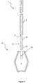
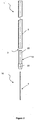
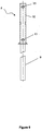
- the digging implement (1) has a shaft (2), which has a receiving portion in the form of an aperture (3) at one end thereof.
- the digging implement (1) also has an implement head (15), the implement head (15) including a plug (13) having; a first section (20) with a cross sectional profile (not shown)(but which is, in the preferred embodiment, substantially circular in cross sectional profile) matching the profile (not shown)(but which is in the preferred embodiment, substantially circular in cross sectional profile) of the receiving portion (3) of the shaft (2); and a second section (21) which has a cross sectional profile (not shown)(but which is in the preferred embodiment, substantially circular in cross sectional profile) which is not capable of fitting into the receiving portion (3) of the shaft (2).
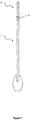
- a digging implement (1) including a shaft (2) and an implement head (15).
- the implement head (15) including a plug (13) which is attached to tool portion (5), which in this embodiment is a blade.
- the blade (5) includes aperture (23) into which the plug (13) is located, the plug second section (21) includes aperture (22), shown in Figure 2 , into which the blade (5) locates when the plug (13) is positioned in the blade (5) aperture (23), this is most clearly shown in Figure 4 .
- the blade is welded (not shown) in place along the adjacent edges (25) of the plug second section (21) and blade (5) surface.
- the plug (13) is fittingly engaged within the receiving portion (3) of the shaft (2), shown in Figures 2 and 3 .
- the implement head (15) is affixed to the shaft (2) by fitting engagement between the first section (20) of the plug (13) and the receiving portion (3) of the shaft (2).
- the plug (13) is welded (not shown) to the shaft (2) along the adjacent edges (26) of the first portion of the plug (13) and the shaft (2), the blade (5) is welded to the shaft (2) along the adjacent edges (24) of the of blade (5) aperture (23) and the sides of the shaft (2).
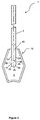
- FIG. 4 there is shown a cross sectional view of the implement (1), including a shaft (2) and implement head (5).
- the implement head (5) including a plug (13) and a tool portion (5).
- the plug (13) having a first section (16) shown inserted into the receiving portion (3) of the shaft (2).
- the second section (21) of the plug (13) abuts the shaft (2) when fully inserted.
- the second section (21) of the plug (13) includes aperture (22) into which the tool portion (5) inserts.
- the shaft (2) also includes a guide region (7) in the form of a hollow interior into which a slide hammer (not shown in Figures 1 , 2 or 3 ) can be located.
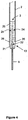
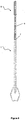
- FIG. 5 there is shown an exploded view of a slide hammer (8), having a slide portion (9), and a handle portion (10).
- the slide portion (9) being inserted into the handle portion (10), such that one or more apertures (11) in the handle portion (10) align coaxially with corresponding apertures (12) in the slide portion (9) when the slide portion (9) is located therein.
- a slide hammer (8) including a slide portion (9) affixed to a handle portion (10) by pins (15) passing through the said coaxially aligned apertures (11, 12) in the handle portion (10) and slide portion (9).
- FIG. 7 there is shown a digging implement (1) including a slide hammer (8) in an impacted position, the slide hammer (8) slide portion (9) abutting the plug of the implement head (13 in Figure 1 , not shown in Figure 6 ).
- a digging implement (1) including a slide hammer (8) in an extended position, the slide hammer (8) slide portion (9) being guided by the guide portion (7).
Landscapes
- Engineering & Computer Science (AREA)
- Mechanical Engineering (AREA)
- Life Sciences & Earth Sciences (AREA)
- Soil Sciences (AREA)
- Environmental Sciences (AREA)
- Percussive Tools And Related Accessories (AREA)
- Portable Nailing Machines And Staplers (AREA)
Priority Applications (1)
| Application Number | Priority Date | Filing Date | Title |
|---|---|---|---|
| PL11740096T PL2533947T3 (pl) | 2010-02-08 | 2011-02-08 | Udoskonalenia w i dotyczące przyrządów |
Applications Claiming Priority (2)
| Application Number | Priority Date | Filing Date | Title |
|---|---|---|---|
| NZ58318110 | 2010-02-08 | ||
| PCT/NZ2011/000017 WO2011096831A1 (en) | 2010-02-08 | 2011-02-08 | Improvements in and relating to implements |
Publications (3)
| Publication Number | Publication Date |
|---|---|
| EP2533947A1 EP2533947A1 (en) | 2012-12-19 |
| EP2533947A4 EP2533947A4 (en) | 2017-06-28 |
| EP2533947B1 true EP2533947B1 (en) | 2019-05-22 |
Family
ID=44355628
Family Applications (1)
| Application Number | Title | Priority Date | Filing Date |
|---|---|---|---|
| EP11740096.0A Active EP2533947B1 (en) | 2010-02-08 | 2011-02-08 | Improvements in and relating to implements |
Country Status (10)
| Country | Link |
|---|---|
| US (1) | US9283668B2 (pl) |
| EP (1) | EP2533947B1 (pl) |
| CN (1) | CN102821916B (pl) |
| AU (1) | AU2011213367B2 (pl) |
| BR (1) | BR112012019492B1 (pl) |
| CA (1) | CA2789008C (pl) |
| ES (1) | ES2738501T3 (pl) |
| PL (1) | PL2533947T3 (pl) |
| WO (1) | WO2011096831A1 (pl) |
| ZA (1) | ZA201206667B (pl) |
Families Citing this family (1)
| Publication number | Priority date | Publication date | Assignee | Title |
|---|---|---|---|---|
| CN103460883B (zh) * | 2013-09-11 | 2016-05-25 | 中国农业大学 | 一种挤压式挖根装置 |
Family Cites Families (28)
| Publication number | Priority date | Publication date | Assignee | Title |
|---|---|---|---|---|
| US1473143A (en) * | 1922-11-20 | 1923-11-06 | James M Dean | Plow scraper and cleaner |
| US1665109A (en) * | 1927-07-26 | 1928-04-03 | Henry A Nelson | Trimmer |
| US1931349A (en) * | 1932-02-16 | 1933-10-17 | Habig John Francis | Grass edger |
| US1931926A (en) * | 1932-03-07 | 1933-10-24 | Johnson David | Floor scraper |
| GB491687A (en) | 1936-09-03 | 1938-09-07 | Max Ploen | A device for exchangeable connection of a handle to an implement body |
| US2485877A (en) * | 1946-01-16 | 1949-10-25 | Jr Vivian E Hamilton | Lawn edging implement |
| US2529342A (en) * | 1948-04-19 | 1950-11-07 | Clarence L Kopplin | Extension handle for shovels and the like |
| US2661252A (en) * | 1950-08-31 | 1953-12-01 | Joseph E Girard | Implement handle securing key |
| GB1454223A (en) * | 1974-11-14 | 1976-11-03 | Kendrick Sinonsen T | Tools for gardening farming roadworking and the like |
| US4470440A (en) * | 1982-09-30 | 1984-09-11 | Thor Harry A | Impact producing tool |
| US4624323A (en) * | 1985-02-07 | 1986-11-25 | Burrola Henry G | Multi-purpose impact hand tool kit |
| US4722634A (en) * | 1985-10-03 | 1988-02-02 | Malish Terrance J | Adapter device for brooms or the like |
| US5040614A (en) * | 1990-11-15 | 1991-08-20 | Charles Nash | Self-operated edging tool |
| US5434063A (en) * | 1991-12-20 | 1995-07-18 | The United States Of America As Represented By The United States Department Of Energy | Sequential cloning of chromosomes |
| US5529129A (en) * | 1994-05-27 | 1996-06-25 | Byrd; Ernie | Hand-held trenching tool |
| US5775674A (en) * | 1996-10-15 | 1998-07-07 | Bigham; Vern | Lift apparatus having a pivoting pole for lifting and moving a manhole cover |
| US5890254A (en) * | 1997-09-16 | 1999-04-06 | O-Cedar Brands, Inc. | Implement with E-clip handle attachment and handle alignment mechanism |
| US5878822A (en) * | 1997-11-19 | 1999-03-09 | Roy; Willard G. | Tool with interchangeable heads |
| US6474198B2 (en) * | 1999-03-30 | 2002-11-05 | Slide Sledge Technology, Inc. | Slide hammer |
| US6125719A (en) * | 1999-03-30 | 2000-10-03 | Slide Sledge Technology, Inc. | Slide hammer |
| JP2001225122A (ja) * | 2000-02-15 | 2001-08-21 | Honda Motor Co Ltd | プレス用ダイの製造方法及びプレス用パンチの製造方法 |
| US6568729B2 (en) * | 2001-10-09 | 2003-05-27 | Karlus D. Bailey | Fiber shovel |
| US20030184104A1 (en) * | 2002-03-14 | 2003-10-02 | Great Neck Saw Manufacturers, Inc. | Foldable shovel |
| US20040045412A1 (en) * | 2002-09-10 | 2004-03-11 | Cotner Terry Lee | Slide hammer confidential and proprietary document |
| US7293361B1 (en) * | 2004-05-07 | 2007-11-13 | Ames True Temper, Inc. | Hand tool for chopping ice |
| US7325625B1 (en) * | 2005-07-21 | 2008-02-05 | Fathom Leaks, Llc | Floor covering removal and impact tool |
| USD547627S1 (en) * | 2005-11-17 | 2007-07-31 | Meads David P | Drywall tool |
| NZ583181A (en) | 2011-02-08 | 2012-08-31 | Timothy James Irvin | Slide hammer comprising a shaft, plug and a tool portion |
-
2011
- 2011-02-08 CA CA2789008A patent/CA2789008C/en active Active
- 2011-02-08 PL PL11740096T patent/PL2533947T3/pl unknown
- 2011-02-08 BR BR112012019492-5A patent/BR112012019492B1/pt active IP Right Grant
- 2011-02-08 US US13/576,935 patent/US9283668B2/en active Active
- 2011-02-08 AU AU2011213367A patent/AU2011213367B2/en active Active
- 2011-02-08 WO PCT/NZ2011/000017 patent/WO2011096831A1/en not_active Ceased
- 2011-02-08 ES ES11740096T patent/ES2738501T3/es active Active
- 2011-02-08 EP EP11740096.0A patent/EP2533947B1/en active Active
- 2011-02-08 CN CN201180008721.1A patent/CN102821916B/zh active Active
-
2012
- 2012-09-06 ZA ZA2012/06667A patent/ZA201206667B/en unknown
Non-Patent Citations (1)
| Title |
|---|
| None * |
Also Published As
| Publication number | Publication date |
|---|---|
| CN102821916B (zh) | 2016-06-01 |
| AU2011213367A1 (en) | 2012-09-27 |
| US9283668B2 (en) | 2016-03-15 |
| BR112012019492A2 (pt) | 2016-04-19 |
| ES2738501T3 (es) | 2020-01-23 |
| CN102821916A (zh) | 2012-12-12 |
| US20120299320A1 (en) | 2012-11-29 |
| WO2011096831A1 (en) | 2011-08-11 |
| BR112012019492B1 (pt) | 2021-03-16 |
| EP2533947A1 (en) | 2012-12-19 |
| AU2011213367B2 (en) | 2014-03-27 |
| EP2533947A4 (en) | 2017-06-28 |
| CA2789008A1 (en) | 2011-08-11 |
| PL2533947T3 (pl) | 2019-11-29 |
| ZA201206667B (en) | 2013-12-23 |
| CA2789008C (en) | 2018-07-10 |
Similar Documents
| Publication | Publication Date | Title |
|---|---|---|
| US10213932B2 (en) | Handle protector for a hand tool | |
| JP4842458B2 (ja) | 掘削用工具 | |
| US6606925B1 (en) | Handle for a hand tool, especially a screwdriver grip | |
| CN106368260B (zh) | 用于机具的磨损部件保持系统 | |
| US20140245645A1 (en) | Mechanical system comprising a device for connection between a wearing part and the support thereof, heavy-construction machine bucket, and method for implementing said system | |
| WO2006033818A3 (en) | Pin assembly and method for ground engaging tooth system | |
| CN102802399A (zh) | 土地耕作工具 | |
| WO2016179262A1 (en) | Hand tool handle assembly and method of manufacture | |
| CN106368261B (zh) | 用于机具的磨损部件保持系统 | |
| WO2015134106A1 (en) | Aluminum striking tools | |
| US9243419B2 (en) | Support wire implanting anchor | |
| EP2533947B1 (en) | Improvements in and relating to implements | |
| US20130091745A1 (en) | End bit for a soil-working tool | |
| US20080179101A1 (en) | Auger | |
| US20120317768A1 (en) | Lateral pin extraction tool and lateral pin extraction tool set for working machine bucket | |
| CN108519733B (zh) | 一种钟表机芯秒轮分轮时轮结构 | |
| US6883221B1 (en) | Pin removal and placement tool | |
| WO2003087492A1 (en) | Reinforcing bar coupler | |
| KR200415829Y1 (ko) | 망치 | |
| MX2011013642A (es) | Herramienta de percusion para un martillo de demolicion o semejantes. | |
| EP2931479B1 (de) | Werkzeughalter | |
| EP2642063A1 (en) | A drill bit for percussive drilling | |
| EP4656022A1 (en) | Shaft of hand tool for agricultural, horticultural or earth work | |
| EP3022364A1 (en) | Ground working tool with replaceable teeth | |
| KR100856009B1 (ko) | 중장비용 버킷의 투스 포인트 교체기구 |
Legal Events
| Date | Code | Title | Description |
|---|---|---|---|
| PUAI | Public reference made under article 153(3) epc to a published international application that has entered the european phase |
Free format text: ORIGINAL CODE: 0009012 |
|
| 17P | Request for examination filed |
Effective date: 20120905 |
|
| AK | Designated contracting states |
Kind code of ref document: A1 Designated state(s): AL AT BE BG CH CY CZ DE DK EE ES FI FR GB GR HR HU IE IS IT LI LT LU LV MC MK MT NL NO PL PT RO RS SE SI SK SM TR |
|
| DAX | Request for extension of the european patent (deleted) | ||
| RA4 | Supplementary search report drawn up and despatched (corrected) |
Effective date: 20170526 |
|
| RIC1 | Information provided on ipc code assigned before grant |
Ipc: B25G 3/04 20060101AFI20170519BHEP Ipc: A01B 1/22 20060101ALI20170519BHEP Ipc: A01D 1/08 20060101ALI20170519BHEP Ipc: B25D 1/16 20060101ALI20170519BHEP Ipc: B25G 3/00 20060101ALI20170519BHEP |
|
| GRAP | Despatch of communication of intention to grant a patent |
Free format text: ORIGINAL CODE: EPIDOSNIGR1 |
|
| STAA | Information on the status of an ep patent application or granted ep patent |
Free format text: STATUS: GRANT OF PATENT IS INTENDED |
|
| INTG | Intention to grant announced |
Effective date: 20181129 |
|
| GRAS | Grant fee paid |
Free format text: ORIGINAL CODE: EPIDOSNIGR3 |
|
| GRAA | (expected) grant |
Free format text: ORIGINAL CODE: 0009210 |
|
| STAA | Information on the status of an ep patent application or granted ep patent |
Free format text: STATUS: THE PATENT HAS BEEN GRANTED |
|
| AK | Designated contracting states |
Kind code of ref document: B1 Designated state(s): AL AT BE BG CH CY CZ DE DK EE ES FI FR GB GR HR HU IE IS IT LI LT LU LV MC MK MT NL NO PL PT RO RS SE SI SK SM TR |
|
| REG | Reference to a national code |
Ref country code: GB Ref legal event code: FG4D |
|
| REG | Reference to a national code |
Ref country code: CH Ref legal event code: EP |
|
| REG | Reference to a national code |
Ref country code: IE Ref legal event code: FG4D |
|
| REG | Reference to a national code |
Ref country code: DE Ref legal event code: R096 Ref document number: 602011059182 Country of ref document: DE |
|
| REG | Reference to a national code |
Ref country code: AT Ref legal event code: REF Ref document number: 1135536 Country of ref document: AT Kind code of ref document: T Effective date: 20190615 |
|
| REG | Reference to a national code |
Ref country code: NL Ref legal event code: MP Effective date: 20190522 |
|
| REG | Reference to a national code |
Ref country code: LT Ref legal event code: MG4D |
|
| PG25 | Lapsed in a contracting state [announced via postgrant information from national office to epo] |
Ref country code: AL Free format text: LAPSE BECAUSE OF FAILURE TO SUBMIT A TRANSLATION OF THE DESCRIPTION OR TO PAY THE FEE WITHIN THE PRESCRIBED TIME-LIMIT Effective date: 20190522 Ref country code: HR Free format text: LAPSE BECAUSE OF FAILURE TO SUBMIT A TRANSLATION OF THE DESCRIPTION OR TO PAY THE FEE WITHIN THE PRESCRIBED TIME-LIMIT Effective date: 20190522 Ref country code: NO Free format text: LAPSE BECAUSE OF FAILURE TO SUBMIT A TRANSLATION OF THE DESCRIPTION OR TO PAY THE FEE WITHIN THE PRESCRIBED TIME-LIMIT Effective date: 20190822 Ref country code: SE Free format text: LAPSE BECAUSE OF FAILURE TO SUBMIT A TRANSLATION OF THE DESCRIPTION OR TO PAY THE FEE WITHIN THE PRESCRIBED TIME-LIMIT Effective date: 20190522 Ref country code: PT Free format text: LAPSE BECAUSE OF FAILURE TO SUBMIT A TRANSLATION OF THE DESCRIPTION OR TO PAY THE FEE WITHIN THE PRESCRIBED TIME-LIMIT Effective date: 20190922 Ref country code: FI Free format text: LAPSE BECAUSE OF FAILURE TO SUBMIT A TRANSLATION OF THE DESCRIPTION OR TO PAY THE FEE WITHIN THE PRESCRIBED TIME-LIMIT Effective date: 20190522 Ref country code: LT Free format text: LAPSE BECAUSE OF FAILURE TO SUBMIT A TRANSLATION OF THE DESCRIPTION OR TO PAY THE FEE WITHIN THE PRESCRIBED TIME-LIMIT Effective date: 20190522 Ref country code: NL Free format text: LAPSE BECAUSE OF FAILURE TO SUBMIT A TRANSLATION OF THE DESCRIPTION OR TO PAY THE FEE WITHIN THE PRESCRIBED TIME-LIMIT Effective date: 20190522 |
|
| PG25 | Lapsed in a contracting state [announced via postgrant information from national office to epo] |
Ref country code: RS Free format text: LAPSE BECAUSE OF FAILURE TO SUBMIT A TRANSLATION OF THE DESCRIPTION OR TO PAY THE FEE WITHIN THE PRESCRIBED TIME-LIMIT Effective date: 20190522 Ref country code: LV Free format text: LAPSE BECAUSE OF FAILURE TO SUBMIT A TRANSLATION OF THE DESCRIPTION OR TO PAY THE FEE WITHIN THE PRESCRIBED TIME-LIMIT Effective date: 20190522 Ref country code: BG Free format text: LAPSE BECAUSE OF FAILURE TO SUBMIT A TRANSLATION OF THE DESCRIPTION OR TO PAY THE FEE WITHIN THE PRESCRIBED TIME-LIMIT Effective date: 20190822 Ref country code: GR Free format text: LAPSE BECAUSE OF FAILURE TO SUBMIT A TRANSLATION OF THE DESCRIPTION OR TO PAY THE FEE WITHIN THE PRESCRIBED TIME-LIMIT Effective date: 20190823 |
|
| REG | Reference to a national code |
Ref country code: AT Ref legal event code: MK05 Ref document number: 1135536 Country of ref document: AT Kind code of ref document: T Effective date: 20190522 |
|
| REG | Reference to a national code |
Ref country code: ES Ref legal event code: FG2A Ref document number: 2738501 Country of ref document: ES Kind code of ref document: T3 Effective date: 20200123 |
|
| PG25 | Lapsed in a contracting state [announced via postgrant information from national office to epo] |
Ref country code: AT Free format text: LAPSE BECAUSE OF FAILURE TO SUBMIT A TRANSLATION OF THE DESCRIPTION OR TO PAY THE FEE WITHIN THE PRESCRIBED TIME-LIMIT Effective date: 20190522 Ref country code: EE Free format text: LAPSE BECAUSE OF FAILURE TO SUBMIT A TRANSLATION OF THE DESCRIPTION OR TO PAY THE FEE WITHIN THE PRESCRIBED TIME-LIMIT Effective date: 20190522 Ref country code: DK Free format text: LAPSE BECAUSE OF FAILURE TO SUBMIT A TRANSLATION OF THE DESCRIPTION OR TO PAY THE FEE WITHIN THE PRESCRIBED TIME-LIMIT Effective date: 20190522 Ref country code: SK Free format text: LAPSE BECAUSE OF FAILURE TO SUBMIT A TRANSLATION OF THE DESCRIPTION OR TO PAY THE FEE WITHIN THE PRESCRIBED TIME-LIMIT Effective date: 20190522 Ref country code: RO Free format text: LAPSE BECAUSE OF FAILURE TO SUBMIT A TRANSLATION OF THE DESCRIPTION OR TO PAY THE FEE WITHIN THE PRESCRIBED TIME-LIMIT Effective date: 20190522 Ref country code: CZ Free format text: LAPSE BECAUSE OF FAILURE TO SUBMIT A TRANSLATION OF THE DESCRIPTION OR TO PAY THE FEE WITHIN THE PRESCRIBED TIME-LIMIT Effective date: 20190522 |
|
| REG | Reference to a national code |
Ref country code: DE Ref legal event code: R097 Ref document number: 602011059182 Country of ref document: DE |
|
| PG25 | Lapsed in a contracting state [announced via postgrant information from national office to epo] |
Ref country code: SM Free format text: LAPSE BECAUSE OF FAILURE TO SUBMIT A TRANSLATION OF THE DESCRIPTION OR TO PAY THE FEE WITHIN THE PRESCRIBED TIME-LIMIT Effective date: 20190522 |
|
| PLBE | No opposition filed within time limit |
Free format text: ORIGINAL CODE: 0009261 |
|
| STAA | Information on the status of an ep patent application or granted ep patent |
Free format text: STATUS: NO OPPOSITION FILED WITHIN TIME LIMIT |
|
| PG25 | Lapsed in a contracting state [announced via postgrant information from national office to epo] |
Ref country code: TR Free format text: LAPSE BECAUSE OF FAILURE TO SUBMIT A TRANSLATION OF THE DESCRIPTION OR TO PAY THE FEE WITHIN THE PRESCRIBED TIME-LIMIT Effective date: 20190522 |
|
| 26N | No opposition filed |
Effective date: 20200225 |
|
| PG25 | Lapsed in a contracting state [announced via postgrant information from national office to epo] |
Ref country code: SI Free format text: LAPSE BECAUSE OF FAILURE TO SUBMIT A TRANSLATION OF THE DESCRIPTION OR TO PAY THE FEE WITHIN THE PRESCRIBED TIME-LIMIT Effective date: 20190522 |
|
| REG | Reference to a national code |
Ref country code: CH Ref legal event code: PL |
|
| REG | Reference to a national code |
Ref country code: BE Ref legal event code: MM Effective date: 20200229 |
|
| PG25 | Lapsed in a contracting state [announced via postgrant information from national office to epo] |
Ref country code: LU Free format text: LAPSE BECAUSE OF NON-PAYMENT OF DUE FEES Effective date: 20200208 Ref country code: MC Free format text: LAPSE BECAUSE OF FAILURE TO SUBMIT A TRANSLATION OF THE DESCRIPTION OR TO PAY THE FEE WITHIN THE PRESCRIBED TIME-LIMIT Effective date: 20190522 |
|
| PG25 | Lapsed in a contracting state [announced via postgrant information from national office to epo] |
Ref country code: LI Free format text: LAPSE BECAUSE OF NON-PAYMENT OF DUE FEES Effective date: 20200229 Ref country code: CH Free format text: LAPSE BECAUSE OF NON-PAYMENT OF DUE FEES Effective date: 20200229 |
|
| PG25 | Lapsed in a contracting state [announced via postgrant information from national office to epo] |
Ref country code: BE Free format text: LAPSE BECAUSE OF NON-PAYMENT OF DUE FEES Effective date: 20200229 |
|
| PG25 | Lapsed in a contracting state [announced via postgrant information from national office to epo] |
Ref country code: MT Free format text: LAPSE BECAUSE OF FAILURE TO SUBMIT A TRANSLATION OF THE DESCRIPTION OR TO PAY THE FEE WITHIN THE PRESCRIBED TIME-LIMIT Effective date: 20190522 Ref country code: CY Free format text: LAPSE BECAUSE OF FAILURE TO SUBMIT A TRANSLATION OF THE DESCRIPTION OR TO PAY THE FEE WITHIN THE PRESCRIBED TIME-LIMIT Effective date: 20190522 |
|
| PG25 | Lapsed in a contracting state [announced via postgrant information from national office to epo] |
Ref country code: MK Free format text: LAPSE BECAUSE OF FAILURE TO SUBMIT A TRANSLATION OF THE DESCRIPTION OR TO PAY THE FEE WITHIN THE PRESCRIBED TIME-LIMIT Effective date: 20190522 Ref country code: IS Free format text: LAPSE BECAUSE OF FAILURE TO SUBMIT A TRANSLATION OF THE DESCRIPTION OR TO PAY THE FEE WITHIN THE PRESCRIBED TIME-LIMIT Effective date: 20190922 |
|
| PGFP | Annual fee paid to national office [announced via postgrant information from national office to epo] |
Ref country code: PL Payment date: 20250408 Year of fee payment: 15 Ref country code: DE Payment date: 20250408 Year of fee payment: 15 |
|
| PGFP | Annual fee paid to national office [announced via postgrant information from national office to epo] |
Ref country code: GB Payment date: 20250408 Year of fee payment: 15 Ref country code: ES Payment date: 20250408 Year of fee payment: 15 |
|
| PGFP | Annual fee paid to national office [announced via postgrant information from national office to epo] |
Ref country code: IT Payment date: 20250409 Year of fee payment: 15 |
|
| PGFP | Annual fee paid to national office [announced via postgrant information from national office to epo] |
Ref country code: FR Payment date: 20250408 Year of fee payment: 15 |
|
| PGFP | Annual fee paid to national office [announced via postgrant information from national office to epo] |
Ref country code: IE Payment date: 20250408 Year of fee payment: 15 |