EP2533346A1 - Dispositif de suppression de liquides à partir d'un dispositif de stockage d'énergie - Google Patents
Dispositif de suppression de liquides à partir d'un dispositif de stockage d'énergie Download PDFInfo
- Publication number
- EP2533346A1 EP2533346A1 EP11004698A EP11004698A EP2533346A1 EP 2533346 A1 EP2533346 A1 EP 2533346A1 EP 11004698 A EP11004698 A EP 11004698A EP 11004698 A EP11004698 A EP 11004698A EP 2533346 A1 EP2533346 A1 EP 2533346A1
- Authority
- EP
- European Patent Office
- Prior art keywords
- liquid
- discharge device
- liquid discharge
- energy storage
- storage device
- Prior art date
- Legal status (The legal status is an assumption and is not a legal conclusion. Google has not performed a legal analysis and makes no representation as to the accuracy of the status listed.)
- Withdrawn
Links
Images


Classifications
-
- H—ELECTRICITY
- H01—ELECTRIC ELEMENTS
- H01M—PROCESSES OR MEANS, e.g. BATTERIES, FOR THE DIRECT CONVERSION OF CHEMICAL ENERGY INTO ELECTRICAL ENERGY
- H01M10/00—Secondary cells; Manufacture thereof
- H01M10/42—Methods or arrangements for servicing or maintenance of secondary cells or secondary half-cells
- H01M10/4207—Methods or arrangements for servicing or maintenance of secondary cells or secondary half-cells for several batteries or cells simultaneously or sequentially
-
- B—PERFORMING OPERATIONS; TRANSPORTING
- B60—VEHICLES IN GENERAL
- B60L—PROPULSION OF ELECTRICALLY-PROPELLED VEHICLES; SUPPLYING ELECTRIC POWER FOR AUXILIARY EQUIPMENT OF ELECTRICALLY-PROPELLED VEHICLES; ELECTRODYNAMIC BRAKE SYSTEMS FOR VEHICLES IN GENERAL; MAGNETIC SUSPENSION OR LEVITATION FOR VEHICLES; MONITORING OPERATING VARIABLES OF ELECTRICALLY-PROPELLED VEHICLES; ELECTRIC SAFETY DEVICES FOR ELECTRICALLY-PROPELLED VEHICLES
- B60L1/00—Supplying electric power to auxiliary equipment of vehicles
- B60L1/003—Supplying electric power to auxiliary equipment of vehicles to auxiliary motors, e.g. for pumps, compressors
-
- B—PERFORMING OPERATIONS; TRANSPORTING
- B60—VEHICLES IN GENERAL
- B60L—PROPULSION OF ELECTRICALLY-PROPELLED VEHICLES; SUPPLYING ELECTRIC POWER FOR AUXILIARY EQUIPMENT OF ELECTRICALLY-PROPELLED VEHICLES; ELECTRODYNAMIC BRAKE SYSTEMS FOR VEHICLES IN GENERAL; MAGNETIC SUSPENSION OR LEVITATION FOR VEHICLES; MONITORING OPERATING VARIABLES OF ELECTRICALLY-PROPELLED VEHICLES; ELECTRIC SAFETY DEVICES FOR ELECTRICALLY-PROPELLED VEHICLES
- B60L1/00—Supplying electric power to auxiliary equipment of vehicles
- B60L1/02—Supplying electric power to auxiliary equipment of vehicles to electric heating circuits
- B60L1/04—Supplying electric power to auxiliary equipment of vehicles to electric heating circuits fed by the power supply line
-
- B—PERFORMING OPERATIONS; TRANSPORTING
- B60—VEHICLES IN GENERAL
- B60L—PROPULSION OF ELECTRICALLY-PROPELLED VEHICLES; SUPPLYING ELECTRIC POWER FOR AUXILIARY EQUIPMENT OF ELECTRICALLY-PROPELLED VEHICLES; ELECTRODYNAMIC BRAKE SYSTEMS FOR VEHICLES IN GENERAL; MAGNETIC SUSPENSION OR LEVITATION FOR VEHICLES; MONITORING OPERATING VARIABLES OF ELECTRICALLY-PROPELLED VEHICLES; ELECTRIC SAFETY DEVICES FOR ELECTRICALLY-PROPELLED VEHICLES
- B60L50/00—Electric propulsion with power supplied within the vehicle
- B60L50/40—Electric propulsion with power supplied within the vehicle using propulsion power supplied by capacitors
-
- B—PERFORMING OPERATIONS; TRANSPORTING
- B60—VEHICLES IN GENERAL
- B60L—PROPULSION OF ELECTRICALLY-PROPELLED VEHICLES; SUPPLYING ELECTRIC POWER FOR AUXILIARY EQUIPMENT OF ELECTRICALLY-PROPELLED VEHICLES; ELECTRODYNAMIC BRAKE SYSTEMS FOR VEHICLES IN GENERAL; MAGNETIC SUSPENSION OR LEVITATION FOR VEHICLES; MONITORING OPERATING VARIABLES OF ELECTRICALLY-PROPELLED VEHICLES; ELECTRIC SAFETY DEVICES FOR ELECTRICALLY-PROPELLED VEHICLES
- B60L50/00—Electric propulsion with power supplied within the vehicle
- B60L50/50—Electric propulsion with power supplied within the vehicle using propulsion power supplied by batteries or fuel cells
- B60L50/60—Electric propulsion with power supplied within the vehicle using propulsion power supplied by batteries or fuel cells using power supplied by batteries
- B60L50/64—Constructional details of batteries specially adapted for electric vehicles
-
- B—PERFORMING OPERATIONS; TRANSPORTING
- B60—VEHICLES IN GENERAL
- B60L—PROPULSION OF ELECTRICALLY-PROPELLED VEHICLES; SUPPLYING ELECTRIC POWER FOR AUXILIARY EQUIPMENT OF ELECTRICALLY-PROPELLED VEHICLES; ELECTRODYNAMIC BRAKE SYSTEMS FOR VEHICLES IN GENERAL; MAGNETIC SUSPENSION OR LEVITATION FOR VEHICLES; MONITORING OPERATING VARIABLES OF ELECTRICALLY-PROPELLED VEHICLES; ELECTRIC SAFETY DEVICES FOR ELECTRICALLY-PROPELLED VEHICLES
- B60L58/00—Methods or circuit arrangements for monitoring or controlling batteries or fuel cells, specially adapted for electric vehicles
- B60L58/10—Methods or circuit arrangements for monitoring or controlling batteries or fuel cells, specially adapted for electric vehicles for monitoring or controlling batteries
- B60L58/24—Methods or circuit arrangements for monitoring or controlling batteries or fuel cells, specially adapted for electric vehicles for monitoring or controlling batteries for controlling the temperature of batteries
- B60L58/26—Methods or circuit arrangements for monitoring or controlling batteries or fuel cells, specially adapted for electric vehicles for monitoring or controlling batteries for controlling the temperature of batteries by cooling
-
- G—PHYSICS
- G01—MEASURING; TESTING
- G01F—MEASURING VOLUME, VOLUME FLOW, MASS FLOW OR LIQUID LEVEL; METERING BY VOLUME
- G01F23/00—Indicating or measuring liquid level or level of fluent solid material, e.g. indicating in terms of volume or indicating by means of an alarm
- G01F23/22—Indicating or measuring liquid level or level of fluent solid material, e.g. indicating in terms of volume or indicating by means of an alarm by measuring physical variables, other than linear dimensions, pressure or weight, dependent on the level to be measured, e.g. by difference of heat transfer of steam or water
- G01F23/26—Indicating or measuring liquid level or level of fluent solid material, e.g. indicating in terms of volume or indicating by means of an alarm by measuring physical variables, other than linear dimensions, pressure or weight, dependent on the level to be measured, e.g. by difference of heat transfer of steam or water by measuring variations of capacity or inductance of capacitors or inductors arising from the presence of liquid or fluent solid material in the electric or electromagnetic fields
- G01F23/263—Indicating or measuring liquid level or level of fluent solid material, e.g. indicating in terms of volume or indicating by means of an alarm by measuring physical variables, other than linear dimensions, pressure or weight, dependent on the level to be measured, e.g. by difference of heat transfer of steam or water by measuring variations of capacity or inductance of capacitors or inductors arising from the presence of liquid or fluent solid material in the electric or electromagnetic fields by measuring variations in capacitance of capacitors
- G01F23/265—Indicating or measuring liquid level or level of fluent solid material, e.g. indicating in terms of volume or indicating by means of an alarm by measuring physical variables, other than linear dimensions, pressure or weight, dependent on the level to be measured, e.g. by difference of heat transfer of steam or water by measuring variations of capacity or inductance of capacitors or inductors arising from the presence of liquid or fluent solid material in the electric or electromagnetic fields by measuring variations in capacitance of capacitors for discrete levels
-
- H—ELECTRICITY
- H01—ELECTRIC ELEMENTS
- H01M—PROCESSES OR MEANS, e.g. BATTERIES, FOR THE DIRECT CONVERSION OF CHEMICAL ENERGY INTO ELECTRICAL ENERGY
- H01M50/00—Constructional details or processes of manufacture of the non-active parts of electrochemical cells other than fuel cells, e.g. hybrid cells
- H01M50/30—Arrangements for facilitating escape of gases
- H01M50/317—Re-sealable arrangements
- H01M50/325—Re-sealable arrangements comprising deformable valve members, e.g. elastic or flexible valve members
-
- H—ELECTRICITY
- H01—ELECTRIC ELEMENTS
- H01M—PROCESSES OR MEANS, e.g. BATTERIES, FOR THE DIRECT CONVERSION OF CHEMICAL ENERGY INTO ELECTRICAL ENERGY
- H01M50/00—Constructional details or processes of manufacture of the non-active parts of electrochemical cells other than fuel cells, e.g. hybrid cells
- H01M50/30—Arrangements for facilitating escape of gases
- H01M50/342—Non-re-sealable arrangements
-
- H—ELECTRICITY
- H01—ELECTRIC ELEMENTS
- H01M—PROCESSES OR MEANS, e.g. BATTERIES, FOR THE DIRECT CONVERSION OF CHEMICAL ENERGY INTO ELECTRICAL ENERGY
- H01M50/00—Constructional details or processes of manufacture of the non-active parts of electrochemical cells other than fuel cells, e.g. hybrid cells
- H01M50/60—Arrangements or processes for filling or topping-up with liquids; Arrangements or processes for draining liquids from casings
- H01M50/691—Arrangements or processes for draining liquids from casings; Cleaning battery or cell casings
-
- H—ELECTRICITY
- H01—ELECTRIC ELEMENTS
- H01M—PROCESSES OR MEANS, e.g. BATTERIES, FOR THE DIRECT CONVERSION OF CHEMICAL ENERGY INTO ELECTRICAL ENERGY
- H01M2200/00—Safety devices for primary or secondary batteries
- H01M2200/20—Pressure-sensitive devices
-
- H—ELECTRICITY
- H01—ELECTRIC ELEMENTS
- H01M—PROCESSES OR MEANS, e.g. BATTERIES, FOR THE DIRECT CONVERSION OF CHEMICAL ENERGY INTO ELECTRICAL ENERGY
- H01M50/00—Constructional details or processes of manufacture of the non-active parts of electrochemical cells other than fuel cells, e.g. hybrid cells
- H01M50/20—Mountings; Secondary casings or frames; Racks, modules or packs; Suspension devices; Shock absorbers; Transport or carrying devices; Holders
- H01M50/249—Mountings; Secondary casings or frames; Racks, modules or packs; Suspension devices; Shock absorbers; Transport or carrying devices; Holders specially adapted for aircraft or vehicles, e.g. cars or trains
-
- H—ELECTRICITY
- H01—ELECTRIC ELEMENTS
- H01M—PROCESSES OR MEANS, e.g. BATTERIES, FOR THE DIRECT CONVERSION OF CHEMICAL ENERGY INTO ELECTRICAL ENERGY
- H01M6/00—Primary cells; Manufacture thereof
- H01M6/50—Methods or arrangements for servicing or maintenance, e.g. for maintaining operating temperature
- H01M6/5044—Cells or batteries structurally combined with cell condition indicating means
-
- Y—GENERAL TAGGING OF NEW TECHNOLOGICAL DEVELOPMENTS; GENERAL TAGGING OF CROSS-SECTIONAL TECHNOLOGIES SPANNING OVER SEVERAL SECTIONS OF THE IPC; TECHNICAL SUBJECTS COVERED BY FORMER USPC CROSS-REFERENCE ART COLLECTIONS [XRACs] AND DIGESTS
- Y02—TECHNOLOGIES OR APPLICATIONS FOR MITIGATION OR ADAPTATION AGAINST CLIMATE CHANGE
- Y02E—REDUCTION OF GREENHOUSE GAS [GHG] EMISSIONS, RELATED TO ENERGY GENERATION, TRANSMISSION OR DISTRIBUTION
- Y02E60/00—Enabling technologies; Technologies with a potential or indirect contribution to GHG emissions mitigation
- Y02E60/10—Energy storage using batteries
-
- Y—GENERAL TAGGING OF NEW TECHNOLOGICAL DEVELOPMENTS; GENERAL TAGGING OF CROSS-SECTIONAL TECHNOLOGIES SPANNING OVER SEVERAL SECTIONS OF THE IPC; TECHNICAL SUBJECTS COVERED BY FORMER USPC CROSS-REFERENCE ART COLLECTIONS [XRACs] AND DIGESTS
- Y02—TECHNOLOGIES OR APPLICATIONS FOR MITIGATION OR ADAPTATION AGAINST CLIMATE CHANGE
- Y02T—CLIMATE CHANGE MITIGATION TECHNOLOGIES RELATED TO TRANSPORTATION
- Y02T10/00—Road transport of goods or passengers
- Y02T10/60—Other road transportation technologies with climate change mitigation effect
- Y02T10/70—Energy storage systems for electromobility, e.g. batteries
Definitions
- the present invention relates to apparatus for removing liquid from an energy storage device, and to energy storage devices comprising such apparatus and uses of the apparatus.
- Electric and electrochemical energy storage such as batteries and capacitors, contain sealed cells that are placed in a housing.
- the outer casing serves to protect the cells from mechanical damage, from contamination and from the ingress of liquids from the environment.
- the cells do not completely fill the housing so that an unused dead volume remains. This arises, for example, by using round cells in a square housing or in the integration of electronic components.
- batteries having a volume of 5 to over 200 l have a dead volume of about 5 to 50%.
- the accumulation of liquids In energy poller devices can lead to impairments of performance and in extreme cases to failure. For example, creepage currents or short circuits can occur when condensate comes in contact with live parts.
- the liquid can also cause the corrosion of metallic components, especially when sour gases, such as HCl or sulfur oxides, from the ambient air through the condensate into the battery interior.
- desiccants and superabsorbents swell during use, which in turn can lead to short circuits or creepage currents and requires time-consuming removal at regular intervals. Swollen superabsorbents may form conductive bridges within the energy storage device or exert mechanical forces on cables or other components in the energy storage device. With desiccants there is also the danger that corrosive or electrically conductive components, such as calcium chloride or phosphoric acid, are released.
- the prior art also attempts to selectively divert condensation with the help of additional electrical components. For example, a sensor in a housing signal that a solenoid valve is to open targeted or that a pump is activated, which dissipates the condensation.
- a sensor in a housing signal that a solenoid valve is to open targeted or that a pump is activated, which dissipates the condensation.
- the problem is that such solutions are technically relatively complex and prone to failure. In addition, they consume energy, which is not desirable in many applications, such as batteries or fuel cells of low-range electric vehicles.
- Another disadvantage is that the condensate is not removed continuously in such solutions, but only after exceeding a defined threshold. As a result, some water content in the housing is tolerated, but this can already lead to the problems described above, such as corrosion.
- the invention has for its object to provide devices and uses which overcome the disadvantages described above. It is a simple and efficient device should be provided to remove condensate and other liquids from the inside of energy storage devices and similar devices for storing energy.
- the device itself should work in its basic function purely mechanically without the use of electrical energy. It should be applicable and usable in a simple manner and require as little maintenance as possible.
- the distance condensate and other liquids should preferably be continuous and not only at defined time or control points.
- the device should be usable under various conditions and, for example, be able to remove both small and large quantities of liquid.
- the invention relates to a liquid discharge device, in particular for removing liquid from an energy storage device, wherein the liquid discharge device is connectable to the energy storage device, wherein the liquid discharge device has at least one inlet opening, can pass through the liquid from the energy storage device in the liquid discharge device, wherein the liquid discharge device is a liquid-absorbing Contains device that can deliver liquid to the environment.
- the liquid discharge device preferably serves to remove liquid from an energy storage device.
- the energy storage device is used in particular for the storage of electrical or electrochemical energy.
- Energy storage devices according to the invention include devices for generating and converting electrical or electrochemical energy, such as fuel cells. Suitable energy storage devices are, in particular, those which contain cells for storing, converting and / or generating electrical and / or electrochemical energy in a housing.
- the energy storage device is selected from batteries, capacitors, supercapacitors, accumulators and fuel cells.
- the liquid discharge device serves to remove liquid from the housing of the energy storage device.
- the liquid to be removed is, in particular, condensation water (condensate), but may also be liquid or leakage fluid which has penetrated from the outside from a cooling circuit or an energy storage cell, or a mixture of such liquids.
- the liquid is preferably water or an aqueous solution. However, it may, for example in the case of electrolytes or coolants, also be or at least contain an organic solvent.
- the liquid may contain dissolved components, such as salts or gases.
- the liquid initially accumulates in the interior of the energy storage device.
- the liquid discharge device according to the invention is connected to the energy storage device so that the liquid passes mechanically through the inlet opening into the liquid discharge device. This can be easily ensured by utilizing gravity when the liquid discharge device is mounted on the underside of the energy storage device, preferably at the lowest point of the energy storage device.
- the liquid discharge device may also be mounted laterally or at any other position of the housing of the energy storage device. When used in vehicles, positions can also be selected in which the collecting liquid is transported by typical driving movements.
- the liquid discharge device can be positioned behind or in front of the energy storage device. The liquid is then supplied, for example, by acceleration or deceleration of the liquid discharge device.
- connection of the energy storage device to the liquid discharge device has an inlet opening through which the liquid passes from the energy storage device into the liquid discharge device.
- the liquid is taken up on contact with a liquid-absorbing device thereof.
- the liquid-absorbing device indicates the liquid the environment ("outwards").
- the liquid is dispensed by evaporation. Then the liquid is not released in liquid form, but as a vapor to the environment.
- the liquid discharge device has an outer housing with outer walls.
- a tubular or cylindrical housing is suitable.
- the housing can be directly positively connected to the energy storage device or indirectly, for example via a hose or pipe connection.
- By means of at least one outlet opening it is ensured that liquid can be transferred through the liquid-absorbing device into the environment, that is to say out of the device.
- the liquid-absorbing device is a nonwoven fabric, a woven fabric, a net, a fiber bundle, such as a string, a hollow fiber bundle or a rope, a paper, a liquid-permeable membrane and / or a particle bed.
- the membrane is preferably holy or porous, in particular microporous.
- the liquid-absorbing device serves at the same time for receiving the liquid from the energy storage device and for delivering the liquid to the environment, in particular by evaporation.
- the liquid-absorbing device is a layer. Due to the layered structure, due to the large surface area on both sides, an efficient uptake and discharge of the liquid to the environment can be achieved.
- the liquid-absorbing device and / or layer is preferably hydrophilic, so that an efficient water absorption and discharge is achieved. It is preferable that the rate of water absorption and discharge is high. In contrast, a high water absorption capacity is less significant, since the device is essentially not intended to serve as a liquid storage, but to forward or evaporate the liquid. In this way, an accumulation of large amounts of fluid with the associated problems, such as swelling and weight gain, can be avoided.
- the water-draining layer has a thickness of 0.05 to 10 mm, preferably between 0.1 to 5 mm or between 0.2 to 2 mm.
- the liquid-absorbing layer is preferably arranged parallel to an outer wall of the liquid discharge device.
- the outer wall includes at least one outlet opening for discharging the liquid to the environment.
- the liquid-absorbing layer is a nonwoven fabric. It has been found that nonwovens can, in particular, bring about efficient liquid absorption and release.
- the nonwoven fabric consists of inorganic fibers. It is advantageous that inorganic fibers are largely inert to rotting or decomposition, especially at elevated temperatures and in the presence of moisture. Inorganic fibers may e.g. consist of graphite, metals or mineral components.
- the fleece consists of fibers or filaments of organic polymers.
- fiber thicknesses of less than 15 microns, since the resulting large surface of the nonwoven fabric leads to an efficient fluid absorption.
- the organic polymers may consist of conventional materials, for example polyamide, polyester (PES) or else mixtures, for example of polyamide and polyester.
- hydrophilicized polyolefins for example those with a UV-induced grafting with unsaturated organic substances, such as acrylic acid or maleic anhydride.
- nonwovens with a permanent coating of hydrophilic organic or inorganic particles such as SiO 2 , Al 2 O 3 or TiO 2 .
- the liquid-absorbing device can also consist of bundles of hollow fibers or fiber strands, such as cords or ropes.
- the liquid-absorbing device may also be a bed of hydrophilic particles.
- inorganic particles for example SiO 2 , Al 2 O 3 , TiO 2 or carbon particles, or organic particles, such as superabsorbent (SAP) particles.
- SAP superabsorbent
- particles of biological origin such as wood litter, can be used, in which case their low rot-resistance is taken into account.
- the bed can be arranged between two porous membranes or nonwovens or other separating layers.
- liquid-absorbing devices it is also possible to use any desired combinations of said liquid-absorbing devices.
- laminates of various layers such as nonwovens and particle beds, can be used, or materials can be mixed within a layer.
- the liquid discharge device additionally comprises a porous protective layer disposed between the liquid-absorbing device and the environment, wherein the porous protective layer is permeable to water vapor and liquid-impermeable.
- the porous protective layer is thus arranged so that through it water vapor, which is discharged from the liquid-absorbing device, enters the environment.
- the porous protective layer is a fleece, a net, a woven fabric or a membrane.
- the protective layer is preferably hydrophobicized and / or oleophobed.
- This porous protective layer protects the liquid-absorbing device and thus the inside of the liquid discharge device from the penetration of liquid from the environment.
- the porous protective layer should in particular prevent the ingress of water, for example spray water during operation of vehicles, or oils.
- the protective layer serves as protection against particles, dust and possibly mechanical damage.
- the protective layer may also be formed so as to prevent the penetration of corrosive gases, such as sulfur oxides or nitrogen oxides.
- breathable Materials which are vapor permeable and liquid impermeable are generally known. They are e.g. in clothing applications referred to as "breathable". Such materials are generally based on membranes ("Gore-Tex") or of fiber materials, such as nonwovens, the surfaces of which are rendered hydrophobic, for example by coating with fluorohydrocarbons, silicones or polyurethanes. In a preferred embodiment, the coating is at the same time hydrophobic and oleophobic. In a further preferred embodiment, breathable, hydrophobic membranes, for example based on PTFE (polytetrafluoroethylene) or polyolefins, are used. Depending on the placement of the liquid discharge device, different requirements can be placed on the protective layer.
- PTFE polytetrafluoroethylene
- the device only comes into contact with spray water, then relatively open-pored materials can be used.
- the element also has a wetting capability of e.g. should have more than 500 mm of water, the maximum pores of the nonwoven fabrics or membranes should be at values of below 30 microns (preferably below 20 microns).
- the nonwovens or membranes can be additionally provided with heating elements in a further embodiment.
- a liquid-absorbing layer can be bonded flat to an outer porous protective layer so that a laminate is obtained.
- spacers between the hydrophilic inner layer and the hydrophobic outer layer can reduce the risk that water from the outside penetrates into the liquid discharge device, since no films can form, which push the water through the hydrophilic nonwoven.
- Preferred spacers are, for example, nets, woven fabrics or nonwovens, nonwovens in particular those with larger pores or thicker fibers being suitable.
- the liquid discharge device has an outer protective cover.
- the outer protective cover serves to protect the liquid discharge device against mechanical damage, for example against stone chipping on the underbody of a motor vehicle. It should not affect the removal of liquid from the liquid discharge device and must therefore have holes or larger pores.
- the outer protective cover may for example have the shape of a tube. Incidentally, it may have any shape which is adapted to the housing of the liquid discharge device.
- the protective cover may for example consist of perforated metal or plastic, such as polyamide, TPE or suitable elastomers. It can also be used with a steel wool filled perforated plate. This can be used for depth filtration and to prevent the direct impact of water from the environment or of particles and damage caused by falling rocks.
- Such an outer protective layer also prevents contamination of the liquid discharge device and the functional hydrophilic or hydrophobic water-draining layers.
- the liquid discharge device effects an effective liquid transport from the energy storage device through the liquid-absorbing layer of the liquid discharge device into the outer environment of the liquid discharge device.
- the liquid discharge device has a check valve which interrupts the liquid transport from the energy storage device into the environment when liquid from the environment threatens to penetrate into the liquid discharge device.
- any known check valve can be used, which in the presence of liquid is a passage for liquid closes.
- the check valve has a sealing element which prevents the penetration of externally applied liquid into the energy storage device and thus seals the device so effectively.
- the check valve on a float In a preferred embodiment, the check valve on a float.
- the sealing element itself is designed as a float.
- a float has a lower density than the liquid, especially as water, and is movable in the direction of the passage. The float is raised in a sufficient amount of liquid because of the lower density. Since the float or the sealing element in the overlying passage fit or close with this form-fitting, this is pressed by the increased liquid level in the opening and closes this effectively.
- the liquid discharge device can then no longer absorb any liquid, such as condensed water, until the liquid has been transported again via the liquid-absorbing layer out of the liquid discharge device.
- the float should have a total density of well below 1 kg / l.
- it can consist of specifically lighter solid materials, eg polyolefinic plastics or wood. It may be made of hollow, for example as a hollow sphere, or also include foam or honeycomb structures. Also conceivable is an inner cavity which contains a gas which is specifically lighter than air (eg helium) or a vacuum.
- a gas which is specifically lighter than air (eg helium) or a vacuum.
- the sealing element and / or the float are cylindrical, spherical, conical or annular and / or mounted on a porous or defined holes containing membrane.
- a cylindrical or spherical sealing element can efficiently close a circular opening.
- An annular sealing element may for example be formed as a sealing ring and close an opening with any geometry.
- the attachment of the sealing element on a liquid-permeable, in particular porous or containing holes membrane allows the uniform lifting of the sealing element in the presence of liquid.
- the membrane can act as a float at low density and good mobility or form a float together with a sealing element.
- the sealing function can be ensured by elastomers or thermoplastic elastomers, which are attached to the moving part, or by elastomers or thermoplastic elastomers, which are attached to the rigid part.
- elastomers or else thermoplastic elastomers it is also conceivable to attach elastomers or else thermoplastic elastomers to both parts.
- the sealing element may also be designed as a switch or consist of a swelling elastomer.
- the sealing of the liquid discharge device by the check valve and in particular by the float is reversible, so that after removal of the liquid again the release of the passage.
- the porous membrane to which the sealing member is attached may be laminated with other layers of the liquid discharge device.
- the liquid discharge device comprises a laminate of a porous membrane, a liquid-absorbing device and optionally a porous protective layer. The connection of the layers in the liquid discharge device to a laminate ensures a simple and space-saving construction and a simple replacement during maintenance or damage.
- the liquid discharge device has a safety valve which opens when the maximum permissible overpressure is exceeded.
- a safety valve can be ensured at unacceptable pressure that the energy storage device and the liquid discharge device are not damaged. In this way, a malfunction of the energy storage device can be compensated.
- the safety valve may for example be a simple overpressure element that jumps from a holder at elevated pressure or breaks at a predetermined breaking point.
- An inventive overpressure cover can also be fixed by a permanent magnet. The time of detachment can be adjusted by the size of the magnet and its degree of filling.
- the metallic mating surface is integrated into the seal, so that the valve can also be used in non-magnetic energy storage devices.
- the pressure relief valve may also consist of an elastomer, which is held by outer nipples and dissolves at a defined pressure from the holder.
- the liquid discharge device has at least one sensor.
- a sensor may indicate the accumulation of liquid in the liquid discharge device or the uptake of liquid by the liquid-absorbing layer. In this way, unwanted ingress of liquid into the liquid discharge device or unwanted accumulation of liquid in the liquid discharge device may be indicated.
- a temperature sensor for example, unwanted freezing of the liquid discharge device can be measured.
- the signals can be evaluated by the sensors and, if necessary, measures can be taken which remediate the detected abuses.
- the temperature sensor can induce the switching on of a heating element.
- the liquid sensor may also induce the turning on of a heating element or a fan.
- the liquid sensors can be designed, for example, as capacitive sensors, in which the adsorbing device is arranged between two capacitor plates. Upon adsorption of liquid through the nonwoven fabric layer, the capacitance of the sensor changes, which is detected by the detection device.
- a wireless transmission of the signals via RFID or radio.
- a plurality of sensors are provided to ensure a higher accuracy of the signals and / or to detect liquid levels. With such sensors it is also possible to differentiate liquids. As condensate, so usually mineral-free water, e.g. causes a different signal excursion than coolant or electrolyte, the sensor can also be used as a selective leakage sensor.
- the housing of the liquid discharge device consists for example of metal, plastic, TPE or elastomers.
- the attachment of the liquid discharge device to the energy storage device housing can be done by known methods, for example by screwing, snapping, bracing, gluing or welding.
- no threshold should arise, which could hinder the liquid discharge from the energy storage device.
- the attachment of the liquid discharge device takes place by means of a clipping, in particular a segment clipping or multipoint clipping. These have channels to allow liquid discharge into the liquid discharge device.
- the operation of the liquid discharge device itself and the removal of the liquid without supplying electrical energy carried out This means that preferably there are no electrical components which cause or assist the discharge of the liquid, such as pumps or heating elements.
- the discharge of the liquid can be effected mechanically, for example by utilizing gravity, by capillary forces, by wind or by the wind of a vehicle.
- means are provided which allow the discharge of the liquid mechanically, i. without direct supply of electrical energy.
- the liquid discharge device is designed and / or mounted so that the movement of the energy storage device with the liquid discharge device by the airstream, the evaporation of the liquid is supported on the outside of the device.
- This embodiment is particularly suitable when the energy storage device is part of a motor vehicle, an aircraft or any other mobile machine.
- the liquid discharge device is positioned or configured so that the air flow along the liquid discharge device causes an efficient removal of the liquid.
- supportive means for removing the liquid may be present, such as channels for air supply and air removal, Laval nozzles and devices which support the formation of back vortexes. With regard to the formation of a wind, the positioning of the liquid discharge device is also made under or next to the housing of the energy storage device.
- the liquid discharge device on the outside, in particular at the outlet opening, a rotary member.
- a rotary element is, for example, a rotor or a wind turbine, which is set in motion by wind, in particular wind, and which promotes the evaporation of the liquid.
- the rotating element is designed as a "blast wheel", which rotates in the airstream and ejects liquid droplets emerging from the liquid discharge device mechanically away from the liquid removal device.
- a blast wheel can have a coated surface which leads to the lowest possible wettability and reduces the risk of contamination (for example via the lotus effect).
- the supply of the liquid to the liquid discharge device can be assisted by additional measures.
- it can be ensured in and on the energy storage device via the cooling that there is a particularly low temperature in the vicinity of the liquid discharge device.
- This ensures that a particularly intensive condensation takes place in the immediate vicinity of the liquid discharge device.
- a bead is provided in the bottom of the energy storage device and / or the bottom has a slope towards the inlet opening of the liquid discharge device.
- the liquid, in particular the condensation inside the energy storage device.
- the inlet opening for the discharge of the liquid is positioned relatively far in front of the housing of the energy storage device, since in braking movements and acceleration movements relatively often a movement of the liquid takes place in the front part of the liquid discharge device.
- the hydration in the Bottom of the energy storage device may be assisted by, for example, a hydrophobic coating that assists in the formation and movement of drops.
- the evaporation of the liquid in the liquid discharge device is assisted by a heating element.
- a heating element may be applied, for example, above or inside the liquid-absorbing layer.
- the heating element is mounted between the housing and the water-draining layer, since thereby the water vapor is forced outward from the liquid discharge device.
- an attachment is downwind from the wind.
- the heating element can be configured, for example, as a film heater, for example based on a porous film based on polyester or polyimide.
- Such film heating elements preferably have a porous and optionally expandable structure, which enables incorporation into the liquid discharge device according to the invention in an exact fit.
- the heating element is turned on only when falling below a defined temperature, for example from 0 ° C, on. In this way frost damage or inactivation of the fluid removal device by ice can be prevented.
- the heating element can be operated, for example, by a photovoltaic cell or another self-sufficient energy unit, such as a wind turbine.
- an appropriately sized energy cache is used.
- the heating element uses waste heat of a motor, an electrical converter or the energy storage device. In this way, no additional electronic component is required.
- a hair dryer can be used, for example in the form of a small blower or fan to accelerate evaporation.
- the invention also provides an energy storage device for storing electrical or electrochemical energy, in particular a A battery or a capacitor comprising a liquid discharge device according to the invention for removing liquids from the energy storage device.
- the invention also provides the use of a liquid removal device according to the invention for removing liquid from an energy storage device for storing electrical or electrochemical energy, in particular a battery or a capacitor.
- a liquid removal device for removing liquid from an energy storage device for storing electrical or electrochemical energy, in particular a battery or a capacitor.
- the invention can also be applied to other applications, in the interior of which condensate or other liquid can form, the maximum working temperatures, however, are so low that this condensate does not effectively evaporate from the interior again.
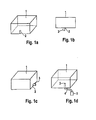
- Fig. 1 shows various ways to attach a liquid discharge device 3 according to the invention to a housing 1 of an energy storage device.
- Fig. 1 a is an attachment shown below the housing.
- Fig. 1b shows a side view.
- Fig. 1c shows a lateral attachment. This takes place in the lower area, so that water can flow into it.
- Fig. 1d shows a spatially separate attachment with a hose or pipe connection 4. It is ensured in each case by an inlet opening 2 in the outer wall of the liquid discharge device that liquid from the energy storage device 1 can penetrate into the liquid discharge device.
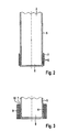
- FIG Fig. 2 An exemplary schematic liquid discharge device 3 is shown in FIG Fig. 2
- the liquid discharge device has lateral outer walls 5, which have outlet openings 6 at least in partial regions. Through this liquid can pass from an energy storage device, which has entered the interior of the liquid discharge device, to the liquid-absorbing device 7, which is arranged laterally on the bottom 8 of the liquid discharge device.
- the liquid-absorbing device 7 is shown schematically as a layer, which consists for example of a nonwoven fabric.
- Fig. 3 shows a remplisstechniksabbowvorrichfung with the features of Fig. 2 , wherein in addition a porous protective layer 9 is applied to the liquid-absorbing device 7, which is spatially separated by spacers 10 from this.
- the liquid-absorbing device 7 is formed as a layer.
- the liquid-absorbing layer conducts the liquid from the inside to the outside, while the porous protective layer 9 allows the escape of water vapor, but prevents the ingress of liquids and also develops a mechanical protective effect.
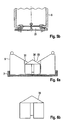
- a liquid discharge device 3 As in Fig. 4 is shown by way of example, a liquid discharge device 3 according to Fig. 2 or Fig. 3 stabilized by an additional outer protection 11, 12 and against the effects of mechanical forces and against contamination and splashing with liquids, etc, are protected.
- Fig. 4a is the external protection schematically as tube 11 and in Fig. 4b as a cylindrical cap (12) containing holes (13) in the outer protection shown.
- FIG. 5 shows a liquid discharge device with outer walls 5, on the underside of a pressure relief valve 20, 21 is mounted.
- Fig. 5a shows an embodiment as a lid 20 and Fig. 5b as a magnetic valve 21.
- FIG. 6 shows a liquid discharge device according to the invention with liquid-absorbing device 7, here formed as a layer, and outer walls 5.
- the check valve comprises according to Fig. 6a a sealing element, which is designed as a float 36, and a passage for liquid 33, such as condensed water.
- Fig. 6b shows a side view of the cylindrical float 36 and Fig. 6c a view with coaxial channels 32, which allow the outflow of the liquid, such as the condensate, in the open state and are closed when closed.
- the float 36 may consist of a thermoplastic, an elastomer or thermoplastic elastomer or have local seals made of these materials. It may preferably also be spherical. Alternatively or in addition to this, the point of contact of the projections 31 with the float 36 may also have a circumferential seal. Under certain circumstances, it may be sufficient to design the projections 31 from a flexible structure, for example a thermoplastic film, which acts on the pressure of the Floating seal. It is also conceivable that the float 36 with a spring or due to its low specific weight in the normal state is already slightly pressed against the counter surface and only by additional weight of action of pending liquid is moved downwards and thus opens. Such an arrangement is advantageous, for example, when there is a high risk of externally pending water. The float is then "closed" in the normal state.
- FIG. 7 shows a liquid discharge device according to the invention with liquid-absorbing device 7, porous layer 9, outer walls 6 and outlet openings 6.
- the liquid is discharged as a vapor through the porous layer 9 in the environment.
- a check valve comprises a membrane 40 which can be latched and fastened with sealing nipples 41 in openings for receiving the sealing nipples 42 of the housing.
- On the membrane 40 a sealing element 30 is attached.
- the membrane 40 has cavities for liquid transfer 43, for example in the form of pores, and is thereby liquid-permeable.
- the membrane Upon penetration of liquid from the outside and accumulation in the cavity 35, the membrane acts as a float with the sealing element and closes by movement up the passage for liquid 33.
- discharging the liquid is the lowering of the membrane 40 and the re-opening of the passage 33, so that again liquid, such as condensation, from the energy storage device can get into the liquid discharge device.
- FIG. 8a shows a check valve with a membrane 40, a sealing element 30 and a passage for liquid 33, such as condensation.
- FIG. 8b shows an alternative arrangement with a sealing ring 34 on a membrane 40th
- FIG. 9a shows an alternative arrangement with membrane 40 without additional sealing element.
- the membrane itself seals the passage 33 from.
- FIG. 9b shows an alternative arrangement with diaphragm 40, sealing member 30 and a spring 45 for bias. Such a spring may cause the membrane 40 to move more easily back to the starting position.
- FIG. 10 shows a check valve with sealing element 30 and an additional float 36 which is connected via a connecting element 37 with the sealing element 30.
- Fig. 11 schematically shows a inertia-controlled valve 46, which is closed when the motor vehicle is stationary and which briefly opens during a movement of the energy storage device by Verzögem the motor vehicle to admit liquid, such as condensation, in the liquid discharge device. It shows Fig. 11 the open state.
- the passage for liquid 33 is opened by the movement of the movable mass elements 47 with attached walls 48, while at rest, the closing takes place via the spring 45.
- Fig. 12a schematically shows a laminate of a membrane 40, which is part of a check valve, with a liquid-absorbing device 7, which is formed as a layer, in particular of nonwoven fabric.
- Fig. 12b shows a corresponding laminate, which additionally has a porous protective layer 9.
- the check valve is designed to close a passage for liquid positioned in front of the liquid-absorbing device.
- the non-return valve can also close a passage for liquid 33, which is connected downstream of the liquid-absorbing device 7 and optionally also the porous protective layer 9. With such a downstream check valve, the evaporation of the liquid from the liquid discharge device can be prevented.
- Such an arrangement has the advantage that the penetration of the liquid from the outside into the liquid-absorbing device 7 can be prevented.
- the liquid discharge device may contain sensors which emit signals about the state of the liquid discharge device.
- Fig. 14 is a liquid discharge device having the features of Fig. 7 shown, which additionally comprises three sensors 50, 51 and 52.
- an overcharge sensor 50 indicates the accumulation of liquid within the check valve.
- a liquid sensor 51 indicates the accumulation of liquid after the check valve.
- the liquid sensor 51 can simultaneously detect liquid that has entered from the environment.
- a temperature sensor 52 may be used to detect icing.
- the signals can be detected and optionally measures are initiated, such as turning on a heater falls below a critical temperature or too high an amount of liquid water.
- Fig. 15 shows a liquid discharge device with a check valve, which has a sealing element 30.
- a rotary member 70 is positioned below the liquid-absorbing device 7, which is formed as a layer, which directs the exiting water vapor from the sosstechniksabbowvorraum.
- Fig. 16 shows a liquid discharge device with check valve of a sealing element and a membrane 40, wherein the sealing element closes a passage for liquid 33.
- the liquid-absorbing device 7, here formed as a layer, and the porous protective layer 9 are arranged vertically. Such an arrangement allows a different kinetics in the discharge of the liquid and an efficient absorption of small amounts of liquid due to the accumulation in the soil area.
- FIG. 17 1 shows an energy storage device 1 with a liquid discharge device 3 attached thereto.
- the energy storage device 1 may be a battery that is positioned in a motor vehicle that generates traveling wind in the direction of the arrow 60.
- the discharge of the liquid can be improved when the liquid discharge device 3 is mounted at a position where the running wind is strong ( Fig. 17a ), or is specifically deflected, for example according to Fig. 17b with a backward vortex 61, or according to Fig. 17c with a nozzle 62, which is for example a Laval nozzle.
- a nozzle 62 which is for example a Laval nozzle.
- the devices and uses of the invention solve the problems underlying the invention.
- the liquid discharge devices allow the simple and efficient removal of condensation and other liquids from the inside of a battery or other energy storage device.
- the removal can be purely mechanical and continuous.
- nonwovens are particularly suitable, which deliver within 15 minutes the highest possible amount of water (as in Example 7).
- Such nonwoven fabrics are particularly efficient in transporting relatively large quantities of water from a liquid discharge device into the environment.
- Table 1 ⁇ / u>: Nonwovens and Results Example fleece Dry weight [g] Wet weight [g] Water tax [g] Water tax [%] 1 ST 170 FC BA 650325/04 0.45 1.09 0.52 0.81 2 ST 170 FC BA 493538/01 0.54 1.28 0.57 0.77 3 ST 171 FC blue BA650519 / 02 0.60 1.50 0.61 0.68 4 ST 3270 BP 650338/01 3.00 4.55 0.48 0.31 5 EVO 60 FC 0.40 0.82 0,3E 0.86 6 EVO 130 0.84 3.08 0.56 0.25 7 FS 2190 0.31 1.07 0.67 0.88 8th cooltexx 1.07 6.00 0.20 0.04 9 FFA2037 1.17 2.94 0.26 0.15
Priority Applications (1)
| Application Number | Priority Date | Filing Date | Title |
|---|---|---|---|
| EP11004698A EP2533346A1 (fr) | 2011-06-09 | 2011-06-09 | Dispositif de suppression de liquides à partir d'un dispositif de stockage d'énergie |
Applications Claiming Priority (1)
| Application Number | Priority Date | Filing Date | Title |
|---|---|---|---|
| EP11004698A EP2533346A1 (fr) | 2011-06-09 | 2011-06-09 | Dispositif de suppression de liquides à partir d'un dispositif de stockage d'énergie |
Publications (1)
| Publication Number | Publication Date |
|---|---|
| EP2533346A1 true EP2533346A1 (fr) | 2012-12-12 |
Family
ID=44504424
Family Applications (1)
| Application Number | Title | Priority Date | Filing Date |
|---|---|---|---|
| EP11004698A Withdrawn EP2533346A1 (fr) | 2011-06-09 | 2011-06-09 | Dispositif de suppression de liquides à partir d'un dispositif de stockage d'énergie |
Country Status (1)
| Country | Link |
|---|---|
| EP (1) | EP2533346A1 (fr) |
Cited By (9)
| Publication number | Priority date | Publication date | Assignee | Title |
|---|---|---|---|---|
| EP2760075A1 (fr) * | 2013-01-25 | 2014-07-30 | MAGNA STEYR Battery Systems GmbH & Co OG | Système de batterie avec containeur |
| CN103972428A (zh) * | 2013-02-06 | 2014-08-06 | 麦格纳斯太尔电池系统两合公司 | 具有吸收设备的电池系统 |
| DE102014016551A1 (de) * | 2014-11-08 | 2016-05-12 | Audi Ag | Batterie für Kraftfahrzeug |
| EP3385584A1 (fr) * | 2017-04-06 | 2018-10-10 | Carl Freudenberg KG | Dispositif de répartition de pression pour un boîtier |
| DE102018209925A1 (de) * | 2018-06-19 | 2019-12-19 | Bayerische Motoren Werke Aktiengesellschaft | Fahrzeug mit einem Hochvoltspeicher |
| DE102019103415A1 (de) * | 2019-02-12 | 2020-08-13 | Bayerische Motoren Werke Aktiengesellschaft | Vorrichtung mit einem Gehäuse, welches einen Auslass für Flüssigkeit aufweist |
| US11047508B2 (en) | 2017-03-30 | 2021-06-29 | Donaldson Company, Inc. | Vent with relief valve |
| CN114024080A (zh) * | 2021-10-14 | 2022-02-08 | 风帆(扬州)有限责任公司 | 一种散热防水的高效启停电池 |
| US11731067B2 (en) | 2018-08-07 | 2023-08-22 | Mann+Hummel Gmbh | Filter element for filtration and dehumidification of a gas |
Citations (5)
| Publication number | Priority date | Publication date | Assignee | Title |
|---|---|---|---|---|
| JP2005339946A (ja) * | 2004-05-26 | 2005-12-08 | Denso Corp | 非水系二次電池及びその製造方法 |
| JP2008060000A (ja) * | 2006-09-01 | 2008-03-13 | Sony Corp | 電池パックおよび電子機器 |
| DE102008034698A1 (de) * | 2008-07-26 | 2009-06-18 | Daimler Ag | Batterie mit einem Batteriegehäuse |
| EP2290729A1 (fr) * | 2009-08-24 | 2011-03-02 | Carl Freudenberg KG | Accumulateur d' énergie électrique avec une système de compensation de volume |
| DE102009050878A1 (de) * | 2009-10-27 | 2011-04-28 | Carl Freudenberg Kg | Batterie mit einem außerhalb des Batteriegehäuses angeordneten Filterelement |
-
2011
- 2011-06-09 EP EP11004698A patent/EP2533346A1/fr not_active Withdrawn
Patent Citations (5)
| Publication number | Priority date | Publication date | Assignee | Title |
|---|---|---|---|---|
| JP2005339946A (ja) * | 2004-05-26 | 2005-12-08 | Denso Corp | 非水系二次電池及びその製造方法 |
| JP2008060000A (ja) * | 2006-09-01 | 2008-03-13 | Sony Corp | 電池パックおよび電子機器 |
| DE102008034698A1 (de) * | 2008-07-26 | 2009-06-18 | Daimler Ag | Batterie mit einem Batteriegehäuse |
| EP2290729A1 (fr) * | 2009-08-24 | 2011-03-02 | Carl Freudenberg KG | Accumulateur d' énergie électrique avec une système de compensation de volume |
| DE102009050878A1 (de) * | 2009-10-27 | 2011-04-28 | Carl Freudenberg Kg | Batterie mit einem außerhalb des Batteriegehäuses angeordneten Filterelement |
Cited By (19)
| Publication number | Priority date | Publication date | Assignee | Title |
|---|---|---|---|---|
| EP2760075A1 (fr) * | 2013-01-25 | 2014-07-30 | MAGNA STEYR Battery Systems GmbH & Co OG | Système de batterie avec containeur |
| CN103972428A (zh) * | 2013-02-06 | 2014-08-06 | 麦格纳斯太尔电池系统两合公司 | 具有吸收设备的电池系统 |
| EP2770554A1 (fr) * | 2013-02-06 | 2014-08-27 | MAGNA STEYR Battery Systems GmbH & Co OG | Système de batterie avec dispositif d'absorption |
| US9356329B2 (en) | 2013-02-06 | 2016-05-31 | Samsung Sdi Co., Ltd. | Battery system with absorption device |
| CN103972428B (zh) * | 2013-02-06 | 2017-03-01 | 三星Sdi株式会社 | 具有吸收设备的电池系统 |
| DE102014016551A1 (de) * | 2014-11-08 | 2016-05-12 | Audi Ag | Batterie für Kraftfahrzeug |
| DE102014016551A8 (de) * | 2014-11-08 | 2016-10-06 | Audi Ag | Batterie für ein Kraftfahrzeug |
| DE102014016551B4 (de) | 2014-11-08 | 2023-10-26 | Audi Ag | Batterie für ein Kraftfahrzeug |
| US11047508B2 (en) | 2017-03-30 | 2021-06-29 | Donaldson Company, Inc. | Vent with relief valve |
| US11692644B2 (en) | 2017-03-30 | 2023-07-04 | Donaldson Company, Inc. | Vent with relief valve |
| US10557561B2 (en) | 2017-04-06 | 2020-02-11 | Carl Freudenberg Kg | Pressure-compensation device for a housing |
| EP3385584A1 (fr) * | 2017-04-06 | 2018-10-10 | Carl Freudenberg KG | Dispositif de répartition de pression pour un boîtier |
| CN112005403A (zh) * | 2018-06-19 | 2020-11-27 | 宝马股份公司 | 具有高电压存储器的车辆 |
| DE102018209925A1 (de) * | 2018-06-19 | 2019-12-19 | Bayerische Motoren Werke Aktiengesellschaft | Fahrzeug mit einem Hochvoltspeicher |
| US11600888B2 (en) | 2018-06-19 | 2023-03-07 | Bayerische Motoren Werke Aktiengesellschaft | Vehicle with a high-voltage accumulator |
| US11731067B2 (en) | 2018-08-07 | 2023-08-22 | Mann+Hummel Gmbh | Filter element for filtration and dehumidification of a gas |
| DE102019103415A1 (de) * | 2019-02-12 | 2020-08-13 | Bayerische Motoren Werke Aktiengesellschaft | Vorrichtung mit einem Gehäuse, welches einen Auslass für Flüssigkeit aufweist |
| CN114024080A (zh) * | 2021-10-14 | 2022-02-08 | 风帆(扬州)有限责任公司 | 一种散热防水的高效启停电池 |
| CN114024080B (zh) * | 2021-10-14 | 2023-09-26 | 风帆(扬州)有限责任公司 | 一种散热防水的高效启停电池 |
Similar Documents
| Publication | Publication Date | Title |
|---|---|---|
| EP2533346A1 (fr) | Dispositif de suppression de liquides à partir d'un dispositif de stockage d'énergie | |
| DE102012022346B4 (de) | Batterie-Gehäuse | |
| EP2586080B1 (fr) | Batterie présentant un corps moulé constitué d'un matériau poreux absorbant l'humidité, pour évacuer l'humidité du boîtier de batterie | |
| DE60209781T2 (de) | Multischicht-verbundseparator für bleiakkumulatoren | |
| DE102009050878A1 (de) | Batterie mit einem außerhalb des Batteriegehäuses angeordneten Filterelement | |
| DE60305587T2 (de) | Polymerelektrolytmembran-Brennstoffzelle basierend auf in entgegengesetzte Richtungen strömende Reaktionsgase | |
| DE102009032463A1 (de) | Batteriesystem | |
| DE112013001600T5 (de) | Luftansaugvorrichtung für ein Brennstoffzellenfahrzeug | |
| WO2017167925A1 (fr) | Couche de diffusion gazeuse | |
| WO2013020647A1 (fr) | Systèmes de piles à combustible présentant un séparateur d'eau | |
| DE102014018232B3 (de) | Akkumulator-Anordnung für ein Fahrzeug | |
| EP2583341B1 (fr) | Appareil pour l'humidification du gaz anodique | |
| DE102015213641A1 (de) | Brennstoffzellen-Wassersammler | |
| WO2013083223A1 (fr) | Séparateur de liquide pour système de pile à combustible | |
| DE19703444C1 (de) | Stopfen für Akkumulatoren | |
| DE102014016551B4 (de) | Batterie für ein Kraftfahrzeug | |
| WO2013037786A1 (fr) | Accumulateur d'énergie électrique | |
| DE102014003959B4 (de) | Befeuchtungseinrichtung, beispielsweise für eine Brennstoffzelle | |
| WO2011117140A1 (fr) | Éléments d'équilibrage de pression pour boîtier isolé de l'environnement extérieur, et boîtier correspondant | |
| EP4256639A1 (fr) | Ensemble unité de dégazage, unité de dégazage, utilisation d'une unité de dégazage dans un ensemble de dégazage, et boîtier de batterie | |
| DE102020106866A1 (de) | Batteriesystem mit Aufnahmebeschichtung und Kraftfahrzeug | |
| DE202020107169U1 (de) | Kühlvorrichtung und Kühleinheit mit mindestens einer Kühlvorrichtung | |
| DE102020001393A1 (de) | Vorrichtung zur Überwachung eines Batteriegehäuses | |
| DE102017127317B4 (de) | Fahrzeug mit Kühltextil für Elektromotor oder Batterie | |
| DE102020215713B3 (de) | Kühlvorrichtung und Kühleinheit mit mindestens einer Kühlvorrichtung |
Legal Events
| Date | Code | Title | Description |
|---|---|---|---|
| PUAI | Public reference made under article 153(3) epc to a published international application that has entered the european phase |
Free format text: ORIGINAL CODE: 0009012 |
|
| AK | Designated contracting states |
Kind code of ref document: A1 Designated state(s): AL AT BE BG CH CY CZ DE DK EE ES FI FR GB GR HR HU IE IS IT LI LT LU LV MC MK MT NL NO PL PT RO RS SE SI SK SM TR |
|
| AX | Request for extension of the european patent |
Extension state: BA ME |
|
| STAA | Information on the status of an ep patent application or granted ep patent |
Free format text: STATUS: THE APPLICATION IS DEEMED TO BE WITHDRAWN |
|
| 18D | Application deemed to be withdrawn |
Effective date: 20130613 |