EP2533236A1 - Information processing apparatus with multiple drawing processing blocks and information processing method - Google Patents
Information processing apparatus with multiple drawing processing blocks and information processing method Download PDFInfo
- Publication number
- EP2533236A1 EP2533236A1 EP12163867A EP12163867A EP2533236A1 EP 2533236 A1 EP2533236 A1 EP 2533236A1 EP 12163867 A EP12163867 A EP 12163867A EP 12163867 A EP12163867 A EP 12163867A EP 2533236 A1 EP2533236 A1 EP 2533236A1
- Authority
- EP
- European Patent Office
- Prior art keywords
- drawing processing
- block
- processing block
- workload
- application
- Prior art date
- Legal status (The legal status is an assumption and is not a legal conclusion. Google has not performed a legal analysis and makes no representation as to the accuracy of the status listed.)
- Withdrawn
Links
Images


Classifications
-
- G—PHYSICS
- G09—EDUCATION; CRYPTOGRAPHY; DISPLAY; ADVERTISING; SEALS
- G09G—ARRANGEMENTS OR CIRCUITS FOR CONTROL OF INDICATING DEVICES USING STATIC MEANS TO PRESENT VARIABLE INFORMATION
- G09G5/00—Control arrangements or circuits for visual indicators common to cathode-ray tube indicators and other visual indicators
- G09G5/36—Control arrangements or circuits for visual indicators common to cathode-ray tube indicators and other visual indicators characterised by the display of a graphic pattern, e.g. using an all-points-addressable [APA] memory
- G09G5/363—Graphics controllers
-
- G—PHYSICS
- G06—COMPUTING; CALCULATING OR COUNTING
- G06F—ELECTRIC DIGITAL DATA PROCESSING
- G06F1/00—Details not covered by groups G06F3/00 - G06F13/00 and G06F21/00
- G06F1/26—Power supply means, e.g. regulation thereof
- G06F1/32—Means for saving power
- G06F1/3203—Power management, i.e. event-based initiation of a power-saving mode
- G06F1/3234—Power saving characterised by the action undertaken
- G06F1/329—Power saving characterised by the action undertaken by task scheduling
-
- G—PHYSICS
- G06—COMPUTING; CALCULATING OR COUNTING
- G06F—ELECTRIC DIGITAL DATA PROCESSING
- G06F1/00—Details not covered by groups G06F3/00 - G06F13/00 and G06F21/00
- G06F1/26—Power supply means, e.g. regulation thereof
- G06F1/32—Means for saving power
- G06F1/3203—Power management, i.e. event-based initiation of a power-saving mode
- G06F1/3234—Power saving characterised by the action undertaken
- G06F1/3293—Power saving characterised by the action undertaken by switching to a less power-consuming processor, e.g. sub-CPU
-
- G—PHYSICS
- G09—EDUCATION; CRYPTOGRAPHY; DISPLAY; ADVERTISING; SEALS
- G09G—ARRANGEMENTS OR CIRCUITS FOR CONTROL OF INDICATING DEVICES USING STATIC MEANS TO PRESENT VARIABLE INFORMATION
- G09G2330/00—Aspects of power supply; Aspects of display protection and defect management
- G09G2330/02—Details of power systems and of start or stop of display operation
- G09G2330/021—Power management, e.g. power saving
-
- G—PHYSICS
- G09—EDUCATION; CRYPTOGRAPHY; DISPLAY; ADVERTISING; SEALS
- G09G—ARRANGEMENTS OR CIRCUITS FOR CONTROL OF INDICATING DEVICES USING STATIC MEANS TO PRESENT VARIABLE INFORMATION
- G09G2360/00—Aspects of the architecture of display systems
- G09G2360/06—Use of more than one graphics processor to process data before displaying to one or more screens
Definitions
- the present disclosure relates to an information processing apparatus and an information processing method and, more particularly, to technologies of dynamically switching between two or more graphics controllers having different drawing processing powers.
- GPUs Graphics Processing Units
- the GPUs are divided into a GPU (hereafter referred to as an internal GPU or an iGPU) built in a CPU (Central Processing Unit) or a chip set and a GPU (hereafter referred to as a detachable GPU or a dGPU) mounted on an external graphics card.
- a GPU hereafter referred to as an internal GPU or an iGPU
- CPU Central Processing Unit
- a GPU hereafter referred to as a detachable GPU or a dGPU mounted on an external graphics card.
- the detachable GPU has a characteristic that the detachable GPU has a high drawing processing power at the cost of a high power dissipation.
- the internal GPU has a characteristic that the internal GPU has, compared to the detachable GPU, a lower drawing processing power and a lower power dissipation. For this reason, the realization of technologies for selectively switching between the iGPU and the dGPU depending on the types of applications to be executed on information processing apparatuses and the purposes of uses such as home use and outside-the-home use, for example.
- Patent Document 1 discloses a technology of selecting, with a switch, between a mode of drawing processing by use of the detachable GPU and a mode of drawing processing by use of the internal GPU.
- Patent Document 2 discloses a technology of selecting between the mode of drawing processing by use of the detachable GPU and the mode of drawing processing by use of the internal GPU without restarting an OS (Operating System).
- the workloads of the internal GPU and the detachable GPU can be distributed. If the workloads over the two GPUs are distributed, then the lowering of the processing efficiency (including the drawing processing power and the power dissipation efficiency) of information processing apparatuses can be avoided. In order to realize this workload distribution, the development of technologies of dynamically switching between two or more GPUs having different drawing processing powers have been demanded.
- the present disclosure addresses the above-identified and other problems associated with related-art methods and apparatuses and solves the addressed problems by providing an information processing apparatus and an information processing method that are configured to dynamically switch between two or more graphics controllers (or GPUs) having different drawing processing powers.
- an information processing apparatus disclosed herein is configured to have a first drawing processing block, a second drawing processing block, a workload measuring block, a storage block, and a control block.
- the configurations and functions of these component blocks are as follows.
- the first drawing processing block generates a video signal by executing predetermined signal processing on entered image data.
- the second drawing processing block has a higher drawing processing power than that of the first drawing processing block and generates a video signal by executing predetermined signal processing on entered image data.
- the workload measuring block measures a workload in the first drawing processing block and/or a workload in the second drawing processing block.
- the storage block stores applications.
- the control block determines whether an application read from the storage block is an application that requires the drawing processing by the first drawing processing block or the second drawing processing block. If the application is found to require the drawing processing by the first drawing processing block or the second drawing processing block, then selects any one of the first drawing processing block and the second drawing processing block as the processing block on which the application is executed on the basis of the information about the measured workload in the first drawing processing block measured by the workload measuring block and/or the measured workload in the second drawing processing block measured by the workload measuring block.
- an information processing method disclosed herein executes processing as follows. First, an application is stored. Next, a workload in a first drawing processing block and/or a workload in a second drawing processing block is measured. The first drawing processing block generates a video signal by executing predetermined signal processing on entered image data. The second drawing processing block has a higher drawing processing power than that of the first drawing processing block and generates a video signal by executing predetermined signal processing on entered image data.
- one of the first drawing processing block and the second drawing processing block is selected as the drawing processing block in which the application is executed, on the basis of the information about the measured workload in the first drawing processing block and/or the measured workload in the second drawing processing block.
- one of the first drawing processing block and the second drawing processing block whichever has a lower workload is automatically selected as the drawing processing block on which an application is executed.
- two or more graphics controllers (GPUs) having different drawing processing powers can be dynamically switched between. Consequently, the saving of power dissipation of information processing apparatuses and/or efficient drawing processing can be realized.
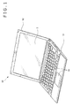
- FIG. 1 shows an external view indicative of an exemplary configuration of the information processing apparatus.
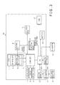
- FIG. 2 is a block diagram illustrating an exemplary internal configuration of the information processing apparatus.
- the description is made by use of an example in which the information processing apparatus is applied to a note-size PC (Personal Computer). It should be noted that the configuration shown in FIG. 1 is common to all the embodiments to be described below.
- a note-size PC 50 is made up of a main frame 51 and a display unit 52.
- the main frame 51 has a housing of a thin box, on top of which an operation input block 14 and so on made up of a keyboard, a touch panel, and so on are arranged, for example.
- a video display block 5 based on an LCD (Liquid Crystal Panel) or an organic EL (Electro Luminescence), for example, is built.
- the display unit 52 is attached to the main frame 51 pivotably between an open position and a closed position relative to the main frame 51.
- a detachable GPU 4 to be described later is mounted on the note-size PC 50 by being loaded into a slot arranged in the main frame 51, for example.
- the slot into which the detachable GPU 4 is loaded may be a general-purpose slot arranged on the main frame 51 or a slot dedicated to GPU addition.
- the detachable GPU 4 may be connected to the note-size PC 50 via a general-purpose serial bus port arranged on the note-size PC 50.
- the note-size PC 50 has a CPU (Central Processing Unit) 1 and a chip set 2.
- the CPU 1 is a control block configured to control the other components of the note-size PC 50.
- the CPU 1 executes an OS (Operating System) and various applications that are loaded from a drive 8 to be described later into a main memory, not shown.
- OS Operating System
- the CPU 1 contains an internal GPU 3 that functions as a first drawing processing block.
- the CPU 1 is connected with the detachable GPU 4 that functions as a second drawing processing block.
- the internal GPU 3 and the detachable GPU 4 generate video signals by executing drawing processing on the data received from the CPU 1.
- the video signals generated by the internal GPU 3 and the detachable GPU 4 are entered in a video signal output portion 31 in the internal GPU 3.
- the video signal output portion 31 executes various image adjustments on each of the entered video signals in order to adapt the video signals to the video display block 5, thereby outputting the image-adjusted video signals to the chip set 2.
- the chip set 2 outputs the video signals entered from the video signal output portion 31 from a video signal output terminal, not shown, to a video display block 5 or an external monitor 12 to be described later.
- the detachable GPU 4 it is assumed that, in drawing processing power, the detachable GPU 4 be higher than the internal GPU 3. Therefore, the detachable GPU 4 provides a higher drawing processing power in 3D processing and high-resolution drawing processing, for example.
- the detachable GPU 4 drives itself and peripheral devices, relatively high power dissipation will result. Therefore, when the detachable GPU 4 is operating, the power load to the entire system of the note-size PC 50 also increases. For this reason, a detachable-GPU power supply circuit 6 is connected to the detachable GPU 4. The detachable GPU 4 operates on the power supplied from the detachable-GPU power supply circuit 6.
- the detachable-GPU power supply circuit 6 switches between start and stop of supplying the power to the detachable GPU 4 on the basis of a power ON/OFF signal outputted from an EC (Embedded Controller) 10 to be described later.
- the detachable-GPU power supply circuit 6 stops the function of the detachable GPU 4, thereby stopping the power supply to the detachable GPU 4 and periphery devices. This control can hold the power dissipation of the entire note-size PC 50 to a relatively low level. It is also practicable to output, from the chip set 2, the power ON/OFF signal for switching between start and stop of supplying the power to the detachable GPU 4.
- the chip set 2 has a connection interface for supporting the connection to each peripheral device, thereby controlling the input/output of data with each peripheral device.
- the peripheral devices connected to the chip set 2 include a nonvolatile memory 7, the drive 8, an optical drive 9, and the EC 10, for example, that function as storage blocks.
- the nonvolatile memory 7 is based on ROM (Read Only Memory), EEPROM (Electrically Erasable and Programmable Read Only Memory), or a flush memory, for example.
- the drive 8 is based on HDD (Hard Disk Drive) or SSD (Solid State Drive), for example, and used as a storage for the note-size PC 50.
- the drive 8 stores various applications, which are read by the CPU 1 into a main memory, not shown, to be executed as described above. Of these applications, the drawing processing of the applications that require the drawing processing by the internal GPU 3 or the detachable GPU 4 is executed by the internal GPU 3 or the detachable GPU 4.
- the information processing apparatus (the note-size PC 50) disclosed herein executes the dynamic selection and assignment of each GPU on which applications are executed, by various techniques as described below in the embodiments of the disclosure.
- the optical drive 9 is made up of a DVD (Digital Versatile Disc) drive or a Blu-ray disc drive, for example.
- the EC 10 is connected with a connection detection block 13 for detecting the connection of the external monitor 12 to a connector 11, an operation input block 14, an AC adaptor 15, a battery 16, a fan 17, and the above-mentioned detachable-GPU power supply circuit 6 and controls these components.
- the EC 10 has KBC (Keyboard Controller) for controlling the operation input block 14 and the ACPI/EC function for executing power supply management compliant with ACPI (Advanced Configuration and Power Interface) that is a standard associated with power control.
- KBC Keyboard Controller
- the EC 10 has a shared memory space for transferring data with BIOS (Basic Input/Output System), thereby transferring commands and data with BIOS.
- BIOS is firmware for executing data input/output processing in the hardware of the information processing apparatus (the note-size PC 50).
- the EC 10 generates a power ON/OFF control signal for switching between the power ON/OFF of the detachable GPU 4 and supplies the generated power ON/OFF control signal to the detachable-GPU power supply circuit 6.
- the external monitor 12 may also be connected to the note-size PC 50 herein.
- the external monitor 12 is a display based on LCD or organic EL, for example, which is connected to the note-size PC 50 via the connector 11 by means of a DVI (Digital Visual Interface) terminal or an HDMI (High-Definition Multimedia Interface) terminal, for example.
- DVI Digital Visual Interface
- HDMI High-Definition Multimedia Interface
- the operation input block 14 is made up of a keyboard, a touch pad, and a mouse, for example, generates an operation signal corresponding to an operation done by the user, and supplies the generated operation signal to the EC 10.
- the AC adaptor 15 converts a commercial alternating-current power into a direct-current power and supplies the direct-current power to the note-size PC 50.
- the battery 16 is a secondary battery built in the note-size PC 50 and supplies power to each component of the note-size PC 50 in a state where the AC adaptor 15 is not connected to the note-size PC 50.
- the fan 17 is a mechanism configured to dissipate the heat generated from the CPU 1 and so on. It should be noted that the EC 10 may control such that the rotation of the fan 17 differs between the case where the internal GPU 3 is selected and the case where the detachable GPU 4 is selected. For example, if the internal GPU 3 is selected, the rotation of the fan 17 may be lowered than that if the detachable GPU 4 is selected. This rotation control allows the further lowering of the power dissipation of the note-size PC 50.
- execution of the internal GPU 3 or the detachable GPU 4 denotes to make one of the GPUs execute drawing processing by controlling the power supply to the GPUs.
- note-size PC 50 have such functions and devices necessary for the operation of the computer as various interfaces including buses and terminals, in addition to the component blocks mentioned above.
- FIG. 2 the configuration between the EC 10 and the peripheral blocks thereof is shown only in a control configuration as viewed from the EC 10; for example, a supply path of video signals to the external monitor 12 and power supply paths from the AC adaptor 15 and the battery 16 are omitted.
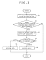
- step S1 when an application is launched on the basis of an operation done by the user through the operation input block 14 (step S1), the CPU 1 determines whether the launched application requires a high graphics processing performance or not (step S2). If the launched application is found not requiring a GPU power (processing performance), namely, if the launched application is found to be a text editor for example, then "NO" is selected in step S2, upon which the processing comes to an end.
- the CPU 1 that operates as a workload measuring block measures the workloads in the iGPU 3 and dGPU 4 (step S3).
- the workload of each GPU is measured by the magnitude of the power dissipation in each GPU and the height of the temperature (the junction plane temperature) of the chip junction plane of the semiconductor of each of the iGPU 3 and dGPU 4, for example.
- the actual measurement values of power dissipation and junction plane temperature are the same between the iGPU 3 and the dGPU 4, the magnitudes of workloads of the iGPU 3 and the dGPU 4 are different. Therefore, the actual measurement values are related with the load ratios in advance such that, at the same X degrees centigrade, the workload is 50% for the iGPU 3 and 20% for the dGPU 4, for example, thereby determining the magnitude of workload by load ratio.
- the CPU 1 determines the GPU that is lower in workload (step S4). If the magnitude of workload is measured by junction plane temperature, it is possible to determine, as the GPU lower in workload, the GPU having a greater difference between the absolute maximum rating of junction plane temperature and the measured junction plane temperature, for example.
- step S4 If the GPU lower in workload is found to be the dGPU 4 as a result of the decision made in step S4, then control is executed to assign the dGPU 4 for the GPU for executing the application (step S5). If the workload of the iGPU 3 is found lower, then control is executed to assign the iGPU 3 as the GPU for executing the application (step S6).
- the one lower in workload is automatically selected for the GPU that executes an application.
- the workload of the detachable GPU 4 executing the 3D game be already high, so that the processing of step S6 is executed as a result of the decision of step S4.
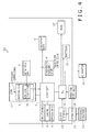
- FIG. 4 describes an exemplary configuration of an information processing apparatus practiced as the second embodiment of the disclosure with reference to the block diagram shown in FIG. 4 .
- a frequency control signal for controlling an operation clock frequency is supplied.
- This frequency control signal is an instruction for bringing the operation clock frequency of the internal GPU 3 to less than a predetermined clock.
- a minimum frequency for example at which the internal GPU 3 can operate is set. If the frequency control signal having the control value that is this minimum frequency for example is not outputted, the control value is set to an operation clock frequency at which the internal GPU 3 can exert the original power thereof.
- Supplying the frequency control signal to the internal GPU 3 is executed in a software approach by arranging a dedicated API (Application Program Interface) for example and through the arranged API.
- a dedicated API Application Program Interface
- a physical signal pin may be arranged for each integrated circuit making up the internal GPU 3 to apply the frequency control signal to this signal pin.
- the frequency control signal is transmitted from the CPU 1 to the internal GPU 3 when the power is being supplied only from the battery 16 or "power save mode" is set.
- Power save mode herein denotes the saving of the power by invalidating, reducing, or simplifying predetermined functions or devices (for example, functions and devices that are comparatively less influenced by the operation of a user computer).
- step S11 when a new application is launched in response to an operation done by the user through the operation input block 14 (step S11), the CPU 1 determines whether the note-size PC 50 is operating on the battery 16 or in the power save mode (step S12). If the note-size PC 50 is found to be operating neither on the battery 16 nor in the power save mode, then the processing comes to an end.
- step S11 the application newly launched in step S11 is executed by the iGPU 3 (step S13) and a frequency control signal is transmitted to the iGPU 3 to limit the operation clock frequency to less than a predetermined clock (step S14).
- the newly launched applications requiring the GPU processing power are all executed in the internal GPU 3 while the note-size PC 50 is operating on the battery 16 or in the power save mode. Consequently, in a situation where it is necessary to reduce the power dissipation of the note-size PC 50, the newly launched applications are prevent from being executed by the detachable GPU 4 that is high in power dissipation. Further, controlling the operation frequency of the internal GPU 3 to be held below a predetermined frequency allows the more reduction of the power dissipation.
- the processing shown in FIG. 5 is executed when the note-size PC 50 is operating on the battery 16 or in the power save mode; however, the present embodiment is not limited thereto. Even if the note-size PC 50 is operating on the battery 16, the processing shown in FIG. 5 may not be executed when the amount of charge of the battery 16 is sufficient (that is, more than a predetermined amount). To be more specific, the control may be varied in accordance with the remaining level of the battery 16.
- FIG. 6 describes an exemplary configuration of an information processing apparatus practiced as the third embodiment of the disclosure with reference to the block diagram shown in FIG. 6 .
- components previously described with reference to FIG. 2 (and FIG. 4 ) are denoted by the same reference numerals and the duplicate description will be skipped.
- a difference from the configuration shown in FIG. 2 lies in that an "application Vs. GPU table T1" indicative of the relation between various applications and the GPUs on which these applications are executed is stored in a nonvolatile memory 7.
- the application Vs. GPU table T1 is stored in the nonvolatile memory 7; however it is not limited to this and it is also practicable to store this table in a drive 8.
- “category a” and “category b” as a first category the GPU on which applications are executed is statically set in advance. These applications which makes the most of the functions unique to the internal GPU 3 or the detachable GPU 4 are put in these categories.
- “category a” an application that wirelessly transfers the content stored in the note-size PC 50 or on the Internet to a television receiver and displays the transferred content thereon, for example, is stored.
- category a a program developed by use of GP GPU (General Purpose computing on GPU), a simulation software program of physical computation system for example, is sorted.
- categories c and d are sorted, for example.
- categories d are sorted, for example.
- categories d are sorted.
- categories e are sorted.
- 3D reproducing applications that are not heavy in processing are sorted among the 3D game reproducing applications.
- step S21 when a new application is launched by an operation done by the user through the operation input block 14 (step S21), then the CPU 1 checks in which category the launched application is sorted (step S22). If the launched application is found to have been sorted in category a, namely, if the launched application is an application statically related with the iGPU 3 (the internal GPU 3), then the iGPU 3 is assigned as the GPU on which this application is executed (step S23). If the launched application is found to have been sorted in category b, namely, if the launched application is an application statically assigned to the dGPU 4 (the detachable GPU 4), then the dGPU is assigned (step S24).
- the CPU 1 measures the workload of the iGPU 3 (step S25). Next, CPU 1 determines whether the measured workload is in excess of a predetermined level or not (step S26). If the measured workload is found to be lower than the predetermined level, then the iGPU 3 is assigned on which the application is executed (step S27). If the measured workload is found to be in excess of the predetermined level, then the dGPU 4 is assigned rather than the iGPU 3 (step S28).
- the CPU 1 first measures the workload of the dGPU 4 (step S29). Next, the CPU 1 determines whether the measured workload is in excess of a predetermined level or not (step S30). If the measured workload is found to be below the predetermined level, then the dGPU 4 is assigned as the GPU on which the application is executed (step S31). If the measured workload is found to be in excess of the predetermined level, then the iGPU 3, rather than the dGPU 4, is assigned as the GPU on which the application is executed (step S32).
- the CPU 1 measures the workloads of both the iGPU 3 and the dGPU 4 (step S33). Next, the CPU 1 determines which of the iGPU 3 and the dGPU 4 has a lower workload (step S34). If the workload of the iGPU 3 is lower than that of the dGPU 4, the iGPU 3 is assigned (step S35). If the workload of the dGPU 4 is lower than that of the iGPU 3, then the dGPU 4 is assigned (step S36).
- the GPU has possibly no room for executing a new application in assigning the GPU in step S28, S32, or S36. If the GPU is found to have no room for executing a new application, it indicates that the power dissipation and/or the junction plane temperature has reached the upper limit thereof, for example. If this happens, the present embodiment is configured to issue an alert message for prompting the user to discontinue the application being executed or delay the launching of a new application.
- the applications found to have been sorted in "category c" and “category d” are executed on the GPU which is desirable for these applications to be executed on if the workload of such a GPU is lower than a predetermined level. If the workload of the GPU which is desirable for these applications to be executed on is found to be in excess of a predetermined level, then these applications are executed on the other GPU. Applications sorted in “category e” are executed on the internal GPU 3 or the detachable GPU 4 whichever is lower in workload. This prevents a situation in which only one of the GPUs is always selected depending on the types of application to be executed. To be more specific, the workloads of the GPUs are distributed in between, and the execution efficiency of applications executed on the GPUs is enhanced.
- the applications sorted in "category a" and “category b" are executed always on the GPUs related in advance in any situation; however, the present embodiment is not limited thereto.
- an application of "category b" related with the execution on the detachable GPU 4 may be executed on the internal GPU 3.
- this control is executed, the application may not operate correctly in some cases. If such a situation is predicted, the user is noticed in advance that the application may not operate correctly.
- FIG. 8 shows a flowchart indicative of an exemplary operation of the note-size PC 50 to be executed when the above-mentioned processing is executed.
- the CPU 1 determines whether the note-size PC 50 is operating on the battery 16 or in the power save mode (step S42). If the note-size PC 50 is found to be operating on the battery 16 or in the power save mode, this application is assigned to the iGPU 3 and, at the same time, the operation clock frequency of the iGPU 3 is limited to a level below a predetermined frequency (step S43).
- step S42 If the note-size PC 50 is found to be operating neither on the battery 16 nor in the power save mode in step S42, then the CPU 1 checks which category the launched application is sorted in (step S44).
- the processing operations to be executed in subsequent steps S45 through S58 are the same as those of steps S23 through S36 shown in FIG. 7 , so that the description thereof will be skipped.
- Executing the above-mentioned control processing prevents the application from being executed on the detachable GPU 4 of high power dissipation in a situation where the power dissipation of the note-size PC 50 needs to be held low. Further, by also limiting the operation clock frequency of the internal GPU 3, the power dissipation of the note-size PC 50 can be further held low.
- the applications to be listed in the "application Vs. GPU table T1" have already been installed in the note-size PC 50 (or in the nonvolatile memory 7), for example.
- the third embodiment is not limited thereto. It is also practicable to apply the categories described above every time a new application is installed by the user, thereby switching between the GPUs in accordance with the categories.
- FIG. 9 shows an exemplary configuration of the note-size PC 50 that is configured as described above.
- the nonvolatile memory 7 further stores an application characteristics information database D1 and a benchmark software program S1.
- the application characteristics information database D1 stores information about a workload to be applied to each GPU at the execution of an application as application characteristics information.
- Information about the workload to be applied to each GPU at the execution of an application can be obtained by executing a predetermined application in a benchmark mode by use of the benchmark software program S1 designed to reproduce a particular load situation.
- the processing powers and power dissipations of the internal GPU 3 and the detachable GPU 4 are stored in the application characteristics information database D1.
- the application Vs. GPU table T1 described with the third embodiment is configured.
- the actual assignment of the GPUs is executed.
- Carrying out the configuration and the processing as described above allows the execution of not only applications already stored in the nonvolatile memory 7 but also applications newly installed on the note-size PC 50 by the GPU suitable for the characteristics of these applications.
- the benchmark software program S1 suitable for measuring the workload applied to each GPU at the execution of an application is not installed on the note-size PC 50, then the measuring data obtained while an application is actually being executed may be used.
- the actual measurement values of the processing powers and power dissipations of the internal GPU 3 and the detachable GPU 4 during the execution of an application may be reflected on the application characteristics information database D1. This configuration provides substantially the same effects as those obtained by the measurement based on the benchmark software program S1.
- the application characteristics information database D1 may be accumulated in a network server, not shown, for example.
- the user downloads the characteristics information of this application from the network server. Then, the user updates the application Vs. GPU table T1 installed on the note-size PC 50 by use of the downloaded characteristics information. Consequently, at the execution of the newly installed application, the GPU suitable for the characteristics of this application is automatically selected on the basis of the information listed on the application Vs. GPU table T1.
- the application characteristics information database D1 on the network server is constructed by personal computer vendors, application vendors, or given users configured beforehand and the constructed database can be updated by these members from time to time.
- Carrying out the configuration and the processing as described above saves the user when installing a new application on the note-size PC 50 to execute this new application in the benchmark mode.
- the characteristics information of the application downloaded from the network server is added to the application Vs.
- GPU table T1 and on the basis of the information in this table, the GPU suitable for the characteristics of the installed application can be selected automatically.
- the present disclosure contains subject matter related to that disclosed in Japanese Priority Patent Application JP 2011-129191 .
Applications Claiming Priority (1)
| Application Number | Priority Date | Filing Date | Title |
|---|---|---|---|
| JP2011129191A JP2012256223A (ja) | 2011-06-09 | 2011-06-09 | 情報処理装置および情報処理方法 |
Publications (1)
| Publication Number | Publication Date |
|---|---|
| EP2533236A1 true EP2533236A1 (en) | 2012-12-12 |
Family
ID=46456300
Family Applications (1)
| Application Number | Title | Priority Date | Filing Date |
|---|---|---|---|
| EP12163867A Withdrawn EP2533236A1 (en) | 2011-06-09 | 2012-04-12 | Information processing apparatus with multiple drawing processing blocks and information processing method |
Country Status (4)
| Country | Link |
|---|---|
| US (1) | US8947443B2 (ja) |
| EP (1) | EP2533236A1 (ja) |
| JP (1) | JP2012256223A (ja) |
| CN (1) | CN102981592A (ja) |
Cited By (1)
| Publication number | Priority date | Publication date | Assignee | Title |
|---|---|---|---|---|
| GB2611143A (en) * | 2021-09-28 | 2023-03-29 | Lenovo Beijing Ltd | Electronic device |
Families Citing this family (10)
| Publication number | Priority date | Publication date | Assignee | Title |
|---|---|---|---|---|
| CN103988190A (zh) * | 2011-12-16 | 2014-08-13 | 英特尔公司 | 用于通过外部显示-数据i/o端口来扩展图形处理的方法、设备及系统 |
| KR20140114501A (ko) * | 2013-03-14 | 2014-09-29 | 삼성전자주식회사 | 영상 데이터 처리 방법 및 이를 지원하는 전자 장치 |
| JP6337494B2 (ja) * | 2013-07-08 | 2018-06-06 | 株式会社リコー | 画像処理装置、画像処理方法、及びプログラム |
| JP6119498B2 (ja) * | 2013-08-07 | 2017-04-26 | 富士ゼロックス株式会社 | マルチコアプロセッサ、画像形成装置およびプログラム |
| CN105446462B (zh) * | 2014-06-27 | 2020-12-18 | 联想(北京)有限公司 | 一种显示方法、装置、电路及电子设备 |
| KR101655027B1 (ko) * | 2015-04-22 | 2016-09-06 | 한양대학교 산학협력단 | 전자 기기의 유효 작업부하 결정 방법 및 장치 |
| KR101780059B1 (ko) * | 2015-07-02 | 2017-09-19 | 가온미디어 주식회사 | 디지털 방송재생장치에서 시나리오 기반의 소비전력 제어 방법 |
| JP6617388B1 (ja) | 2018-06-21 | 2019-12-11 | レノボ・シンガポール・プライベート・リミテッド | 情報処理装置、映像表示装置、および映像表示システム |
| US11107181B2 (en) * | 2018-11-15 | 2021-08-31 | Arizona Board Of Regents On Behalf Of Arizona State University | Fidelity-driven runtime thermal management for near-sensor architectures |
| US20220253124A1 (en) * | 2019-08-20 | 2022-08-11 | Intel Corporation | Apparatus and method to improve switchable graphics system performance and energy consumption based applications and real-time system power/thermal budgets |
Citations (9)
| Publication number | Priority date | Publication date | Assignee | Title |
|---|---|---|---|---|
| JPH11353495A (ja) * | 1998-06-10 | 1999-12-24 | Nec Corp | グラフィックス装置とグラフィック方法 |
| US20040085322A1 (en) * | 2002-10-30 | 2004-05-06 | Alcorn Byron A. | System and method for performing BLTs |
| US20050041031A1 (en) * | 2003-08-18 | 2005-02-24 | Nvidia Corporation | Adaptive load balancing in a multi-processor graphics processing system |
| JP2007179225A (ja) | 2005-12-27 | 2007-07-12 | Sony Corp | 情報処理装置、情報処理方法及びそのプログラム |
| WO2009038902A1 (en) * | 2007-09-20 | 2009-03-26 | Apple Inc. | Switching between graphics sources to facilitate power management and/or security |
| EP2079015A1 (en) * | 2008-01-10 | 2009-07-15 | LG Electronics Inc. | Data processing unit with multi-graphic controller and method for processing data using the same |
| JP2010020596A (ja) | 2008-07-11 | 2010-01-28 | Sony Corp | 情報処理装置、情報処理方法及びそのプログラム |
| US20100332799A1 (en) * | 2009-06-30 | 2010-12-30 | Hajime Sonobe | Image processing apparatus and image processing method |
| JP2011129191A (ja) | 2009-12-16 | 2011-06-30 | Toshiba Corp | 取付金具および電子機器 |
Family Cites Families (4)
| Publication number | Priority date | Publication date | Assignee | Title |
|---|---|---|---|---|
| JP2002117396A (ja) * | 2000-10-05 | 2002-04-19 | Ricoh Co Ltd | 画像処理装置 |
| JP3867888B2 (ja) * | 2000-10-18 | 2007-01-17 | 株式会社リコー | 画像情報の回転方法,回転装置,記録媒体,画像読取装置および画像形成装置 |
| TW200949755A (en) * | 2008-05-30 | 2009-12-01 | Asustek Comp Inc | Method of controlling operation mode of graphic processing unit |
| US9542914B2 (en) * | 2008-12-31 | 2017-01-10 | Apple Inc. | Display system with improved graphics abilities while switching graphics processing units |
-
2011
- 2011-06-09 JP JP2011129191A patent/JP2012256223A/ja not_active Abandoned
-
2012
- 2012-04-12 EP EP12163867A patent/EP2533236A1/en not_active Withdrawn
- 2012-05-31 US US13/484,617 patent/US8947443B2/en not_active Expired - Fee Related
- 2012-06-01 CN CN2012101800749A patent/CN102981592A/zh active Pending
Patent Citations (9)
| Publication number | Priority date | Publication date | Assignee | Title |
|---|---|---|---|---|
| JPH11353495A (ja) * | 1998-06-10 | 1999-12-24 | Nec Corp | グラフィックス装置とグラフィック方法 |
| US20040085322A1 (en) * | 2002-10-30 | 2004-05-06 | Alcorn Byron A. | System and method for performing BLTs |
| US20050041031A1 (en) * | 2003-08-18 | 2005-02-24 | Nvidia Corporation | Adaptive load balancing in a multi-processor graphics processing system |
| JP2007179225A (ja) | 2005-12-27 | 2007-07-12 | Sony Corp | 情報処理装置、情報処理方法及びそのプログラム |
| WO2009038902A1 (en) * | 2007-09-20 | 2009-03-26 | Apple Inc. | Switching between graphics sources to facilitate power management and/or security |
| EP2079015A1 (en) * | 2008-01-10 | 2009-07-15 | LG Electronics Inc. | Data processing unit with multi-graphic controller and method for processing data using the same |
| JP2010020596A (ja) | 2008-07-11 | 2010-01-28 | Sony Corp | 情報処理装置、情報処理方法及びそのプログラム |
| US20100332799A1 (en) * | 2009-06-30 | 2010-12-30 | Hajime Sonobe | Image processing apparatus and image processing method |
| JP2011129191A (ja) | 2009-12-16 | 2011-06-30 | Toshiba Corp | 取付金具および電子機器 |
Non-Patent Citations (1)
| Title |
|---|
| BYEONG-GYU NAM ET AL: "Cost-effective low-power graphics processing unit for handheld devices [integrated circuits for communications]", IEEE COMMUNICATIONS MAGAZINE, IEEE SERVICE CENTER, PISCATAWAY, US, vol. 46, no. 4, 1 April 2008 (2008-04-01), pages 152 - 159, XP011206964, ISSN: 0163-6804 * |
Cited By (1)
| Publication number | Priority date | Publication date | Assignee | Title |
|---|---|---|---|---|
| GB2611143A (en) * | 2021-09-28 | 2023-03-29 | Lenovo Beijing Ltd | Electronic device |
Also Published As
| Publication number | Publication date |
|---|---|
| JP2012256223A (ja) | 2012-12-27 |
| CN102981592A (zh) | 2013-03-20 |
| US8947443B2 (en) | 2015-02-03 |
| US20120313952A1 (en) | 2012-12-13 |
Similar Documents
| Publication | Publication Date | Title |
|---|---|---|
| US8947443B2 (en) | Information processing apparatus and information processing method | |
| EP2428948B1 (en) | Device having multiple graphics subsystems and reduced power consumption mode, software and methods | |
| US8555099B2 (en) | Device having multiple graphics subsystems and reduced power consumption mode, software and methods | |
| JP4937752B2 (ja) | 電力管理イベントの検出によるディスプレイ更新特性の切り替え | |
| US20080084189A1 (en) | Computer system and control method thereof capable of changing battery charging mode according to user's selection | |
| JP2014106882A (ja) | 情報処理装置及び表示制御方法 | |
| US9070333B2 (en) | Information processing apparatus, information processing method, and program | |
| KR102226798B1 (ko) | 전자 장치 | |
| US20140089696A1 (en) | Method for controlling power mode switching | |
| US20150153804A1 (en) | Information processing apparatus and operation control method | |
| JP6982647B2 (ja) | 情報処理装置、及び制御方法 | |
| JP4410215B2 (ja) | 消費電力の制御方法およびコンピュータ装置 | |
| US20220317756A1 (en) | Graphics processing unit (gpu) selection based on a utilized power source | |
| JP5439571B2 (ja) | 情報処理装置および動作制御方法 | |
| EP3430700B1 (en) | Provide bounded voltage range | |
| US20080309682A1 (en) | System and method of boosting lamp luminance in a laptop computing device | |
| JP2009009183A (ja) | 電子機器、電子機器の電源制御方法、およびコンピュータが実行するためのプログラム |
Legal Events
| Date | Code | Title | Description |
|---|---|---|---|
| PUAI | Public reference made under article 153(3) epc to a published international application that has entered the european phase |
Free format text: ORIGINAL CODE: 0009012 |
|
| 17P | Request for examination filed |
Effective date: 20120412 |
|
| AK | Designated contracting states |
Kind code of ref document: A1 Designated state(s): AL AT BE BG CH CY CZ DE DK EE ES FI FR GB GR HR HU IE IS IT LI LT LU LV MC MK MT NL NO PL PT RO RS SE SI SK SM TR |
|
| AX | Request for extension of the european patent |
Extension state: BA ME |
|
| STAA | Information on the status of an ep patent application or granted ep patent |
Free format text: STATUS: THE APPLICATION HAS BEEN WITHDRAWN |
|
| 18W | Application withdrawn |
Effective date: 20150107 |