EP2532876A1 - Fuel supply device - Google Patents
Fuel supply device Download PDFInfo
- Publication number
- EP2532876A1 EP2532876A1 EP11739868A EP11739868A EP2532876A1 EP 2532876 A1 EP2532876 A1 EP 2532876A1 EP 11739868 A EP11739868 A EP 11739868A EP 11739868 A EP11739868 A EP 11739868A EP 2532876 A1 EP2532876 A1 EP 2532876A1
- Authority
- EP
- European Patent Office
- Prior art keywords
- section
- engagement
- fuel
- suction
- fuel pump
- Prior art date
- Legal status (The legal status is an assumption and is not a legal conclusion. Google has not performed a legal analysis and makes no representation as to the accuracy of the status listed.)
- Granted
Links
- 239000000446 fuel Substances 0.000 title claims abstract description 180
- 230000007246 mechanism Effects 0.000 claims abstract description 11
- 239000002828 fuel tank Substances 0.000 claims description 22
- 230000002265 prevention Effects 0.000 claims description 19
- 230000002093 peripheral effect Effects 0.000 claims description 16
- 238000002485 combustion reaction Methods 0.000 claims description 5
- 238000005086 pumping Methods 0.000 claims description 4
- 210000000078 claw Anatomy 0.000 description 118
- 230000000630 rising effect Effects 0.000 description 12
- 239000002184 metal Substances 0.000 description 9
- 238000010586 diagram Methods 0.000 description 7
- 238000001914 filtration Methods 0.000 description 7
- 238000000034 method Methods 0.000 description 7
- 238000003466 welding Methods 0.000 description 5
- 238000007872 degassing Methods 0.000 description 4
- 239000011347 resin Substances 0.000 description 4
- 229920005989 resin Polymers 0.000 description 4
- 230000005489 elastic deformation Effects 0.000 description 3
- 238000000605 extraction Methods 0.000 description 3
- 239000007788 liquid Substances 0.000 description 3
- 238000004519 manufacturing process Methods 0.000 description 3
- 230000000694 effects Effects 0.000 description 2
- 238000006073 displacement reaction Methods 0.000 description 1
- 239000004745 nonwoven fabric Substances 0.000 description 1
- 230000001172 regenerating effect Effects 0.000 description 1
- 238000007789 sealing Methods 0.000 description 1
Images


Classifications
-
- F—MECHANICAL ENGINEERING; LIGHTING; HEATING; WEAPONS; BLASTING
- F02—COMBUSTION ENGINES; HOT-GAS OR COMBUSTION-PRODUCT ENGINE PLANTS
- F02M—SUPPLYING COMBUSTION ENGINES IN GENERAL WITH COMBUSTIBLE MIXTURES OR CONSTITUENTS THEREOF
- F02M37/00—Apparatus or systems for feeding liquid fuel from storage containers to carburettors or fuel-injection apparatus; Arrangements for purifying liquid fuel specially adapted for, or arranged on, internal-combustion engines
- F02M37/04—Feeding by means of driven pumps
- F02M37/08—Feeding by means of driven pumps electrically driven
- F02M37/10—Feeding by means of driven pumps electrically driven submerged in fuel, e.g. in reservoir
- F02M37/103—Mounting pumps on fuel tanks
-
- B—PERFORMING OPERATIONS; TRANSPORTING
- B01—PHYSICAL OR CHEMICAL PROCESSES OR APPARATUS IN GENERAL
- B01D—SEPARATION
- B01D35/00—Filtering devices having features not specifically covered by groups B01D24/00 - B01D33/00, or for applications not specifically covered by groups B01D24/00 - B01D33/00; Auxiliary devices for filtration; Filter housing constructions
- B01D35/02—Filters adapted for location in special places, e.g. pipe-lines, pumps, stop-cocks
- B01D35/027—Filters adapted for location in special places, e.g. pipe-lines, pumps, stop-cocks rigidly mounted in or on tanks or reservoirs
- B01D35/0273—Filtering elements with a horizontal or inclined rotation or symmetry axis submerged in tanks or reservoirs
-
- B—PERFORMING OPERATIONS; TRANSPORTING
- B01—PHYSICAL OR CHEMICAL PROCESSES OR APPARATUS IN GENERAL
- B01D—SEPARATION
- B01D35/00—Filtering devices having features not specifically covered by groups B01D24/00 - B01D33/00, or for applications not specifically covered by groups B01D24/00 - B01D33/00; Auxiliary devices for filtration; Filter housing constructions
- B01D35/26—Filters with built-in pumps filters provided with a pump mounted in or on the casing
-
- F—MECHANICAL ENGINEERING; LIGHTING; HEATING; WEAPONS; BLASTING
- F02—COMBUSTION ENGINES; HOT-GAS OR COMBUSTION-PRODUCT ENGINE PLANTS
- F02M—SUPPLYING COMBUSTION ENGINES IN GENERAL WITH COMBUSTIBLE MIXTURES OR CONSTITUENTS THEREOF
- F02M37/00—Apparatus or systems for feeding liquid fuel from storage containers to carburettors or fuel-injection apparatus; Arrangements for purifying liquid fuel specially adapted for, or arranged on, internal-combustion engines
- F02M37/22—Arrangements for purifying liquid fuel specially adapted for, or arranged on, internal-combustion engines, e.g. arrangements in the feeding system
- F02M37/32—Arrangements for purifying liquid fuel specially adapted for, or arranged on, internal-combustion engines, e.g. arrangements in the feeding system characterised by filters or filter arrangements
- F02M37/44—Filters structurally associated with pumps
-
- F—MECHANICAL ENGINEERING; LIGHTING; HEATING; WEAPONS; BLASTING
- F02—COMBUSTION ENGINES; HOT-GAS OR COMBUSTION-PRODUCT ENGINE PLANTS
- F02M—SUPPLYING COMBUSTION ENGINES IN GENERAL WITH COMBUSTIBLE MIXTURES OR CONSTITUENTS THEREOF
- F02M37/00—Apparatus or systems for feeding liquid fuel from storage containers to carburettors or fuel-injection apparatus; Arrangements for purifying liquid fuel specially adapted for, or arranged on, internal-combustion engines
- F02M37/22—Arrangements for purifying liquid fuel specially adapted for, or arranged on, internal-combustion engines, e.g. arrangements in the feeding system
- F02M37/32—Arrangements for purifying liquid fuel specially adapted for, or arranged on, internal-combustion engines, e.g. arrangements in the feeding system characterised by filters or filter arrangements
- F02M37/50—Filters arranged in or on fuel tanks
Definitions
- the present invention relates to a fuel supply device.
- Priority is claimed on Japanese Patent Application No. 2010-023478 filed on February 4, 2010 , the content of which is incorporated herein by reference.
- a so-called in-tank type in which a fuel pump is disposed in a fuel tank and a fuel supply device is immersed in fuel in the fuel tank.
- a pump section which pumps up fuel, thereby pumping the fuel to an internal-combustion engine (an engine), is provided on the bottom surface side of the fuel tank.
- a motor section which drives the pump section is provided, and a suction filter (a filter) is attached to the bottom of the pump section through a fuel suction port (a fuel suction section).
- the suction filter filters fuel which is pumped up by the pump section, thereby preventing foreign matters in the fuel tank from entering to the pump section.
- a technique is disclosed in which a pipe which can be connected to the fuel suction section is provided, and a projection provided at the fuel suction section in the vicinity of a suction port of the pump section is fixed to a flange section integrally provided on the outer circumferential surface of the pipe through a metal bracket (refer to Patent Document 1, for example).
- a metal bracket In the metal bracket, an engagement hole in which the projection can be inserted is provided. At a peripheral edge of the engagement hole, a plurality of claws is formed. These claws play a role as retainers preventing the projection falling-out when the projection is inserted into the engagement hole.
- a mounting hole is formed at a site corresponding to the engagement hole. Then, the metal bracket is swaged and fixed to the flange section by using a jig in a state where the mounting hole of the flange section and the engagement hole of the metal bracket overlap each other. In this manner, it is attempted to improve the attachment workability of the suction filter by fixing the projection of the pump section through the metal bracket.
- the present invention has been made in view of the above-described problems and has an object to provide a fuel supply device which allows the work of attaching and dismounting a suction filter to be easily performed without increasing the number of components.
- the present invention adopts the following configurations in order to solve the above problems, thereby achieving a relevant object.
- each of the fuel suction section and the connection section may have a tubular shape and also the connection section may be connected to the fuel suction section, and the fixing mechanisms may include a first engagement section provided on the outer circumferential surface of the connection section, and a second engagement section which is formed at the fuel pump unit and accepts the first engagement section from a circumferential direction, thereby being engaged with the first engagement section.
- the first engagement section may extend in a circumferential direction of the connection section, be elastically deformable, and be provided with a projection which restricts falling-out from the second engagement section.
- the projection may be disposed at a middle position in a longitudinal direction of the first engagement section, and a portion further on the leading end side than the projection of the first engagement section may form an input portion which accepts an external force when elastically deforming the first engagement section.
- At least one of the input portions may protrude further to the outside in a radial direction than the outer circumferential surface of the fuel pump unit in a state where the connection section has been connected to the fuel suction section.
- the fuel supply device may further include: a convex portion for preventing incorrect attachment provided at one of an outer peripheral edge on the fuel pump unit side of the connection section and the fuel pump unit; and a groove portion which is provided at other one of the outer peripheral edge on the fuel pump unit side of the connection section and the fuel pump unit, and in which the convex portion for preventing incorrect attachment can be fitted, wherein the size in a circumferential direction of the groove portion may be set so as to permit the turning around the axis of the convex portion for preventing incorrect attachment only by a predetermined range.
- the first engagement section may be provided in a pair at positions which are point-symmetrical with an axis of the connection section as the center, and also the projection may be provided in a protruding state on the radially inner surface side of each of the first engagement sections, the surface on the front side in a direction of rotation of each of the projections may form a first inclined surface which is orthogonal to the direction of rotation or is inclined toward the direction of rotation as it goes to the inside in a radial direction, the second engagement section may be provided in a pair at the fuel pump unit, a concave portion which accepts each of the first engagement sections may be formed on the base end side of each of the second engagement sections, while a falling-out prevention wall which restricts the falling-out in an axial direction of each of the first engagement sections inserted into the concave portion may be formed on the leading end side of each of the second engagement sections, and the side surface on the side accepting each first engagement section, of each of the falling-out prevention
- connection section of the suction filter if in a state where the connection section of the suction filter is coaxially connected to the fuel suction section provided at the fuel pump unit, the connection section is rotated around the axis thereof, the fuel suction section and the connection section cooperate with each other, whereby the connection state of the connection section is maintained. For this reason, there is no need to separately prepare a member such as a metal bracket for fixing the suction filter in attaching the connection section of the suction filter to a fuel suction port, so that it is possible to reduce the number of components. Further, since the suction filter is directly attached to the fuel suction port, it is possible to easily perform the attaching and dismounting work of the suction filter without using a jig. Accordingly, it is possible to improve the workability of attaching the suction filter to the fuel suction port.
- the first engagement section can be easily engaged with the second engagement section by rotating the connection section around the axis in a state where the connection section is connected to the fuel suction section. Further, since it is possible to make the fixing mechanisms be a simple structure, the manufacturing cost of the fuel supply device can be reduced.
- the first engagement section extends in the circumferential direction of the tubular connection section, even if the first engagement section is formed at a length required to engage with the second engagement section, the first engagement section does not protrude in the direction of the axis. For this reason, it is possible to reduce the length of the connection section in the axis direction thereof. Further, the first engagement section is provided with the projection which restricts falling-out from the second engagement section, whereby dropping-out of the fuel suction section from the connection section can be reliably prevented.
- the portion further on the leading end side than the projection of the first engagement section forms the input portion which accepts an external force when elastically deforming the first engagement section. Due to this configuration, the input portion acts as a power point for elastically deforming the first engagement section and is located at a position farther from a supporting point than the projection that is a point of action. For this reason, it is possible to separate the projection from the second engagement section by elastically deforming the first engagement section by applying to the input portion a smaller external force than the case of directly applying an external force with the projection as a power point. In this way, it is possible to easily release the engagement state of the first engagement section and the second engagement section. Accordingly, it is possible to improve the dismounting performance of the suction filter.
- the size in a circumferential direction of the groove portion is set so as to permit the turning around the axis of the convex portion for preventing incorrect attachment only by a predetermined range. For this reason, in a case where the connection section is not mounted on the fuel suction section in a given direction, the convex portion for preventing incorrect attachment is not fitted into the groove portion. As a result, at the time of attaching the suction filter, since the first engagement section of the connection section is not externally fitted to the second engagement section of the fuel suction section until the first engagement section is located at a completely connectable position, it is possible to prevent incorrect attachment of the suction filter.
- connection section in a case where the connection section is wrongly attached to the fuel suction section, even if the surface on the front side in a direction of rotation of the projection comes into contact with the falling-out prevention wall of the second engagement section, a radially outward force does not act on the first engagement section.
- the surface on the front side in a direction of rotation of the projection of the first engagement section forms the first inclined surface which is orthogonal to the direction of rotation or is inclined toward the direction of rotation as it goes to the inside in the radial direction
- the side surface on the side accepting the first engagement section, of the falling-out prevention wall forms the second inclined surface which is orthogonal to the direction of rotation or is inclined toward the opposite side to the direction of rotation as it goes to the outside in the radial direction.
- the radially outward elastic deformation of the first engagement section is prevented.
- the projection of the first engagement section can be prevented from being placed on the leading end of the second engagement section, so that it becomes possible to reliably prevent incorrect attachment of the connection section.
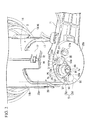
- FIG. 1 is a perspective view of a fuel supply device 1.
- the fuel supply device 1 is immersed in fuel in a fuel tank 2 of, for example, an automobile, a motorcycle, or the like and pumps up the fuel, thereby pumping the fuel to an internal-combustion engine (not shown).
- the fuel supply device 1 includes a fuel pump unit 30 and a suction filter 28 disposed on the suction side of the fuel pump unit 30.
- the suction side of the fuel pump unit 30 is set to be a lower side and the opposite side thereto is set to be an upper side.
- the fuel pump unit 30 includes a fuel pump 3 and a support section 4.
- the fuel pump 3 is composed of a pump section P disposed on the lower side and a motor section M mounted on the upper side of the pump section P.
- the pump section P for example, a non-displacement type regenerative pump having an impeller is used, and the pump is driven by the motor section M.
- the motor section M for example, a direct-current motor with brushes is used.
- a fuel suction section (a suction pipe) 7 is provided on the lower side of the pump section P and fuel is pumped up from the fuel suction section 7 into the fuel pump 3.
- a discharge port 8 is provided on the upper side of the motor section M. Fuel which has passed through the inside of the motor section M is pumped from the discharge port 8 to the outside of the fuel pump 3.
- the support section 4 is composed of a flange unit 9 fixed to an upper wall 2a among the inner wall surfaces of the fuel tank 2, an upper cup 10 which is provided on the lower side of the flange unit 9 and also covers the outside of the fuel pump 3, and a lower cup 20 which is mounted on the upper cup 10 and also covers the lower side of the fuel pump 3.
- an approximately circular plate-shaped unit main body 11 made of resin is provided at the flange unit 9.
- the unit main body 11 is fixed to the upper wall 2a in a state where it is inserted from the outside (the upper side) of the fuel tank 2 into an opening portion (not shown) formed in the upper wall 2a of the fuel tank 2. Therefore, the upper surface of the flange unit 9 is in a state of being exposed to the outside of the fuel tank 2.
- the discharge port 8 of the fuel pump 3 and a fuel extraction pipe 12 communicating with the discharge port 8 are provided at the flange unit 9, for example, a check valve or a pressure regulator is provided between a leading end of the fuel extraction pipe 12 and the discharge port 8, so that given fuel pressure can be secured.
- a connector (not shown) is provided on the upper surface of the flange unit 9.
- An external connector connected to an external power supply is fitted to the connector.
- the connector is made so as to be electrically connected to the motor section M of the fuel pump 3 and a sender gauge 23, whereby the motor section M is driven.
- a concave portion 13 is formed at the central area of the lower surface of the unit main body 11, and the upper cup 10 is formed integrally with the concave portion 13.
- a tubular cup main body 14 made of resin or the like is provided at the upper cup 10.
- the cup main body 14 is formed so as to cover the outer circumferential surface of the fuel pump 3 and formed so as to be able to insert the fuel pump 3 from an opening portion 14a formed in a lower end of the cup main body 14. Further, an outer circumferential surface 14b of the cup main body 14 extends from the flange unit 9 down to the approximate middle in an axial direction of the fuel pump 3.
- each engagement piece 17 extending toward the lower side in an axial direction of the opening portion 14a from a peripheral edge of the opening portion 14a are formed at equally-spaced intervals in the circumferential direction of the opening portion 14a.
- the engagement piece 17 is formed so as to be able to be elastically deformed toward the outside in the direction of an axis of the cup main body 14 and is caught in the lower cup 20 by the elastic force, thereby being mechanically held. Positioning in the direction of an axis and the circumferential direction of the lower cup 20 is performed by adjusting an engagement position of the engagement piece 17 with the lower cup 20.
- the engagement piece 17 extends to the lower side than the motor section M of the fuel pump 3. Further, an engagement hole 19 of the engagement piece 17 is engaged with an engagement protruding portion 18 which is formed at the lower cup 20 which is described below.
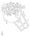
- FIG. 2 is a perspective view of the lower cup 20.
- the bottomed tube-shaped lower cup 20 formed of resin or the like is disposed on the lower side of the fuel pump 3, thereby supporting the fuel pump 3.
- the outer diameter of an outer circumferential surface 20a of the lower cup 20 is formed slightly smaller than the inner diameter of the outer circumferential surface 14b of the upper cup 10 (the cup main body 14).
- the engagement protruding portion 18 capable of being engaged with the engagement hole 19 of the engagement piece 17 is formed on the outer circumferential surface 20a of the lower cup 20, the engagement protruding portion 18 capable of being engaged with the engagement hole 19 of the engagement piece 17 is formed.
- the engagement protruding portion 18 is engaged with the engagement hole 19, whereby the lower cup 20 is held in the upper cup 10.
- the fuel pump 3 is supported by the integrated upper cup 10 and the lower cup 20.
- an end section (a bottom section) 20b is provided on the lower side of the lower cup 20.
- a support plate 21 extending to the outside in a radial direction of the lower cup 20 is formed integrally.
- a gauge mounting plate 22 is integrally formed so as to follow the direction of an axis of the lower cup 20, as shown in FIG. 1 .
- the sender gauge 23 is provided at the gauge mounting plate 22, the sender gauge 23 is provided.
- the sender gauge 23 is provided with a gauge main body 24 that is a liquid-level gauge which detects the remaining amount, that is, the liquid level position of fuel in the fuel tank 2 and is formed in a box shape, a rocking arm 34 which is provided so as to be able to be turned with respect to the gauge main body 24, and a float 35 which is provided at a leading end of the rocking arm 34 and can float on the liquid surface of fuel.
- a gauge main body 24 that is a liquid-level gauge which detects the remaining amount, that is, the liquid level position of fuel in the fuel tank 2 and is formed in a box shape
- a rocking arm 34 which is provided so as to be able to be turned with respect to the gauge main body 24, and a float 35 which is provided at a leading end of the rocking arm 34 and can float on the liquid surface of fuel.
- a degassing hole 27 is formed so as to pass through the end section 20b. Fuel vapor generated in the fuel pump 3 is discharged by the degassing hole 27. Further, a cover 27a which regulates a discharge direction of the fuel vapor that is discharged from the degassing hole 27 is integrally formed at the end section 20b so as to surround the degassing hole 27.
- a through-hole 26 is formed at a position corresponding to a suction pipe 7 of the fuel pump 3 so as to pass through the end section 20b.
- the diameter of the through-hole 26 is formed in the size of allowing the suction pipe 7 to be inserted therein.
- the suction pipe 7 is inserted into the through-hole 26 and also protrudes downward.
- An O-ring 25 is fitted to an opening end face 7b of a base of the portion of the suction pipe 7 protruding from the through-hole 26, so that sealing between the suction pipe 7 and a connection section (a connecting pipe) 38 (described later) is secured.
- a pair of second engagement sections 51 (described later) is provided in a protruding state at positions which are point-symmetrical with the through-hole 26 as the center.
- FIG. 3 is a perspective view of the suction filter 28.
- the suction filter 28 is provided with a filtering medium 36 and a welding section 37 formed at an outer peripheral edge of the filtering medium 36.
- the filtering medium 36 is a non-woven fabric formed in a bag shape and the welding section 37 is formed by welding the outer peripheral edges of the filtering medium 36 together.
- a connecting pipe 38 is provided to protrude upward.
- the connecting pipe 38 is coaxially connected to the suction pipe 7, thereby making the filtering medium 36 and the suction pipe 7 communicate with each other and also fixing the suction filter 28 to the lower cup 20.
- the connecting pipe 38 is formed of resin, and a lower opening of the connecting pipe 38 is covered by the filtering medium 36. In this way, the fuel in the fuel tank 2 flows into the connecting pipe 38 through the filtering medium 36. The fuel that flows into the connecting pipe 38 is pumped up to the fuel pump 3. Further, an upper opening of the connecting pipe 38 protrudes upward from the welding section 37.
- the inner diameter of the upper opening of the connecting pipe 38 is set to be a size in which the connecting pipe 38 can be externally fitted to the suction pipe 7.
- the inner circumferential surface of the projecting portion 38a is reduced in diameter from a middle position toward the lower side.
- a step provided at the boundary between a diameter-reduced area (a reduced diameter portion 41) and the upper side than the reduced diameter portion 41 of the inner circumferential surface of the projecting portion 38a is set to be a stepped surface 41a.
- the above-described O-ring 25 is disposed between the stepped surface 41a and the end section 20b of the lower cup 20.
- a pair of elastically deformable first engagement sections (engagement claws) 42 is provided on the slightly upper side than the middle in the direction of an axis 38d of the projecting portion 38a so as to become point-symmetrical with the axis 38d of the projecting portion 38a as the center.
- the engagement claw 42 is formed in an approximately quadrangular shape in vertical cross-section and in an approximate L-shape in transverse cross-section.
- the portion (a rising portion 43) on the base portion 42a side of the engagement claw 42 extends toward the direction of a tangent line (not shown) at the contact point 38c. Further, the engagement claw 42 is bent from the leading end side of the rising portion 43 and also extends along a circumferential direction.
- the portion further on the front side than the leading end side of the rising portion 43, of the engagement claw 42, is set to be a claw main body portion 44.
- a projection 45 which restricts falling-out from the second engagement section 51 (described later) is provided in a protruding state toward the projecting portion 38a side and so as to be approximately orthogonal to the claw main body portion 44.
- a first inclined surface 45b is formed which is orthogonal to the direction of rotation or is inclined toward the direction of rotation as it goes to the inside in a radial direction.
- a third inclined surface 45a is configured which is inclined toward the opposite direction of rotation as it goes to the inside in the radial direction. Further, the portion further on the leading end side than the projection 45 of the claw main body portion 44 forms an input portion 61 which accepts an external force when elastically deforming the claw main body portion 44.
- a groove 47 in which an upper end of the connecting pipe 38 can be fitted is formed so as to surround the through-hole 26.
- a small groove 48 in which the convex portion for preventing incorrect attachment 46 of the connecting pipe 38 can be fitted is formed in an approximate arc shape in a plan view.
- the size in a circumferential direction of the small groove 48 is set such that the convex portion for preventing incorrect attachment 46 can be turned around an axis 7a by a predetermined range.
- the connecting pipe 38 can be rotated around the axis 7a only by a predetermined range after the connecting pipe 38 is connected to the suction pipe 7.
- the small groove 48 is communicated with the portion on the middle side of the end section 20b, of an outer peripheral edge of the groove 47, and a step 48a is formed at the boundary line between the groove 47 and the small groove 48.
- the pair of second engagement sections 51 is provided in a protruding state so as to become point-symmetrical with the through-hole 26 as the center. Further, the respective second engagement sections 51 are formed so as to be able to be engaged with the pair of engagement claws 42.
- the second engagement section 51 is composed of a supporting portion 52 formed so as to protrude downward from the end section 20b, and a falling-out prevention wall 53 which is integrally formed at a leading end of the supporting portion 52 and extends toward the outside in a radial direction of the suction pipe 7.
- an acceptance concavity portion 54 capable of accepting each engagement claw 42 from a circumferential direction is configured on the base end side of each of the second engagement sections 51.
- a width W1 in the circumferential direction of the supporting portion 52 of the second engagement section 51 is set so as to become approximately equal to a distance L1 between the projection 45 and the rising portion 43.
- the leading end (the input portion) 61 of the claw main body portion 44 of the engagement claw 42 on at least one side among the pair of engagement claws 42 is in a state of protruding further to the outside in the radial direction than the outer circumferential surface 20a of the lower cup 20.
- the falling-out prevention wall 53 of the second engagement section 51 restricts the upward movement of the engagement claw 42, thereby restricting falling-out in a direction of the axis 38d of each engagement claw 42 inserted into the concavity portion 54.
- the falling-out prevention wall 53 is a flat plate-shaped wall formed in an approximate fan shape in a plan view as seen from above.
- the side surface on the side accepting the engagement claw 42, of the side surfaces of the falling-out prevention wall 53 forms a second inclined surface 53a which is orthogonal to the direction of rotation of the suction pipe 7 or is inclined at an inclination angle ⁇ toward the opposite side to the direction of rotation as it goes to the outside in the radial direction.
- a side surface opposite to the second inclined surface 53a is set to be a side surface 53b.
- An end on the outside in the radial direction of the suction pipe 7, of the second inclined surface 53a is set to be a corner portion 55, and an end on the inside in the radial direction is set to be an end portion 53e.
- the inclination angle ⁇ of the second inclined surface 53a is an angle which is made by intersection of a straight line connecting the axis 7a of the suction pipe 7 and the end portion 53e and the second inclined surface 53a.
- the inclination angle ⁇ is set so as to follow the first inclined surface 45b (refer to FIG. 4 ) of the projection 45 when the second inclined surface 53a and the projection 45 of the engagement claw 42 are present at positions overlapping in the direction of the axis 7a.
- An outer circumferential side surface 53d is provided to extend from the corner portion 55 to the side surface 53b.
- the side surface 53b is orthogonal to the direction of rotation of the suction pipe 7 and the outer circumferential side surface 53d is curved so as to bulge toward the outside in the radial direction of the suction pipe 7.
- a round chamfered portion 56 may also be formed at an area of the boundary line between the side surface 53b and the outer circumferential side surface 53d.
- an opening portion 57 described previously is formed at a position corresponding to a projection portion of the falling-out prevention wall 53.
- FIG. 2 is a diagram showing a schematic configuration of the lower cup 20
- FIG. 3 is a diagram showing a schematic configuration of the suction filter 28.
- FIGS. 4 to 6 show a state where the connecting pipe 38 of the suction filter 28 is mounted on the lower cup 20, wherein FIGS. 4 and 5 are explanatory diagrams showing a state where the connecting pipe 38 is normally attached and FIG. 6 is an explanatory diagram showing a state where the connecting pipe 38 is wrongly attached.
- the fuel pump 3 is inserted into the cup main body 14 (the upper cup 10). If the fuel pump 3 is inserted into the cup main body 14 (the upper cup 10), the lower cup 20 is inserted into the cup main body 14 (the upper cup 10). Then, if the lower cup 20 is inserted into the cup main body 14 (the upper cup 10), the engagement protruding portion 18 of the lower cup 20 and the engagement piece 17 of the upper cup 20 are engaged with each other, so that the lower cup 20 is held on the cup main body 14.
- the connecting pipe 38 is externally fitted to the suction pipe 7 in a state where the axis 38d of the connecting pipe 38 of the suction filter 28 conforms to the axis 7a of the suction pipe 7.
- the position of each of the engagement claws 42 of the connecting pipe 38 is adjusted so as to become a position which does not interfere with each of the second engagement sections 51 which are provided in a protruding state at the lower cup 20.
- the convex portion for preventing incorrect attachment 46 of the connecting pipe 38 is adjusted so as to be at a position corresponding to the groove portion (the small groove) 48 of the lower cup 20. As shown in FIG.
- the size in the circumferential direction of the small groove 48 is set so as to permit the turning around of the axis 7a of the convex portion for preventing incorrect attachment 46 only by a predetermined range. If the suction pipe 7 is inserted into the connecting pipe 38 in this state, the convex portion for preventing incorrect attachment 46 of the connecting pipe 38 is fitted into the small groove 48 and also comes into contact with the step 48a of the boundary line between the groove 47 and the small groove 48. Then, the O-ring 25 is compressed toward the direction of the axis 38d between the stepped surface 41a shown in FIG. 3 and the opening end face 7b of the suction pipe 7. In this way, the clearance between the inner circumferential surface of the connecting pipe 38 and the outer circumferential surface of the suction pipe 7 is sealed by the O-ring 25.
- the connecting pipe 38 is rotated around the axis 7a of the suction pipe 7 in the counter-clockwise direction in a state where the suction pipe 7 is inserted into the connecting pipe 38.
- a counter-clockwise rotation direction is shown as an arrow CCW.
- the third inclined surface 45a of the projection 45 comes into contact with the supporting portion 52 of the second engagement section 51. If the connecting pipe 38 is further rotated around the axis 7a from here, a force in a radial direction acts radially outward at the third inclined surface 45a. As a result, the engagement claw 42 is pushed and spread radially outward and at the same time, the projection 45 is placed on the radially outer side surface of the supporting portion 52.
- the connecting pipe 38 is further rotated around the axis 7a, the radially inner side surface of the engagement claw 42 passes the radially outer side surface of the supporting portion 52. At that time, a radially inward restoring force acts on the engagement claw 42, so that both ends in the circumferential direction of the supporting portion 52 are pinched by the projection 45 of the engagement claw 42 and the radially inner side surface of the rising portion 43 (refer to FIG. 5 ). At this time, the movement of the engagement claw 42 in a direction of falling out from the second engagement section 51 is restricted by the projection 45. As a result, the rotation around the axis 7a of the connecting pipe 38 is restricted.
- the connecting pipe 38 is externally fitted and fixed to the suction pipe 7, so that mounting of the suction filter 28 on the lower cup 20 is completed.
- the claw main body portion 44 is elastically deformed radially outward by inputting an external force to each of the input portions 61 of the pair of engagement claws 42.
- the claw main body portion 44 is elastically deformed radially outward by inputting an external force to each of the input portions 61 of the pair of engagement claws 42.
- the connecting pipe 38 is rotated around the axis 7a in the direction of the arrow CCW in a state where a gap is present between the end section 20b and the outer peripheral edge 38e that is a leading end of the connecting pipe 38 in this manner, the first inclined surface 45b of the projection 44 comes into contact with the second inclined surface 53a of the falling-out prevention wall 53.
- the projection 45 of the engagement claw 42 is provided in a protruding state so as to be approximately orthogonal to the claw main body portion 45 and also the first inclined surface 45b is orthogonal to the direction of rotation or is inclined toward the direction of rotation as it goes to the inside in the radial direction.
- the second inclined surface 53a of the falling-out prevention wall 53 is orthogonal to the direction of rotation of the suction pipe 7 or is inclined at the inclination angle ⁇ toward the opposite side to the direction of rotation as it goes to the outside in the radial direction. Further, the inclination angle ⁇ is set so as to follow the first inclined surface 45b of the projection 45 when the second inclined surface 53a and the projection 45 of the engagement claw 42 are present at positions overlapping in the direction of the axis 7a.
- the round chamfered portion 56 is formed at an area of the boundary line between the second inclined surface 53a and an outer circumferential side surface 53c, there is a case where at the time of preventing incorrect attachment of the suction filter 28, the round chamfered portion 56 and the projection 45 of the engagement claw 42 come into contact with each other, so that a radially outward force acts on the engagement claw 42. For this reason there is a concern that the projection 45 may be placed on the falling-out prevention wall 53.
- the corner portion 55 which is formed at the second inclined surface 53a of the falling-out prevention wall 53 functions as a fail-safe for reliably preventing the incorrect attachment of the suction filter 28 and preventing dropping-out of the suction filter 28 from the lower cup 20.
- connection section (the connecting pipe) 38 of the suction filter 28 is coaxially connected to the fuel suction section (the suction pipe) 7 provided at the fuel pump unit 30, the connecting pipe 38 is rotated around the axis 7a thereof, the suction pipe 7 and the connecting pipe 38 cooperate with each other, so that the connection state is maintained. For this reason, there is no need to separately prepare a member such as a metal bracket for fixing the suction filter 28 in attaching the connecting pipe 38 of the suction filter 28 to the suction pipe 7, so that it is possible to reduce the number of components.
- suction filter 28 is directly attached to the suction pipe 7, it is possible to easily perform the attaching and dismounting work of the suction filter 28 without using a jig. Accordingly, it is possible to improve the workability of attaching the connecting pipe 38 to the suction pipe 7.
- the first engagement section (the engagement claw) 42 is provided at the connecting pipe 38 of the suction filter 28, whereby it is possible to replace the suction filter 28 and the connecting pipe 38 at the same time. For this reason, for example, compared to a case where the engagement claw 42 is provided at the lower cup 20, it becomes possible to easily perform the replacement work of the engagement claw 42.
- the engagement claw 42 is composed of the rising portion 43 extending toward the direction of a tangent line (not shown) at the contact point 38c, and the claw main body portion 44 which is bent from the leading end side of the claw main body portion 44 of the rising portion 43 and also extends along the circumferential direction.
- the engagement claw 42 and the second engagement section 51 can be easily engaged with each other by rotating the connecting pipe 38 around the axis 7a.
- the claw main body portion 44 unlike a structure in which the engagement claw 42 and the second engagement section 51 are engaged with each other simultaneously with inserting the connecting pipe 38 into the suction pipe 7, it is acceptable if the claw main body portion 44 extends in the circumferential direction, and the claw main body portion 44 need not be extended along the direction of the axis 38d.
- the engagement claw 42 even if the engagement claw 42 is formed at a length required to engage with the second engagement section 51, the engagement claw 42 does not protrude in the direction of the axis 38d. For this reason, it is possible to reduce the length in the direction of the axis 38d of the connecting pipe 38 (the projecting portion 38a), so that it becomes possible to attain a reduction in the size of the fuel supply device 1. Further, since it is possible to make the fixing mechanisms composed of the engagement claw 42 and the second engagement section 51 be a simple structure, it is possible to reduce the manufacturing cost of the fuel supply device 1.
- the engagement claw 42 is provided with the projection 45 which restricts falling-out from the second engagement section, whereby it is possible to reliably maintain the engagement state of the engagement claw 42 and the second engagement section 51. For this reason, dropping-out of the suction pipe 7 from the connecting pipe 38 can be reliably prevented. That is, it is possible to prevent dropping-out of the suction filter 28 from the lower cup 20.
- the portion further on the leading end side than the projection 45 of the engagement claw 42 forms the input portion 61 which accepts an external force when the engagement claw 42 is elastically deformed radially outward.
- the input portion 61 acts as a power point of elastically deforming the engagement claw 42 and is located at a position farther from a supporting point (the base portion 42a) than the projection 45 that is a point of action.
- the input portion 61 of the engagement claw 42 on at least one side among the pair of engagement claws 42 protrudes further from the outside in the radial direction than the outer circumferential surface of the fuel pump unit 30 (the outer circumferential surface 20a of the lower cup 20) in a state where the connecting pipe 38 is connected to the suction pipe 7, when applying an external force to each of the input portions 61, it is possible to easily apply an external force to a protruding portion of the input portion 61. For this reason, it is possible to easily attach the suction filter 28 and to improve the dismounting performance of the suction filter 28.
- the convex portion for preventing incorrect attachment 46 is formed at the outer peripheral edge 38e that is a leading end of the connecting pipe 38 (the projecting portion 38a) and also the small groove 48 in which the convex portion for preventing incorrect attachment 46 can be fitted is formed in the end section 20b of the lower cup 20. Further, a structure is made in which in a case where the connecting pipe 38 is not mounted on the suction pipe 7 in a given direction, the connecting pipe 38 is not inserted up to a given depth.
- the engagement claw 42 is not fitted until it is located at a position where it can be completely connected to the second engagement section 51 of the suction pipe 7, and a gap is formed between the end section 20b and the outer peripheral edge 38e that is a leading end of the connecting pipe 38. Accordingly, incorrect attachment of the suction filter 28 can be prevented.
- the side surface on the front side in the direction of rotation of the projection 45 of the engagement claw 42 forms the first inclined surface 45b which is orthogonal to the direction of rotation or is inclined toward the direction of rotation as it goes to the inside in the radial direction
- the side surface on the side accepting the engagement claw 42 of the falling-out prevention wall forms the second inclined surface 53a which is orthogonal to the direction of rotation or is inclined toward the opposite side to the direction of rotation as it goes to the outside in the radial direction.
- FIG. 7 is a perspective view of a connecting pipe 138 in this embodiment
- FIG. 8 is a perspective view of a lower cup 120 in this embodiment.
- a description is made with the same reference numeral added thereto.
- the fuel supply device 1 in the second embodiment is the same as that in the above-described first embodiment in that:
- a pair of elastically deformable engagement claws 142 is provided at positions which are point-symmetrical with an axis 138d of the projecting portion 138a as the center. Further, the engagement claw 142 is formed in an approximate L-shape in a transverse cross-section.
- the portion (a rising portion 143) on the base portion 142a side of the engagement claw 142 extends toward the direction of a tangent line (not shown) at the contact point 138c.
- the engagement claw 142 is bent from the leading end side of the rising portion 142 and also extends along a circumferential direction.
- the portion further on the front side than the leading end side of the rising portion 143 of the engagement claw 142 is set to be a claw main body portion 144.
- an opening portion 146 is formed in the central area in a plan view of the claw main body portion 144.
- a pair of second engagement sections 151 is respectively provided in a protruding state at places corresponding to the pair of engagement claws 142.
- the second engagement section 151 is composed of a supporting wall 152 capable of being interposed between the connecting pipe 138 and the claw main body portion 144 and having an arc shape in a cross-section, and an engagement protruding portion 153.
- the engagement protruding portion 153 is provided in a protruding state at a site corresponding to the opening portion 146, of the radially outer surface of the supporting wall 152.
- the engagement protruding portion 153 is formed so as to be capable of being fitted into the opening portion 146 of the claw main body portion 144.
- the attaching procedure of the fuel supply device 1 is the same as that in the first embodiment described previously.
- the connecting pipe 138 is externally fitted to the suction pipe 7 in a state where the axis 138d of an upper opening of the connecting pipe 138 of the suction filter 128 conforms to the axis 7a of the suction pipe 7.
- the position of each of the engagement claws 142 of the connecting pipe 138 is adjusted so as to become a position which does not interfere with each second engagement section 151 which is provided in a protruding state at the lower cup 120.
- the position of the convex portion for preventing incorrect attachment 46 of the connecting pipe 138 is adjusted so as to become a position corresponding to the groove portion (the small groove 48) of the lower cup 120.
- the connecting pipe 138 is rotated around the axis 7a in the counter-clockwise direction (refer to the arrow CCW in FIG. 7 ). Then, the supporting wall 152 of the lower cup 120 is interposed in a gap 150 between the connecting pipe 138 and the claw main body portion 144. Then, a leading end 144a of the claw main body portion 144 comes into contact with the engagement protruding portion 153 of the supporting wall 152.
- the connecting pipe 138 is further rotated around the axis 7a, a force in a radial direction acts radially outward at the leading end 144a. As a result, the claw main body portion 144 is pushed and spread radially outward, so that the claw main body portion 144 is placed on the radially outer side surface of the engagement protruding portion 153. If the connecting pipe 138 is further rotated around the axis 7a, when the position of the engagement protruding portion 153 and the position of the opening portion 146 conform to each other, a radially inward restoring force acts on the engagement claw 142, so that the engagement protruding portion 153 is engaged with the opening portion 146. In this way, the engagement claw 142 is held on the second engagement section 151.
- the connecting pipe 138 is externally fitted and fixed to the suction pipe 7, so that mounting of the suction filter 28 on the lower cup 120 is completed.
- the engagement claw 142 is elastically deformed radially outward by inputting an external force to a leading end (an input portion 161) of the claw main body portion 144 of each of the engagement claws 142. Then, each opening portion 146 is separated from each engagement protruding portion 153, so that the engagement state of each of the second engagement sections 151 and each of the engagement claws 142 is released. In this state, the connecting pipe 138 is rotated around the axis 7a in the clockwise direction (refer to the arrow CW in FIG. 7 ). In this way, each engagement claw 142 is pulled out of each gap 150, so that the suction filter 28 can be dismounted from the lower cup 120.
- the engagement claw 142 can be formed larger than the engagement claw 42 in the first embodiment described previously. For this reason, it becomes possible to increase the rigidity of the engagement claw 142. Further, since it is possible to make the contact area between the engagement claw 142 and the second engagement section 151 large compared to the first embodiment, it becomes possible to increase the holding force of the connecting pipe 138 by the engagement claw 142. Further, since it is possible to make the structures of the engagement claw 142 and the second engagement section 151 simple, the manufacturing cost of the fuel supply device 1 can be reduced.
- the invention is not limited only to the configuration of each embodiment described above and includes configurations in which various changes are added to each embodiment described above within a scope that does not depart from the purpose of the invention.
- a description has been made with regard to a case where the connecting pipe 38 (138) of the suction filter 28 is externally fitted and fixed to the suction pipe 7 which protrudes from the end section 20b (120b) of the lower cup 20 (120).
- a fixing method of the connecting pipe 38 (138) to the suction pipe 7 is not limited only thereto and each configuration may also be changed such that the connecting pipe 38 (138) is internally fitted and fixed to the suction pipe 7.
- the connecting pipe 38 (138) is internally fitted and fixed to the suction pipe 7, it is acceptable if fixing mechanisms which replace the engagement claw 42 (142) provided in a protruding state at the connecting pipe 38 (138) or the second engagement section 51 (151) provided in a protruding state at the lower cup 20 (120) is provided.
- fixing mechanisms which replace the engagement claw 42 (142) provided in a protruding state at the connecting pipe 38 (138) or the second engagement section 51 (151) provided in a protruding state at the lower cup 20 (120) is provided.
- a configuration is also acceptable in which a groove being long in the circumferential direction is formed in the outer circumferential surface of the suction pipe 7 and a projection capable of being fitted into the groove of the suction pipe 7 is formed at the connecting pipe 38 or 138.
- Such fixing mechanisms are not limited to the above-described mechanisms, and provided that if the connecting pipe 38 (138) is rotated around an axis after the connecting pipe 38 (138) is externally fitted to the suction pipe 7, the suction pipe 7 and the connecting pipe 38 (138) are engaged with each other, any structure can be employed.
- the convex portion for preventing incorrect attachment 46 is provided at the leading end of the connecting pipe 38 (138) and the small groove 48 in which the convex portion for preventing incorrect attachment 46 can be fitted is formed in the end section 20b (120b) of the lower cup 20 (120).
- the configuration of engaging the connecting pipe 38 (138) with the suction pipe 7 is not limited thereto and a configuration is also acceptable in which the convex portion for preventing incorrect attachment 46 is formed at the end section 20b (120b) of the lower cup 20 (120) and a groove in which the convex portion for preventing incorrect attachment 46 can be fitted is formed in the leading end of the connecting pipe 38 (138).
- the wall thickness in a radial direction of the connecting pipe 38 (138) is set to be a thickness allowing a groove to be formed therein.
- the numbers of engagement claws 42 (142) and second engagement sections 51 (151) are not limited thereto and it is acceptable if at least one engagement claw 42 (142) is provided in a protruding state at the connecting pipe 38 (138) and at least one second engagement section 51 (151) is provided in a protruding state at the lower cup 20 (120).
Abstract
Description
- The present invention relates to a fuel supply device.
Priority is claimed on Japanese Patent Application No.2010-023478 filed on February 4, 2010 - In general, as a fuel supply device for a vehicle such as a motorcycle or a four-wheel vehicle, in many cases, a so-called in-tank type is adopted in which a fuel pump is disposed in a fuel tank and a fuel supply device is immersed in fuel in the fuel tank. In the fuel pump of this type of fuel supply device, a pump section which pumps up fuel, thereby pumping the fuel to an internal-combustion engine (an engine), is provided on the bottom surface side of the fuel tank. Further, at the top of the pump section, a motor section which drives the pump section is provided, and a suction filter (a filter) is attached to the bottom of the pump section through a fuel suction port (a fuel suction section).
The suction filter filters fuel which is pumped up by the pump section, thereby preventing foreign matters in the fuel tank from entering to the pump section. - As a method of attaching the suction filter to the fuel suction section, a technique is disclosed in which a pipe which can be connected to the fuel suction section is provided, and a projection provided at the fuel suction section in the vicinity of a suction port of the pump section is fixed to a flange section integrally provided on the outer circumferential surface of the pipe through a metal bracket (refer to Patent Document 1, for example).
In the metal bracket, an engagement hole in which the projection can be inserted is provided. At a peripheral edge of the engagement hole, a plurality of claws is formed. These claws play a role as retainers preventing the projection falling-out when the projection is inserted into the engagement hole. Further, in the flange section, a mounting hole is formed at a site corresponding to the engagement hole. Then, the metal bracket is swaged and fixed to the flange section by using a jig in a state where the mounting hole of the flange section and the engagement hole of the metal bracket overlap each other.
In this manner, it is attempted to improve the attachment workability of the suction filter by fixing the projection of the pump section through the metal bracket. -
- [Patent Document 1] Japanese Unexamined Patent Application, First Publication No.
2006-9611 - However, in the fuel supply device in the related art described above, since there is a need to separately prepare the metal bracket in order to attach the suction filter to the fuel suction section, an increase in the number of components becomes a problem.
Further, since the metal bracket is swaged and fixed to the flange section of the suction filter by using a jig, the attaching work and the dismounting work of the suction filter become complicated. For this reason, there is a problem in that it is difficult to improve the workability of attaching the suction filter to the fuel suction section. - The present invention has been made in view of the above-described problems and has an object to provide a fuel supply device which allows the work of attaching and dismounting a suction filter to be easily performed without increasing the number of components.
- The present invention adopts the following configurations in order to solve the above problems, thereby achieving a relevant object.
- [1] According to an aspect of the invention, there is provided a fuel supply device including: a fuel pump unit having a fuel pump which is disposed in a fuel tank and pumps up fuel in the fuel tank, thereby pumping the fuel to an internal-combustion engine, and a support section which fixes the fuel pump to an inner wall surface of the fuel tank; and a suction filter which is mounted on a fuel suction section provided at the fuel pump unit and filters the fuel that is suctioned into the fuel pump, wherein the suction filter has a connection section which protrudes toward the fuel pump unit and is also coaxially connected to the fuel suction section, and at both the fuel pump unit and the connection section, fixing mechanisms are provided which maintain the connection state of the connection section in cooperation with each other in a case where the connection section has been rotated around an axis thereof in a state where the connection section has been connected to the suction section.
- [2] In the fuel supply device according to the above [1], each of the fuel suction section and the connection section may have a tubular shape and also the connection section may be connected to the fuel suction section, and the fixing mechanisms may include a first engagement section provided on the outer circumferential surface of the connection section, and a second engagement section which is formed at the fuel pump unit and accepts the first engagement section from a circumferential direction, thereby being engaged with the first engagement section.
- [3] In the fuel supply device according to above [2], the first engagement section may extend in a circumferential direction of the connection section, be elastically deformable, and be provided with a projection which restricts falling-out from the second engagement section.
- [4] In the fuel supply device according to above [3], the projection may be disposed at a middle position in a longitudinal direction of the first engagement section, and a portion further on the leading end side than the projection of the first engagement section may form an input portion which accepts an external force when elastically deforming the first engagement section.
- [5] In the fuel supply device according to above [4], at least one of the input portions may protrude further to the outside in a radial direction than the outer circumferential surface of the fuel pump unit in a state where the connection section has been connected to the fuel suction section.
- [6] The fuel supply device according to any one of the above [1] to [5] may further include: a convex portion for preventing incorrect attachment provided at one of an outer peripheral edge on the fuel pump unit side of the connection section and the fuel pump unit; and a groove portion which is provided at other one of the outer peripheral edge on the fuel pump unit side of the connection section and the fuel pump unit, and in which the convex portion for preventing incorrect attachment can be fitted, wherein the size in a circumferential direction of the groove portion may be set so as to permit the turning around the axis of the convex portion for preventing incorrect attachment only by a predetermined range.
- [7] In the fuel supply device according to the above [3], the first engagement section may be provided in a pair at positions which are point-symmetrical with an axis of the connection section as the center, and also the projection may be provided in a protruding state on the radially inner surface side of each of the first engagement sections, the surface on the front side in a direction of rotation of each of the projections may form a first inclined surface which is orthogonal to the direction of rotation or is inclined toward the direction of rotation as it goes to the inside in a radial direction, the second engagement section may be provided in a pair at the fuel pump unit, a concave portion which accepts each of the first engagement sections may be formed on the base end side of each of the second engagement sections, while a falling-out prevention wall which restricts the falling-out in an axial direction of each of the first engagement sections inserted into the concave portion may be formed on the leading end side of each of the second engagement sections, and the side surface on the side accepting each first engagement section, of each of the falling-out prevention walls, may form a second inclined surface which is orthogonal to the direction of rotation or is inclined toward the opposite side to the direction of rotation as it goes to the outside in the radial direction.
- According to the fuel supply device related to the aspect of the above [1], if in a state where the connection section of the suction filter is coaxially connected to the fuel suction section provided at the fuel pump unit, the connection section is rotated around the axis thereof, the fuel suction section and the connection section cooperate with each other, whereby the connection state of the connection section is maintained. For this reason, there is no need to separately prepare a member such as a metal bracket for fixing the suction filter in attaching the connection section of the suction filter to a fuel suction port, so that it is possible to reduce the number of components. Further, since the suction filter is directly attached to the fuel suction port, it is possible to easily perform the attaching and dismounting work of the suction filter without using a jig. Accordingly, it is possible to improve the workability of attaching the suction filter to the fuel suction port.
- Further, according to the fuel supply device related to the above [2], the first engagement section can be easily engaged with the second engagement section by rotating the connection section around the axis in a state where the connection section is connected to the fuel suction section. Further, since it is possible to make the fixing mechanisms be a simple structure, the manufacturing cost of the fuel supply device can be reduced.
- Further, according to the fuel supply device related to the above [3], since the first engagement section extends in the circumferential direction of the tubular connection section, even if the first engagement section is formed at a length required to engage with the second engagement section, the first engagement section does not protrude in the direction of the axis. For this reason, it is possible to reduce the length of the connection section in the axis direction thereof.
Further, the first engagement section is provided with the projection which restricts falling-out from the second engagement section, whereby dropping-out of the fuel suction section from the connection section can be reliably prevented. - Further, according to the fuel supply device related to the above [4], the portion further on the leading end side than the projection of the first engagement section forms the input portion which accepts an external force when elastically deforming the first engagement section. Due to this configuration, the input portion acts as a power point for elastically deforming the first engagement section and is located at a position farther from a supporting point than the projection that is a point of action. For this reason, it is possible to separate the projection from the second engagement section by elastically deforming the first engagement section by applying to the input portion a smaller external force than the case of directly applying an external force with the projection as a power point. In this way, it is possible to easily release the engagement state of the first engagement section and the second engagement section. Accordingly, it is possible to improve the dismounting performance of the suction filter.
- Further, according to the fuel supply device related to the above [5], since at least one of the input portions protrudes further from the outside in a radial direction than the outer circumferential surface of the fuel pump unit in a state where the connection section has been connected to the fuel suction section, it is easier to apply an external force to the input portion. For this reason, it is possible to more easily attach the suction filter and to improve the dismounting performance.
- Further, according to the fuel supply device related to the above [6], the size in a circumferential direction of the groove portion is set so as to permit the turning around the axis of the convex portion for preventing incorrect attachment only by a predetermined range. For this reason, in a case where the connection section is not mounted on the fuel suction section in a given direction, the convex portion for preventing incorrect attachment is not fitted into the groove portion. As a result, at the time of attaching the suction filter, since the first engagement section of the connection section is not externally fitted to the second engagement section of the fuel suction section until the first engagement section is located at a completely connectable position, it is possible to prevent incorrect attachment of the suction filter.
- Further, according to the fuel supply device related to the above [7], in a case where the connection section is wrongly attached to the fuel suction section, even if the surface on the front side in a direction of rotation of the projection comes into contact with the falling-out prevention wall of the second engagement section, a radially outward force does not act on the first engagement section.
That is, the surface on the front side in a direction of rotation of the projection of the first engagement section forms the first inclined surface which is orthogonal to the direction of rotation or is inclined toward the direction of rotation as it goes to the inside in the radial direction, while the side surface on the side accepting the first engagement section, of the falling-out prevention wall, forms the second inclined surface which is orthogonal to the direction of rotation or is inclined toward the opposite side to the direction of rotation as it goes to the outside in the radial direction. For this reason, even if the first inclined surface and the second inclined surface come into contact with each other, so that a force in a radial direction acts on the second inclined surface from the first inclined surface, the force acts radially or inward radially at the second inclined surface. As a result, the radially outward elastic deformation of the first engagement section is prevented.
By the above, the projection of the first engagement section can be prevented from being placed on the leading end of the second engagement section, so that it becomes possible to reliably prevent incorrect attachment of the connection section. -
-
FIG. 1 is a perspective view showing a schematic configuration of a fuel supply device in a first embodiment of the invention. -
FIG. 2 is a perspective view showing a schematic configuration of a lower cup in the embodiment. -
FIG. 3 is a perspective view showing a schematic configuration of a suction filter in the embodiment. -
FIG. 4 is an explanatory diagram showing a state where the suction filter is mounted on the lower cup in the embodiment. -
FIG. 5 is an explanatory diagram showing a state where the suction filter is mounted on the lower cup in the embodiment. -
FIG. 6 is an explanatory diagram showing a state where the suction filter is wrongly attached to the lower cup in the embodiment. -
FIG. 7 is a perspective view showing a schematic configuration of a connecting pipe in a second embodiment of the invention. -
FIG. 8 is a perspective view showing a schematic configuration of a support section in the embodiment. - Hereinafter, a first embodiment of a fuel supply device according to the invention will be described with reference to the drawings. In addition, in the following drawings, in order to show each member at a recognizable size, the scale of each member is appropriately changed.
-
FIG. 1 is a perspective view of a fuel supply device 1.
As shown in the drawing, the fuel supply device 1 is immersed in fuel in afuel tank 2 of, for example, an automobile, a motorcycle, or the like and pumps up the fuel, thereby pumping the fuel to an internal-combustion engine (not shown).
The fuel supply device 1 includes afuel pump unit 30 and asuction filter 28 disposed on the suction side of thefuel pump unit 30. In addition, in the following description, the suction side of thefuel pump unit 30 is set to be a lower side and the opposite side thereto is set to be an upper side. - The
fuel pump unit 30 includes afuel pump 3 and asupport section 4. Thefuel pump 3 is composed of a pump section P disposed on the lower side and a motor section M mounted on the upper side of the pump section P. As the pump section P, for example, a non-displacement type regenerative pump having an impeller is used, and the pump is driven by the motor section M. As the motor section M, for example, a direct-current motor with brushes is used.
A fuel suction section (a suction pipe) 7 is provided on the lower side of the pump section P and fuel is pumped up from thefuel suction section 7 into thefuel pump 3. Further, adischarge port 8 is provided on the upper side of the motor section M. Fuel which has passed through the inside of the motor section M is pumped from thedischarge port 8 to the outside of thefuel pump 3. - The
support section 4 is composed of aflange unit 9 fixed to anupper wall 2a among the inner wall surfaces of thefuel tank 2, anupper cup 10 which is provided on the lower side of theflange unit 9 and also covers the outside of thefuel pump 3, and alower cup 20 which is mounted on theupper cup 10 and also covers the lower side of thefuel pump 3. - At the
flange unit 9, an approximately circular plate-shaped unitmain body 11 made of resin is provided. The unitmain body 11 is fixed to theupper wall 2a in a state where it is inserted from the outside (the upper side) of thefuel tank 2 into an opening portion (not shown) formed in theupper wall 2a of thefuel tank 2. Therefore, the upper surface of theflange unit 9 is in a state of being exposed to the outside of thefuel tank 2.
Further, at theflange unit 9, thedischarge port 8 of thefuel pump 3 and afuel extraction pipe 12 communicating with thedischarge port 8 are provided. That is, the fuel in thefuel tank 2 is pumped from thedischarge port 8 through thefuel extraction pipe 12 to the internal-combustion engine.
In addition, at theflange unit 9, for example, a check valve or a pressure regulator is provided between a leading end of thefuel extraction pipe 12 and thedischarge port 8, so that given fuel pressure can be secured. - Further, on the upper surface of the
flange unit 9, a connector (not shown) is provided. An external connector connected to an external power supply is fitted to the connector. The connector is made so as to be electrically connected to the motor section M of thefuel pump 3 and asender gauge 23, whereby the motor section M is driven.
Further, aconcave portion 13 is formed at the central area of the lower surface of the unitmain body 11, and theupper cup 10 is formed integrally with theconcave portion 13. - At the
upper cup 10, a tubular cupmain body 14 made of resin or the like is provided. The cupmain body 14 is formed so as to cover the outer circumferential surface of thefuel pump 3 and formed so as to be able to insert thefuel pump 3 from anopening portion 14a formed in a lower end of the cupmain body 14. Further, an outercircumferential surface 14b of the cupmain body 14 extends from theflange unit 9 down to the approximate middle in an axial direction of thefuel pump 3. - Further, at the cup
main body 14, fourengagement pieces 17 extending toward the lower side in an axial direction of theopening portion 14a from a peripheral edge of theopening portion 14a are formed at equally-spaced intervals in the circumferential direction of theopening portion 14a. Theengagement piece 17 is formed so as to be able to be elastically deformed toward the outside in the direction of an axis of the cupmain body 14 and is caught in thelower cup 20 by the elastic force, thereby being mechanically held. Positioning in the direction of an axis and the circumferential direction of thelower cup 20 is performed by adjusting an engagement position of theengagement piece 17 with thelower cup 20.
Theengagement piece 17 extends to the lower side than the motor section M of thefuel pump 3. Further, anengagement hole 19 of theengagement piece 17 is engaged with anengagement protruding portion 18 which is formed at thelower cup 20 which is described below. -
FIG. 2 is a perspective view of thelower cup 20.
As shown inFIGS. 1 and2 , the bottomed tube-shapedlower cup 20 formed of resin or the like is disposed on the lower side of thefuel pump 3, thereby supporting thefuel pump 3. The outer diameter of an outercircumferential surface 20a of thelower cup 20 is formed slightly smaller than the inner diameter of the outercircumferential surface 14b of the upper cup 10 (the cup main body 14).
On the outercircumferential surface 20a of thelower cup 20, theengagement protruding portion 18 capable of being engaged with theengagement hole 19 of theengagement piece 17 is formed. Theengagement protruding portion 18 is engaged with theengagement hole 19, whereby thelower cup 20 is held in theupper cup 10. Then, thefuel pump 3 is supported by the integratedupper cup 10 and thelower cup 20. - Further, an end section (a bottom section) 20b is provided on the lower side of the
lower cup 20. At theend section 20b, asupport plate 21 extending to the outside in a radial direction of thelower cup 20 is formed integrally. At a leading end of thesupport plate 21, agauge mounting plate 22 is integrally formed so as to follow the direction of an axis of thelower cup 20, as shown inFIG. 1 . At thegauge mounting plate 22, thesender gauge 23 is provided. Thesender gauge 23 is provided with a gaugemain body 24 that is a liquid-level gauge which detects the remaining amount, that is, the liquid level position of fuel in thefuel tank 2 and is formed in a box shape, a rockingarm 34 which is provided so as to be able to be turned with respect to the gaugemain body 24, and afloat 35 which is provided at a leading end of the rockingarm 34 and can float on the liquid surface of fuel. - Further, at a position further on the
support plate 21 side than the central portion of theend section 20b, adegassing hole 27 is formed so as to pass through theend section 20b. Fuel vapor generated in thefuel pump 3 is discharged by thedegassing hole 27. Further, acover 27a which regulates a discharge direction of the fuel vapor that is discharged from thedegassing hole 27 is integrally formed at theend section 20b so as to surround thedegassing hole 27. - Further, in the
end section 20b, a through-hole 26 is formed at a position corresponding to asuction pipe 7 of thefuel pump 3 so as to pass through theend section 20b. The diameter of the through-hole 26 is formed in the size of allowing thesuction pipe 7 to be inserted therein. Thesuction pipe 7 is inserted into the through-hole 26 and also protrudes downward. An O-ring 25 is fitted to an openingend face 7b of a base of the portion of thesuction pipe 7 protruding from the through-hole 26, so that sealing between thesuction pipe 7 and a connection section (a connecting pipe) 38 (described later) is secured.
Further, at theend section 20b, a pair of second engagement sections 51 (described later) is provided in a protruding state at positions which are point-symmetrical with the through-hole 26 as the center. -
FIG. 3 is a perspective view of thesuction filter 28.
As shown inFIGS. 1 and3 , thesuction filter 28 is provided with afiltering medium 36 and awelding section 37 formed at an outer peripheral edge of thefiltering medium 36. Thefiltering medium 36 is a non-woven fabric formed in a bag shape and thewelding section 37 is formed by welding the outer peripheral edges of thefiltering medium 36 together. - At the place corresponding to the
suction pipe 7 of thefuel pump 3, of thesuction filter 28, a connectingpipe 38 is provided to protrude upward. The connectingpipe 38 is coaxially connected to thesuction pipe 7, thereby making thefiltering medium 36 and thesuction pipe 7 communicate with each other and also fixing thesuction filter 28 to thelower cup 20.
The connectingpipe 38 is formed of resin, and a lower opening of the connectingpipe 38 is covered by thefiltering medium 36. In this way, the fuel in thefuel tank 2 flows into the connectingpipe 38 through thefiltering medium 36. The fuel that flows into the connectingpipe 38 is pumped up to thefuel pump 3.
Further, an upper opening of the connectingpipe 38 protrudes upward from thewelding section 37. The portion protruding from thewelding section 37, of the connectingpipe 38, becomes a projectingportion 38a. Then, at an outerperipheral edge 38e of the upper side (a leading end) of the projectingportion 38a, a convex portion for preventingincorrect attachment 46 is formed at one place. - The inner diameter of the upper opening of the connecting
pipe 38 is set to be a size in which the connectingpipe 38 can be externally fitted to thesuction pipe 7. The inner circumferential surface of the projectingportion 38a is reduced in diameter from a middle position toward the lower side. A step provided at the boundary between a diameter-reduced area (a reduced diameter portion 41) and the upper side than the reduced diameter portion 41 of the inner circumferential surface of the projectingportion 38a is set to be a steppedsurface 41a. The above-described O-ring 25 is disposed between the steppedsurface 41a and theend section 20b of thelower cup 20. - On an outer
circumferential surface 38b of the projectingportion 38a, a pair of elastically deformable first engagement sections (engagement claws) 42 is provided on the slightly upper side than the middle in the direction of anaxis 38d of the projectingportion 38a so as to become point-symmetrical with theaxis 38d of the projectingportion 38a as the center. Theengagement claw 42 is formed in an approximately quadrangular shape in vertical cross-section and in an approximate L-shape in transverse cross-section. If the place where abase portion 42a of theengagement claw 42 is provided, of the outercircumferential surface 38b, is set to be acontact point 38c, the portion (a rising portion 43) on thebase portion 42a side of theengagement claw 42 extends toward the direction of a tangent line (not shown) at thecontact point 38c. Further, theengagement claw 42 is bent from the leading end side of the risingportion 43 and also extends along a circumferential direction. The portion further on the front side than the leading end side of the risingportion 43, of theengagement claw 42, is set to be a clawmain body portion 44. - On the radially inner surface side at a middle position in a longitudinal direction of the claw
main body portion 44, aprojection 45 which restricts falling-out from the second engagement section 51 (described later) is provided in a protruding state toward the projectingportion 38a side and so as to be approximately orthogonal to the clawmain body portion 44.
On the surface on the front side in a direction of rotation of eachprojection 45, a firstinclined surface 45b is formed which is orthogonal to the direction of rotation or is inclined toward the direction of rotation as it goes to the inside in a radial direction. Further, on the side surface on theaxis 38d side among the side surfaces of eachprojection 45, a thirdinclined surface 45a is configured which is inclined toward the opposite direction of rotation as it goes to the inside in the radial direction.
Further, the portion further on the leading end side than theprojection 45 of the clawmain body portion 44 forms aninput portion 61 which accepts an external force when elastically deforming the clawmain body portion 44. - Here, as shown in
FIG. 2 , in theend section 20b, agroove 47 in which an upper end of the connectingpipe 38 can be fitted is formed so as to surround the through-hole 26. Further, in theend section 20b, asmall groove 48 in which the convex portion for preventingincorrect attachment 46 of the connectingpipe 38 can be fitted is formed in an approximate arc shape in a plan view. The size in a circumferential direction of thesmall groove 48 is set such that the convex portion for preventingincorrect attachment 46 can be turned around anaxis 7a by a predetermined range. In this way, the connectingpipe 38 can be rotated around theaxis 7a only by a predetermined range after the connectingpipe 38 is connected to thesuction pipe 7. Further, thesmall groove 48 is communicated with the portion on the middle side of theend section 20b, of an outer peripheral edge of thegroove 47, and astep 48a is formed at the boundary line between thegroove 47 and thesmall groove 48. - Further, at places corresponding to the
engagement claws 42, of the outer peripheral edge of thegroove 47 of theend section 20b, the pair ofsecond engagement sections 51 is provided in a protruding state so as to become point-symmetrical with the through-hole 26 as the center. Further, the respectivesecond engagement sections 51 are formed so as to be able to be engaged with the pair ofengagement claws 42. Thesecond engagement section 51 is composed of a supportingportion 52 formed so as to protrude downward from theend section 20b, and a falling-out prevention wall 53 which is integrally formed at a leading end of the supportingportion 52 and extends toward the outside in a radial direction of thesuction pipe 7. By the supportingportion 52 and the falling-out prevention wall 53, anacceptance concavity portion 54 capable of accepting eachengagement claw 42 from a circumferential direction is configured on the base end side of each of thesecond engagement sections 51. - By such a configuration, as shown in
FIG. 4 , after the connectingpipe 38 is externally fitted to thesuction pipe 7 with the position of the convex portion for preventingincorrect attachment 46 fitted to the position of thesmall groove 48, if the connectingpipe 38 is rotated around theaxis 38d of the connectingpipe 38 toward the leading end side of the clawmain body portion 44, the clawmain body portion 44 is inserted into and fixed to theacceptance concavity portion 54 of eachsecond engagement section 51, as shown inFIG. 5 .
Theengagement claw 42 and thesecond engagement section 51 are used as fixing mechanisms for engaging thesuction filter 28 with thelower cup 20. - Here, a width W1 in the circumferential direction of the supporting
portion 52 of thesecond engagement section 51 is set so as to become approximately equal to a distance L1 between theprojection 45 and the risingportion 43. In this way, when theengagement claws 42 have been respectively inserted into theacceptance concavity portions 54 of the respectivesecond engagement sections 51, a state is created where the supportingportion 52 of each of thesecond engagement sections 51 is pinched by the risingportion 43 and theprojection 45 of each of theengagement claws 42. That is, when thesecond engagement section 51 and theengagement claw 42 have been engaged with each other, theprojection 45 restricts the movement of theengagement claw 42 in a direction of falling out from thesecond engagement section 51. - Further, as shown in
FIG. 5 , when thesecond engagement section 51 and theengagement claw 42 have been engaged with each other, the leading end (the input portion) 61 of the clawmain body portion 44 of theengagement claw 42 on at least one side among the pair ofengagement claws 42 is in a state of protruding further to the outside in the radial direction than the outercircumferential surface 20a of thelower cup 20.
Further, when thesecond engagement section 51 and theengagement claw 42 have been engaged with each other, the falling-out prevention wall 53 of thesecond engagement section 51 restricts the upward movement of theengagement claw 42, thereby restricting falling-out in a direction of theaxis 38d of eachengagement claw 42 inserted into theconcavity portion 54.
The falling-out prevention wall 53 is a flat plate-shaped wall formed in an approximate fan shape in a plan view as seen from above. - Here, the side surface on the side accepting the
engagement claw 42, of the side surfaces of the falling-out prevention wall 53, forms a secondinclined surface 53a which is orthogonal to the direction of rotation of thesuction pipe 7 or is inclined at an inclination angle θ toward the opposite side to the direction of rotation as it goes to the outside in the radial direction. Further, a side surface opposite to the secondinclined surface 53a is set to be aside surface 53b. An end on the outside in the radial direction of thesuction pipe 7, of the secondinclined surface 53a, is set to be acorner portion 55, and an end on the inside in the radial direction is set to be anend portion 53e. The inclination angle θ of the secondinclined surface 53a is an angle which is made by intersection of a straight line connecting theaxis 7a of thesuction pipe 7 and theend portion 53e and the secondinclined surface 53a.
The inclination angle θ is set so as to follow the firstinclined surface 45b (refer toFIG. 4 ) of theprojection 45 when the secondinclined surface 53a and theprojection 45 of theengagement claw 42 are present at positions overlapping in the direction of theaxis 7a. - An outer
circumferential side surface 53d is provided to extend from thecorner portion 55 to theside surface 53b. Theside surface 53b is orthogonal to the direction of rotation of thesuction pipe 7 and the outercircumferential side surface 53d is curved so as to bulge toward the outside in the radial direction of thesuction pipe 7.
On the other hand, at an area of the boundary line between theside surface 53b and the outercircumferential side surface 53d, in place of thecorner portion 55, a round chamferedportion 56 may also be formed. Further, in theend section 20b, an openingportion 57 described previously is formed at a position corresponding to a projection portion of the falling-out prevention wall 53. - Next, the mounting and dismounting procedure of the
suction filter 28 will be described on the basis ofFIGS. 2 to 6 .
FIG. 2 is a diagram showing a schematic configuration of thelower cup 20, andFIG. 3 is a diagram showing a schematic configuration of thesuction filter 28.FIGS. 4 to 6 show a state where the connectingpipe 38 of thesuction filter 28 is mounted on thelower cup 20, whereinFIGS. 4 and5 are explanatory diagrams showing a state where the connectingpipe 38 is normally attached andFIG. 6 is an explanatory diagram showing a state where the connectingpipe 38 is wrongly attached. - Describing a procedure for attaching the fuel supply device 1, first, after the
fuel pump 3 is assembled, thefuel pump 3 is inserted into the cup main body 14 (the upper cup 10). If thefuel pump 3 is inserted into the cup main body 14 (the upper cup 10), thelower cup 20 is inserted into the cup main body 14 (the upper cup 10). Then, if thelower cup 20 is inserted into the cup main body 14 (the upper cup 10), theengagement protruding portion 18 of thelower cup 20 and theengagement piece 17 of theupper cup 20 are engaged with each other, so that thelower cup 20 is held on the cupmain body 14. - In this way, assembling the
fuel pump 3, theupper cup 10, and thelower cup 20 is completed. By attaching thefuel pump 3, theupper cup 10, and thelower cup 20, a state is created where thesuction pipe 7 of thefuel pump 3 protrudes to the lower side through the through-hole 26 which is provided in theend section 20b of thelower cup 20. Subsequently, the O-ring 25 is fitted to the base (the opening end face) of the portion protruding from the through-hole 26, of the suction pipe 7 (refer toFIG. 2 ). - Subsequently, the connecting
pipe 38 is externally fitted to thesuction pipe 7 in a state where theaxis 38d of the connectingpipe 38 of thesuction filter 28 conforms to theaxis 7a of thesuction pipe 7.
Before that, the position of each of theengagement claws 42 of the connectingpipe 38 is adjusted so as to become a position which does not interfere with each of thesecond engagement sections 51 which are provided in a protruding state at thelower cup 20. Further, the convex portion for preventingincorrect attachment 46 of the connectingpipe 38 is adjusted so as to be at a position corresponding to the groove portion (the small groove) 48 of thelower cup 20. As shown inFIG. 2 , the size in the circumferential direction of thesmall groove 48 is set so as to permit the turning around of theaxis 7a of the convex portion for preventingincorrect attachment 46 only by a predetermined range.
If thesuction pipe 7 is inserted into the connectingpipe 38 in this state, the convex portion for preventingincorrect attachment 46 of the connectingpipe 38 is fitted into thesmall groove 48 and also comes into contact with thestep 48a of the boundary line between thegroove 47 and thesmall groove 48. Then, the O-ring 25 is compressed toward the direction of theaxis 38d between the steppedsurface 41a shown inFIG. 3 and the openingend face 7b of thesuction pipe 7. In this way, the clearance between the inner circumferential surface of the connectingpipe 38 and the outer circumferential surface of thesuction pipe 7 is sealed by the O-ring 25. - Subsequently, the connecting
pipe 38 is rotated around theaxis 7a of thesuction pipe 7 in the counter-clockwise direction in a state where thesuction pipe 7 is inserted into the connectingpipe 38. InFIG. 4 , a counter-clockwise rotation direction is shown as an arrow CCW. Then, the thirdinclined surface 45a of theprojection 45 comes into contact with the supportingportion 52 of thesecond engagement section 51. If the connectingpipe 38 is further rotated around theaxis 7a from here, a force in a radial direction acts radially outward at the thirdinclined surface 45a. As a result, theengagement claw 42 is pushed and spread radially outward and at the same time, theprojection 45 is placed on the radially outer side surface of the supportingportion 52. - If the connecting
pipe 38 is further rotated around theaxis 7a, the radially inner side surface of theengagement claw 42 passes the radially outer side surface of the supportingportion 52.
At that time, a radially inward restoring force acts on theengagement claw 42, so that both ends in the circumferential direction of the supportingportion 52 are pinched by theprojection 45 of theengagement claw 42 and the radially inner side surface of the rising portion 43 (refer toFIG. 5 ).
At this time, the movement of theengagement claw 42 in a direction of falling out from thesecond engagement section 51 is restricted by theprojection 45. As a result, the rotation around theaxis 7a of the connectingpipe 38 is restricted. Further, the movement in the direction of theaxis 7a of theengagement claw 42 is restricted by the falling-out prevention wall 53 of thesecond engagement section 51. By the above, as shown inFIG. 5 , the connectingpipe 38 is externally fitted and fixed to thesuction pipe 7, so that mounting of thesuction filter 28 on thelower cup 20 is completed. - On the other hand, in the case of dismounting the
suction filter 28 from thelower cup 20, the clawmain body portion 44 is elastically deformed radially outward by inputting an external force to each of theinput portions 61 of the pair ofengagement claws 42. At this time, as shown inFIG. 5 , in a state where thesecond engagement section 51 and theengagement claw 42 are engaged with each other, since theinput portion 61 of theengagement claw 42 on at least one side among the pair ofengagement claws 42 is in a state of protruding further to the outside in the radial direction than the outercircumferential surface 20a of thelower cup 20, it is possible to easily apply an external force to a protruding portion of theinput portion 61.
In this manner, by applying an external force to both theinput portions 61 of therespective engagement claws 42, theprojection 45 of each of theengagement claws 42 is separated from the supportingportion 52 of each of thesecond engagement sections 51, so that the engagement state of each of thesecond engagement sections 51 and each of theengagement claws 42 is released.
Subsequently, the connectingpipe 38 is rotated around theaxis 7a of thesuction pipe 7 in the clockwise direction in a state where the engagement state of thesecond engagement section 51 and theengagement claw 42 has been released. InFIG. 4 , a clockwise rotation direction is shown as an arrow CW. Then, theengagement claw 42 is drawn out of theacceptance concavity portion 54 of thesecond engagement section 51. In this way, the connectingpipe 38 is dismounted from thesuction pipe 7. - Next, a case where the connecting
pipe 38 is wrongly attached to thesuction pipe 7 in a state where the position of the convex portion for preventingincorrect attachment 46 of the connectingpipe 38 and the position of thesmall groove 48 of thelower cup 20 are out of alignment will be described on the basis ofFIG. 6 . As shown in the drawing, if the connectingpipe 38 is tried to be externally fitted to thesuction pipe 7 in this state, the convex portion for preventingincorrect attachment 46 comes into contact with theend section 20b of thelower cup 20. For this reason, the connectingpipe 38 is not inserted to thesuction pipe 7 up to a given depth and a gap is formed between theend section 20b and the outerperipheral edge 38e that is a leading end of the connectingpipe 38. - If the connecting
pipe 38 is rotated around theaxis 7a in the direction of the arrow CCW in a state where a gap is present between theend section 20b and the outerperipheral edge 38e that is a leading end of the connectingpipe 38 in this manner, the firstinclined surface 45b of theprojection 44 comes into contact with the secondinclined surface 53a of the falling-out prevention wall 53.
Here, theprojection 45 of theengagement claw 42 is provided in a protruding state so as to be approximately orthogonal to the clawmain body portion 45 and also the firstinclined surface 45b is orthogonal to the direction of rotation or is inclined toward the direction of rotation as it goes to the inside in the radial direction.
On the other hand, the secondinclined surface 53a of the falling-out prevention wall 53 is orthogonal to the direction of rotation of thesuction pipe 7 or is inclined at the inclination angle θ toward the opposite side to the direction of rotation as it goes to the outside in the radial direction. Further, the inclination angle θ is set so as to follow the firstinclined surface 45b of theprojection 45 when the secondinclined surface 53a and theprojection 45 of theengagement claw 42 are present at positions overlapping in the direction of theaxis 7a. - For this reason, even if the first
inclined surface 45b and the secondinclined surface 53a come into contact with each other, so that a force in the radial direction acts on the secondinclined surface 53a from the firstinclined surface 45b, the force acts radially or radially inward at the secondinclined surface 53a. As a result, the radially outward elastic deformation of theengagement claw 42 can be prevented. - In addition, for example, if in place of the
corner portion 55, the round chamferedportion 56 is formed at an area of the boundary line between the secondinclined surface 53a and an outercircumferential side surface 53c, there is a case where at the time of preventing incorrect attachment of thesuction filter 28, the round chamferedportion 56 and theprojection 45 of theengagement claw 42 come into contact with each other, so that a radially outward force acts on theengagement claw 42. For this reason there is a concern that theprojection 45 may be placed on the falling-out prevention wall 53.
That is, thecorner portion 55 which is formed at the secondinclined surface 53a of the falling-out prevention wall 53 functions as a fail-safe for reliably preventing the incorrect attachment of thesuction filter 28 and preventing dropping-out of thesuction filter 28 from thelower cup 20. - Therefore, according to the first embodiment described above, if in a state where the connection section (the connecting pipe) 38 of the
suction filter 28 is coaxially connected to the fuel suction section (the suction pipe) 7 provided at thefuel pump unit 30, the connectingpipe 38 is rotated around theaxis 7a thereof, thesuction pipe 7 and the connectingpipe 38 cooperate with each other, so that the connection state is maintained. For this reason, there is no need to separately prepare a member such as a metal bracket for fixing thesuction filter 28 in attaching the connectingpipe 38 of thesuction filter 28 to thesuction pipe 7, so that it is possible to reduce the number of components. Further, since thesuction filter 28 is directly attached to thesuction pipe 7, it is possible to easily perform the attaching and dismounting work of thesuction filter 28 without using a jig. Accordingly, it is possible to improve the workability of attaching the connectingpipe 38 to thesuction pipe 7. - Further, the first engagement section (the engagement claw) 42 is provided at the connecting
pipe 38 of thesuction filter 28, whereby it is possible to replace thesuction filter 28 and the connectingpipe 38 at the same time. For this reason, for example, compared to a case where theengagement claw 42 is provided at thelower cup 20, it becomes possible to easily perform the replacement work of theengagement claw 42. - Further, the
engagement claw 42 is composed of the risingportion 43 extending toward the direction of a tangent line (not shown) at thecontact point 38c, and the clawmain body portion 44 which is bent from the leading end side of the clawmain body portion 44 of the risingportion 43 and also extends along the circumferential direction. For this reason, theengagement claw 42 and thesecond engagement section 51 can be easily engaged with each other by rotating the connectingpipe 38 around theaxis 7a. For this reason, unlike a structure in which theengagement claw 42 and thesecond engagement section 51 are engaged with each other simultaneously with inserting the connectingpipe 38 into thesuction pipe 7, it is acceptable if the clawmain body portion 44 extends in the circumferential direction, and the clawmain body portion 44 need not be extended along the direction of theaxis 38d. Therefore, even if theengagement claw 42 is formed at a length required to engage with thesecond engagement section 51, theengagement claw 42 does not protrude in the direction of theaxis 38d. For this reason, it is possible to reduce the length in the direction of theaxis 38d of the connecting pipe 38 (the projectingportion 38a), so that it becomes possible to attain a reduction in the size of the fuel supply device 1. Further, since it is possible to make the fixing mechanisms composed of theengagement claw 42 and thesecond engagement section 51 be a simple structure, it is possible to reduce the manufacturing cost of the fuel supply device 1. - Then, the
engagement claw 42 is provided with theprojection 45 which restricts falling-out from the second engagement section, whereby it is possible to reliably maintain the engagement state of theengagement claw 42 and thesecond engagement section 51. For this reason, dropping-out of thesuction pipe 7 from the connectingpipe 38 can be reliably prevented. That is, it is possible to prevent dropping-out of thesuction filter 28 from thelower cup 20. - Further, the portion further on the leading end side than the
projection 45 of theengagement claw 42 forms theinput portion 61 which accepts an external force when theengagement claw 42 is elastically deformed radially outward. In this way, theinput portion 61 acts as a power point of elastically deforming theengagement claw 42 and is located at a position farther from a supporting point (thebase portion 42a) than theprojection 45 that is a point of action. For this reason, it is possible to separate theprojection 45 from thesecond engagement section 51 by elastically deforming theengagement claw 42 by applying to the input portion 61 a smaller external force than the case of directly applying an external force with theprojection 45 as a power point. In this way, it is possible to easily release the engagement state of each of theengagement claws 42 and each of thesecond engagement sections 51. Accordingly, it is possible to improve the dismounting performance of thesuction filter 28. - Further, since the
input portion 61 of theengagement claw 42 on at least one side among the pair ofengagement claws 42 protrudes further from the outside in the radial direction than the outer circumferential surface of the fuel pump unit 30 (the outercircumferential surface 20a of the lower cup 20) in a state where the connectingpipe 38 is connected to thesuction pipe 7, when applying an external force to each of theinput portions 61, it is possible to easily apply an external force to a protruding portion of theinput portion 61. For this reason, it is possible to easily attach thesuction filter 28 and to improve the dismounting performance of thesuction filter 28. - Then, the convex portion for preventing
incorrect attachment 46 is formed at the outerperipheral edge 38e that is a leading end of the connecting pipe 38 (the projectingportion 38a) and also thesmall groove 48 in which the convex portion for preventingincorrect attachment 46 can be fitted is formed in theend section 20b of thelower cup 20. Further, a structure is made in which in a case where the connectingpipe 38 is not mounted on thesuction pipe 7 in a given direction, the connectingpipe 38 is not inserted up to a given depth. For this reason, in a case where the connectingpipe 38 is not mounted on thesuction pipe 7 in a given direction at the time of attaching thesuction filter 28, theengagement claw 42 is not fitted until it is located at a position where it can be completely connected to thesecond engagement section 51 of thesuction pipe 7, and a gap is formed between theend section 20b and the outerperipheral edge 38e that is a leading end of the connectingpipe 38. Accordingly, incorrect attachment of thesuction filter 28 can be prevented. - Further, the side surface on the front side in the direction of rotation of the
projection 45 of theengagement claw 42 forms the firstinclined surface 45b which is orthogonal to the direction of rotation or is inclined toward the direction of rotation as it goes to the inside in the radial direction, while the side surface on the side accepting theengagement claw 42 of the falling-out prevention wall forms the secondinclined surface 53a which is orthogonal to the direction of rotation or is inclined toward the opposite side to the direction of rotation as it goes to the outside in the radial direction. For this reason, even if the firstinclined surface 45b and the secondinclined surface 53a come into contact with each other, so that a force in the radial direction acts on the secondinclined surface 53a from the firstinclined surface 45b, the force acts radially or radially inward at the secondinclined surface 53a. As a result, the radially outward elastic deformation of theengagement claw 42 is prevented. For this reason, even in a case where the connectingpipe 38 is wrongly attached to thesuction pipe 7, a radially outward force does not act on theengagement claw 42.
By the above, it is possible to prevent theprojection 45 of theengagement claw 42 from being placed on the leading end of thesecond engagement section 51, and it becomes possible to reliably prevent incorrect attachment of thesuction pipe 7 and the connectingpipe 38. - Next, a second embodiment of the invention will be described on the basis of
FIGS. 7 and 8 .
FIG. 7 is a perspective view of a connectingpipe 138 in this embodiment, andFIG. 8 is a perspective view of alower cup 120 in this embodiment. In addition, with respect to the same aspect as that in the first embodiment described above, a description is made with the same reference numeral added thereto. - The fuel supply device 1 in the second embodiment is the same as that in the above-described first embodiment in that:
- the
fuel pump 3, thesupport section 4 which is fixed to theupper wall 2a of thefuel tank 2 and supports thefuel pump 3, and thesuction filter 28 disposed on the lower side of thefuel pump 3 are mounted; - the
support section 4 is composed of theflange unit 9 which is fixed to theupper wall 2a of thefuel tank 2, theupper cup 10 which is provided at theflange unit 9 in the inside of thefuel tank 2 and encloses thefuel pump 3, and a bottomed tube-shapedlower cup 120 which is mounted on theupper cup 10; - a
support plate 121 protruding radially outward is integrally formed at an area on theend section 120b side of an outer circumferential surface 120a of thelower cup 120; - the
suction pipe 7 of thefuel pump 3 protrudes downward from theend section 120b; - the connecting
pipe 138 capable of being externally fitted to thesuction pipe 7 is provided at thesuction filter 28; - the clearance between the inner circumferential surface of the connecting
pipe 138 and the outer circumferential surface of thesuction pipe 7 is sealed by the O-ring 25; - the reduced diameter portion 41 is integrally formed on the inner circumferential surface of a projecting
portion 138a of the connectingpipe 138; - the convex portion for preventing
incorrect attachment 46 is provided at a lower leading end of the projectingportion 138a; and - the
small groove 48 in which the convex portion for preventingincorrect attachment 46 can be fitted is formed in theend section 120b of thelower cup 120. - As shown in
FIG. 7 , at the connecting pipe 138 (the projectingportion 138a) of thesuction filter 28 in this embodiment, a pair of elasticallydeformable engagement claws 142 is provided at positions which are point-symmetrical with anaxis 138d of the projectingportion 138a as the center. Further, theengagement claw 142 is formed in an approximate L-shape in a transverse cross-section.
That is, if the place where abase portion 142a of theengagement claw 142 is provided, of an outer circumferential surface 138b of the connectingpipe 138, is set to be acontact point 138c, the portion (a rising portion 143) on thebase portion 142a side of theengagement claw 142 extends toward the direction of a tangent line (not shown) at thecontact point 138c. Further, theengagement claw 142 is bent from the leading end side of the risingportion 142 and also extends along a circumferential direction. The portion further on the front side than the leading end side of the risingportion 143 of theengagement claw 142 is set to be a clawmain body portion 144. Further, anopening portion 146 is formed in the central area in a plan view of the clawmain body portion 144. - On the other hand, as shown in
FIG. 8 , at theend section 120b of thelower cup 120, a pair ofsecond engagement sections 151 is respectively provided in a protruding state at places corresponding to the pair ofengagement claws 142. Thesecond engagement section 151 is composed of a supportingwall 152 capable of being interposed between the connectingpipe 138 and the clawmain body portion 144 and having an arc shape in a cross-section, and anengagement protruding portion 153. Theengagement protruding portion 153 is provided in a protruding state at a site corresponding to theopening portion 146, of the radially outer surface of the supportingwall 152. Theengagement protruding portion 153 is formed so as to be capable of being fitted into theopening portion 146 of the clawmain body portion 144. - Next, the mounting and dismounting procedure of the
suction filter 28 in this embodiment will be described.
Here, the attaching procedure of the fuel supply device 1 is the same as that in the first embodiment described previously. First, when mounting thesuction filter 128 on thelower cup 120, the connectingpipe 138 is externally fitted to thesuction pipe 7 in a state where theaxis 138d of an upper opening of the connectingpipe 138 of thesuction filter 128 conforms to theaxis 7a of thesuction pipe 7.
At this time, the position of each of theengagement claws 142 of the connectingpipe 138 is adjusted so as to become a position which does not interfere with eachsecond engagement section 151 which is provided in a protruding state at thelower cup 120. Further, the position of the convex portion for preventingincorrect attachment 46 of the connectingpipe 138 is adjusted so as to become a position corresponding to the groove portion (the small groove 48) of thelower cup 120. - In this state, the connecting
pipe 138 is rotated around theaxis 7a in the counter-clockwise direction (refer to the arrow CCW inFIG. 7 ). Then, the supportingwall 152 of thelower cup 120 is interposed in agap 150 between the connectingpipe 138 and the clawmain body portion 144. Then, aleading end 144a of the clawmain body portion 144 comes into contact with theengagement protruding portion 153 of the supportingwall 152. - If the connecting
pipe 138 is further rotated around theaxis 7a, a force in a radial direction acts radially outward at theleading end 144a. As a result, the clawmain body portion 144 is pushed and spread radially outward, so that the clawmain body portion 144 is placed on the radially outer side surface of theengagement protruding portion 153.
If the connectingpipe 138 is further rotated around theaxis 7a, when the position of theengagement protruding portion 153 and the position of theopening portion 146 conform to each other, a radially inward restoring force acts on theengagement claw 142, so that theengagement protruding portion 153 is engaged with theopening portion 146. In this way, theengagement claw 142 is held on thesecond engagement section 151. By the above, the connectingpipe 138 is externally fitted and fixed to thesuction pipe 7, so that mounting of thesuction filter 28 on thelower cup 120 is completed. - On the other hand, in the case of dismounting the
suction filter 28 from thelower cup 120, theengagement claw 142 is elastically deformed radially outward by inputting an external force to a leading end (an input portion 161) of the clawmain body portion 144 of each of theengagement claws 142. Then, each openingportion 146 is separated from eachengagement protruding portion 153, so that the engagement state of each of thesecond engagement sections 151 and each of theengagement claws 142 is released. In this state, the connectingpipe 138 is rotated around theaxis 7a in the clockwise direction (refer to the arrow CW inFIG. 7 ). In this way, eachengagement claw 142 is pulled out of eachgap 150, so that thesuction filter 28 can be dismounted from thelower cup 120. - According to this embodiment having the above-described configuration, in addition to the same effects as those in the first embodiment described previously, the
engagement claw 142 can be formed larger than theengagement claw 42 in the first embodiment described previously. For this reason, it becomes possible to increase the rigidity of theengagement claw 142. Further, since it is possible to make the contact area between theengagement claw 142 and thesecond engagement section 151 large compared to the first embodiment, it becomes possible to increase the holding force of the connectingpipe 138 by theengagement claw 142. Further, since it is possible to make the structures of theengagement claw 142 and thesecond engagement section 151 simple, the manufacturing cost of the fuel supply device 1 can be reduced. - In addition, the invention is not limited only to the configuration of each embodiment described above and includes configurations in which various changes are added to each embodiment described above within a scope that does not depart from the purpose of the invention.
For example, in the embodiments described above, a description has been made with regard to a case where the connecting pipe 38 (138) of thesuction filter 28 is externally fitted and fixed to thesuction pipe 7 which protrudes from theend section 20b (120b) of the lower cup 20 (120). However, a fixing method of the connecting pipe 38 (138) to thesuction pipe 7 is not limited only thereto and each configuration may also be changed such that the connecting pipe 38 (138) is internally fitted and fixed to thesuction pipe 7. - In a case where the connecting pipe 38 (138) is internally fitted and fixed to the
suction pipe 7, it is acceptable if fixing mechanisms which replace the engagement claw 42 (142) provided in a protruding state at the connecting pipe 38 (138) or the second engagement section 51 (151) provided in a protruding state at the lower cup 20 (120) is provided. For example, a configuration is also acceptable in which a groove being long in the circumferential direction is formed in the outer circumferential surface of thesuction pipe 7 and a projection capable of being fitted into the groove of thesuction pipe 7 is formed at the connectingpipe suction pipe 7, thesuction pipe 7 and the connecting pipe 38 (138) are engaged with each other, any structure can be employed. - Further, in the embodiments described above, a description has been made with regard to a case where the convex portion for preventing
incorrect attachment 46 is provided at the leading end of the connecting pipe 38 (138) and thesmall groove 48 in which the convex portion for preventingincorrect attachment 46 can be fitted is formed in theend section 20b (120b) of the lower cup 20 (120). However, the configuration of engaging the connecting pipe 38 (138) with thesuction pipe 7 is not limited thereto and a configuration is also acceptable in which the convex portion for preventingincorrect attachment 46 is formed at theend section 20b (120b) of the lower cup 20 (120) and a groove in which the convex portion for preventingincorrect attachment 46 can be fitted is formed in the leading end of the connecting pipe 38 (138). In the case of making thesuction pipe 7 and the connecting pipe 38 (138) be such configurations, it is acceptable if the wall thickness in a radial direction of the connecting pipe 38 (138) is set to be a thickness allowing a groove to be formed therein. - Further, in the embodiments described above, a description has been made with regard to the case of a configuration in which the pair of engagement claws 42 (142) is provided in a protruding state at the connecting pipe 38 (138) and the pair of second engagement sections 51 (151) is provided in a protruding state at the lower cup 20 (120). However, the numbers of engagement claws 42 (142) and second engagement sections 51 (151) are not limited thereto and it is acceptable if at least one engagement claw 42 (142) is provided in a protruding state at the connecting pipe 38 (138) and at least one second engagement section 51 (151) is provided in a protruding state at the lower cup 20 (120).
-
- 1: fuel supply device
- 2: fuel tank
- 2a: upper wall
- 3: fuel pump
- 4: support section
- 7: suction pipe (fuel suction section)
- 7a: axis
- 20, 120: lower cup
- 20a, 120a: outer circumferential surface
- 20b, 120b: end section
- 28: suction filter
- 30: fuel pump unit
- 38, 138: connecting pipe (connection section)
- 38b, 138b: outer circumferential surface
- 38c: outer peripheral edge
- 38d: axis
- 42, 142: engagement claw (first engagement section)
- 43, 143: rising portion
- 44, 144: claw main body portion
- 45, 145: projection
- 45b: first inclined surface
- 46: convex portion (convex portion for preventing incorrect attachment)
- 47: groove
- 48: small groove (groove portion)
- 51, 151: second engagement section
- 52: supporting portion
- 53: falling-out prevention wall
- 53a: second inclined surface
- 54: acceptance concavity portion
- 61, 161: input portion
Claims (7)
- A fuel supply device comprising:a fuel pump unit having a fuel pump which is disposed in a fuel tank and pumps up fuel in the fuel tank, thereby pumping the fuel to an internal-combustion engine, and a support section which fixes the fuel pump to an inner wall surface of the fuel tank; anda suction filter which is mounted on a fuel suction section provided at the fuel pump unit and filters the fuel that is suctioned into the fuel pump,wherein the suction filter has a connection section which protrudes toward the fuel pump unit and is also coaxially connected to the fuel suction section, andat both the fuel pump unit and the connection section, fixing mechanisms are provided which maintain a connection state of the connection section in cooperation with each other in a case where the connection section has been rotated around an axis thereof in a state where the connection section has been connected to the fuel suction section.
- The fuel supply device according to Claim 1, wherein each of the fuel suction section and the connection section has a tubular shape and also the connection section is connected to the fuel suction section, and
the fixing mechanisms include
a first engagement section provided on the outer circumferential surface of the connection section, and
a second engagement section which is formed at the fuel pump unit and accepts the first engagement section from a circumferential direction, thereby being engaged with the first engagement section. - The fuel supply device according to Claim 2, wherein the first engagement section extends in a circumferential direction of the connection section, is elastically deformable, and is provided with a projection which restricts falling-out from the second engagement section.
- The fuel supply device according to Claim 3, wherein the projection is disposed at a middle position in a longitudinal direction of the first engagement section, and
a portion further on a leading end side than the projection of the first engagement section forms an input portion which accepts an external force when elastically deforming the first engagement section. - The fuel supply device according to Claim 4, wherein at least one of the input portions protrudes further to an outside in a radial direction than an outer circumferential surface of the fuel pump unit in a state where the connection section has been connected to the fuel suction section.
- The fuel supply device according to any one of Claims 1 to 5, further comprising:a convex portion for preventing incorrect attachment provided at one of an outer peripheral edge on the fuel pump unit side of the connection section and the fuel pump unit; anda groove portion which is provided at other one of the outer peripheral edge on the fuel pump unit side of the connection section and the fuel pump unit, and in which the convex portion for preventing incorrect attachment can be fitted,wherein a size in a circumferential direction of the groove portion is set so as to permit turning around an axis of the convex portion for preventing incorrect attachment only by a predetermined range.
- The fuel supply device according to Claim 3, wherein the first engagement section is provided in a pair at positions which are point-symmetrical with an axis of the connection section as a center, and also the projection is provided in a protruding state on a radially inner surface side of each of the first engagement sections,
a surface on a front side in a direction of rotation of each of the projections forms a first inclined surface which is orthogonal to the direction of rotation or is inclined toward the direction of rotation as it goes to an inside in a radial direction,
the second engagement section is provided in a pair at the fuel pump unit,
a concave portion which accepts each of the first engagement sections is formed on a base end side of each of the second engagement sections, while a falling-out prevention wall which restricts the falling-out in an axial direction of each of the first engagement sections inserted into the concave portion is formed on a leading end side of each of the second engagement sections, and
a side surface on a side accepting each of the first engagement sections, of each of the falling-out prevention walls, forms a second inclined surface which is orthogonal to the direction of rotation or is inclined toward an opposite side to the direction of rotation as it goes to an outside in the radial direction.
Applications Claiming Priority (2)
| Application Number | Priority Date | Filing Date | Title |
|---|---|---|---|
| JP2010023478A JP5345570B2 (en) | 2010-02-04 | 2010-02-04 | Fuel supply device |
| PCT/JP2011/052385 WO2011096520A1 (en) | 2010-02-04 | 2011-02-04 | Fuel supply device |
Publications (3)
| Publication Number | Publication Date |
|---|---|
| EP2532876A1 true EP2532876A1 (en) | 2012-12-12 |
| EP2532876A4 EP2532876A4 (en) | 2014-05-28 |
| EP2532876B1 EP2532876B1 (en) | 2019-01-09 |
Family
ID=44355514
Family Applications (1)
| Application Number | Title | Priority Date | Filing Date |
|---|---|---|---|
| EP11739868.5A Active EP2532876B1 (en) | 2010-02-04 | 2011-02-04 | Fuel supply device |
Country Status (5)
| Country | Link |
|---|---|
| EP (1) | EP2532876B1 (en) |
| JP (1) | JP5345570B2 (en) |
| CN (1) | CN102782299B (en) |
| BR (1) | BR112012019303B1 (en) |
| WO (1) | WO2011096520A1 (en) |
Cited By (2)
| Publication number | Priority date | Publication date | Assignee | Title |
|---|---|---|---|---|
| EP3171958A4 (en) * | 2014-07-25 | 2018-01-10 | Kuss Filtration Inc. | Multipositional filter attachment |
| CN109826733A (en) * | 2019-03-27 | 2019-05-31 | 众恒汽车部件有限公司 | The automobile-used oil pump of Ke Kuaisugenghuan strainer |
Families Citing this family (5)
| Publication number | Priority date | Publication date | Assignee | Title |
|---|---|---|---|---|
| JP5917419B2 (en) * | 2013-01-15 | 2016-05-11 | 愛三工業株式会社 | Fuel filter mounting structure |
| KR101450622B1 (en) * | 2013-12-05 | 2014-10-15 | 주식회사 코아비스 | Strainer of fuel pump and manufacturing method thereof |
| JP6433011B2 (en) * | 2014-03-28 | 2018-12-05 | 株式会社ケーヒン | Fuel supply device |
| KR101575495B1 (en) * | 2014-06-20 | 2015-12-08 | 현대자동차주식회사 | Fuel feeding system for vehicle |
| JP6900352B2 (en) * | 2018-10-11 | 2021-07-07 | 株式会社ニフコ | Fuel filter device |
Citations (2)
| Publication number | Priority date | Publication date | Assignee | Title |
|---|---|---|---|---|
| JPH0349367U (en) * | 1989-09-21 | 1991-05-14 | ||
| WO2008030707A1 (en) * | 2006-09-05 | 2008-03-13 | Pall Corporation | Filter elements and assemblies |
Family Cites Families (11)
| Publication number | Priority date | Publication date | Assignee | Title |
|---|---|---|---|---|
| JP3613868B2 (en) * | 1996-01-12 | 2005-01-26 | 日産自動車株式会社 | Fuel filter mounting device |
| JP3049367U (en) * | 1997-10-27 | 1998-06-09 | 有限会社甲斐洋創 | Belly belt for men |
| GB2375086B (en) * | 2001-05-05 | 2004-10-20 | Visteon Global Tech Inc | In-tank fuel supply unit |
| JP2004044619A (en) * | 2002-07-09 | 2004-02-12 | Techno Excel Co Ltd | Connection joint |
| JP2006009611A (en) | 2004-06-23 | 2006-01-12 | Piolax Inc | Mounting structure of filter for fuel pump unit |
| US7387111B2 (en) * | 2004-06-24 | 2008-06-17 | Ford Motor Company | In-tank fuel supply unit with attachable jet pump assembly and filter |
| JP4896836B2 (en) * | 2007-04-20 | 2012-03-14 | 株式会社パイオラックス | Connecting structure of parts |
| US8087703B2 (en) * | 2007-04-20 | 2012-01-03 | Piolax Inc. | Component connecting structure |
| JP4920049B2 (en) | 2008-06-20 | 2012-04-18 | 日本ポリプロ株式会社 | Propylene surface protective film |
| JP2010216331A (en) * | 2009-03-16 | 2010-09-30 | Hitachi Automotive Systems Ltd | Fuel supply device |
| JP5280329B2 (en) * | 2009-09-30 | 2013-09-04 | 本田技研工業株式会社 | Fuel pump structure |
-
2010
- 2010-02-04 JP JP2010023478A patent/JP5345570B2/en active Active
-
2011
- 2011-02-04 BR BR112012019303-1A patent/BR112012019303B1/en active IP Right Grant
- 2011-02-04 EP EP11739868.5A patent/EP2532876B1/en active Active
- 2011-02-04 CN CN201180007981.7A patent/CN102782299B/en active Active
- 2011-02-04 WO PCT/JP2011/052385 patent/WO2011096520A1/en active Application Filing
Patent Citations (2)
| Publication number | Priority date | Publication date | Assignee | Title |
|---|---|---|---|---|
| JPH0349367U (en) * | 1989-09-21 | 1991-05-14 | ||
| WO2008030707A1 (en) * | 2006-09-05 | 2008-03-13 | Pall Corporation | Filter elements and assemblies |
Non-Patent Citations (1)
| Title |
|---|
| See also references of WO2011096520A1 * |
Cited By (2)
| Publication number | Priority date | Publication date | Assignee | Title |
|---|---|---|---|---|
| EP3171958A4 (en) * | 2014-07-25 | 2018-01-10 | Kuss Filtration Inc. | Multipositional filter attachment |
| CN109826733A (en) * | 2019-03-27 | 2019-05-31 | 众恒汽车部件有限公司 | The automobile-used oil pump of Ke Kuaisugenghuan strainer |
Also Published As
| Publication number | Publication date |
|---|---|
| CN102782299A (en) | 2012-11-14 |
| JP2011163131A (en) | 2011-08-25 |
| JP5345570B2 (en) | 2013-11-20 |
| CN102782299B (en) | 2014-11-12 |
| EP2532876B1 (en) | 2019-01-09 |
| BR112012019303A2 (en) | 2018-05-08 |
| EP2532876A4 (en) | 2014-05-28 |
| BR112012019303B1 (en) | 2021-01-19 |
| WO2011096520A1 (en) | 2011-08-11 |
Similar Documents
| Publication | Publication Date | Title |
|---|---|---|
| EP2532876B1 (en) | Fuel supply device | |
| CN108603470B (en) | Fuel supply device | |
| US10704514B2 (en) | Fuel supply device | |
| CN108603468B (en) | Cover member for fuel tank | |
| JP4243845B2 (en) | Fuel supply device | |
| JP5280329B2 (en) | Fuel pump structure | |
| JP5189998B2 (en) | Fuel supply device | |
| JP2010116793A (en) | Fuel supply device | |
| JP2008184954A (en) | Fuel pump module | |
| JP4782093B2 (en) | Fuel supply device | |
| JP2012180826A (en) | Fuel supply device | |
| JP5783428B2 (en) | Fuel pump module | |
| JP4911078B2 (en) | Pump module | |
| JP4203751B2 (en) | Fuel supply device | |
| JP6194803B2 (en) | Fuel pump module | |
| JP2011153603A (en) | Fuel supply device | |
| JP5667769B2 (en) | Fuel supply device | |
| JP2010116792A (en) | Filter fitting structure and fuel supply device | |
| JP4075065B2 (en) | Fuel supply device | |
| JP6698181B2 (en) | Fuel supply device | |
| US20070044771A1 (en) | Fuel feed apparatus having small sized structure | |
| JP2009209842A (en) | Pump module | |
| JP2011157900A (en) | Fuel supply device | |
| JP5688964B2 (en) | Fuel supply device | |
| JP3891352B2 (en) | Fuel supply device |
Legal Events
| Date | Code | Title | Description |
|---|---|---|---|
| PUAI | Public reference made under article 153(3) epc to a published international application that has entered the european phase |
Free format text: ORIGINAL CODE: 0009012 |
|
| 17P | Request for examination filed |
Effective date: 20120723 |
|
| AK | Designated contracting states |
Kind code of ref document: A1 Designated state(s): AL AT BE BG CH CY CZ DE DK EE ES FI FR GB GR HR HU IE IS IT LI LT LU LV MC MK MT NL NO PL PT RO RS SE SI SK SM TR |
|
| DAX | Request for extension of the european patent (deleted) | ||
| A4 | Supplementary search report drawn up and despatched |
Effective date: 20140430 |
|
| RIC1 | Information provided on ipc code assigned before grant |
Ipc: F02M 37/00 20060101ALI20140424BHEP Ipc: B01D 35/027 20060101ALI20140424BHEP Ipc: F02M 37/22 20060101ALI20140424BHEP Ipc: F02M 37/10 20060101AFI20140424BHEP |
|
| 17Q | First examination report despatched |
Effective date: 20160229 |
|
| GRAP | Despatch of communication of intention to grant a patent |
Free format text: ORIGINAL CODE: EPIDOSNIGR1 |
|
| STAA | Information on the status of an ep patent application or granted ep patent |
Free format text: STATUS: GRANT OF PATENT IS INTENDED |
|
| INTG | Intention to grant announced |
Effective date: 20180720 |
|
| GRAS | Grant fee paid |
Free format text: ORIGINAL CODE: EPIDOSNIGR3 |
|
| GRAA | (expected) grant |
Free format text: ORIGINAL CODE: 0009210 |
|
| STAA | Information on the status of an ep patent application or granted ep patent |
Free format text: STATUS: THE PATENT HAS BEEN GRANTED |
|
| RAP1 | Party data changed (applicant data changed or rights of an application transferred) |
Owner name: HONDA MOTOR CO., LTD. Owner name: MITSUBA CORPORATION |
|
| AK | Designated contracting states |
Kind code of ref document: B1 Designated state(s): AL AT BE BG CH CY CZ DE DK EE ES FI FR GB GR HR HU IE IS IT LI LT LU LV MC MK MT NL NO PL PT RO RS SE SI SK SM TR |
|
| REG | Reference to a national code |
Ref country code: GB Ref legal event code: FG4D |
|
| REG | Reference to a national code |
Ref country code: CH Ref legal event code: EP Ref country code: AT Ref legal event code: REF Ref document number: 1087615 Country of ref document: AT Kind code of ref document: T Effective date: 20190115 |
|
| REG | Reference to a national code |
Ref country code: DE Ref legal event code: R096 Ref document number: 602011055550 Country of ref document: DE |
|
| REG | Reference to a national code |
Ref country code: IE Ref legal event code: FG4D |
|
| REG | Reference to a national code |
Ref country code: NL Ref legal event code: MP Effective date: 20190109 |
|
| REG | Reference to a national code |
Ref country code: LT Ref legal event code: MG4D |
|
| PG25 | Lapsed in a contracting state [announced via postgrant information from national office to epo] |
Ref country code: NL Free format text: LAPSE BECAUSE OF FAILURE TO SUBMIT A TRANSLATION OF THE DESCRIPTION OR TO PAY THE FEE WITHIN THE PRESCRIBED TIME-LIMIT Effective date: 20190109 |
|
| REG | Reference to a national code |
Ref country code: AT Ref legal event code: MK05 Ref document number: 1087615 Country of ref document: AT Kind code of ref document: T Effective date: 20190109 |
|
| PG25 | Lapsed in a contracting state [announced via postgrant information from national office to epo] |
Ref country code: FI Free format text: LAPSE BECAUSE OF FAILURE TO SUBMIT A TRANSLATION OF THE DESCRIPTION OR TO PAY THE FEE WITHIN THE PRESCRIBED TIME-LIMIT Effective date: 20190109 Ref country code: NO Free format text: LAPSE BECAUSE OF FAILURE TO SUBMIT A TRANSLATION OF THE DESCRIPTION OR TO PAY THE FEE WITHIN THE PRESCRIBED TIME-LIMIT Effective date: 20190409 Ref country code: ES Free format text: LAPSE BECAUSE OF FAILURE TO SUBMIT A TRANSLATION OF THE DESCRIPTION OR TO PAY THE FEE WITHIN THE PRESCRIBED TIME-LIMIT Effective date: 20190109 Ref country code: SE Free format text: LAPSE BECAUSE OF FAILURE TO SUBMIT A TRANSLATION OF THE DESCRIPTION OR TO PAY THE FEE WITHIN THE PRESCRIBED TIME-LIMIT Effective date: 20190109 Ref country code: PT Free format text: LAPSE BECAUSE OF FAILURE TO SUBMIT A TRANSLATION OF THE DESCRIPTION OR TO PAY THE FEE WITHIN THE PRESCRIBED TIME-LIMIT Effective date: 20190509 Ref country code: LT Free format text: LAPSE BECAUSE OF FAILURE TO SUBMIT A TRANSLATION OF THE DESCRIPTION OR TO PAY THE FEE WITHIN THE PRESCRIBED TIME-LIMIT Effective date: 20190109 Ref country code: PL Free format text: LAPSE BECAUSE OF FAILURE TO SUBMIT A TRANSLATION OF THE DESCRIPTION OR TO PAY THE FEE WITHIN THE PRESCRIBED TIME-LIMIT Effective date: 20190109 |
|
| PG25 | Lapsed in a contracting state [announced via postgrant information from national office to epo] |
Ref country code: LV Free format text: LAPSE BECAUSE OF FAILURE TO SUBMIT A TRANSLATION OF THE DESCRIPTION OR TO PAY THE FEE WITHIN THE PRESCRIBED TIME-LIMIT Effective date: 20190109 Ref country code: RS Free format text: LAPSE BECAUSE OF FAILURE TO SUBMIT A TRANSLATION OF THE DESCRIPTION OR TO PAY THE FEE WITHIN THE PRESCRIBED TIME-LIMIT Effective date: 20190109 Ref country code: HR Free format text: LAPSE BECAUSE OF FAILURE TO SUBMIT A TRANSLATION OF THE DESCRIPTION OR TO PAY THE FEE WITHIN THE PRESCRIBED TIME-LIMIT Effective date: 20190109 Ref country code: IS Free format text: LAPSE BECAUSE OF FAILURE TO SUBMIT A TRANSLATION OF THE DESCRIPTION OR TO PAY THE FEE WITHIN THE PRESCRIBED TIME-LIMIT Effective date: 20190509 Ref country code: BG Free format text: LAPSE BECAUSE OF FAILURE TO SUBMIT A TRANSLATION OF THE DESCRIPTION OR TO PAY THE FEE WITHIN THE PRESCRIBED TIME-LIMIT Effective date: 20190409 Ref country code: GR Free format text: LAPSE BECAUSE OF FAILURE TO SUBMIT A TRANSLATION OF THE DESCRIPTION OR TO PAY THE FEE WITHIN THE PRESCRIBED TIME-LIMIT Effective date: 20190410 |
|
| REG | Reference to a national code |
Ref country code: DE Ref legal event code: R119 Ref document number: 602011055550 Country of ref document: DE |
|
| REG | Reference to a national code |
Ref country code: CH Ref legal event code: PL |
|
| PG25 | Lapsed in a contracting state [announced via postgrant information from national office to epo] |
Ref country code: DK Free format text: LAPSE BECAUSE OF FAILURE TO SUBMIT A TRANSLATION OF THE DESCRIPTION OR TO PAY THE FEE WITHIN THE PRESCRIBED TIME-LIMIT Effective date: 20190109 Ref country code: AT Free format text: LAPSE BECAUSE OF FAILURE TO SUBMIT A TRANSLATION OF THE DESCRIPTION OR TO PAY THE FEE WITHIN THE PRESCRIBED TIME-LIMIT Effective date: 20190109 Ref country code: EE Free format text: LAPSE BECAUSE OF FAILURE TO SUBMIT A TRANSLATION OF THE DESCRIPTION OR TO PAY THE FEE WITHIN THE PRESCRIBED TIME-LIMIT Effective date: 20190109 Ref country code: RO Free format text: LAPSE BECAUSE OF FAILURE TO SUBMIT A TRANSLATION OF THE DESCRIPTION OR TO PAY THE FEE WITHIN THE PRESCRIBED TIME-LIMIT Effective date: 20190109 Ref country code: CZ Free format text: LAPSE BECAUSE OF FAILURE TO SUBMIT A TRANSLATION OF THE DESCRIPTION OR TO PAY THE FEE WITHIN THE PRESCRIBED TIME-LIMIT Effective date: 20190109 Ref country code: MC Free format text: LAPSE BECAUSE OF FAILURE TO SUBMIT A TRANSLATION OF THE DESCRIPTION OR TO PAY THE FEE WITHIN THE PRESCRIBED TIME-LIMIT Effective date: 20190109 Ref country code: LU Free format text: LAPSE BECAUSE OF NON-PAYMENT OF DUE FEES Effective date: 20190204 Ref country code: SK Free format text: LAPSE BECAUSE OF FAILURE TO SUBMIT A TRANSLATION OF THE DESCRIPTION OR TO PAY THE FEE WITHIN THE PRESCRIBED TIME-LIMIT Effective date: 20190109 Ref country code: AL Free format text: LAPSE BECAUSE OF FAILURE TO SUBMIT A TRANSLATION OF THE DESCRIPTION OR TO PAY THE FEE WITHIN THE PRESCRIBED TIME-LIMIT Effective date: 20190109 |
|
| PLBE | No opposition filed within time limit |
Free format text: ORIGINAL CODE: 0009261 |
|
| STAA | Information on the status of an ep patent application or granted ep patent |
Free format text: STATUS: NO OPPOSITION FILED WITHIN TIME LIMIT |
|
| REG | Reference to a national code |
Ref country code: BE Ref legal event code: MM Effective date: 20190228 |
|
| REG | Reference to a national code |
Ref country code: IE Ref legal event code: MM4A |
|
| PG25 | Lapsed in a contracting state [announced via postgrant information from national office to epo] |
Ref country code: SM Free format text: LAPSE BECAUSE OF FAILURE TO SUBMIT A TRANSLATION OF THE DESCRIPTION OR TO PAY THE FEE WITHIN THE PRESCRIBED TIME-LIMIT Effective date: 20190109 |
|
| 26N | No opposition filed |
Effective date: 20191010 |
|
| GBPC | Gb: european patent ceased through non-payment of renewal fee |
Effective date: 20190409 |
|
| PG25 | Lapsed in a contracting state [announced via postgrant information from national office to epo] |
Ref country code: LI Free format text: LAPSE BECAUSE OF NON-PAYMENT OF DUE FEES Effective date: 20190228 Ref country code: CH Free format text: LAPSE BECAUSE OF NON-PAYMENT OF DUE FEES Effective date: 20190228 |
|
| PG25 | Lapsed in a contracting state [announced via postgrant information from national office to epo] |
Ref country code: GB Free format text: LAPSE BECAUSE OF NON-PAYMENT OF DUE FEES Effective date: 20190409 Ref country code: IE Free format text: LAPSE BECAUSE OF NON-PAYMENT OF DUE FEES Effective date: 20190204 Ref country code: DE Free format text: LAPSE BECAUSE OF NON-PAYMENT OF DUE FEES Effective date: 20190903 |
|
| PG25 | Lapsed in a contracting state [announced via postgrant information from national office to epo] |
Ref country code: BE Free format text: LAPSE BECAUSE OF NON-PAYMENT OF DUE FEES Effective date: 20190228 Ref country code: FR Free format text: LAPSE BECAUSE OF NON-PAYMENT OF DUE FEES Effective date: 20190309 Ref country code: SI Free format text: LAPSE BECAUSE OF FAILURE TO SUBMIT A TRANSLATION OF THE DESCRIPTION OR TO PAY THE FEE WITHIN THE PRESCRIBED TIME-LIMIT Effective date: 20190109 |
|
| PG25 | Lapsed in a contracting state [announced via postgrant information from national office to epo] |
Ref country code: TR Free format text: LAPSE BECAUSE OF FAILURE TO SUBMIT A TRANSLATION OF THE DESCRIPTION OR TO PAY THE FEE WITHIN THE PRESCRIBED TIME-LIMIT Effective date: 20190109 |
|
| PG25 | Lapsed in a contracting state [announced via postgrant information from national office to epo] |
Ref country code: MT Free format text: LAPSE BECAUSE OF NON-PAYMENT OF DUE FEES Effective date: 20190204 |
|
| PG25 | Lapsed in a contracting state [announced via postgrant information from national office to epo] |
Ref country code: CY Free format text: LAPSE BECAUSE OF FAILURE TO SUBMIT A TRANSLATION OF THE DESCRIPTION OR TO PAY THE FEE WITHIN THE PRESCRIBED TIME-LIMIT Effective date: 20190109 |
|
| PG25 | Lapsed in a contracting state [announced via postgrant information from national office to epo] |
Ref country code: HU Free format text: LAPSE BECAUSE OF FAILURE TO SUBMIT A TRANSLATION OF THE DESCRIPTION OR TO PAY THE FEE WITHIN THE PRESCRIBED TIME-LIMIT; INVALID AB INITIO Effective date: 20110204 |
|
| PG25 | Lapsed in a contracting state [announced via postgrant information from national office to epo] |
Ref country code: MK Free format text: LAPSE BECAUSE OF FAILURE TO SUBMIT A TRANSLATION OF THE DESCRIPTION OR TO PAY THE FEE WITHIN THE PRESCRIBED TIME-LIMIT Effective date: 20190109 |
|
| PGFP | Annual fee paid to national office [announced via postgrant information from national office to epo] |
Ref country code: IT Payment date: 20230110 Year of fee payment: 13 |