EP2532871A1 - Reciprocating engine - Google Patents
Reciprocating engine Download PDFInfo
- Publication number
- EP2532871A1 EP2532871A1 EP11736821A EP11736821A EP2532871A1 EP 2532871 A1 EP2532871 A1 EP 2532871A1 EP 11736821 A EP11736821 A EP 11736821A EP 11736821 A EP11736821 A EP 11736821A EP 2532871 A1 EP2532871 A1 EP 2532871A1
- Authority
- EP
- European Patent Office
- Prior art keywords
- piston
- gas chamber
- gas
- thrust side
- ring
- Prior art date
- Legal status (The legal status is an assumption and is not a legal conclusion. Google has not performed a legal analysis and makes no representation as to the accuracy of the status listed.)
- Granted
Links
Images


Classifications
-
- F—MECHANICAL ENGINEERING; LIGHTING; HEATING; WEAPONS; BLASTING
- F02—COMBUSTION ENGINES; HOT-GAS OR COMBUSTION-PRODUCT ENGINE PLANTS
- F02F—CYLINDERS, PISTONS OR CASINGS, FOR COMBUSTION ENGINES; ARRANGEMENTS OF SEALINGS IN COMBUSTION ENGINES
- F02F3/00—Pistons
-
- F—MECHANICAL ENGINEERING; LIGHTING; HEATING; WEAPONS; BLASTING
- F02—COMBUSTION ENGINES; HOT-GAS OR COMBUSTION-PRODUCT ENGINE PLANTS
- F02B—INTERNAL-COMBUSTION PISTON ENGINES; COMBUSTION ENGINES IN GENERAL
- F02B77/00—Component parts, details or accessories, not otherwise provided for
- F02B77/04—Cleaning of, preventing corrosion or erosion in, or preventing unwanted deposits in, combustion engines
-
- F—MECHANICAL ENGINEERING; LIGHTING; HEATING; WEAPONS; BLASTING
- F02—COMBUSTION ENGINES; HOT-GAS OR COMBUSTION-PRODUCT ENGINE PLANTS
- F02F—CYLINDERS, PISTONS OR CASINGS, FOR COMBUSTION ENGINES; ARRANGEMENTS OF SEALINGS IN COMBUSTION ENGINES
- F02F1/00—Cylinders; Cylinder heads
- F02F1/18—Other cylinders
-
- F—MECHANICAL ENGINEERING; LIGHTING; HEATING; WEAPONS; BLASTING
- F02—COMBUSTION ENGINES; HOT-GAS OR COMBUSTION-PRODUCT ENGINE PLANTS
- F02F—CYLINDERS, PISTONS OR CASINGS, FOR COMBUSTION ENGINES; ARRANGEMENTS OF SEALINGS IN COMBUSTION ENGINES
- F02F3/00—Pistons
- F02F3/02—Pistons having means for accommodating or controlling heat expansion
- F02F3/04—Pistons having means for accommodating or controlling heat expansion having expansion-controlling inserts
- F02F3/042—Pistons having means for accommodating or controlling heat expansion having expansion-controlling inserts the inserts consisting of reinforcements in the skirt interconnecting separate wall parts, e.g. rods or strips
-
- F—MECHANICAL ENGINEERING; LIGHTING; HEATING; WEAPONS; BLASTING
- F02—COMBUSTION ENGINES; HOT-GAS OR COMBUSTION-PRODUCT ENGINE PLANTS
- F02F—CYLINDERS, PISTONS OR CASINGS, FOR COMBUSTION ENGINES; ARRANGEMENTS OF SEALINGS IN COMBUSTION ENGINES
- F02F3/00—Pistons
- F02F3/02—Pistons having means for accommodating or controlling heat expansion
- F02F3/04—Pistons having means for accommodating or controlling heat expansion having expansion-controlling inserts
- F02F3/08—Pistons having means for accommodating or controlling heat expansion having expansion-controlling inserts the inserts being ring-shaped
-
- F—MECHANICAL ENGINEERING; LIGHTING; HEATING; WEAPONS; BLASTING
- F16—ENGINEERING ELEMENTS AND UNITS; GENERAL MEASURES FOR PRODUCING AND MAINTAINING EFFECTIVE FUNCTIONING OF MACHINES OR INSTALLATIONS; THERMAL INSULATION IN GENERAL
- F16J—PISTONS; CYLINDERS; SEALINGS
- F16J1/00—Pistons; Trunk pistons; Plungers
- F16J1/02—Bearing surfaces
-
- F—MECHANICAL ENGINEERING; LIGHTING; HEATING; WEAPONS; BLASTING
- F16—ENGINEERING ELEMENTS AND UNITS; GENERAL MEASURES FOR PRODUCING AND MAINTAINING EFFECTIVE FUNCTIONING OF MACHINES OR INSTALLATIONS; THERMAL INSULATION IN GENERAL
- F16J—PISTONS; CYLINDERS; SEALINGS
- F16J9/00—Piston-rings, e.g. non-metallic piston-rings, seats therefor; Ring sealings of similar construction
Definitions
- the present invention relates to improvements of a reciprocating engine in which, in an explosion and expansion stroke, a piston is supported (floated by gas pressure) by a high-pressure combustion gas in opposition to the lateral pressure acting on the piston, so as to reduce the frictional resistance between the piston and a cylinder.
- Patent Documents 1 to 4 are such that a gas chamber is formed around a second land portion of the piston, and during an initial period of the explosion and expansion stroke a high-pressure combustion gas from above the piston is introduced into and held in this gas chamber through gas passage holes provided in a cylinder inner surface, whereby the piston is supported from a thrust side by this high-pressure combustion gas introduced and held, to thereby reduce frictional resistance between the piston and the cylinder inner surface.
- an object of the present invention is to provide a reciprocating engine in which adhesion and deposition of carbon does not occur in the gas chamber even when the engine is operated over long periods of time and the introduction, holding, and discharge of the high-pressure combustion gas are repeated in the aforementioned gas chamber.
- a reciprocating engine in which, in an initial period of an expansion stroke, a high-pressure combustion gas from above a piston is introduced via gas passage holes provided in an upper portion of a cylinder inner surface on a thrust side into a gas chamber formed by being encompassed by the cylinder inner surface and a top ring, a second ring, and a second land of the piston, so as to support the piston from the thrust side by the introduced high-pressure combustion gas, said reciprocating engine comprising: a half ring which is inserted in the gas chamber in a state of being placed on the second land from the thrust side and so as to be movable up and down with clearances above and below, whereby as the piston reciprocates, the half ring moves up and down an amount corresponding to a size of the clearances, thereby continually cleaning an inside of the gas chamber.
- the half ring may be formed of a heat-resistant metal plate made of such as stainless steel or spring steel.
- the half ring is formed of a metal plate, such as one formed of stainless steel, which is higher in heat insulating properties than a material for forming the piston which is formed of an aluminum alloy or the like.
- the half ring has heat resistance, the high-pressure combustion gas introduced into the gas chamber can be kept at a high temperature, with the result that the occurrence of adhesion and deposition of carbon in the gas chamber can be prevented more satisfactorily.
- Figs. 1 and 2 show a state during an initial period of a lowering stroke of a piston 2 in an explosion and expansion stroke.
- Figs. 1 and 2 show a reciprocating engine 1 in accordance with this embodiment in an initial period of the explosion and expansion stroke.
- the gas chamber 4 is formed by being encompassed by a cylinder inner surface 8 and a top ring 5, a second ring 6, and a second land 7 of the piston 2. As for the gas chamber 4, its vertical width 9 is wider on a thrust side 10 and narrower on an anti-thrust side 11.
- a circular arc-shaped half ring 13 is inserted in a state of being placed on the second land 7 from the thrust side 10.
- the half ring 13 is inserted in such a manner as to be movable up and down with clearances 17 above and below (in the reciprocating direction of the piston 2) inside the gas chamber 4.
- the half ring 13 is formed in a circular arc shape conforming to the circumferential surface of the second land 7.
- the half ring 13 its front side and lateral sides are formed such that its vertical width 14 is made wide in a front central portion 15 and narrower at both side ends 16 in conformity with the shape of the gas chamber 4.
- the vertical width 14 of the half ring 13, as a whole, is made shorter than the vertical width 9 of the gas chamber 4. This is to allow the clearances 17 to be created above and below in a state in which the half ring 13 is inserted in the gas chamber 4. The half ring 13 moves up and down inside the gas chamber 4 an amount corresponding to the distance of these clearances 17.
- the half ring 13 is inserted in the gas chamber 4 with its front central portion 15 matched with the thrust side 10.
- the half ring 13 is moved up and down by the reciprocating movement of the piston 2 so as to vertically sweep the surface of the second land 7 for forming the gas chamber 4.
- the thickness t of the half ring 13 is such a thickness that, during the operation of the engine, the half ring 13 can freely move up and down (along the reciprocating direction of the piston 2) within a clearance 20 between the cylinder inner surface 8 and a surface 19 of the second land 7.
- the half ring 13 is formed of a metal plate, such as one formed of stainless steel, which is higher in heat insulating properties than a material for forming the piston 2 which is formed of an aluminum alloy or the like.
- the top ring 5 for forming the gas chamber 4 is provided in parallel to a piston top surface 18, while the second ring 6 is provided in such a manner as to be inclined cowardly toward the thrust side 10.
- the second ring 6 is provided in such a manner as to be located away from the top ring 5 on the thrust side 10 and to be located closer to the top ring 5 as it approaches the anti-thrust side.
- the interval (distance) between the top ring 5 and the second ring 6, i.e., the vertical width 9 of the gas chamber 4, is wider on the thrust side 10 and becomes gradually narrower as it approaches the anti-thrust side 11.
- a plurality of gas passage holes 23 are provided in an upper portion 22 of the cylinder inner surface 8 on the thrust side 10.
- a combustion chamber 25 above the piston 2 and the gas chamber 4 of the piston 2 communicate with each other through recesses 24 of these gas passage holes 23, thereby allowing the high-pressure combustion gas 12 in the combustion chamber 25 to be introduced into and held in the gas chamber 4.
- the piston 2 upon receiving the action of the lateral pressure, tends to be pressed against the cylinder inner surface 8, but the piston is lowered during the lowering stroke in a state of being supported from the thrust side 10 (in opposition to the lateral pressure acting on the piston 2) by the high-pressure combustion gas introduced into and held in the gas chamber 4.
- the introduction (influx), holding, and discharge of the combustion gas 12 are repeatedly carried out in the gas chamber 4 of the piston 2, and the half ring 13 continues its up-down movement in this gas chamber 4, thereby continually effecting cleaning action inside the gas chamber 4.
- the gas chamber 4 is repeatedly subjected to the introduction and holding of the high-pressure combustion gas 12, the occurrence of adhesion and deposition of carbon inside the gas chamber 4, particularly on such as the surface 19 of the second land 7, is prevented by virtue of the cleaning action of the half ring 13.
Landscapes
- Engineering & Computer Science (AREA)
- General Engineering & Computer Science (AREA)
- Mechanical Engineering (AREA)
- Chemical & Material Sciences (AREA)
- Combustion & Propulsion (AREA)
- Pistons, Piston Rings, And Cylinders (AREA)
- Cylinder Crankcases Of Internal Combustion Engines (AREA)
Abstract
Description
- The present invention relates to improvements of a reciprocating engine in which, in an explosion and expansion stroke, a piston is supported (floated by gas pressure) by a high-pressure combustion gas in opposition to the lateral pressure acting on the piston, so as to reduce the frictional resistance between the piston and a cylinder.
- Techniques described in
Patent Documents 1 to 4 are such that a gas chamber is formed around a second land portion of the piston, and during an initial period of the explosion and expansion stroke a high-pressure combustion gas from above the piston is introduced into and held in this gas chamber through gas passage holes provided in a cylinder inner surface, whereby the piston is supported from a thrust side by this high-pressure combustion gas introduced and held, to thereby reduce frictional resistance between the piston and the cylinder inner surface. -
- Patent Document 1:
WO 92/02722 - Patent Document 2:
WO 2004/079177 - Patent Document 3: European Patent Application
EP 1878901 - Patent Document 4:
WO 2008/047453 - However, during the operation of the engine, the introduction, holding, and discharge of the high-pressure combustion gas from above the piston are repeated in the aforementioned gas chamber. Then, adhesion and deposition of carbon on the surface of the gas chamber gradually occurs.
- Accordingly, an object of the present invention is to provide a reciprocating engine in which adhesion and deposition of carbon does not occur in the gas chamber even when the engine is operated over long periods of time and the introduction, holding, and discharge of the high-pressure combustion gas are repeated in the aforementioned gas chamber.
- In accordance with the present invention, there is provided a reciprocating engine in which, in an initial period of an expansion stroke, a high-pressure combustion gas from above a piston is introduced via gas passage holes provided in an upper portion of a cylinder inner surface on a thrust side into a gas chamber formed by being encompassed by the cylinder inner surface and a top ring, a second ring, and a second land of the piston, so as to support the piston from the thrust side by the introduced high-pressure combustion gas, said reciprocating engine comprising: a half ring which is inserted in the gas chamber in a state of being placed on the second land from the thrust side and so as to be movable up and down with clearances above and below, whereby as the piston reciprocates, the half ring moves up and down an amount corresponding to a size of the clearances, thereby continually cleaning an inside of the gas chamber.
- In the reciprocating engine in accordance with the present invention, even if the gas chamber is subjected to the repeated introduction, holding, and discharge of the high-pressure combustion gas, since the half ring always continues its up-down movement inside the gas chamber to effect cleaning action, the adhesion and deposition of carbon does not occur inside the gas chamber.
- In the present invention, the half ring may be formed of a heat-resistant metal plate made of such as stainless steel or spring steel. In a preferred example of the present invention, however, the half ring is formed of a metal plate, such as one formed of stainless steel, which is higher in heat insulating properties than a material for forming the piston which is formed of an aluminum alloy or the like.
- In such an example, since the half ring has heat resistance, the high-pressure combustion gas introduced into the gas chamber can be kept at a high temperature, with the result that the occurrence of adhesion and deposition of carbon in the gas chamber can be prevented more satisfactorily.
- It should be noted that, in the reciprocating engine in accordance with the present invention, the aforementioned terms "above and below" and "up-down movement" means movement along the reciprocating direction of the piston.
- Even if the gas chamber is subjected to the repeated introduction, holding, and discharge of the high-pressure combustion gas, since the half ring always continues its up-down movement inside the gas chamber to effect cleaning action, the adhesion and deposition of carbon does not occur inside the gas chamber, and the introduced high-pressure combustion gas can be kept at a high temperature.
-
-
Fig. 1 is an explanatory longitudinal cross-sectional view of a reciprocating engine in accordance with an embodiment of the invention; -
Fig. 2 is an identical explanatory longitudinal cross-sectional view in which a half ring inFig. 1 is shown in a cutaway manner; and -
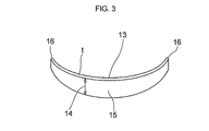
Fig. 3 is a perspective view of the half ring shown inFigs. 1 and2 . - Hereafter, a description will be given of the mode for carrying out the present invention with reference to an embodiment illustrated in the drawings.
-
Figs. 1 and2 show a state during an initial period of a lowering stroke of apiston 2 in an explosion and expansion stroke. -
Figs. 1 and2 show areciprocating engine 1 in accordance with this embodiment in an initial period of the explosion and expansion stroke. -
Reference numeral 2 denotes the piston, andreference numeral 3 denotes a cylinder. Further,reference numeral 4 denotes a gas chamber. - The
gas chamber 4 is formed by being encompassed by a cylinderinner surface 8 and a top ring 5, asecond ring 6, and asecond land 7 of thepiston 2. As for thegas chamber 4, itsvertical width 9 is wider on athrust side 10 and narrower on ananti-thrust side 11. - This is to ensure that, by making a gas-pressure receiving area wider on the
thrust side 10 and narrower on theanti-thrust side 11, thepiston 2 is supported from the thrust side 10 (in opposition to the lateral pressure of the piston) by a high-pressure combustion gas 12 introduced and held, to thereby make the pushback from theanti-thrust side 11 small. - In the
gas chamber 4, a circular arc-shapedhalf ring 13 is inserted in a state of being placed on thesecond land 7 from thethrust side 10. - In addition, the
half ring 13 is inserted in such a manner as to be movable up and down with clearances 17 above and below (in the reciprocating direction of the piston 2) inside thegas chamber 4. - As shown in
Fig. 3 , thehalf ring 13 is formed in a circular arc shape conforming to the circumferential surface of thesecond land 7. - In addition, as for the
half ring 13, its front side and lateral sides are formed such that itsvertical width 14 is made wide in a frontcentral portion 15 and narrower at bothside ends 16 in conformity with the shape of thegas chamber 4. - Further, the
vertical width 14 of thehalf ring 13, as a whole, is made shorter than thevertical width 9 of thegas chamber 4. This is to allow the clearances 17 to be created above and below in a state in which thehalf ring 13 is inserted in thegas chamber 4. Thehalf ring 13 moves up and down inside thegas chamber 4 an amount corresponding to the distance of these clearances 17. - As shown in
Figs. 1 and2 , thehalf ring 13 is inserted in thegas chamber 4 with its frontcentral portion 15 matched with thethrust side 10. - In particular, during the operation of the engine, the
half ring 13 is moved up and down by the reciprocating movement of thepiston 2 so as to vertically sweep the surface of thesecond land 7 for forming thegas chamber 4. - In addition, the thickness t of the
half ring 13 is such a thickness that, during the operation of the engine, thehalf ring 13 can freely move up and down (along the reciprocating direction of the piston 2) within aclearance 20 between the cylinderinner surface 8 and asurface 19 of thesecond land 7. - In addition, the
half ring 13 is formed of a metal plate, such as one formed of stainless steel, which is higher in heat insulating properties than a material for forming thepiston 2 which is formed of an aluminum alloy or the like. - It should be noted that, with respect to the
piston 2 of the reciprocatingengine 1 in accordance with this embodiment, the top ring 5 for forming thegas chamber 4 is provided in parallel to a pistontop surface 18, while thesecond ring 6 is provided in such a manner as to be inclined cowardly toward thethrust side 10. Namely, thesecond ring 6 is provided in such a manner as to be located away from the top ring 5 on thethrust side 10 and to be located closer to the top ring 5 as it approaches the anti-thrust side. - Accordingly, the interval (distance) between the top ring 5 and the
second ring 6, i.e., thevertical width 9 of thegas chamber 4, is wider on thethrust side 10 and becomes gradually narrower as it approaches theanti-thrust side 11. - In addition, a plurality of
gas passage holes 23 are provided in an upper portion 22 of the cylinderinner surface 8 on thethrust side 10. When the top ring 5 of the piston passes over thegas passage holes 23 in a lowering stroke of thepiston 2, acombustion chamber 25 above thepiston 2 and thegas chamber 4 of thepiston 2 communicate with each other throughrecesses 24 of thesegas passage holes 23, thereby allowing the high-pressure combustion gas 12 in thecombustion chamber 25 to be introduced into and held in thegas chamber 4. - Namely, in the initial period of the explosion and expansion stroke, when the top ring 5 of the
piston 2 passes thegas passage holes 23 in an upper portion of the cylinderinner surface 8, thecombustion chamber 25 above thepiston 2 and thegas chamber 4 of thepiston 2 communicate with each other, so that the high-pressure combustion gas 12 is introduced into and held in thegas chamber 4. - At this juncture, the
piston 2, upon receiving the action of the lateral pressure, tends to be pressed against the cylinderinner surface 8, but the piston is lowered during the lowering stroke in a state of being supported from the thrust side 10 (in opposition to the lateral pressure acting on the piston 2) by the high-pressure combustion gas introduced into and held in thegas chamber 4. - According to the
reciprocating engine 1 in accordance with this embodiment, during the operation of the engine, i.e., while thepiston 2 is reciprocating, the introduction (influx), holding, and discharge of thecombustion gas 12 are repeatedly carried out in thegas chamber 4 of thepiston 2, and thehalf ring 13 continues its up-down movement in thisgas chamber 4, thereby continually effecting cleaning action inside thegas chamber 4. For this reason, although thegas chamber 4 is repeatedly subjected to the introduction and holding of the high-pressure combustion gas 12, the occurrence of adhesion and deposition of carbon inside thegas chamber 4, particularly on such as thesurface 19 of thesecond land 7, is prevented by virtue of the cleaning action of thehalf ring 13. -
- 1:
- reciprocating engine
- 2:
- piston
- 3:
- cylinder
- 4:
- gas chamber
- 5:
- top ring
- 6:
- second ring
- 7:
- second land
- 8:
- cylinder inner surface
- 9:
- vertical width of gas chamber
- 10:
- thrust side
- 11:
- anti-thrust side
- 12:
- high-pressure combustion gas
- 13:
- half ring
- 14:
- vertical width of half ring
- 15:
- front central portion
- 16:
- both side ends
- 17:
- vertical clearance
- 18:
- piston top surface
- 19:
- surface of second land
- 20:
- clearance
- 22:
- upper portion
- 23:
- gas passage hole
- 24:
- recess
- 25:
- combustion chamber
Claims (2)
- A reciprocating engine in which, in an initial period of an expansion stroke, a high-pressure combustion gas from above a piston is introduced via gas passage holes provided in an upper portion of a cylinder inner surface on a thrust side into a gas chamber formed by being encompassed by the cylinder inner surface and a top ring, a second ring, and a second land of the piston, so as to support the piston from the thrust side by the introduced high-pressure combustion gas, said reciprocating engine comprising: a half ring which is inserted in the gas chamber in a state of being placed on the second land from the thrust side and so as to be movable up and down with clearances above and below, whereby as the piston reciprocates, the half ring moves up and down an amount corresponding to a size of the clearances, thereby continually cleaning an inside of the gas chamber.
- The reciprocating engine according to claim 1, wherein the half ring is formed of a metal plate which is higher in heat insulating properties than a material for forming the piston.
Applications Claiming Priority (3)
| Application Number | Priority Date | Filing Date | Title |
|---|---|---|---|
| JP2010020781A JP5287750B2 (en) | 2010-02-01 | 2010-02-01 | Reciprocating engine |
| JP2010175804 | 2010-08-04 | ||
| PCT/JP2011/000500 WO2011093106A1 (en) | 2010-02-01 | 2011-01-28 | Reciprocating engine |
Publications (3)
| Publication Number | Publication Date |
|---|---|
| EP2532871A1 true EP2532871A1 (en) | 2012-12-12 |
| EP2532871A4 EP2532871A4 (en) | 2015-01-14 |
| EP2532871B1 EP2532871B1 (en) | 2016-03-16 |
Family
ID=44319097
Family Applications (1)
| Application Number | Title | Priority Date | Filing Date |
|---|---|---|---|
| EP11736821.7A Not-in-force EP2532871B1 (en) | 2010-02-01 | 2011-01-28 | Reciprocating engine |
Country Status (5)
| Country | Link |
|---|---|
| US (2) | US9133788B2 (en) |
| EP (1) | EP2532871B1 (en) |
| KR (1) | KR101349064B1 (en) |
| CN (1) | CN102725503B (en) |
| WO (1) | WO2011093106A1 (en) |
Families Citing this family (3)
| Publication number | Priority date | Publication date | Assignee | Title |
|---|---|---|---|---|
| JP5630404B2 (en) * | 2011-06-13 | 2014-11-26 | 坂東機工株式会社 | Reciprocating engine |
| JP2013072346A (en) * | 2011-09-27 | 2013-04-22 | Bando Kiko Co Ltd | Reciprocating engine |
| US9745893B2 (en) | 2015-04-22 | 2017-08-29 | Ford Global Technologies, Llc | Hoop spring in a pressure reactive piston |
Citations (1)
| Publication number | Priority date | Publication date | Assignee | Title |
|---|---|---|---|---|
| WO1992002722A1 (en) * | 1990-08-03 | 1992-02-20 | Bando Kiko Co., Ltd. | Reciprocating engine |
Family Cites Families (15)
| Publication number | Priority date | Publication date | Assignee | Title |
|---|---|---|---|---|
| FR2594489B1 (en) * | 1986-02-14 | 1989-10-20 | Geffroy Robert | IMPROVED SCRAPER SEGMENT AND PISTON ASSEMBLY SLIDING IN CYLINDERS, SUCH AS AN INTERNAL COMBUSTION ENGINE COMPRISING SUCH SEGMENTS |
| JP2929771B2 (en) * | 1991-05-22 | 1999-08-03 | 坂東機工株式会社 | engine |
| JP2929777B2 (en) * | 1991-06-08 | 1999-08-03 | 坂東機工株式会社 | engine |
| JP3103395B2 (en) * | 1991-07-19 | 2000-10-30 | 坂東機工株式会社 | engine |
| KR970062277A (en) * | 1996-02-29 | 1997-09-12 | 도오다 고오이찌로 | Pistons for internal combustion engines |
| US5755192A (en) * | 1997-01-16 | 1998-05-26 | Ford Global Technologies, Inc. | Variable compression ratio piston |
| JP4362258B2 (en) | 1998-08-10 | 2009-11-11 | デュポン パフォーマンス エラストマーズ エルエルシー | Curable perfluoroelastomer composition |
| KR101108277B1 (en) | 2003-03-03 | 2012-01-31 | 반도키코 가부시키가이샤 | Reciprocating engine |
| CN100366883C (en) * | 2003-03-03 | 2008-02-06 | 坂东机工株式会社 | Reciprocating engine |
| DE102004013692A1 (en) * | 2004-03-18 | 2005-10-06 | Thyssenkrupp Transrapid Gmbh | Method for a magnetic levitation vehicle for controlling support columns and magnetic levitation vehicle with control circuits operating according to this method |
| WO2006117856A1 (en) | 2005-04-27 | 2006-11-09 | Bando Kiko Co., Ltd. | Reciprocating engine |
| KR101290739B1 (en) | 2006-10-20 | 2013-07-29 | 반도키코 가부시키가이샤 | Reciprocating engine |
| US7637241B2 (en) * | 2007-10-29 | 2009-12-29 | Ford Global Technologies | Pressure reactive piston for reciprocating internal combustion engine |
| JP2009114927A (en) * | 2007-11-05 | 2009-05-28 | Bando Kiko Co Ltd | Reciprocating engine |
| KR20100007702A (en) | 2008-07-14 | 2010-01-22 | 삼성전자주식회사 | Method and apparatus for producing animation |
-
2011
- 2011-01-28 US US13/576,510 patent/US9133788B2/en not_active Expired - Fee Related
- 2011-01-28 EP EP11736821.7A patent/EP2532871B1/en not_active Not-in-force
- 2011-01-28 CN CN201180007274.8A patent/CN102725503B/en not_active Expired - Fee Related
- 2011-01-28 WO PCT/JP2011/000500 patent/WO2011093106A1/en active Application Filing
- 2011-01-28 KR KR1020127019695A patent/KR101349064B1/en not_active IP Right Cessation
-
2013
- 2013-09-06 US US14/019,623 patent/US20140000548A1/en not_active Abandoned
Patent Citations (1)
| Publication number | Priority date | Publication date | Assignee | Title |
|---|---|---|---|---|
| WO1992002722A1 (en) * | 1990-08-03 | 1992-02-20 | Bando Kiko Co., Ltd. | Reciprocating engine |
Non-Patent Citations (1)
| Title |
|---|
| See also references of WO2011093106A1 * |
Also Published As
| Publication number | Publication date |
|---|---|
| EP2532871A4 (en) | 2015-01-14 |
| KR101349064B1 (en) | 2014-01-08 |
| EP2532871B1 (en) | 2016-03-16 |
| CN102725503A (en) | 2012-10-10 |
| KR20120099141A (en) | 2012-09-06 |
| US20140000548A1 (en) | 2014-01-02 |
| US9133788B2 (en) | 2015-09-15 |
| US20120298084A1 (en) | 2012-11-29 |
| WO2011093106A1 (en) | 2011-08-04 |
| CN102725503B (en) | 2015-08-26 |
Similar Documents
| Publication | Publication Date | Title |
|---|---|---|
| EP2532871A1 (en) | Reciprocating engine | |
| EP3040526A1 (en) | Multi-material valve guide system and method | |
| US10107228B2 (en) | Internal combustion engine cylinder liner flange with non-circular profile | |
| JP2016169791A (en) | Side rail | |
| EP2963254B1 (en) | Columnar hydraulic tappet | |
| EP2905453A1 (en) | Cylinder liner with striking-off edge | |
| KR20140123587A (en) | Piston ring for an internal combustion engine | |
| JP5287750B2 (en) | Reciprocating engine | |
| JP5533835B2 (en) | Reciprocating engine | |
| JP5534082B2 (en) | Reciprocating engine | |
| CN109386398A (en) | Fatigue resistance piston bowl rim | |
| KR20130029821A (en) | Cooling structure for internal combustion engine | |
| US20150211636A1 (en) | High temperature seal assembly | |
| JP5747448B2 (en) | Punching hole punching and punching hole machining method with improved fatigue characteristics and hydrogen cracking resistance | |
| JP5630404B2 (en) | Reciprocating engine | |
| JPWO2012017590A1 (en) | Reciprocating engine | |
| WO2014118827A1 (en) | Reciprocating engine | |
| JP2011007076A (en) | Reciprocating engine | |
| JP2013072297A (en) | Reciprocating engine | |
| JP2013072346A (en) | Reciprocating engine | |
| CN206738016U (en) | A kind of cylinder jacket | |
| JP2010172938A (en) | Internal chilling method and piston body | |
| JP6308192B2 (en) | Reciprocating engine | |
| JP2007040470A (en) | Piston ring and piston device | |
| RU2651694C1 (en) | Internal combustion engine sleeve assembly |
Legal Events
| Date | Code | Title | Description |
|---|---|---|---|
| PUAI | Public reference made under article 153(3) epc to a published international application that has entered the european phase |
Free format text: ORIGINAL CODE: 0009012 |
|
| 17P | Request for examination filed |
Effective date: 20120720 |
|
| AK | Designated contracting states |
Kind code of ref document: A1 Designated state(s): AL AT BE BG CH CY CZ DE DK EE ES FI FR GB GR HR HU IE IS IT LI LT LU LV MC MK MT NL NO PL PT RO RS SE SI SK SM TR |
|
| DAX | Request for extension of the european patent (deleted) | ||
| A4 | Supplementary search report drawn up and despatched |
Effective date: 20141215 |
|
| RIC1 | Information provided on ipc code assigned before grant |
Ipc: F02B 77/04 20060101ALI20141209BHEP Ipc: F02F 3/00 20060101AFI20141209BHEP Ipc: F02F 1/18 20060101ALI20141209BHEP Ipc: F16J 1/02 20060101ALI20141209BHEP Ipc: F16J 9/00 20060101ALI20141209BHEP |
|
| GRAP | Despatch of communication of intention to grant a patent |
Free format text: ORIGINAL CODE: EPIDOSNIGR1 |
|
| RIC1 | Information provided on ipc code assigned before grant |
Ipc: F16J 9/00 20060101ALI20150728BHEP Ipc: F02F 1/18 20060101ALI20150728BHEP Ipc: F16J 1/02 20060101ALI20150728BHEP Ipc: F02B 77/04 20060101ALI20150728BHEP Ipc: F02F 3/00 20060101AFI20150728BHEP |
|
| INTG | Intention to grant announced |
Effective date: 20150818 |
|
| GRAS | Grant fee paid |
Free format text: ORIGINAL CODE: EPIDOSNIGR3 |
|
| GRAA | (expected) grant |
Free format text: ORIGINAL CODE: 0009210 |
|
| AK | Designated contracting states |
Kind code of ref document: B1 Designated state(s): AL AT BE BG CH CY CZ DE DK EE ES FI FR GB GR HR HU IE IS IT LI LT LU LV MC MK MT NL NO PL PT RO RS SE SI SK SM TR |
|
| REG | Reference to a national code |
Ref country code: GB Ref legal event code: FG4D |
|
| REG | Reference to a national code |
Ref country code: CH Ref legal event code: EP |
|
| REG | Reference to a national code |
Ref country code: IE Ref legal event code: FG4D |
|
| REG | Reference to a national code |
Ref country code: AT Ref legal event code: REF Ref document number: 781475 Country of ref document: AT Kind code of ref document: T Effective date: 20160415 |
|
| REG | Reference to a national code |
Ref country code: DE Ref legal event code: R096 Ref document number: 602011024062 Country of ref document: DE |
|
| REG | Reference to a national code |
Ref country code: NL Ref legal event code: MP Effective date: 20160316 |
|
| REG | Reference to a national code |
Ref country code: LT Ref legal event code: MG4D |
|
| PG25 | Lapsed in a contracting state [announced via postgrant information from national office to epo] |
Ref country code: HR Free format text: LAPSE BECAUSE OF FAILURE TO SUBMIT A TRANSLATION OF THE DESCRIPTION OR TO PAY THE FEE WITHIN THE PRESCRIBED TIME-LIMIT Effective date: 20160316 Ref country code: GR Free format text: LAPSE BECAUSE OF FAILURE TO SUBMIT A TRANSLATION OF THE DESCRIPTION OR TO PAY THE FEE WITHIN THE PRESCRIBED TIME-LIMIT Effective date: 20160617 Ref country code: NO Free format text: LAPSE BECAUSE OF FAILURE TO SUBMIT A TRANSLATION OF THE DESCRIPTION OR TO PAY THE FEE WITHIN THE PRESCRIBED TIME-LIMIT Effective date: 20160616 |
|
| REG | Reference to a national code |
Ref country code: AT Ref legal event code: MK05 Ref document number: 781475 Country of ref document: AT Kind code of ref document: T Effective date: 20160316 |
|
| PG25 | Lapsed in a contracting state [announced via postgrant information from national office to epo] |
Ref country code: LT Free format text: LAPSE BECAUSE OF FAILURE TO SUBMIT A TRANSLATION OF THE DESCRIPTION OR TO PAY THE FEE WITHIN THE PRESCRIBED TIME-LIMIT Effective date: 20160316 Ref country code: SE Free format text: LAPSE BECAUSE OF FAILURE TO SUBMIT A TRANSLATION OF THE DESCRIPTION OR TO PAY THE FEE WITHIN THE PRESCRIBED TIME-LIMIT Effective date: 20160316 Ref country code: NL Free format text: LAPSE BECAUSE OF FAILURE TO SUBMIT A TRANSLATION OF THE DESCRIPTION OR TO PAY THE FEE WITHIN THE PRESCRIBED TIME-LIMIT Effective date: 20160316 Ref country code: RS Free format text: LAPSE BECAUSE OF FAILURE TO SUBMIT A TRANSLATION OF THE DESCRIPTION OR TO PAY THE FEE WITHIN THE PRESCRIBED TIME-LIMIT Effective date: 20160316 Ref country code: LV Free format text: LAPSE BECAUSE OF FAILURE TO SUBMIT A TRANSLATION OF THE DESCRIPTION OR TO PAY THE FEE WITHIN THE PRESCRIBED TIME-LIMIT Effective date: 20160316 |
|
| PG25 | Lapsed in a contracting state [announced via postgrant information from national office to epo] |
Ref country code: PL Free format text: LAPSE BECAUSE OF FAILURE TO SUBMIT A TRANSLATION OF THE DESCRIPTION OR TO PAY THE FEE WITHIN THE PRESCRIBED TIME-LIMIT Effective date: 20160316 Ref country code: IS Free format text: LAPSE BECAUSE OF FAILURE TO SUBMIT A TRANSLATION OF THE DESCRIPTION OR TO PAY THE FEE WITHIN THE PRESCRIBED TIME-LIMIT Effective date: 20160716 Ref country code: EE Free format text: LAPSE BECAUSE OF FAILURE TO SUBMIT A TRANSLATION OF THE DESCRIPTION OR TO PAY THE FEE WITHIN THE PRESCRIBED TIME-LIMIT Effective date: 20160316 |
|
| PG25 | Lapsed in a contracting state [announced via postgrant information from national office to epo] |
Ref country code: SK Free format text: LAPSE BECAUSE OF FAILURE TO SUBMIT A TRANSLATION OF THE DESCRIPTION OR TO PAY THE FEE WITHIN THE PRESCRIBED TIME-LIMIT Effective date: 20160316 Ref country code: SM Free format text: LAPSE BECAUSE OF FAILURE TO SUBMIT A TRANSLATION OF THE DESCRIPTION OR TO PAY THE FEE WITHIN THE PRESCRIBED TIME-LIMIT Effective date: 20160316 Ref country code: PT Free format text: LAPSE BECAUSE OF FAILURE TO SUBMIT A TRANSLATION OF THE DESCRIPTION OR TO PAY THE FEE WITHIN THE PRESCRIBED TIME-LIMIT Effective date: 20160718 Ref country code: ES Free format text: LAPSE BECAUSE OF FAILURE TO SUBMIT A TRANSLATION OF THE DESCRIPTION OR TO PAY THE FEE WITHIN THE PRESCRIBED TIME-LIMIT Effective date: 20160316 Ref country code: CZ Free format text: LAPSE BECAUSE OF FAILURE TO SUBMIT A TRANSLATION OF THE DESCRIPTION OR TO PAY THE FEE WITHIN THE PRESCRIBED TIME-LIMIT Effective date: 20160316 Ref country code: AT Free format text: LAPSE BECAUSE OF FAILURE TO SUBMIT A TRANSLATION OF THE DESCRIPTION OR TO PAY THE FEE WITHIN THE PRESCRIBED TIME-LIMIT Effective date: 20160316 Ref country code: RO Free format text: LAPSE BECAUSE OF FAILURE TO SUBMIT A TRANSLATION OF THE DESCRIPTION OR TO PAY THE FEE WITHIN THE PRESCRIBED TIME-LIMIT Effective date: 20160316 |
|
| REG | Reference to a national code |
Ref country code: DE Ref legal event code: R097 Ref document number: 602011024062 Country of ref document: DE |
|
| PG25 | Lapsed in a contracting state [announced via postgrant information from national office to epo] |
Ref country code: BE Free format text: LAPSE BECAUSE OF FAILURE TO SUBMIT A TRANSLATION OF THE DESCRIPTION OR TO PAY THE FEE WITHIN THE PRESCRIBED TIME-LIMIT Effective date: 20160316 Ref country code: IT Free format text: LAPSE BECAUSE OF FAILURE TO SUBMIT A TRANSLATION OF THE DESCRIPTION OR TO PAY THE FEE WITHIN THE PRESCRIBED TIME-LIMIT Effective date: 20160316 |
|
| PLBE | No opposition filed within time limit |
Free format text: ORIGINAL CODE: 0009261 |
|
| STAA | Information on the status of an ep patent application or granted ep patent |
Free format text: STATUS: NO OPPOSITION FILED WITHIN TIME LIMIT |
|
| PG25 | Lapsed in a contracting state [announced via postgrant information from national office to epo] |
Ref country code: DK Free format text: LAPSE BECAUSE OF FAILURE TO SUBMIT A TRANSLATION OF THE DESCRIPTION OR TO PAY THE FEE WITHIN THE PRESCRIBED TIME-LIMIT Effective date: 20160316 |
|
| 26N | No opposition filed |
Effective date: 20161219 |
|
| PG25 | Lapsed in a contracting state [announced via postgrant information from national office to epo] |
Ref country code: BG Free format text: LAPSE BECAUSE OF FAILURE TO SUBMIT A TRANSLATION OF THE DESCRIPTION OR TO PAY THE FEE WITHIN THE PRESCRIBED TIME-LIMIT Effective date: 20160616 |
|
| PG25 | Lapsed in a contracting state [announced via postgrant information from national office to epo] |
Ref country code: SI Free format text: LAPSE BECAUSE OF FAILURE TO SUBMIT A TRANSLATION OF THE DESCRIPTION OR TO PAY THE FEE WITHIN THE PRESCRIBED TIME-LIMIT Effective date: 20160316 |
|
| REG | Reference to a national code |
Ref country code: DE Ref legal event code: R119 Ref document number: 602011024062 Country of ref document: DE |
|
| REG | Reference to a national code |
Ref country code: CH Ref legal event code: PL |
|
| GBPC | Gb: european patent ceased through non-payment of renewal fee |
Effective date: 20170128 |
|
| PG25 | Lapsed in a contracting state [announced via postgrant information from national office to epo] |
Ref country code: MC Free format text: LAPSE BECAUSE OF FAILURE TO SUBMIT A TRANSLATION OF THE DESCRIPTION OR TO PAY THE FEE WITHIN THE PRESCRIBED TIME-LIMIT Effective date: 20160316 |
|
| REG | Reference to a national code |
Ref country code: FR Ref legal event code: ST Effective date: 20170929 |
|
| PG25 | Lapsed in a contracting state [announced via postgrant information from national office to epo] |
Ref country code: LI Free format text: LAPSE BECAUSE OF NON-PAYMENT OF DUE FEES Effective date: 20170131 Ref country code: CH Free format text: LAPSE BECAUSE OF NON-PAYMENT OF DUE FEES Effective date: 20170131 Ref country code: FI Free format text: LAPSE BECAUSE OF NON-PAYMENT OF DUE FEES Effective date: 20170128 Ref country code: FR Free format text: LAPSE BECAUSE OF NON-PAYMENT OF DUE FEES Effective date: 20170131 |
|
| REG | Reference to a national code |
Ref country code: IE Ref legal event code: MM4A |
|
| PG25 | Lapsed in a contracting state [announced via postgrant information from national office to epo] |
Ref country code: GB Free format text: LAPSE BECAUSE OF NON-PAYMENT OF DUE FEES Effective date: 20170128 Ref country code: DE Free format text: LAPSE BECAUSE OF NON-PAYMENT OF DUE FEES Effective date: 20170801 Ref country code: LU Free format text: LAPSE BECAUSE OF NON-PAYMENT OF DUE FEES Effective date: 20170128 |
|
| PG25 | Lapsed in a contracting state [announced via postgrant information from national office to epo] |
Ref country code: IE Free format text: LAPSE BECAUSE OF NON-PAYMENT OF DUE FEES Effective date: 20170128 |
|
| PG25 | Lapsed in a contracting state [announced via postgrant information from national office to epo] |
Ref country code: MT Free format text: LAPSE BECAUSE OF NON-PAYMENT OF DUE FEES Effective date: 20170128 |
|
| PG25 | Lapsed in a contracting state [announced via postgrant information from national office to epo] |
Ref country code: AL Free format text: LAPSE BECAUSE OF FAILURE TO SUBMIT A TRANSLATION OF THE DESCRIPTION OR TO PAY THE FEE WITHIN THE PRESCRIBED TIME-LIMIT Effective date: 20160316 |
|
| PG25 | Lapsed in a contracting state [announced via postgrant information from national office to epo] |
Ref country code: HU Free format text: LAPSE BECAUSE OF FAILURE TO SUBMIT A TRANSLATION OF THE DESCRIPTION OR TO PAY THE FEE WITHIN THE PRESCRIBED TIME-LIMIT; INVALID AB INITIO Effective date: 20110128 |
|
| PG25 | Lapsed in a contracting state [announced via postgrant information from national office to epo] |
Ref country code: CY Free format text: LAPSE BECAUSE OF NON-PAYMENT OF DUE FEES Effective date: 20160316 |
|
| PG25 | Lapsed in a contracting state [announced via postgrant information from national office to epo] |
Ref country code: MK Free format text: LAPSE BECAUSE OF FAILURE TO SUBMIT A TRANSLATION OF THE DESCRIPTION OR TO PAY THE FEE WITHIN THE PRESCRIBED TIME-LIMIT Effective date: 20160316 |
|
| PG25 | Lapsed in a contracting state [announced via postgrant information from national office to epo] |
Ref country code: TR Free format text: LAPSE BECAUSE OF FAILURE TO SUBMIT A TRANSLATION OF THE DESCRIPTION OR TO PAY THE FEE WITHIN THE PRESCRIBED TIME-LIMIT Effective date: 20160316 |