EP2532451A1 - Verfahren und Vorrichtung zur Vermeidung von Reibmartensit beim Ziehschälen eines Drahts - Google Patents
Verfahren und Vorrichtung zur Vermeidung von Reibmartensit beim Ziehschälen eines Drahts Download PDFInfo
- Publication number
- EP2532451A1 EP2532451A1 EP11169138A EP11169138A EP2532451A1 EP 2532451 A1 EP2532451 A1 EP 2532451A1 EP 11169138 A EP11169138 A EP 11169138A EP 11169138 A EP11169138 A EP 11169138A EP 2532451 A1 EP2532451 A1 EP 2532451A1
- Authority
- EP
- European Patent Office
- Prior art keywords
- wire
- machining
- processing element
- processing
- cooling gas
- Prior art date
- Legal status (The legal status is an assumption and is not a legal conclusion. Google has not performed a legal analysis and makes no representation as to the accuracy of the status listed.)
- Granted
Links
Images

Classifications
-
- B—PERFORMING OPERATIONS; TRANSPORTING
- B21—MECHANICAL METAL-WORKING WITHOUT ESSENTIALLY REMOVING MATERIAL; PUNCHING METAL
- B21C—MANUFACTURE OF METAL SHEETS, WIRE, RODS, TUBES, PROFILES OR LIKE SEMI-MANUFACTURED PRODUCTS OTHERWISE THAN BY ROLLING; AUXILIARY OPERATIONS USED IN CONNECTION WITH METAL-WORKING WITHOUT ESSENTIALLY REMOVING MATERIAL
- B21C9/00—Cooling, heating or lubricating drawing material
-
- B—PERFORMING OPERATIONS; TRANSPORTING
- B21—MECHANICAL METAL-WORKING WITHOUT ESSENTIALLY REMOVING MATERIAL; PUNCHING METAL
- B21C—MANUFACTURE OF METAL SHEETS, WIRE, RODS, TUBES, PROFILES OR LIKE SEMI-MANUFACTURED PRODUCTS OTHERWISE THAN BY ROLLING; AUXILIARY OPERATIONS USED IN CONNECTION WITH METAL-WORKING WITHOUT ESSENTIALLY REMOVING MATERIAL
- B21C43/00—Devices for cleaning metal products combined with or specially adapted for use with machines or apparatus provided for in this subclass
- B21C43/02—Devices for cleaning metal products combined with or specially adapted for use with machines or apparatus provided for in this subclass combined with or specially adapted for use in connection with drawing or winding machines or apparatus
-
- B—PERFORMING OPERATIONS; TRANSPORTING
- B23—MACHINE TOOLS; METAL-WORKING NOT OTHERWISE PROVIDED FOR
- B23D—PLANING; SLOTTING; SHEARING; BROACHING; SAWING; FILING; SCRAPING; LIKE OPERATIONS FOR WORKING METAL BY REMOVING MATERIAL, NOT OTHERWISE PROVIDED FOR
- B23D79/00—Methods, machines, or devices not covered elsewhere, for working metal by removal of material
- B23D79/12—Machines or devices for peeling bars or tubes making use of cutting bits arranged around the workpiece, otherwise than by turning
Definitions
- the present invention relates to a method for cooling a wire and a machining apparatus for machining the wire.
- the invention relates to a method of cooling a wire during draw peeling and a corresponding draw peeling device.
- the starting material which has surface defects and geometric deviations, are first pulled by means of a drawing disc through one or more dies.
- the starting material is plastically deformed and has a smaller diameter after the die than before the die.
- the wire is pulled through a peeling stone, whereby the outermost layer of the wire is removed by machining.
- the cutting forces occurring during peeling briefly generate such a high frictional heat, which can lead to an undesirable microstructural change on the wire surface.
- a Reibmartensit can form on the wire surface.
- the Reibmartensit is not plastically deformable due to its hardness, further wire drawing operations are not possible.
- the present invention has the object, at least partially to solve the problems described with reference to the prior art and in particular to provide a method and an apparatus that make a subsequent heat treatment unnecessary.
- a contact point between the at least one first processing element and the wire and / or a cut-free region of the at least one first processing element is acted upon by the gas.
- free cutting area is meant the area of the cutting clearance angle of the at least one first processing element in the drawing direction behind the point of contact between peeling stone and wire.
- the method is therefore particularly suitable for operating a drawing peeling device for producing thin wire with high surface quality.
- the wire produced in the process is free of cracks, defects and Reibmartensit and has a bare surface.
- the gas can be removed by means of a suction device.
- the wire is usually conveyed by means of a drawing disc by the drawing peeling device.
- the first processing element is in particular a peeling stone, on which the uppermost layer of the wire is peeled off.
- the cooling gas is preferably guided by lines in the ZiehMlvorraum and exits through one or more nozzle, which is directed to the wire surface and / or the first processing element. In particular, the nozzle is directed into the free-cutting area between the wire surface and the first processing element.
- the cooling gas is preferably a cryogenic liquefied gas under pressure which, if it leaves the nozzle, possibly changes the state of aggregation.
- gaseous, liquid and / or solid cooling gas under Pressure and high exit velocity reaches deep in the region of the contact point between the first processing element and wire.
- a cooling gas having a temperature of preferably below 0 ° C, in particular below -50 ° C or even - 75 ° C a short-term increase in the surface temperature of the wire over the critical martensite formation temperature is avoided.
- the wire is thus plastically deformable without subsequent heat treatment in further drawing operations. On the cost and energy intensive subsequent heat treatment can be dispensed with.
- the wire surface produced in this way can be described as bare and clean. Oxides on the surface produced by a heat treatment do not occur.
- the next step can be performed without descaling and / or pickling the surface.
- the wire through at least a second processing element, in particular a die for plastic deformation of the wire in the direction of the wire in front of the first processing element within and / or outside of the processing device to be led.
- the wire can be cooled by the refrigerant gas when passing through the second processing element or the second processing element.
- the wire is passed through at least one second processing element for plastic deformation, in particular a die, of the wire in the direction of the wire after the first processing element inside and / or outside Machining device is guided.
- the second processing element within the processing device can also at this rejuvenation process of the wire, the wire and / or the second processing element are cooled with the cooling gas.
- the second processing element is charged with a cooling gas.
- the wire in the immediate vicinity of the processing element and / or the first processing element is acted upon by a location in the wire running direction behind the first processing element with the cooling gas.
- the nozzle is directed towards the point of contact and / or the cut-free area between the wire and the processing element counter to the wire running direction for applying cooling gas.
- the feeder comprises at least one duct which is arranged and equipped for guiding the pressurized cooling gas and at least one nozzle connected to the duct for charging the wire or the processing apparatus with the cooling gas.
- the processing element is in particular a processing element for machining the wire.
- the nozzle can be configured and / or operated such that, upon exiting the nozzle, a phase transition of the cooling gas, that is to say an at least partial change of the state of matter, takes place.
- the machining device has at least one second machining element for plastic deformation in the wire running direction at least in front of and / or behind the first machining element.
- the second processing element is in particular a die.
- the wire can be tapered in front of or behind the first processing element, wherein at the same time a cooling can take place in the plastic deformation step.
- the first processing element is a peel and the second processing element is a die.
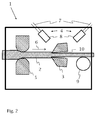
- the FIG. 1 shows schematically in cross section a processing apparatus 1 according to the present invention.
- the processing device 1 is in particular a drawing peeling device.
- the processing device 1 comprises a peeling stone 3 as the first processing element, as well as a drawing disk 9.
- the processing device 1 comprises a feed 4 with a line 7 and a nozzle 8 for supplying a cooling gas.
- a wire 2 is pulled in the wire running direction 6 of the drawing disk 9 by the processing device 1.
- the wire 2 passes through the peeling stone 3, where the uppermost layer of the wire 2 is peeled off by cutting. This improves the quality of the surface of the wire 2.
- the cooling gas is in particular liquid carbon dioxide, which changes its state of aggregation on exiting the nozzle 8 and impinges on the wire 2 and the peeling stone 3 as carbon dioxide snow or carbon dioxide gas or liquid nitrogen in liquid or gaseous form in the narrow gap between the wire 2 and the peeling stone 3, the free-cutting area 10, arrives.
- the wire 2 and the first processing element 3, in particular a peeling stone 3 are cooled so strongly that an increase in temperature of the surface of the wire during peeling to a temperature above a critical martensite formation temperature does not take place. Therefore, can be dispensed with a costly and energy-intensive, downstream heat treatment.
- FIG. 2 shows schematically in cross section a further embodiment of a processing apparatus 1 according to the present invention.
- the processing apparatus 1 comprises a die 5 as a second processing element and a peel stone 3 as a first processing element, and a drawing disk 9. Further, the processing device 1 comprises two feeds 4 each having a conduit 7 and a nozzle 8 for supplying a cooling gas.
- a wire 2 is pulled in the wire running direction 6 of the drawing disk 9 by the processing device 1.
- the wire 2 first passes through the die 5, whereby the wire 2 is plastically deformed and its cross section is tapered. Subsequently, the wire 2 passes through the peeling stone 3, where the uppermost layer of the wire 2 is peeled off by cutting.
Landscapes
- Engineering & Computer Science (AREA)
- Mechanical Engineering (AREA)
- Physics & Mathematics (AREA)
- Optics & Photonics (AREA)
- Metal Extraction Processes (AREA)
- Heat Treatment Of Strip Materials And Filament Materials (AREA)
Abstract
Description
- Die vorliegende Erfindung betrifft ein Verfahren zur Kühlung eines Drahts und eine Bearbeitungsvorrichtung zur spanenden Bearbeitung des Drahts. Insbesondere betrifft die Erfindung ein Verfahren zum Kühlen eines Drahts beim Ziehschälen und eine entsprechende Ziehschälvorrichtung.
- In Ziehschälvorrichtungen werden dünne Drähte mit hoher Oberflächenqualität hergestellt. Dabei kann das Ausgangsmaterial, welches Oberflächenfehler und geometrische Abweichungen aufweist, zunächst mit Hilfe einer Ziehscheibe durch einen oder mehrere Ziehsteine gezogen werden. Hierbei wird das Ausgangsmaterial plastisch verformt und weist nach dem Ziehstein einen kleineren Durchmesser als vor dem Ziehstein auf. Um die Oberflächenqualität zu verbessern, wird der Draht durch einen Schälstein gezogen, wobei die äußerste Schicht des Drahts durch spanende Bearbeitung abgetragen wird.
- Die beim Schälen auftretenden Schneidkräfte erzeugen kurzzeitig eine so hohe Reibungswärme, die zu einer unerwünschten Gefügeveränderung auf der Drahtoberfläche führen kann. Auf der Drahtoberfläche kann sich insbesondere ein Reibmartensit ausbilden. Das Reibmartensit ist aufgrund seiner Härte nicht plastisch verformbar, weitere Drahtziehoperationen sind nicht möglich.
- Stand der Technik ist es, den Draht und den Schälstein mit Wasser zu kühlen. Dabei ist die Kühlleistung des Wassers jedoch nicht ausreichend, um eine Reibmartensitbildung zu verhindern. Dies liegt darin begründet, dass das Kühlwasser kritische Punkte nicht erreicht. Kritische Punkte sind der Kontaktpunkt zwischen Schälstein und Draht und der Bereich des Schneidenfreiwinkels des Schälsteins in Ziehrichtung hinter dem Kontaktpunkt zwischen Schälstein und Draht, der auch Freischneidenbereich genannt wird.
- Es ist daher bekannt, dass Reibmartensit nach dem Schälvorgang durch eine gezielte Wärmebehandlung, durch das sogenannte Lösungsglühen, vollständig aufzulösen. Dieses Lösungsglühen ist ein zusätzlicher, aufwendiger Arbeitsgang mit hohem Energieaufwand.
- Hiervon ausgehend liegt der vorliegenden Erfindung die Aufgabe zugrunde, die mit Bezug auf den Stand der Technik geschilderten Probleme zumindest teilweise zu lösen und insbesondere ein Verfahren und eine Vorrichtung anzugeben, die eine nachträgliche Wärmebehandlung überflüssig machen.
- Diese Aufgaben werden gelöst mit einem Verfahren und einer Bearbeitungsvorrichtung gemäß den Merkmalen der unabhängigen Patentansprüche. Weitere vorteilhafte Ausgestaltungen der Erfindung sind in den jeweils abhängig formulierten Patentansprüchen angegeben. Die in den Patentansprüchen einzeln aufgeführten Merkmale sind in beliebiger, technologisch sinnvoller Weise miteinander kombinierbar und können durch erläuternde Sachverhalte aus der Beschreibung ergänzt werden, wobei weitere Ausführungsvarianten der Erfindung aufgezeigt werden.
- Insbesondere werden die Aufgaben gelöst durch ein Verfahren zum Kühlen eines Drahts mit einer Drahtoberfläche, umfassend zumindest die folgenden Schritte:
- Hineinführen des Drahts in eine Bearbeitungsvorrichtung,
- Führen des Drahts durch mindestens ein erstes Bearbeitungselement zur spanenden Bearbeitung der Drahtoberfläche,
- Beaufschlagen zumindest der Drahtoberfläche oder des ersten Bearbeitungselements in der Bearbeitungsvorrichtung mit einem Kühlgas, insbesondere einem tiefkalten Gas.
- Insbesondere wird ein Kontaktpunkt zwischen dem mindestens einen ersten Bearbeitungselement und dem Draht und/oder ein Freischneidenbereich des mindestens einen ersten Bearbeitungselements mit dem Gas beaufschlagt. Mit Freischneidenbereich ist der Bereich des Schneidenfreiwinkels des mindestens einen ersten Bearbeitungselements in Ziehrichtung hinter dem Kontaktpunkt zwischen Schälstein und Draht gemeint.
- Das Verfahren ist somit insbesondere geeignet zum Betreiben einer Ziehschälvorrichtung zur Herstellung von dünnem Draht mit hoher Oberflächenqualität. Der in dem Verfahren hergestellte Draht ist frei von Rissen, Fehlern und Reibmartensit und weist eine blanke Oberfläche auf. Durch den Einsatz von kalten Gasen zum Kühlen werden die Bearbeitungsvorrichtung sowie der Draht nicht verschmutzt. Das Gas kann mittels einer Absaugvorrichtung entfernt werden.
- Der Draht wird in der Regel mit Hilfe einer Ziehscheibe durch die Ziehschälvorrichtung gefördert. Das erste Bearbeitungselement ist insbesondere ein Schälstein, an dem die oberste Schicht des Drahts abgeschält wird. Das Kühlgas wird bevorzugt mit Leitungen in die Ziehschälvorrichtung geführt und tritt durch eine oder mehrere Düse aus, die auf die Drahtoberfläche und/oder das erste Bearbeitungselement gerichtet ist. Insbesondere ist die Düse in den Freischneidenbereich zwischen Drahtoberfläche und erstem Bearbeitungselement gerichtet.
- Das Kühlgas ist bevorzugt ein kälteverflüssigtes Gas unter Druck, welches bei Austritt aus der Düse ggf. den Aggregatszustand ändert. Somit wird erreicht, dass gasförmiges, flüssiges und/oder festes Kühlgas unter Druck und hoher Austrittsgeschwindigkeit tief in den Bereich des Kontaktpunkts zwischen erstem Bearbeitungselement und Draht gelangt. Durch die Verwendung eines Kühlgases mit einer Temperatur von bevorzugt unterhalb von 0 °C, insbesondere von unterhalb -50°C oder sogar - 75°C wird ein kurzfristiges Ansteigen der Oberflächentemperatur des Drahts über die kritische Martensitbildungstemperatur vermieden. Der Draht ist somit ohne eine nachfolgende Wärmebehandlung in weiteren Ziehvorgängen plastisch verformbar. Auf die kosten- und energieintensive nachträgliche Wärmebehandlung kann verzichtet werden. Die so erzeugte Drahtoberfläche kann als blank und sauber bezeichnet werden. Durch eine Wärmebehandlung erzeugte Oxide auf der Oberfläche treten nicht auf. Der nächste Arbeitsschritt kann ohne entzundern und/oder Beizen der Oberfläche durchgeführt werden.
- Um den Draht vor dem Schälen zu verjüngen, wird in einer Weiterbildung der Erfindung vorgeschlagen, dass der Draht durch mindestens ein zweites Bearbeitungselement, insbesondere einen Ziehstein, zur plastischen Verformung des Drahts in Laufrichtung des Drahts vor dem ersten Bearbeitungselement innerhalb und/oder außerhalb der Bearbeitungsvorrichtung geführt wird. Bei der Anordnung des zweiten Bearbeitungselements in der Bearbeitungsvorrichtung kann der Draht beim Durchgang durch das zweite Bearbeitungselement beziehungsweise das zweite Bearbeitungselement durch das Kühlgas gekühlt werden.
- Um den Draht nach dem Schälen zu verjüngen, wird in einer vorteilhaften Weiterbildung der Erfindung vorgeschlagen, dass der Draht durch mindestens ein zweites Bearbeitungselement zur plastischen Verformung, insbesondere einen Ziehstein, des Drahts in Laufrichtung des Drahts nach dem ersten Bearbeitungselement innerhalb und/oder außerhalb der Bearbeitungsvorrichtung geführt wird. Bei der Anordnung des zweiten Bearbeitungselements innerhalb der Bearbeitungsvorrichtung kann auch bei diesem Verjüngungsprozess des Drahts der Draht und/oder das zweite Bearbeitungselement mit dem Kühlgas gekühlt werden.
- Ferner wird vorgeschlagen, dass auch das zweite Bearbeitungselement mit einem Kühlgas beaufschlagt wird.
- Um eine effiziente Kühlung des Drahts und/oder des ersten Bearbeitungselements zu erhalten, wird vorgeschlagen, dass der Draht in unmittelbarer Nähe des Bearbeitungselements und/oder das erste Bearbeitungselement von einer Stelle in Drahtlaufrichtung hinter dem ersten Bearbeitungselement mit dem Kühlgas beaufschlagt wird. Damit ist insbesondere gemeint, dass die Düse zum Beaufschlagen mit Kühlgas auf den Kontaktpunkt und/oder den Freischneidenbereich zwischen Draht und Bearbeitungselement entgegen der Drahtlaufrichtung gerichtet ist.
- Vorteilhaft umfasst das Kühlgas wenigstens ein Element der folgenden Gruppe, wenn es mit dem Draht und/oder dem ersten Bearbeitungselement in Kontakt kommt:
- festes Kohlendioxid (CO2-Schnee),
- flüssiger Stickstoff (N2),
- gasförmiges Kohlendioxid (CO2) mit einer Temperatur unterhalb von -10 °C,
- gasförmiger Stickstoff mit einer Temperatur unterhalb von - 50 °C
- Einem weiteren Aspekt der Erfindung folgend wird eine Bearbeitungsvorrichtung, insbesondere eine Ziehschälvorrichtung zum spanenden Bearbeiten des Drahts vorgeschlagen, umfassend mindestens ein erstes Bearbeitungselement und eine Zuführung für ein Kühlgas, die so angeordnet und ausgerichtet ist, dass mindestens eines der folgenden Elemente:
- der Draht und
- das erste Bearbeitungselement
- Die Zuführung umfasst zumindest eine Leitung, die eingerichtet und ausgestattet ist zum Führen des unter Druck stehenden Kühlgases und mindestens eine an die Leitung angeschlossene Düse zum Beaufschlagen des Drahts oder der Bearbeitungsvorrichtung mit dem Kühlgas. Das Bearbeitungselement ist insbesondere ein Bearbeitungselement zur spanenden Bearbeitung des Drahts. Mit der erfindungsgemäßen Bearbeitungsvorrichtung kann auf eine nachträgliche Wärmebehandlung nach dem Schälprozess verzichtet werden. Die Düse kann insbesondere so ausgestaltet sein und/oder betrieben werden, dass beim Austritt aus der Düse ein Phasenübergang des Kühlgases, also eine zumindest teilweise Änderung des Aggregatzustandes, stattfindet.
- Gemäß einer vorteilhaften Weiterbildung der Bearbeitungsvorrichtung weist die Bearbeitungsvorrichtung mindestens ein zweites Bearbeitungselement zur plastischen Verformung in Drahtlaufrichtung zumindest vor und/oder hinter dem ersten Bearbeitungselement auf. Das zweite Bearbeitungselement ist insbesondere ein Ziehstein. Auf diese Weise kann der Draht vor beziehungsweise hinter dem ersten Bearbeitungselement verjüngt werden, wobei gleichzeitig auch eine Kühlung bei dem plastischen Verformungsschritt stattfinden kann.
- Gemäß einer bevorzugten Ausführungsform der Bearbeitungsvorrichtung ist das erste Bearbeitungselement ein Schälstein und das zweite Bearbeitungselement ein Ziehstein.
- Die für das erfindungsgemäße Verfahren offenbarten Details und Vorteile lassen sich auf die erfindungsgemäße Vorrichtung übertragen und anwenden und umgekehrt.
- Die Erfindung sowie das technische Umfeld werden nachfolgend anhand der Figur beispielhaft erläutert. Es ist darauf hinzuweisen, dass die Figur eine besonders bevorzugte Ausführungsvariante der Erfindung zeigt, diese jedoch nicht darauf beschränkt ist. Es zeigt schematisch:
- Fig. 1:
- eine Ausführungsform der erfindungsgemäßen Bearbeitungsvorrichtung,
- Fig. 2:
- eine weitere Ausführungsform der erfindungsgemäßen Bearbeitungsvorrichtung.
- Die
Figur 1 zeigt schematisch im Querschnitt eine Bearbeitungsvorrichtung 1 gemäß der vorliegenden Erfindung. Die Bearbeitungsvorrichtung 1 ist insbesondere eine Ziehschälvorrichtung. Die Bearbeitungsvorrichtung 1 umfasst einen Schälstein 3 als erstes Bearbeitungselement, sowie eine Ziehscheibe 9. Ferner umfasst die Bearbeitungsvorrichtung 1 eine Zuführung 4 mit einer Leitung 7 und einer Düse 8 zur Zuführung von einem Kühlgas. - Im Betrieb wird ein Draht 2 in Drahtlaufrichtung 6 von der Ziehscheibe 9 durch die Bearbeitungsvorrichtung 1 gezogen. Dabei durchtritt der Draht 2 den Schälstein 3, wo die oberste Schicht des Drahts 2 spanend abgeschält wird. Dadurch wird die Qualität der Oberfläche des Drahts 2 verbessert. Es wird ein Kühlgas durch die Leitung 7 und die Düse 8 in den Freischneidenbereich 10 zwischen dem Draht 2 und dem Schälstein 3 eingebracht. Das Kühlgas ist insbesondere flüssiges Kohlendioxid, das beim Austreten aus der Düse 8 seinen Aggregatszustand ändert und als Kohlenstoffdioxidschnee beziehungsweise Kohlenstoffdioxidgas auf den Draht 2 und den Schälstein 3 auftrifft oder flüssiger Stickstoff, der in flüssiger oder gasförmiger Form in den engen Spalt zwischen dem Draht 2 und dem Schälstein 3, den Freischniedenbereich 10, eintrifft.
- Durch die Verwendung von Kühlgas werden der Draht 2 und das erste Bearbeitungselement 3, insbesondere ein Schälstein 3 so stark gekühlt, dass eine Temperaturerhöhung der Oberfläche des Drahts während des Schälens auf eine Temperatur oberhalb einer kritischen Martensitbildungstemperatur nicht stattfindet. Daher kann auf eine kosten- und energieintensive, nachgelagerte Wärmebehandlung verzichtet werden.
- Die
Figur 2 zeigt schematisch im Querschnitt eine weitere Ausführungsform einer Bearbeitungsvorrichtung 1 gemäß der vorliegenden Erfindung. Die Bearbeitungsvorrichtung 1 umfasst einen Ziehstein 5 als zweites Bearbeitungselement und einen Schälstein 3 als erstes Bearbeitungselement, sowie eine Ziehscheibe 9. Ferner umfasst die Bearbeitungsvorrichtung 1 zwei Zuführungen 4 mit jeweils einer Leitung 7 und einer Düse 8 zur Zuführung von einem Kühlgas. - Im Betrieb wird ein Draht 2 in Drahtlaufrichtung 6 von der Ziehscheibe 9 durch die Bearbeitungsvorrichtung 1 gezogen. Dabei durchtritt der Draht 2 zunächst den Ziehstein 5, wodurch der Draht 2 plastisch verformt und sein Querschnitt verjüngt wird. Anschließend durchtritt der Draht 2 den Schälstein 3, wo die oberste Schicht des Drahts 2 spanend abgeschält wird. Für weitere Erläuterungen sei auf die Ausführungen zur
Figur 1 verwiesen. -
- 1
- Bearbeitungsvorrichtung
- 2
- Draht
- 3
- Schälstein
- 4
- Zuführung
- 5
- Ziehstein
- 6
- Drahtlaufrichtung
- 7
- Leitung
- 8
- Düse
- 9
- Ziehscheibe
- 10
- Freischneidenbereich
Claims (6)
- Verfahren zum Kühlen eines Drahts (2) mit einer Drahtoberfläche, umfassend zumindest die folgenden Schritte:- Hineinführen des Drahts (2) in eine Bearbeitungsvorrichtung (1),- Führen des Drahts durch mindestens ein erstes Bearbeitungselement (3) zur spanenden Bearbeitung der Drahtoberfläche,- Beaufschlagen zumindest der Drahtoberfläche oder des ersten Bearbeitungselements (3) in der Bearbeitungsvorrichtung (1) mit einem Kühlgas.
- Verfahren nach Anspruch 1, umfassend zumindest einen der folgenden Schritte:- Führen des Drahts (2) durch mindestens ein zweites Bearbeitungselement (5) zur plastischen Verformung des Drahts (2) in Drahtlaufrichtung (6) vor dem ersten Bearbeitungselement (3) innerhalb der Bearbeitungsvorrichtung (1),- Führen des Drahts (2) durch mindestens ein zweites Bearbeitungselement (5) zur plastischen Verformung des Drahts (2) in Drahtlaufrichtung (6) vor dem ersten Bearbeitungselement (3) außerhalb der Bearbeitungsvorrichtung (1),- Führen des Drahts (2) durch mindestens ein zweites Bearbeitungselement (5) zur plastischen Verformung des Drahts (2) in Drahtlaufrichtung (6) nach dem ersten Bearbeitungselement (2) innerhalb der Bearbeitungsvorrichtung (1),- Führen des Drahts (2) durch mindestens ein zweites Bearbeitungselement (5) zur plastischen Verformung des Drahts (2) in Drahtlaufrichtung (6) nach dem ersten Bearbeitungselement (3) außerhalb der Bearbeitungsvorrichtung (1),- Beaufschlagen des zweiten Bearbeitungselements (5) mit einem Kühlgas.
- Verfahren nach Anspruch 1 oder 2, wobei der Draht (2) in unmittelbarer Nähe des ersten Bearbeitungselements (3) und das erste Bearbeitungselement (3) von einer Stelle in Drahtlaufrichtung (6) hinter dem ersten Bearbeitungselement (3) aus mit dem Kühlgas beaufschlagt werden.
- Verfahren nach einem der vorhergehenden Ansprüche, wobei das Kühlgas wenigstens ein Element der folgenden Gruppe umfasst:- festes Kohlendioxid (CO2),- flüssiger Stickstoff (N2),- gasförmiges Kohlendioxid (CO2) mit einer Temperatur unterhalb von -10 °C,- gasförmiger Stickstoff mit einer Temperatur unterhalb von - 50 °C
- Bearbeitungsvorrichtung (1) zum spanenden Bearbeiten eines Drahts (2), umfassend mindestens ein erstes Bearbeitungselement (3) und eine Zuführung (4) für ein Kühlgas, die so angeordnet und ausgerichtet ist, dass mindestens eines der folgenden Elemente:- der Draht (2) und- das erste Bearbeitungselement (3)
im Betrieb mit dem Kühlgas in der Bearbeitungsvorrichtung (1) beaufschlagbar ist. - Bearbeitungsvorrichtung (1) nach Anspruch 5, die mindestens ein zweites Bearbeitungselement (5) zur plastischen Verformung in Drahtlaufrichtung (6) zumindest vor oder hinter dem ersten Bearbeitungselement (3) aufweist.
Priority Applications (4)
| Application Number | Priority Date | Filing Date | Title |
|---|---|---|---|
| EP11169138.2A EP2532451B1 (de) | 2011-06-08 | 2011-06-08 | Verfahren und Vorrichtung zur Vermeidung von Reibmartensit beim Ziehschälen eines Drahts |
| PL11169138T PL2532451T3 (pl) | 2011-06-08 | 2011-06-08 | Sposób i urządzenie do zapobiegania tworzeniu się martenzytu powstałego na skutek tarcia podczas łuszczenia drutu |
| DK11169138.2T DK2532451T3 (en) | 2011-06-08 | 2011-06-08 | Method and apparatus for avoiding frictional martensite formation by tensile scraping of a metal wire |
| ES11169138.2T ES2670656T3 (es) | 2011-06-08 | 2011-06-08 | Procedimiento y dispositivo para evitar la martensita producida por fricción durante el trefilado y la embutición de un alambre |
Applications Claiming Priority (1)
| Application Number | Priority Date | Filing Date | Title |
|---|---|---|---|
| EP11169138.2A EP2532451B1 (de) | 2011-06-08 | 2011-06-08 | Verfahren und Vorrichtung zur Vermeidung von Reibmartensit beim Ziehschälen eines Drahts |
Publications (2)
| Publication Number | Publication Date |
|---|---|
| EP2532451A1 true EP2532451A1 (de) | 2012-12-12 |
| EP2532451B1 EP2532451B1 (de) | 2018-03-28 |
Family
ID=44644902
Family Applications (1)
| Application Number | Title | Priority Date | Filing Date |
|---|---|---|---|
| EP11169138.2A Active EP2532451B1 (de) | 2011-06-08 | 2011-06-08 | Verfahren und Vorrichtung zur Vermeidung von Reibmartensit beim Ziehschälen eines Drahts |
Country Status (4)
| Country | Link |
|---|---|
| EP (1) | EP2532451B1 (de) |
| DK (1) | DK2532451T3 (de) |
| ES (1) | ES2670656T3 (de) |
| PL (1) | PL2532451T3 (de) |
Cited By (1)
| Publication number | Priority date | Publication date | Assignee | Title |
|---|---|---|---|---|
| CN107598293A (zh) * | 2017-09-26 | 2018-01-19 | 太仓贝斯特机械设备有限公司 | 一种自分离的剥皮设备 |
Citations (4)
| Publication number | Priority date | Publication date | Assignee | Title |
|---|---|---|---|---|
| DE2334041A1 (de) * | 1973-07-04 | 1975-01-30 | Lasalle Steel Co | Verfahren zur oberflaechenendbearbeitung von endlosem halbzeug oder profilen |
| EP0412512A1 (de) * | 1989-08-11 | 1991-02-13 | Linde Aktiengesellschaft | Verfahren zum Ziehen von Draht |
| EP0958887A2 (de) * | 1998-05-13 | 1999-11-24 | Enshu Limited | Gaszuführungssystem für Stickstoff für eine Trockenschneidmaschine |
| WO2003022517A2 (en) * | 2001-09-13 | 2003-03-20 | Air Products And Chemicals, Inc. | An apparatus and method of cryogenic cooling for high-energy cutting operations |
Family Cites Families (1)
| Publication number | Priority date | Publication date | Assignee | Title |
|---|---|---|---|---|
| JPS62236618A (ja) * | 1986-04-03 | 1987-10-16 | Fujikura Ltd | 被覆鋼線の製造方法 |
-
2011
- 2011-06-08 PL PL11169138T patent/PL2532451T3/pl unknown
- 2011-06-08 DK DK11169138.2T patent/DK2532451T3/en active
- 2011-06-08 ES ES11169138.2T patent/ES2670656T3/es active Active
- 2011-06-08 EP EP11169138.2A patent/EP2532451B1/de active Active
Patent Citations (4)
| Publication number | Priority date | Publication date | Assignee | Title |
|---|---|---|---|---|
| DE2334041A1 (de) * | 1973-07-04 | 1975-01-30 | Lasalle Steel Co | Verfahren zur oberflaechenendbearbeitung von endlosem halbzeug oder profilen |
| EP0412512A1 (de) * | 1989-08-11 | 1991-02-13 | Linde Aktiengesellschaft | Verfahren zum Ziehen von Draht |
| EP0958887A2 (de) * | 1998-05-13 | 1999-11-24 | Enshu Limited | Gaszuführungssystem für Stickstoff für eine Trockenschneidmaschine |
| WO2003022517A2 (en) * | 2001-09-13 | 2003-03-20 | Air Products And Chemicals, Inc. | An apparatus and method of cryogenic cooling for high-energy cutting operations |
Cited By (1)
| Publication number | Priority date | Publication date | Assignee | Title |
|---|---|---|---|---|
| CN107598293A (zh) * | 2017-09-26 | 2018-01-19 | 太仓贝斯特机械设备有限公司 | 一种自分离的剥皮设备 |
Also Published As
| Publication number | Publication date |
|---|---|
| DK2532451T3 (en) | 2018-06-06 |
| PL2532451T3 (pl) | 2018-08-31 |
| ES2670656T3 (es) | 2018-05-31 |
| EP2532451B1 (de) | 2018-03-28 |
Similar Documents
| Publication | Publication Date | Title |
|---|---|---|
| EP2929950B1 (de) | Drahtziehmaschine und verfahren zum drahtziehen | |
| EP3429771B1 (de) | Vorrichtung und verfahren zum entzundern eines werkstücks | |
| DE112013005965B4 (de) | Verfahren zur Wiederaufnahme des Betriebs einer Drahtsäge | |
| EP1753556B1 (de) | Verfahren zum kaltwalzen von metallischem walzgut, insbesondere von walzband, mit düsen für gasförmige oder flüssige behandlungsmedien | |
| CN110523801B (zh) | Npr钢筋盘圆的加工工艺 | |
| CN103433319B (zh) | 一种轨道车辆用不锈钢外墙板的制造方法 | |
| DE112013000850T5 (de) | Oberflächenbearbeitungssystem für ein Blechband in kaltem Zustand und Bearbeitungsverfahren für dasselbe | |
| DE68917109T2 (de) | Verfahren und Vorrichtung zur Vorbehandlung von kalt zu wälzendem rostfreiem Stahlband. | |
| EP2862641B1 (de) | Verfahren zur Herstellung metallischer Verbundrohre | |
| DE102009052779A1 (de) | Verfahren und Vorrichtung zum Walzen und Glühen von Edelstahlband | |
| EP2532451B1 (de) | Verfahren und Vorrichtung zur Vermeidung von Reibmartensit beim Ziehschälen eines Drahts | |
| EP1167577A2 (de) | Verfahren und Vorrichtung zur automatischen Zundererkennung auf Oberflächen von metallischem Bandgut, insbesondere von warmgewalztem Stahlband und Edelstahlband | |
| EP3733317B1 (de) | Walzen eines walzguts | |
| EP1617972A1 (de) | Verfahren zum verrunden von kanten an bauteilen | |
| EP3406744A1 (de) | Blechbearbeitungsanlage und verfahren zur herstellung eines blechbauteils | |
| EP0723024A1 (de) | Verfahren und Fertigungslinie zum Herstellen von kaltgewalztem Stahlband | |
| EP3311954A1 (de) | Verfahren und anordnung zur zufuhr eines kühlfluids hin zu einer bearbeitungsstelle eines metallischen werkstücks | |
| DE102017220750A1 (de) | Vorrichtung zur Steuerung eines Streckreduzierwalzwerks | |
| JP2722105B2 (ja) | ステンレス鋼帯の冷間圧延時の油模様発生防止方法 | |
| EP0845310A1 (de) | Drahtkühlung | |
| CN202963084U (zh) | 一种线材的氧化层剥落装置 | |
| EP1311369A1 (de) | Verfahren und vorrichtung zur entfernung metallischer verunreinigungen | |
| CN119608762B (zh) | 一种碳素结构钢热轧圆盘条的生产方法 | |
| EP1579928B1 (de) | Verfahren zum Entfernen von Zunder- und Rostschichten von metallischem Umformgut | |
| EP3016755B1 (de) | Verfahren und vorrichtung zum beschichten von zunderbehaftetem umformgut mit einem schmierstoff |
Legal Events
| Date | Code | Title | Description |
|---|---|---|---|
| PUAI | Public reference made under article 153(3) epc to a published international application that has entered the european phase |
Free format text: ORIGINAL CODE: 0009012 |
|
| 17P | Request for examination filed |
Effective date: 20110608 |
|
| AK | Designated contracting states |
Kind code of ref document: A1 Designated state(s): AL AT BE BG CH CY CZ DE DK EE ES FI FR GB GR HR HU IE IS IT LI LT LU LV MC MK MT NL NO PL PT RO RS SE SI SK SM TR |
|
| AX | Request for extension of the european patent |
Extension state: BA ME |
|
| 17Q | First examination report despatched |
Effective date: 20170201 |
|
| 17Q | First examination report despatched |
Effective date: 20170228 |
|
| GRAP | Despatch of communication of intention to grant a patent |
Free format text: ORIGINAL CODE: EPIDOSNIGR1 |
|
| INTG | Intention to grant announced |
Effective date: 20171020 |
|
| GRAS | Grant fee paid |
Free format text: ORIGINAL CODE: EPIDOSNIGR3 |
|
| GRAA | (expected) grant |
Free format text: ORIGINAL CODE: 0009210 |
|
| AK | Designated contracting states |
Kind code of ref document: B1 Designated state(s): AL AT BE BG CH CY CZ DE DK EE ES FI FR GB GR HR HU IE IS IT LI LT LU LV MC MK MT NL NO PL PT RO RS SE SI SK SM TR |
|
| REG | Reference to a national code |
Ref country code: GB Ref legal event code: FG4D Free format text: NOT ENGLISH |
|
| REG | Reference to a national code |
Ref country code: CH Ref legal event code: EP |
|
| REG | Reference to a national code |
Ref country code: AT Ref legal event code: REF Ref document number: 982943 Country of ref document: AT Kind code of ref document: T Effective date: 20180415 |
|
| REG | Reference to a national code |
Ref country code: IE Ref legal event code: FG4D Free format text: LANGUAGE OF EP DOCUMENT: GERMAN |
|
| REG | Reference to a national code |
Ref country code: DE Ref legal event code: R096 Ref document number: 502011013949 Country of ref document: DE |
|
| REG | Reference to a national code |
Ref country code: ES Ref legal event code: FG2A Ref document number: 2670656 Country of ref document: ES Kind code of ref document: T3 Effective date: 20180531 |
|
| REG | Reference to a national code |
Ref country code: DK Ref legal event code: T3 Effective date: 20180530 |
|
| REG | Reference to a national code |
Ref country code: SE Ref legal event code: TRGR |
|
| REG | Reference to a national code |
Ref country code: NL Ref legal event code: FP |
|
| REG | Reference to a national code |
Ref country code: FR Ref legal event code: PLFP Year of fee payment: 8 |
|
| PG25 | Lapsed in a contracting state [announced via postgrant information from national office to epo] |
Ref country code: FI Free format text: LAPSE BECAUSE OF FAILURE TO SUBMIT A TRANSLATION OF THE DESCRIPTION OR TO PAY THE FEE WITHIN THE PRESCRIBED TIME-LIMIT Effective date: 20180328 Ref country code: NO Free format text: LAPSE BECAUSE OF FAILURE TO SUBMIT A TRANSLATION OF THE DESCRIPTION OR TO PAY THE FEE WITHIN THE PRESCRIBED TIME-LIMIT Effective date: 20180628 Ref country code: LT Free format text: LAPSE BECAUSE OF FAILURE TO SUBMIT A TRANSLATION OF THE DESCRIPTION OR TO PAY THE FEE WITHIN THE PRESCRIBED TIME-LIMIT Effective date: 20180328 Ref country code: HR Free format text: LAPSE BECAUSE OF FAILURE TO SUBMIT A TRANSLATION OF THE DESCRIPTION OR TO PAY THE FEE WITHIN THE PRESCRIBED TIME-LIMIT Effective date: 20180328 |
|
| PGFP | Annual fee paid to national office [announced via postgrant information from national office to epo] |
Ref country code: DE Payment date: 20180625 Year of fee payment: 8 |
|
| REG | Reference to a national code |
Ref country code: LT Ref legal event code: MG4D |
|
| PG25 | Lapsed in a contracting state [announced via postgrant information from national office to epo] |
Ref country code: LV Free format text: LAPSE BECAUSE OF FAILURE TO SUBMIT A TRANSLATION OF THE DESCRIPTION OR TO PAY THE FEE WITHIN THE PRESCRIBED TIME-LIMIT Effective date: 20180328 Ref country code: RS Free format text: LAPSE BECAUSE OF FAILURE TO SUBMIT A TRANSLATION OF THE DESCRIPTION OR TO PAY THE FEE WITHIN THE PRESCRIBED TIME-LIMIT Effective date: 20180328 Ref country code: BG Free format text: LAPSE BECAUSE OF FAILURE TO SUBMIT A TRANSLATION OF THE DESCRIPTION OR TO PAY THE FEE WITHIN THE PRESCRIBED TIME-LIMIT Effective date: 20180628 Ref country code: GR Free format text: LAPSE BECAUSE OF FAILURE TO SUBMIT A TRANSLATION OF THE DESCRIPTION OR TO PAY THE FEE WITHIN THE PRESCRIBED TIME-LIMIT Effective date: 20180629 |
|
| PG25 | Lapsed in a contracting state [announced via postgrant information from national office to epo] |
Ref country code: MT Free format text: LAPSE BECAUSE OF FAILURE TO SUBMIT A TRANSLATION OF THE DESCRIPTION OR TO PAY THE FEE WITHIN THE PRESCRIBED TIME-LIMIT Effective date: 20180328 |
|
| PG25 | Lapsed in a contracting state [announced via postgrant information from national office to epo] |
Ref country code: RO Free format text: LAPSE BECAUSE OF FAILURE TO SUBMIT A TRANSLATION OF THE DESCRIPTION OR TO PAY THE FEE WITHIN THE PRESCRIBED TIME-LIMIT Effective date: 20180328 Ref country code: EE Free format text: LAPSE BECAUSE OF FAILURE TO SUBMIT A TRANSLATION OF THE DESCRIPTION OR TO PAY THE FEE WITHIN THE PRESCRIBED TIME-LIMIT Effective date: 20180328 Ref country code: AL Free format text: LAPSE BECAUSE OF FAILURE TO SUBMIT A TRANSLATION OF THE DESCRIPTION OR TO PAY THE FEE WITHIN THE PRESCRIBED TIME-LIMIT Effective date: 20180328 |
|
| PG25 | Lapsed in a contracting state [announced via postgrant information from national office to epo] |
Ref country code: SM Free format text: LAPSE BECAUSE OF FAILURE TO SUBMIT A TRANSLATION OF THE DESCRIPTION OR TO PAY THE FEE WITHIN THE PRESCRIBED TIME-LIMIT Effective date: 20180328 Ref country code: SK Free format text: LAPSE BECAUSE OF FAILURE TO SUBMIT A TRANSLATION OF THE DESCRIPTION OR TO PAY THE FEE WITHIN THE PRESCRIBED TIME-LIMIT Effective date: 20180328 Ref country code: CZ Free format text: LAPSE BECAUSE OF FAILURE TO SUBMIT A TRANSLATION OF THE DESCRIPTION OR TO PAY THE FEE WITHIN THE PRESCRIBED TIME-LIMIT Effective date: 20180328 |
|
| PG25 | Lapsed in a contracting state [announced via postgrant information from national office to epo] |
Ref country code: PT Free format text: LAPSE BECAUSE OF FAILURE TO SUBMIT A TRANSLATION OF THE DESCRIPTION OR TO PAY THE FEE WITHIN THE PRESCRIBED TIME-LIMIT Effective date: 20180730 |
|
| REG | Reference to a national code |
Ref country code: DE Ref legal event code: R097 Ref document number: 502011013949 Country of ref document: DE |
|
| PLBE | No opposition filed within time limit |
Free format text: ORIGINAL CODE: 0009261 |
|
| STAA | Information on the status of an ep patent application or granted ep patent |
Free format text: STATUS: NO OPPOSITION FILED WITHIN TIME LIMIT |
|
| 26N | No opposition filed |
Effective date: 20190103 |
|
| REG | Reference to a national code |
Ref country code: IE Ref legal event code: MM4A |
|
| PG25 | Lapsed in a contracting state [announced via postgrant information from national office to epo] |
Ref country code: MC Free format text: LAPSE BECAUSE OF FAILURE TO SUBMIT A TRANSLATION OF THE DESCRIPTION OR TO PAY THE FEE WITHIN THE PRESCRIBED TIME-LIMIT Effective date: 20180328 Ref country code: LU Free format text: LAPSE BECAUSE OF NON-PAYMENT OF DUE FEES Effective date: 20180608 |
|
| PG25 | Lapsed in a contracting state [announced via postgrant information from national office to epo] |
Ref country code: IE Free format text: LAPSE BECAUSE OF NON-PAYMENT OF DUE FEES Effective date: 20180608 |
|
| PG25 | Lapsed in a contracting state [announced via postgrant information from national office to epo] |
Ref country code: SI Free format text: LAPSE BECAUSE OF FAILURE TO SUBMIT A TRANSLATION OF THE DESCRIPTION OR TO PAY THE FEE WITHIN THE PRESCRIBED TIME-LIMIT Effective date: 20180328 |
|
| REG | Reference to a national code |
Ref country code: DE Ref legal event code: R119 Ref document number: 502011013949 Country of ref document: DE |
|
| PG25 | Lapsed in a contracting state [announced via postgrant information from national office to epo] |
Ref country code: TR Free format text: LAPSE BECAUSE OF FAILURE TO SUBMIT A TRANSLATION OF THE DESCRIPTION OR TO PAY THE FEE WITHIN THE PRESCRIBED TIME-LIMIT Effective date: 20180328 |
|
| PG25 | Lapsed in a contracting state [announced via postgrant information from national office to epo] |
Ref country code: DE Free format text: LAPSE BECAUSE OF NON-PAYMENT OF DUE FEES Effective date: 20200101 |
|
| PG25 | Lapsed in a contracting state [announced via postgrant information from national office to epo] |
Ref country code: HU Free format text: LAPSE BECAUSE OF FAILURE TO SUBMIT A TRANSLATION OF THE DESCRIPTION OR TO PAY THE FEE WITHIN THE PRESCRIBED TIME-LIMIT; INVALID AB INITIO Effective date: 20110608 |
|
| PG25 | Lapsed in a contracting state [announced via postgrant information from national office to epo] |
Ref country code: MK Free format text: LAPSE BECAUSE OF NON-PAYMENT OF DUE FEES Effective date: 20180328 Ref country code: CY Free format text: LAPSE BECAUSE OF FAILURE TO SUBMIT A TRANSLATION OF THE DESCRIPTION OR TO PAY THE FEE WITHIN THE PRESCRIBED TIME-LIMIT Effective date: 20180328 |
|
| PG25 | Lapsed in a contracting state [announced via postgrant information from national office to epo] |
Ref country code: IS Free format text: LAPSE BECAUSE OF FAILURE TO SUBMIT A TRANSLATION OF THE DESCRIPTION OR TO PAY THE FEE WITHIN THE PRESCRIBED TIME-LIMIT Effective date: 20180728 |
|
| PGFP | Annual fee paid to national office [announced via postgrant information from national office to epo] |
Ref country code: SE Payment date: 20220620 Year of fee payment: 12 Ref country code: NL Payment date: 20220620 Year of fee payment: 12 Ref country code: IT Payment date: 20220624 Year of fee payment: 12 Ref country code: GB Payment date: 20220627 Year of fee payment: 12 Ref country code: DK Payment date: 20220622 Year of fee payment: 12 |
|
| PGFP | Annual fee paid to national office [announced via postgrant information from national office to epo] |
Ref country code: PL Payment date: 20220602 Year of fee payment: 12 Ref country code: BE Payment date: 20220620 Year of fee payment: 12 Ref country code: AT Payment date: 20220621 Year of fee payment: 12 |
|
| PGFP | Annual fee paid to national office [announced via postgrant information from national office to epo] |
Ref country code: ES Payment date: 20220829 Year of fee payment: 12 |
|
| PGFP | Annual fee paid to national office [announced via postgrant information from national office to epo] |
Ref country code: CH Payment date: 20220701 Year of fee payment: 12 |
|
| REG | Reference to a national code |
Ref country code: DK Ref legal event code: EBP Effective date: 20230630 |
|
| REG | Reference to a national code |
Ref country code: SE Ref legal event code: EUG |
|
| REG | Reference to a national code |
Ref country code: CH Ref legal event code: PL |
|
| REG | Reference to a national code |
Ref country code: NL Ref legal event code: MM Effective date: 20230701 |
|
| REG | Reference to a national code |
Ref country code: AT Ref legal event code: MM01 Ref document number: 982943 Country of ref document: AT Kind code of ref document: T Effective date: 20230608 |
|
| REG | Reference to a national code |
Ref country code: BE Ref legal event code: MM Effective date: 20230630 |
|
| GBPC | Gb: european patent ceased through non-payment of renewal fee |
Effective date: 20230608 |
|
| PG25 | Lapsed in a contracting state [announced via postgrant information from national office to epo] |
Ref country code: NL Free format text: LAPSE BECAUSE OF NON-PAYMENT OF DUE FEES Effective date: 20230701 |
|
| PG25 | Lapsed in a contracting state [announced via postgrant information from national office to epo] |
Ref country code: AT Free format text: LAPSE BECAUSE OF NON-PAYMENT OF DUE FEES Effective date: 20230608 |
|
| PG25 | Lapsed in a contracting state [announced via postgrant information from national office to epo] |
Ref country code: AT Free format text: LAPSE BECAUSE OF NON-PAYMENT OF DUE FEES Effective date: 20230608 Ref country code: GB Free format text: LAPSE BECAUSE OF NON-PAYMENT OF DUE FEES Effective date: 20230608 Ref country code: CH Free format text: LAPSE BECAUSE OF NON-PAYMENT OF DUE FEES Effective date: 20230630 |
|
| PG25 | Lapsed in a contracting state [announced via postgrant information from national office to epo] |
Ref country code: SE Free format text: LAPSE BECAUSE OF NON-PAYMENT OF DUE FEES Effective date: 20230609 Ref country code: BE Free format text: LAPSE BECAUSE OF NON-PAYMENT OF DUE FEES Effective date: 20230630 |
|
| PG25 | Lapsed in a contracting state [announced via postgrant information from national office to epo] |
Ref country code: DK Free format text: LAPSE BECAUSE OF NON-PAYMENT OF DUE FEES Effective date: 20230630 |
|
| REG | Reference to a national code |
Ref country code: ES Ref legal event code: FD2A Effective date: 20240729 |
|
| PG25 | Lapsed in a contracting state [announced via postgrant information from national office to epo] |
Ref country code: IT Free format text: LAPSE BECAUSE OF NON-PAYMENT OF DUE FEES Effective date: 20230608 Ref country code: DK Free format text: LAPSE BECAUSE OF NON-PAYMENT OF DUE FEES Effective date: 20230630 |
|
| PG25 | Lapsed in a contracting state [announced via postgrant information from national office to epo] |
Ref country code: ES Free format text: LAPSE BECAUSE OF NON-PAYMENT OF DUE FEES Effective date: 20230609 |
|
| PG25 | Lapsed in a contracting state [announced via postgrant information from national office to epo] |
Ref country code: PL Free format text: LAPSE BECAUSE OF NON-PAYMENT OF DUE FEES Effective date: 20230608 |
|
| PG25 | Lapsed in a contracting state [announced via postgrant information from national office to epo] |
Ref country code: PL Free format text: LAPSE BECAUSE OF NON-PAYMENT OF DUE FEES Effective date: 20230608 Ref country code: ES Free format text: LAPSE BECAUSE OF NON-PAYMENT OF DUE FEES Effective date: 20230609 |
|
| PGFP | Annual fee paid to national office [announced via postgrant information from national office to epo] |
Ref country code: FR Payment date: 20260626 Year of fee payment: 16 |