EP2531720B1 - Hydrobase unteranordnung für hydraulische motoren, und montageverfahren für diese unteranordnung. - Google Patents
Hydrobase unteranordnung für hydraulische motoren, und montageverfahren für diese unteranordnung. Download PDFInfo
- Publication number
- EP2531720B1 EP2531720B1 EP11701822.6A EP11701822A EP2531720B1 EP 2531720 B1 EP2531720 B1 EP 2531720B1 EP 11701822 A EP11701822 A EP 11701822A EP 2531720 B1 EP2531720 B1 EP 2531720B1
- Authority
- EP
- European Patent Office
- Prior art keywords
- cover
- subassembly
- shaft
- cylinder block
- distributor
- Prior art date
- Legal status (The legal status is an assumption and is not a legal conclusion. Google has not performed a legal analysis and makes no representation as to the accuracy of the status listed.)
- Active
Links
Images


Classifications
-
- F—MECHANICAL ENGINEERING; LIGHTING; HEATING; WEAPONS; BLASTING
- F03—MACHINES OR ENGINES FOR LIQUIDS; WIND, SPRING, OR WEIGHT MOTORS; PRODUCING MECHANICAL POWER OR A REACTIVE PROPULSIVE THRUST, NOT OTHERWISE PROVIDED FOR
- F03C—POSITIVE-DISPLACEMENT ENGINES DRIVEN BY LIQUIDS
- F03C1/00—Reciprocating-piston liquid engines
- F03C1/02—Reciprocating-piston liquid engines with multiple-cylinders, characterised by the number or arrangement of cylinders
- F03C1/04—Reciprocating-piston liquid engines with multiple-cylinders, characterised by the number or arrangement of cylinders with cylinders in star or fan arrangement
- F03C1/047—Reciprocating-piston liquid engines with multiple-cylinders, characterised by the number or arrangement of cylinders with cylinders in star or fan arrangement the pistons co-operating with an actuated element at the outer ends of the cylinders
- F03C1/0472—Reciprocating-piston liquid engines with multiple-cylinders, characterised by the number or arrangement of cylinders with cylinders in star or fan arrangement the pistons co-operating with an actuated element at the outer ends of the cylinders with cam-actuated distribution members
-
- F—MECHANICAL ENGINEERING; LIGHTING; HEATING; WEAPONS; BLASTING
- F03—MACHINES OR ENGINES FOR LIQUIDS; WIND, SPRING, OR WEIGHT MOTORS; PRODUCING MECHANICAL POWER OR A REACTIVE PROPULSIVE THRUST, NOT OTHERWISE PROVIDED FOR
- F03C—POSITIVE-DISPLACEMENT ENGINES DRIVEN BY LIQUIDS
- F03C1/00—Reciprocating-piston liquid engines
- F03C1/02—Reciprocating-piston liquid engines with multiple-cylinders, characterised by the number or arrangement of cylinders
- F03C1/04—Reciprocating-piston liquid engines with multiple-cylinders, characterised by the number or arrangement of cylinders with cylinders in star or fan arrangement
- F03C1/0403—Details, component parts specially adapted of such engines
- F03C1/0409—Cams
-
- F—MECHANICAL ENGINEERING; LIGHTING; HEATING; WEAPONS; BLASTING
- F03—MACHINES OR ENGINES FOR LIQUIDS; WIND, SPRING, OR WEIGHT MOTORS; PRODUCING MECHANICAL POWER OR A REACTIVE PROPULSIVE THRUST, NOT OTHERWISE PROVIDED FOR
- F03C—POSITIVE-DISPLACEMENT ENGINES DRIVEN BY LIQUIDS
- F03C1/00—Reciprocating-piston liquid engines
- F03C1/02—Reciprocating-piston liquid engines with multiple-cylinders, characterised by the number or arrangement of cylinders
- F03C1/04—Reciprocating-piston liquid engines with multiple-cylinders, characterised by the number or arrangement of cylinders with cylinders in star or fan arrangement
- F03C1/0403—Details, component parts specially adapted of such engines
- F03C1/0428—Supporting and guiding means for the pistons
-
- F—MECHANICAL ENGINEERING; LIGHTING; HEATING; WEAPONS; BLASTING
- F03—MACHINES OR ENGINES FOR LIQUIDS; WIND, SPRING, OR WEIGHT MOTORS; PRODUCING MECHANICAL POWER OR A REACTIVE PROPULSIVE THRUST, NOT OTHERWISE PROVIDED FOR
- F03C—POSITIVE-DISPLACEMENT ENGINES DRIVEN BY LIQUIDS
- F03C1/00—Reciprocating-piston liquid engines
- F03C1/02—Reciprocating-piston liquid engines with multiple-cylinders, characterised by the number or arrangement of cylinders
- F03C1/04—Reciprocating-piston liquid engines with multiple-cylinders, characterised by the number or arrangement of cylinders with cylinders in star or fan arrangement
- F03C1/047—Reciprocating-piston liquid engines with multiple-cylinders, characterised by the number or arrangement of cylinders with cylinders in star or fan arrangement the pistons co-operating with an actuated element at the outer ends of the cylinders
- F03C1/0474—Reciprocating-piston liquid engines with multiple-cylinders, characterised by the number or arrangement of cylinders with cylinders in star or fan arrangement the pistons co-operating with an actuated element at the outer ends of the cylinders with two or more radial piston/cylinder units in series
- F03C1/0476—Reciprocating-piston liquid engines with multiple-cylinders, characterised by the number or arrangement of cylinders with cylinders in star or fan arrangement the pistons co-operating with an actuated element at the outer ends of the cylinders with two or more radial piston/cylinder units in series directly located side by side
-
- F—MECHANICAL ENGINEERING; LIGHTING; HEATING; WEAPONS; BLASTING
- F04—POSITIVE - DISPLACEMENT MACHINES FOR LIQUIDS; PUMPS FOR LIQUIDS OR ELASTIC FLUIDS
- F04B—POSITIVE-DISPLACEMENT MACHINES FOR LIQUIDS; PUMPS
- F04B1/00—Multi-cylinder machines or pumps characterised by number or arrangement of cylinders
- F04B1/04—Multi-cylinder machines or pumps characterised by number or arrangement of cylinders having cylinders in star- or fan-arrangement
- F04B1/0404—Details or component parts
- F04B1/0413—Cams
-
- F—MECHANICAL ENGINEERING; LIGHTING; HEATING; WEAPONS; BLASTING
- F04—POSITIVE - DISPLACEMENT MACHINES FOR LIQUIDS; PUMPS FOR LIQUIDS OR ELASTIC FLUIDS
- F04B—POSITIVE-DISPLACEMENT MACHINES FOR LIQUIDS; PUMPS
- F04B1/00—Multi-cylinder machines or pumps characterised by number or arrangement of cylinders
- F04B1/04—Multi-cylinder machines or pumps characterised by number or arrangement of cylinders having cylinders in star- or fan-arrangement
- F04B1/047—Multi-cylinder machines or pumps characterised by number or arrangement of cylinders having cylinders in star- or fan-arrangement with actuating or actuated elements at the outer ends of the cylinders
- F04B1/0472—Multi-cylinder machines or pumps characterised by number or arrangement of cylinders having cylinders in star- or fan-arrangement with actuating or actuated elements at the outer ends of the cylinders with cam-actuated distribution members
-
- F—MECHANICAL ENGINEERING; LIGHTING; HEATING; WEAPONS; BLASTING
- F04—POSITIVE - DISPLACEMENT MACHINES FOR LIQUIDS; PUMPS FOR LIQUIDS OR ELASTIC FLUIDS
- F04B—POSITIVE-DISPLACEMENT MACHINES FOR LIQUIDS; PUMPS
- F04B1/00—Multi-cylinder machines or pumps characterised by number or arrangement of cylinders
- F04B1/04—Multi-cylinder machines or pumps characterised by number or arrangement of cylinders having cylinders in star- or fan-arrangement
- F04B1/047—Multi-cylinder machines or pumps characterised by number or arrangement of cylinders having cylinders in star- or fan-arrangement with actuating or actuated elements at the outer ends of the cylinders
- F04B1/0474—Multi-cylinder machines or pumps characterised by number or arrangement of cylinders having cylinders in star- or fan-arrangement with actuating or actuated elements at the outer ends of the cylinders with two or more serially arranged radial piston-cylinder units
- F04B1/0476—Multi-cylinder machines or pumps characterised by number or arrangement of cylinders having cylinders in star- or fan-arrangement with actuating or actuated elements at the outer ends of the cylinders with two or more serially arranged radial piston-cylinder units located side-by-side
-
- Y—GENERAL TAGGING OF NEW TECHNOLOGICAL DEVELOPMENTS; GENERAL TAGGING OF CROSS-SECTIONAL TECHNOLOGIES SPANNING OVER SEVERAL SECTIONS OF THE IPC; TECHNICAL SUBJECTS COVERED BY FORMER USPC CROSS-REFERENCE ART COLLECTIONS [XRACs] AND DIGESTS
- Y10—TECHNICAL SUBJECTS COVERED BY FORMER USPC
- Y10T—TECHNICAL SUBJECTS COVERED BY FORMER US CLASSIFICATION
- Y10T29/00—Metal working
- Y10T29/49—Method of mechanical manufacture
- Y10T29/49229—Prime mover or fluid pump making
- Y10T29/49236—Fluid pump or compressor making
Definitions
- the present invention relates to the field of hydraulic motors.
- the present invention relates to the field of hydraulic motors with radial pistons.
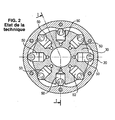
- the cam 20 is fixed by bolting between the two housings 10a and 10b, and the shaft 40, carried by the housing 10b, itself carries the block -cylinders 30.
- the pistons are stapled in the cylinders and are thus held in their housing when the cylinder block is inserted into the cam.
- the distributor 60 is held in place in the housing 10a by angular positioning means.
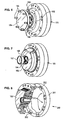
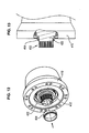
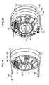
- FIG. figure 3a comprising the basic elements of the motor, namely cam 20, cylinder block 30, pistons 50 and distributor 60, in a housing 10a, also called cover, which constitutes a half-casing for the final motor.
- a subset constituting an incomplete motor is intended to be inserted into the kinematic chain of a user by engagement on a shaft and / or on a complementary housing element 10b that can contain a bearing.
- this subassembly comprises rotating elements and fixed elements (for example respectively a cylinder block and a distributor on the one hand, and a cam on the other hand).
- rotating elements and fixed elements for example respectively a cylinder block and a distributor on the one hand, and a cam on the other hand.
- rotating elements and complementary fixed elements for example respectively a shaft on the one hand and a housing element comprising a bearing on the other hand.
- Such a set is generally referred to as a hydrobase by the Applicant.
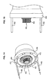
- the hydrobase Before fixing the hydrobase to a shaft and a half-casing which may or may not contain a bearing, it can not be maintained in the mounted state as illustrated in FIG. figure 3a . In reality, it comes in the form of a collection of unrelated pieces, as in figure 3b .
- the cam 20 is not connected to the lid 10a, and the cylinder block 30 is not held in place.
- a main object of the present invention is to improve the means known in the state of the art to facilitate in particular the engagement of such subsets on a shaft or bearing.
- Another object of the invention is to provide a hydrobase in assembled and sealed form, prior to its mounting on a subassembly comprising a shaft and a housing that can contain a bearing, thus allowing its transport without damage or pollution, and with prepositioned elements according to the arrangement chosen by the manufacturer.
- the present invention applies in particular to the case of implantation of a motor having a fixed shaft relative to the frame of the machine and a rotary housing, for example integral with a wheel.
- subassembly intended to form a hydraulic motor after assembly on an assembly comprising a shaft
- subassembly comprises a cover forming a housing element, a cam multilobe, a cylinder block placed opposite the cam, pistons guided to radial sliding in respective cylinders of the cylinder block and bearing on the lobes of the cam and a distributor for successively applying a fluid under pressure on said pistons, characterized in that it comprises means for temporarily fixing the cylinder block on the lid and means for accessing a dispenser element, through the cover, to allow, during installation, the angular orientation of the this element relative to the shaft, then its attachment to the shaft.
- the subassembly or hydrobase comprises means ensuring a pre-positioning angular and / or a fixing of the cam on the cover, for example by means of pins or screws.
- the present invention also relates to a method of assembling the subassembly or hydrobase according to the present invention, to form a hydraulic motor.
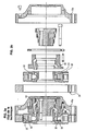
- the subassembly or hydrobase essentially comprises a cover housing element 100, a cam 200, a cylinder block 300 and a distributor 600.
- Each of these elements cover 100, cam 200, cylinder block 300 and distributor 600 may be the subject of many embodiments known in themselves to those skilled in the art corresponding to conventional hydraulic motors and hydrobases, piston engines radial and multilobe cams, also called high torque and low speed motors.
- hydrobase according to the present invention is centered on an axis of rotation O-O.
- the cover 100 constitutes a tight wall transverse to the O-O axis which covers a complete lateral side of the hydrobase. Its contour is preferably circular.
- the cam 200 is preferably formed of a ring 201 adjacent to the axially inner face of the cover 100 at the radially outermost peripheral zone of the cover 100.
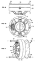
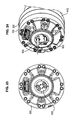
- the cam 200 On its radially inner surface, the cam 200 has, as can be seen for example on the figure 8 , a series of regular lobes 210 equi-distributed around the axis OO. Each of the lobes 210 generally has a sinusoidal type appearance.
- the cam 200 is connected to the cover 100. It is also attached to the rotating hub of the wheel of the machine that carries the rim.
- the cylinder block 300 is placed inside the ring 201 constituting the cam 200. It defines a plurality of cylinders 302 oriented radially with respect to the axis OO and opening on the outer peripheral face of the cylinder block 300 opposite the cam 200.
- a piston 500 is mounted to slide radially respectively in each of the cylinders 302. It bears on the radially inner surface of the cam 200.
- the cylinder block 300 has a central bore through which the cylinder block 300 is engaged on the end of the shaft of the machine to be equipped. Furthermore, this bore has a series of complementary longitudinal grooves splines 402 provided on the end of the shaft to provide angular indexing of the cylinder block 300 on the shaft, once the installed hydrobase.
- the distributor 600 is designed to apply in a controlled manner a fluid under pressure successively to each of the pistons 500, more precisely in the radially inner chamber of the cylinders 302 adjacent the pistons, so that the successive support of the pistons 500 on the lobes of the piston.
- cam 200 causes the relative rotation of the cylinder block 300 and the elements which are connected to it relative to the lid 100, when used on an equipped machine.
- the distributor 600 is formed of two parts: a central part 610 or "against-ice” intended to be placed opposite the end of the shaft and to be fixed thereto and an outer part 620 or “ice “placed around the central piece 610, linked to rotation with the cover 100 by any appropriate means, for example a finger or a locking pin to allow longitudinal sliding between the outer part 620 and the cover 100.
- the indexing means provided between the cover 100 and the part 620 may be formed of a mechanism such as an Oldham seal ensuring the transmission without play of a rotational movement between the cover 100 and the part 620 keeping their axes parallel but not necessarily concentric.
- a mechanism may be formed of a washer perpendicular to the axes of rotation comprising radial oblong slots which respectively receive pins integral with the cover 100 and pins integral with the outer part 620. This means allows a limited sliding along the directions perpendicular to the axis of the motor, while ensuring a precise angular setting.
- the outer part 620 has a transverse face 622 contiguous to a complementary face of the cylinder block.
- the central piece 610 has a series of channels having longitudinal sections 611, 612, 613 which open into respectively complementary channels 460, 462, 464 formed in the shaft 400 to provide the functions of supply and drain and cross sections. 614, 615 which open on the radially outer face of this central piece 610 at peripheral annular grooves, facing the outer part 620.
- the latter has channels with transverse sections which open opposite annular grooves related to the transverse sections 614, 615 of the central piece 610 and longitudinal sections which open opposite the supply ports formed in the piston chambers of the cylinder block 300.
- the channel 460 represents a supply channel of the distributor 600
- the channel 462 represents a channel carrying the return fluid of the distributor
- the channel 464 represents a drain channel which ensures the return of the leaks.
- the cylinder block 300 is rotatably connected to the shaft of the machine to be equipped and is rotatably fixed relative to the central part of the distributor 600.
- the shaft is of course not part of the hydrobase, and was not represented on the Figures 4 and 5 only for a better understanding of the hydraulic interface between the hydrobase and the rest of the machine.
- the feeding of the plunging chambers of the pistons by a fluid passing through channels formed in the shaft and the distributor ensure the rotational drive of the cam 200 relative to the cylinder block 300 and forming the cover 100, of the workpiece External distributor 620 and all the items related to them.
- the section of the longitudinal sections of the channels formed in the outer part 620 of the distributor evolves along the length of these sections, to generate, during the pressurization of the fluid, a force that forces the external part 620 to bear axially against the face facing the cylinder block 300 to ensure a relative seal at this level and prevent fluid leakage.
- the biasing of the outer part or ice 620 against the opposite side of the cylinder block 300 may be reinforced by springs 630. Such an arrangement improves the operation of the engine during the first moments after the application of the hydraulic pressure .
- the sealing at the level of the communication between the channels of the two parts, central 610 and external 620, of the distributor, is provided by seals or any equivalent means, for example segments made of cast iron or plastic.
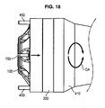
- the hydrobase comprises means 150 of provisional fixing of the cylinder block 300 on the cover 100, as well as access means 180, through the cover 100, to an element of the distributor 600 in order to allow the angular orientation of this element during the installation with respect to the tree that receives the hydrobase.
- such temporary fixing means of the cylinder block 300 on the cover 100 are formed for example of two screws or bolts 152, 154 engaged in diametrically opposed holes formed in the cover 100 opposite two respectively associated holes formed in the cylinder block 300.
- the means 180 allowing access to the distributor 600 through the cover 100 may be formed of different embodiments. They are preferably formed of an opening 182 formed in the center of the cover 100 and passing therethrough, associated with a closure flap 184 fixed on the cover 100 by any suitable removable means.
- the fastening means of the closure flap 184 are formed of a plurality of screws 186 equi-distributed in holes formed in the flap 184 and cooperating with complementary threaded holes formed on the cover 100.
- the closure flap 184 is fixed using an elastic ring 187 circlip type (TM) or any equivalent means.
- TM circlip type
- the presence of access means to the distributor 600 through the cover 100 angularly directs the distributor 600 to align it correctly with respect to supply channels and / or drains from the shaft.
- the hydrobase according to the present invention is further provided with plugs making it possible to seal all the bores made in the cover 100, in particular those intended to receive fastening means 152, 154.
- the bores mentioned above may serve as purge orifices for subsequent maintenance.
- the hydrobase is closed, before its installation on the associated shaft, by a plate 190 located on the face of the cam 200 opposite the cover 100.
- This plate 190 is fixed using any appropriate means for example using a plurality of bolts 192 and nuts 194 complementary.
- Such a plate 190 can also be the subject of many embodiments. It is preferably a simple flat disk of the same external diameter as the cam 200.
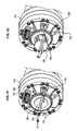
- the hydrobase before being assembled at the receiving machine, is presented as on the Figures 9 and 10 in the form of a block pre-assembled by temporary fixing means.
- This block includes all the elements mentioned above, and already positioned relative to each other in their final mode of operation on the receiving machine, with the exception of the angular adjustment of the distributor with respect to the receiving shaft.
- the lid 100 of the hydrobase is for example intended to be secured to the movable rim of a wheel, the aforementioned complementary shaft being in turn fixed relative to the frame of a machine.
- the frame 410 of the machine and more specifically the output shaft 400 which preferably comprises longitudinal grooves 402 can be equipped with any suitable accessory, for example a ring 404 forming a bearing.
- the hydrobase facing the frame preferably it is provided with support rods 450 parallel to the axis OO engaged for example in complementary bores 412 formed in the frame 410 with a spacing corresponding to complementary holes formed in the hydrobase, more precisely through the cam 200 and the outer periphery of the lid 100.
- the hydrobase without its closure plate 190 can be engaged on the rods 450 to facilitate handling by transferring the weight of the hydrobase in part to the rods 450.
- the use of such rods 450 also facilitates the centering of the hydrobase on the axis of the shaft 400.
- the hydrobase is then pushed axially into sliding towards the spline shaft 400.
- the installer proceeds to a relative angular orientation of the hydrobase and the shaft 400 to engage the cylinder block 300 on said flutes 402 of the shaft 400.
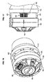
- the temporary support rods 450 can then be removed as shown in FIG. figure 19 and replaced by bolts or fixing screws 110, 112 as shown in the figure 20 .
- the hydrobase can be equipped with a stirrup 156 placed on the outer surface of the lid 100, in diametrical position, and having at its ends eyelets in which are engaged the rods of the screws 152, 154. It is sufficient, once the screw 152, 154, remove the stirrup 156 to easily extract the screws 152, 154. The cylinder block 300 is then disengaged from the cover 100 to allow its relative rotation.
- the access means to the distributor 600 are thus also released. Where appropriate, it may be, as illustrated on Figures 21, 22 , a temporary closure flap 185 released automatically when removing the caliper 156.
- the installer then proceeds as shown on the Figures 23 and 24 , at the angular orientation of the distributor 600 relative to the shaft 400 to align the supply and drain channels of the distributor element with respect to channels in the shaft 400. Then, the The distributor element 600 is fixed on the axial end of the shaft 400 by screws 602, 604.
- the fixing means of the distributor element 600 called against ice on the axial end of the shaft, formed by several screws 602, 604 according to the figure 24 can be replaced by a single bolt, to allow a saving of time of assembly, as well as a saving of place.
- the present invention makes it possible to avoid disassembly / reassembly of the components and saves installation time by improving the quality and reliability of the engine on the machine.
- the hydrobase according to the present invention forms a cartridge that can be used in particular from an end-of-line test bench until assembly on the machine of a user.
- the hydrobase according to the present invention can be equipped with any suitable accessory, for example a brake.
- the present invention allows rapid assembly of the hydrobase on any machine, as well as any disassembly that may be necessary and in complete safety. It guarantees thanks to the simplicity of the means proposed an operational package at the end of the assembly. It also allows easy maintenance.
- the hydrobase according to the present invention can be equipped with a hydraulic brake.
- a hydraulic brake being known in itself, it will not be described in detail later.
Landscapes
- Engineering & Computer Science (AREA)
- Mechanical Engineering (AREA)
- General Engineering & Computer Science (AREA)
- Chemical & Material Sciences (AREA)
- Combustion & Propulsion (AREA)
- Reciprocating Pumps (AREA)
- Hydraulic Motors (AREA)
Claims (15)
- Unterbaugruppe zum Bilden eines Hydraulikmotors nach Montage auf einer Baugruppe mit einer Welle (400), wobei die Unterbaugruppe eine ein Gehäuseelement bildende Abdeckung (100), einen mehrbogigen Nocken (200), einen dem Nocken gegenüberliegenden Zylinderblock (300), Kolben (500), die in den jeweiligen Zylindern des Zylinderblocks (300) durch radiale Gleitführung geführt sind und an den Bogen des Nockens (200) anliegen, und einen Verteiler (600) umfasst, der dazu bestimmt ist, an die Kolben (500) nacheinander ein Druckfluid anzulegen,
dadurch gekennzeichnet, dass sie Mittel (152, 154) zum vorläufigen Befestigen des Zylinderblocks (300) an der Abdeckung (100) und Mittel (185) zum Zugreifen auf ein Element (610) des Verteilers (600) durch die Abdeckung (100) hindurch umfasst, um bei der Anbringung die Winkelausrichtung dieses Elements (610) bezüglich der Welle (400) und anschließend seine Befestigung an der Welle (400) zu ermöglichen. - Unterbaugruppe nach Anspruch 1,
dadurch gekennzeichnet, dass sie Mittel (202) umfasst, die ein winkelgerechtes Vorpositionieren und/oder ein Befestigen des Nockens (202) an der Abdeckung (100) zum Beispiel mit Hilfe von Stiften oder Schrauben gewährleisten. - Unterbaugruppe nach einem der Ansprüche 1 oder 2,
dadurch gekennzeichnet, dass der Verteiler (600) aus zwei Teilen gebildet ist: einem mittleren Teil (610), das dazu bestimmt ist, gegenüber dem Ende der Welle platziert und an dieser befestigt zu werden, und einem um das mittlere Teil herum angeordneten äußeren Teil (620), das zur Drehung mit der Abdeckung (100) durch jedes geeignete Mittel, zum Beispiel einen Zapfen oder einen Klemmstift, verbunden ist. - Unterbaugruppe nach einem der Ansprüche 1 bis 3,
dadurch gekennzeichnet, dass das mittlere Teil (610) eine Reihe Kanäle besitzt, mit Längsabschnitten, die in Kanäle münden, die in der Welle jeweils komplementär ausgebildet sind, um Zulauf- und Ablauffunktionen zu gewährleisten, und mit Querabschnitten, die an der radial außenliegenden Seite des mittleren Teils (610) in Höhe von umlaufenden ringförmigen Nuten gegenüber dem Teil (620) münden, während das äußere Teil (620) Kanäle besitzt mit Querabschnitten, die gegenüber den mit den Querabschnitten des mittleren Teils (610) verbundenen ringförmigen Nuten münden, und mit Längsabschnitten, die gegenüber den Zulauföffnungen münden, die in den Kolbenkammern des Zylinderblocks (300) ausgebildet sind. - Unterbaugruppe nach Anspruch 4,
dadurch gekennzeichnet, dass sich der Querschnitt der in dem äußeren Teil (620) des Verteilers (600) ausgebildeten Längsabschnitte der Kanäle über die Länge dieser Abschnitte verändert, um bei Druckbeaufschlagung des Fluids eine Kraft zu erzeugen, die das äußere Teil (620) in axiale Anlage gegen die gegenüberliegende Seite des Zylinderblocks (300) drängt. - Unterbaugruppe nach einem der Ansprüche 4 oder 5,
dadurch gekennzeichnet, dass sie Federn umfasst, die das äußere Teil (620) des Verteilers (600) gegen den Zylinderblock (300) drängen. - Unterbaugruppe nach einem der Ansprüche 1 bis 6,
dadurch gekennzeichnet, dass die Mittel (180) zur Gewährung des Zugriffs auf den Verteiler (600) durch die Abdeckung (100) hindurch eine Öffnung (182) aufweisen, die in der Mitte der Abdeckung ausgebildet ist, diese durchquert und einer abnehmbaren Verschlussklappe (184) zugeordnet ist. - Unterbaugruppe nach Anspruch 7,
dadurch gekennzeichnet, dass sie Mittel zum Befestigen der Verschlussklappe (184) umfasst, die von einer Vielzahl von Schrauben (186) gebildet sind. - Unterbaugruppe nach Anspruch 7,
dadurch gekennzeichnet, dass sie Mittel zum Befestigen der Verschlussklappe (184) umfasst, die von einem elastischen Ring (187) gebildet sind. - Unterbaugruppe nach einem der Ansprüche 1 bis 9,
dadurch gekennzeichnet, dass sie einen abnehmbaren Bügel (156) umfasst, der Ösen aufweist, in die die Schraubenstifte (152, 154) eingeführt sind, die Mittel zum vorläufigen Befestigen des Zylinderblocks bezüglich der Abdeckung (100) bilden. - Unterbaugruppe nach einem der Ansprüche 1 bis 10,
dadurch gekennzeichnet, dass sie Stopfen zum Verschließen der Bohrungen umfasst, die in der Abdeckung (100) ausgeführt sind, um die Mittel (152, 154) zur Befestigung des Zylinderblocks (300) an der Abdeckung (100) aufzunehmen, wobei die Stopfen nach Entfernen der vorläufigen Befestigungsmittel (152, 154) platziert werden. - Unterbaugruppe nach einem der Ansprüche 1 bis 11,
dadurch gekennzeichnet, dass sie eine Platte (190) umfasst, die an der der Abdekkung (100) entgegengesetzten Seite des Nockens (200) lösbar befestigt ist. - Verfahren zur Montage der Unterbaugruppe gemäß einem der Ansprüche 1 bis 12 auf einer Welle (400),
dadurch gekennzeichnet, dass es die folgenden Schritte umfasst:- Entfernen einer Verschlussplatte (190), die auf der der Abdeckung (100) entgegengesetzten Seite des Nockens (200) angeordnet ist,- Ansetzen der Unterbaugruppe auf das Ende der Welle (400),- Entfernen der vorläufigen Befestigungsmittel (152, 154) des Zylinderblocks (300) bezüglich der Abdeckung (100),- Entfernen der Mittel (185), die Zugang zum Verteiler (600) gewähren,- winkelgerechtes Ausrichten des Verteilers (600) in Bezug auf das Ende der Welle (400), um die in der Welle (400) ausgebildeten Zulauf- und Ablaufleitungen mit im Verteiler (600) ausgebildeten komplementären Leitungen fluchtend anzuordnen,- Befestigen des mittleren Teils (610) des Verteilers (600) bezüglich des Endes der Welle,- Wiederverschließen der in der Abdeckung (100) ausgebildeten Zugangsmittel. - Verfahren nach Anspruch 13,
dadurch gekennzeichnet, dass es den Zwischenschritt des Anordnens von Haltestiften (450) auf dem Gehäuse der Maschine umfasst, um dem Gehäuse der Unterbaugruppe (100) beim Ansetzen auf der Welle (400) als Halterung zu dienen. - Verfahren nach einem der Ansprüche 13 oder 14,
dadurch gekennzeichnet, dass es den zusätzlichen Schritt des Verschließens der Öffnungen, welche die vorläufigen Befestigungsmittel des Zylinderblocks (300) bezüglich der Abdeckung (100) aufnehmen, mit Hilfe von Entleerungsschrauben (122, 124) umfasst.
Applications Claiming Priority (2)
| Application Number | Priority Date | Filing Date | Title |
|---|---|---|---|
| FR1050667A FR2955903B1 (fr) | 2010-02-01 | 2010-02-01 | Sous-ensemble formant hydrobase pour moteurs hydrauliques et procede d'assemblage |
| PCT/EP2011/051262 WO2011092312A1 (fr) | 2010-02-01 | 2011-01-28 | Sous-ensemble formant hydrobase pour moteurs hydrauliques et procede d'assemblage |
Publications (2)
| Publication Number | Publication Date |
|---|---|
| EP2531720A1 EP2531720A1 (de) | 2012-12-12 |
| EP2531720B1 true EP2531720B1 (de) | 2013-12-11 |
Family
ID=43048828
Family Applications (1)
| Application Number | Title | Priority Date | Filing Date |
|---|---|---|---|
| EP11701822.6A Active EP2531720B1 (de) | 2010-02-01 | 2011-01-28 | Hydrobase unteranordnung für hydraulische motoren, und montageverfahren für diese unteranordnung. |
Country Status (5)
| Country | Link |
|---|---|
| US (1) | US9284942B2 (de) |
| EP (1) | EP2531720B1 (de) |
| CN (1) | CN102884308B (de) |
| FR (1) | FR2955903B1 (de) |
| WO (1) | WO2011092312A1 (de) |
Cited By (1)
| Publication number | Priority date | Publication date | Assignee | Title |
|---|---|---|---|---|
| DE102015222291B4 (de) | 2015-11-12 | 2019-09-12 | Robert Bosch Gmbh | Radialkolbenmaschine mit verdrehgesicherten Bremsmitteln |
Families Citing this family (12)
| Publication number | Priority date | Publication date | Assignee | Title |
|---|---|---|---|---|
| FR3010741B1 (fr) * | 2013-09-18 | 2015-09-18 | Poclain Hydraulics Ind | Cartouche formant un moteur ou une pompe hydraulique preassemble a pistons radiaux |
| FR3019594B1 (fr) | 2014-04-02 | 2016-04-08 | Poclain Hydraulics Ind | Section additionnelle de poussee |
| FR3026791B1 (fr) * | 2014-10-03 | 2019-04-19 | Poclain Hydraulics Industrie | Mecanisme hydraulique muni de moyens de guidage en translation des pistons |
| FR3052819B1 (fr) | 2016-06-16 | 2019-07-19 | Poclain Hydraulics Industrie | Piston a galet pour machine hydraulique, venu de matiere avec element de centrage forme pour limiter les frottements avec un galet |
| FR3056662B1 (fr) * | 2016-09-23 | 2018-11-23 | Poclain Hydraulics Ind | Systeme de freinage ameliore pour machine hydraulique |
| NL2019045B1 (en) * | 2017-06-09 | 2018-12-17 | Delft Offshore Turbine B V | Wind turbine generator with hydraulic pump |
| DE112019002880T5 (de) | 2018-06-07 | 2021-05-06 | Parker-Hannifin Corporation | Hydraulikmotor-Unterbaugruppenbausatz mit Träger |
| FR3084411B1 (fr) | 2018-07-25 | 2021-06-18 | Poclain Hydraulics Ind | Machine hydraulique |
| WO2020021019A1 (fr) | 2018-07-25 | 2020-01-30 | Poclain Hydraulics Industrie | Machine hydraulique |
| FR3090755B1 (fr) | 2018-12-21 | 2021-01-08 | Poclain Hydraulics Ind | Texturation de surfaces |
| FR3094425B1 (fr) | 2019-03-27 | 2021-04-23 | Poclain Hydraulics Ind | Machine hydraulique comportant un palier perfectionné |
| US12320412B2 (en) | 2022-09-07 | 2025-06-03 | Regents Of The University Of Minnesota | Axial piston variable displacement hydraulic devices, such as hydraulic motors, and methods of operating same |
Family Cites Families (10)
| Publication number | Priority date | Publication date | Assignee | Title |
|---|---|---|---|---|
| US3760691A (en) * | 1971-12-17 | 1973-09-25 | Deere & Co | Step variable displacement hydraulic motor |
| GB2044348B (en) * | 1979-03-01 | 1983-01-06 | Poclain Hydralics | Fluid mechanism with axially movable valve-seat |
| US4381700A (en) * | 1980-09-02 | 1983-05-03 | Lenz Leonard L | Stepless infinite variable speed motor |
| SE456517B (sv) * | 1982-09-08 | 1988-10-10 | Hegglund & Soner Ab | Hydraulisk radialkolvmotor |
| FR2651836B1 (fr) * | 1989-09-14 | 1994-06-10 | Poclain Hydraulics Sa | Mecanisme, moteur ou pompe, a pistons supportant des rouleaux d'appui desdits pistons sur une came. |
| US6036611A (en) * | 1997-07-07 | 2000-03-14 | Poclain Hydraulics Industrie | Drive mechanism for driving displacement members disposed in tandem |
| GB0026818D0 (en) * | 2000-11-02 | 2000-12-20 | Rotech Holdings Ltd | Fluid machine |
| FR2834012B1 (fr) * | 2001-12-24 | 2004-03-19 | Poclain Hydraulics Ind | Moteur hydraulique a pistons radiaux |
| CN100485185C (zh) * | 2007-09-11 | 2009-05-06 | 宁波欧易液压有限公司 | 轴配油连杆式液压马达 |
| DE102008017535B3 (de) * | 2008-04-03 | 2009-08-27 | Hofer Mechatronik Gmbh | Radialkolbenpumpe |
-
2010
- 2010-02-01 FR FR1050667A patent/FR2955903B1/fr not_active Expired - Fee Related
-
2011
- 2011-01-28 WO PCT/EP2011/051262 patent/WO2011092312A1/fr not_active Ceased
- 2011-01-28 US US13/576,311 patent/US9284942B2/en active Active
- 2011-01-28 EP EP11701822.6A patent/EP2531720B1/de active Active
- 2011-01-28 CN CN201180016411.4A patent/CN102884308B/zh not_active Expired - Fee Related
Cited By (1)
| Publication number | Priority date | Publication date | Assignee | Title |
|---|---|---|---|---|
| DE102015222291B4 (de) | 2015-11-12 | 2019-09-12 | Robert Bosch Gmbh | Radialkolbenmaschine mit verdrehgesicherten Bremsmitteln |
Also Published As
| Publication number | Publication date |
|---|---|
| CN102884308B (zh) | 2015-07-01 |
| FR2955903A1 (fr) | 2011-08-05 |
| WO2011092312A1 (fr) | 2011-08-04 |
| US9284942B2 (en) | 2016-03-15 |
| US20120297972A1 (en) | 2012-11-29 |
| CN102884308A (zh) | 2013-01-16 |
| EP2531720A1 (de) | 2012-12-12 |
| FR2955903B1 (fr) | 2012-03-16 |
Similar Documents
| Publication | Publication Date | Title |
|---|---|---|
| EP2531720B1 (de) | Hydrobase unteranordnung für hydraulische motoren, und montageverfahren für diese unteranordnung. | |
| CA2635635C (fr) | Dispositif de retenue axiale d'aubes montees sur un disque de rotor de turbomachine | |
| EP2990678B1 (de) | Kupplungsvorrichtung für kraftfahrzeug | |
| FR2943312A1 (fr) | Helice non carenee a pales a calage variable pour une turbomachine | |
| US20170260884A1 (en) | Cam phaser | |
| WO2015110751A1 (fr) | Disque de rotor a dispositif de prélèvement d'air centripète, compresseur comportant ledit disque et turbomachine avec un tel compresseur | |
| FR2748538A1 (fr) | Appareil d'accouplement hydrocinetique a piece d'entrainement de languettes, notamment pour vehicule automobile | |
| FR2748539A1 (fr) | Appareil d'accouplement hydrocinetique a piece d'entrainement de languettes, notamment pour vehicule automobile | |
| WO1996021812A9 (fr) | Procede de fabrication d'un volant amortisseur notamment pour vehicules automobiles | |
| WO2018073211A1 (fr) | Système d'embrayage, et procédé de montage d'un système d'embrayage | |
| EP1688634B1 (de) | Befestigungsvorrichtung eines Lagers auf einem Getriebeelement | |
| CA2747983A1 (fr) | Dispositif de fixation d'aubes a attache marteau, disque de compresseur, compresseur et turbomachine associes | |
| FR3060680B1 (fr) | Module de transmission de couple destine a equiper une transmission de vehicule automobile | |
| EP3756994A1 (de) | Vorschubpropeller, der mit auswechselbaren schraubenblättern ausgestattet ist, und montageverfahren für auswechselbare schraubenblätter auf einem vorschubpropeller | |
| FR3140123A1 (fr) | Modularite d’une turbomachine d’aeronef par un dispositif de blocage axial et en rotation, procede de montage correspondant | |
| EP3406901B1 (de) | Hydraulisches gerät, das einen verbesserten verteiler umfasst | |
| FR3001272A3 (fr) | "differentiel de transmission" | |
| FR3086714A1 (fr) | Dispositif de transmission pour vehicule hybride | |
| WO2006136756A2 (fr) | Dispositif d'entrainement d'un volant moteur par un banc d'essais | |
| FR2748540A1 (fr) | Appareil d'accouplement hydrocinetique a piece d'entrainement de languettes, notamment pour vehicule automobile | |
| FR3086712A1 (fr) | Dispositif de transmission pour vehicule hybride | |
| FR3100261A1 (fr) | Kit pour l’élaboration d’un ensemble autoportant de serrure électronique | |
| FR3083278A1 (fr) | Porte-disque assemble et mecanisme d'embrayage humide comprenant ce porte-disque assemble | |
| FR3083202A1 (fr) | Outil d'assemblage pour un systeme de transmission et procede d'assemblage d'un tel systeme de transmission | |
| FR3041047A1 (fr) | Couvercle avec doigt d'arret d'ecrou |
Legal Events
| Date | Code | Title | Description |
|---|---|---|---|
| PUAI | Public reference made under article 153(3) epc to a published international application that has entered the european phase |
Free format text: ORIGINAL CODE: 0009012 |
|
| 17P | Request for examination filed |
Effective date: 20120830 |
|
| AK | Designated contracting states |
Kind code of ref document: A1 Designated state(s): AL AT BE BG CH CY CZ DE DK EE ES FI FR GB GR HR HU IE IS IT LI LT LU LV MC MK MT NL NO PL PT RO RS SE SI SK SM TR |
|
| DAX | Request for extension of the european patent (deleted) | ||
| GRAP | Despatch of communication of intention to grant a patent |
Free format text: ORIGINAL CODE: EPIDOSNIGR1 |
|
| INTG | Intention to grant announced |
Effective date: 20130627 |
|
| GRAS | Grant fee paid |
Free format text: ORIGINAL CODE: EPIDOSNIGR3 |
|
| GRAA | (expected) grant |
Free format text: ORIGINAL CODE: 0009210 |
|
| AK | Designated contracting states |
Kind code of ref document: B1 Designated state(s): AL AT BE BG CH CY CZ DE DK EE ES FI FR GB GR HR HU IE IS IT LI LT LU LV MC MK MT NL NO PL PT RO RS SE SI SK SM TR |
|
| REG | Reference to a national code |
Ref country code: GB Ref legal event code: FG4D Free format text: NOT ENGLISH |
|
| REG | Reference to a national code |
Ref country code: CH Ref legal event code: EP |
|
| REG | Reference to a national code |
Ref country code: AT Ref legal event code: REF Ref document number: 644750 Country of ref document: AT Kind code of ref document: T Effective date: 20140115 |
|
| REG | Reference to a national code |
Ref country code: IE Ref legal event code: FG4D Free format text: LANGUAGE OF EP DOCUMENT: FRENCH |
|
| REG | Reference to a national code |
Ref country code: DE Ref legal event code: R096 Ref document number: 602011004153 Country of ref document: DE Effective date: 20140206 |
|
| REG | Reference to a national code |
Ref country code: NL Ref legal event code: VDEP Effective date: 20131211 |
|
| REG | Reference to a national code |
Ref country code: AT Ref legal event code: MK05 Ref document number: 644750 Country of ref document: AT Kind code of ref document: T Effective date: 20131211 |
|
| PG25 | Lapsed in a contracting state [announced via postgrant information from national office to epo] |
Ref country code: LT Free format text: LAPSE BECAUSE OF FAILURE TO SUBMIT A TRANSLATION OF THE DESCRIPTION OR TO PAY THE FEE WITHIN THE PRESCRIBED TIME-LIMIT Effective date: 20131211 Ref country code: HR Free format text: LAPSE BECAUSE OF FAILURE TO SUBMIT A TRANSLATION OF THE DESCRIPTION OR TO PAY THE FEE WITHIN THE PRESCRIBED TIME-LIMIT Effective date: 20131211 Ref country code: SE Free format text: LAPSE BECAUSE OF FAILURE TO SUBMIT A TRANSLATION OF THE DESCRIPTION OR TO PAY THE FEE WITHIN THE PRESCRIBED TIME-LIMIT Effective date: 20131211 Ref country code: FI Free format text: LAPSE BECAUSE OF FAILURE TO SUBMIT A TRANSLATION OF THE DESCRIPTION OR TO PAY THE FEE WITHIN THE PRESCRIBED TIME-LIMIT Effective date: 20131211 Ref country code: NL Free format text: LAPSE BECAUSE OF FAILURE TO SUBMIT A TRANSLATION OF THE DESCRIPTION OR TO PAY THE FEE WITHIN THE PRESCRIBED TIME-LIMIT Effective date: 20131211 Ref country code: NO Free format text: LAPSE BECAUSE OF FAILURE TO SUBMIT A TRANSLATION OF THE DESCRIPTION OR TO PAY THE FEE WITHIN THE PRESCRIBED TIME-LIMIT Effective date: 20140311 |
|
| REG | Reference to a national code |
Ref country code: LT Ref legal event code: MG4D |
|
| PG25 | Lapsed in a contracting state [announced via postgrant information from national office to epo] |
Ref country code: LV Free format text: LAPSE BECAUSE OF FAILURE TO SUBMIT A TRANSLATION OF THE DESCRIPTION OR TO PAY THE FEE WITHIN THE PRESCRIBED TIME-LIMIT Effective date: 20131211 Ref country code: CY Free format text: LAPSE BECAUSE OF FAILURE TO SUBMIT A TRANSLATION OF THE DESCRIPTION OR TO PAY THE FEE WITHIN THE PRESCRIBED TIME-LIMIT Effective date: 20131211 Ref country code: RS Free format text: LAPSE BECAUSE OF FAILURE TO SUBMIT A TRANSLATION OF THE DESCRIPTION OR TO PAY THE FEE WITHIN THE PRESCRIBED TIME-LIMIT Effective date: 20131211 Ref country code: AT Free format text: LAPSE BECAUSE OF FAILURE TO SUBMIT A TRANSLATION OF THE DESCRIPTION OR TO PAY THE FEE WITHIN THE PRESCRIBED TIME-LIMIT Effective date: 20131211 |
|
| BERE | Be: lapsed |
Owner name: POCLAIN HYDRAULICS INDUSTRIE Effective date: 20140131 |
|
| PG25 | Lapsed in a contracting state [announced via postgrant information from national office to epo] |
Ref country code: EE Free format text: LAPSE BECAUSE OF FAILURE TO SUBMIT A TRANSLATION OF THE DESCRIPTION OR TO PAY THE FEE WITHIN THE PRESCRIBED TIME-LIMIT Effective date: 20131211 Ref country code: IS Free format text: LAPSE BECAUSE OF FAILURE TO SUBMIT A TRANSLATION OF THE DESCRIPTION OR TO PAY THE FEE WITHIN THE PRESCRIBED TIME-LIMIT Effective date: 20140411 |
|
| PG25 | Lapsed in a contracting state [announced via postgrant information from national office to epo] |
Ref country code: LU Free format text: LAPSE BECAUSE OF FAILURE TO SUBMIT A TRANSLATION OF THE DESCRIPTION OR TO PAY THE FEE WITHIN THE PRESCRIBED TIME-LIMIT Effective date: 20140128 Ref country code: CZ Free format text: LAPSE BECAUSE OF FAILURE TO SUBMIT A TRANSLATION OF THE DESCRIPTION OR TO PAY THE FEE WITHIN THE PRESCRIBED TIME-LIMIT Effective date: 20131211 Ref country code: SK Free format text: LAPSE BECAUSE OF FAILURE TO SUBMIT A TRANSLATION OF THE DESCRIPTION OR TO PAY THE FEE WITHIN THE PRESCRIBED TIME-LIMIT Effective date: 20131211 Ref country code: ES Free format text: LAPSE BECAUSE OF FAILURE TO SUBMIT A TRANSLATION OF THE DESCRIPTION OR TO PAY THE FEE WITHIN THE PRESCRIBED TIME-LIMIT Effective date: 20131211 Ref country code: RO Free format text: LAPSE BECAUSE OF FAILURE TO SUBMIT A TRANSLATION OF THE DESCRIPTION OR TO PAY THE FEE WITHIN THE PRESCRIBED TIME-LIMIT Effective date: 20131211 Ref country code: PL Free format text: LAPSE BECAUSE OF FAILURE TO SUBMIT A TRANSLATION OF THE DESCRIPTION OR TO PAY THE FEE WITHIN THE PRESCRIBED TIME-LIMIT Effective date: 20131211 Ref country code: PT Free format text: LAPSE BECAUSE OF FAILURE TO SUBMIT A TRANSLATION OF THE DESCRIPTION OR TO PAY THE FEE WITHIN THE PRESCRIBED TIME-LIMIT Effective date: 20140411 |
|
| REG | Reference to a national code |
Ref country code: CH Ref legal event code: PL |
|
| REG | Reference to a national code |
Ref country code: DE Ref legal event code: R097 Ref document number: 602011004153 Country of ref document: DE |
|
| PG25 | Lapsed in a contracting state [announced via postgrant information from national office to epo] |
Ref country code: MC Free format text: LAPSE BECAUSE OF FAILURE TO SUBMIT A TRANSLATION OF THE DESCRIPTION OR TO PAY THE FEE WITHIN THE PRESCRIBED TIME-LIMIT Effective date: 20131211 |
|
| PLBE | No opposition filed within time limit |
Free format text: ORIGINAL CODE: 0009261 |
|
| STAA | Information on the status of an ep patent application or granted ep patent |
Free format text: STATUS: NO OPPOSITION FILED WITHIN TIME LIMIT |
|
| PG25 | Lapsed in a contracting state [announced via postgrant information from national office to epo] |
Ref country code: CH Free format text: LAPSE BECAUSE OF NON-PAYMENT OF DUE FEES Effective date: 20140131 Ref country code: LI Free format text: LAPSE BECAUSE OF NON-PAYMENT OF DUE FEES Effective date: 20140131 Ref country code: DK Free format text: LAPSE BECAUSE OF FAILURE TO SUBMIT A TRANSLATION OF THE DESCRIPTION OR TO PAY THE FEE WITHIN THE PRESCRIBED TIME-LIMIT Effective date: 20131211 |
|
| REG | Reference to a national code |
Ref country code: IE Ref legal event code: MM4A |
|
| 26N | No opposition filed |
Effective date: 20140912 |
|
| REG | Reference to a national code |
Ref country code: DE Ref legal event code: R097 Ref document number: 602011004153 Country of ref document: DE Effective date: 20140912 |
|
| PG25 | Lapsed in a contracting state [announced via postgrant information from national office to epo] |
Ref country code: BE Free format text: LAPSE BECAUSE OF NON-PAYMENT OF DUE FEES Effective date: 20140131 Ref country code: IE Free format text: LAPSE BECAUSE OF NON-PAYMENT OF DUE FEES Effective date: 20140128 |
|
| PG25 | Lapsed in a contracting state [announced via postgrant information from national office to epo] |
Ref country code: SI Free format text: LAPSE BECAUSE OF FAILURE TO SUBMIT A TRANSLATION OF THE DESCRIPTION OR TO PAY THE FEE WITHIN THE PRESCRIBED TIME-LIMIT Effective date: 20131211 |
|
| REG | Reference to a national code |
Ref country code: FR Ref legal event code: PLFP Year of fee payment: 6 |
|
| PG25 | Lapsed in a contracting state [announced via postgrant information from national office to epo] |
Ref country code: MT Free format text: LAPSE BECAUSE OF FAILURE TO SUBMIT A TRANSLATION OF THE DESCRIPTION OR TO PAY THE FEE WITHIN THE PRESCRIBED TIME-LIMIT Effective date: 20131211 |
|
| PG25 | Lapsed in a contracting state [announced via postgrant information from national office to epo] |
Ref country code: SM Free format text: LAPSE BECAUSE OF FAILURE TO SUBMIT A TRANSLATION OF THE DESCRIPTION OR TO PAY THE FEE WITHIN THE PRESCRIBED TIME-LIMIT Effective date: 20131211 |
|
| PG25 | Lapsed in a contracting state [announced via postgrant information from national office to epo] |
Ref country code: GR Free format text: LAPSE BECAUSE OF FAILURE TO SUBMIT A TRANSLATION OF THE DESCRIPTION OR TO PAY THE FEE WITHIN THE PRESCRIBED TIME-LIMIT Effective date: 20140312 Ref country code: IT Free format text: LAPSE BECAUSE OF FAILURE TO SUBMIT A TRANSLATION OF THE DESCRIPTION OR TO PAY THE FEE WITHIN THE PRESCRIBED TIME-LIMIT Effective date: 20131211 Ref country code: BG Free format text: LAPSE BECAUSE OF FAILURE TO SUBMIT A TRANSLATION OF THE DESCRIPTION OR TO PAY THE FEE WITHIN THE PRESCRIBED TIME-LIMIT Effective date: 20131211 |
|
| PG25 | Lapsed in a contracting state [announced via postgrant information from national office to epo] |
Ref country code: HU Free format text: LAPSE BECAUSE OF FAILURE TO SUBMIT A TRANSLATION OF THE DESCRIPTION OR TO PAY THE FEE WITHIN THE PRESCRIBED TIME-LIMIT; INVALID AB INITIO Effective date: 20110128 Ref country code: TR Free format text: LAPSE BECAUSE OF FAILURE TO SUBMIT A TRANSLATION OF THE DESCRIPTION OR TO PAY THE FEE WITHIN THE PRESCRIBED TIME-LIMIT Effective date: 20131211 |
|
| REG | Reference to a national code |
Ref country code: FR Ref legal event code: PLFP Year of fee payment: 7 |
|
| REG | Reference to a national code |
Ref country code: FR Ref legal event code: PLFP Year of fee payment: 8 |
|
| PG25 | Lapsed in a contracting state [announced via postgrant information from national office to epo] |
Ref country code: MK Free format text: LAPSE BECAUSE OF FAILURE TO SUBMIT A TRANSLATION OF THE DESCRIPTION OR TO PAY THE FEE WITHIN THE PRESCRIBED TIME-LIMIT Effective date: 20131211 |
|
| PG25 | Lapsed in a contracting state [announced via postgrant information from national office to epo] |
Ref country code: AL Free format text: LAPSE BECAUSE OF FAILURE TO SUBMIT A TRANSLATION OF THE DESCRIPTION OR TO PAY THE FEE WITHIN THE PRESCRIBED TIME-LIMIT Effective date: 20131211 |
|
| PGFP | Annual fee paid to national office [announced via postgrant information from national office to epo] |
Ref country code: GB Payment date: 20230123 Year of fee payment: 13 |
|
| P01 | Opt-out of the competence of the unified patent court (upc) registered |
Effective date: 20230513 |
|
| GBPC | Gb: european patent ceased through non-payment of renewal fee |
Effective date: 20240128 |
|
| PG25 | Lapsed in a contracting state [announced via postgrant information from national office to epo] |
Ref country code: GB Free format text: LAPSE BECAUSE OF NON-PAYMENT OF DUE FEES Effective date: 20240128 |
|
| PG25 | Lapsed in a contracting state [announced via postgrant information from national office to epo] |
Ref country code: GB Free format text: LAPSE BECAUSE OF NON-PAYMENT OF DUE FEES Effective date: 20240128 |
|
| PGFP | Annual fee paid to national office [announced via postgrant information from national office to epo] |
Ref country code: DE Payment date: 20250116 Year of fee payment: 15 |
|
| PGFP | Annual fee paid to national office [announced via postgrant information from national office to epo] |
Ref country code: FR Payment date: 20251212 Year of fee payment: 16 |