EP2531705B1 - Générateur thermoélectrique doté d'un palier précontraint intégré - Google Patents
Générateur thermoélectrique doté d'un palier précontraint intégré Download PDFInfo
- Publication number
- EP2531705B1 EP2531705B1 EP10795372.1A EP10795372A EP2531705B1 EP 2531705 B1 EP2531705 B1 EP 2531705B1 EP 10795372 A EP10795372 A EP 10795372A EP 2531705 B1 EP2531705 B1 EP 2531705B1
- Authority
- EP
- European Patent Office
- Prior art keywords
- pipes
- tubes
- pipe
- heat sink
- heat source
- Prior art date
- Legal status (The legal status is an assumption and is not a legal conclusion. Google has not performed a legal analysis and makes no representation as to the accuracy of the status listed.)
- Not-in-force
Links
Images
Classifications
-
- F—MECHANICAL ENGINEERING; LIGHTING; HEATING; WEAPONS; BLASTING
- F01—MACHINES OR ENGINES IN GENERAL; ENGINE PLANTS IN GENERAL; STEAM ENGINES
- F01N—GAS-FLOW SILENCERS OR EXHAUST APPARATUS FOR MACHINES OR ENGINES IN GENERAL; GAS-FLOW SILENCERS OR EXHAUST APPARATUS FOR INTERNAL COMBUSTION ENGINES
- F01N5/00—Exhaust or silencing apparatus combined or associated with devices profiting from exhaust energy
- F01N5/02—Exhaust or silencing apparatus combined or associated with devices profiting from exhaust energy the devices using heat
- F01N5/025—Exhaust or silencing apparatus combined or associated with devices profiting from exhaust energy the devices using heat the device being thermoelectric generators
-
- H—ELECTRICITY
- H10—SEMICONDUCTOR DEVICES; ELECTRIC SOLID-STATE DEVICES NOT OTHERWISE PROVIDED FOR
- H10N—ELECTRIC SOLID-STATE DEVICES NOT OTHERWISE PROVIDED FOR
- H10N10/00—Thermoelectric devices comprising a junction of dissimilar materials, i.e. devices exhibiting Seebeck or Peltier effects
- H10N10/01—Manufacture or treatment
-
- H—ELECTRICITY
- H10—SEMICONDUCTOR DEVICES; ELECTRIC SOLID-STATE DEVICES NOT OTHERWISE PROVIDED FOR
- H10N—ELECTRIC SOLID-STATE DEVICES NOT OTHERWISE PROVIDED FOR
- H10N10/00—Thermoelectric devices comprising a junction of dissimilar materials, i.e. devices exhibiting Seebeck or Peltier effects
- H10N10/10—Thermoelectric devices comprising a junction of dissimilar materials, i.e. devices exhibiting Seebeck or Peltier effects operating with only the Peltier or Seebeck effects
- H10N10/13—Thermoelectric devices comprising a junction of dissimilar materials, i.e. devices exhibiting Seebeck or Peltier effects operating with only the Peltier or Seebeck effects characterised by the heat-exchanging means at the junction
-
- F—MECHANICAL ENGINEERING; LIGHTING; HEATING; WEAPONS; BLASTING
- F28—HEAT EXCHANGE IN GENERAL
- F28F—DETAILS OF HEAT-EXCHANGE AND HEAT-TRANSFER APPARATUS, OF GENERAL APPLICATION
- F28F2265/00—Safety or protection arrangements; Arrangements for preventing malfunction
- F28F2265/26—Safety or protection arrangements; Arrangements for preventing malfunction for allowing differential expansion between elements
-
- Y—GENERAL TAGGING OF NEW TECHNOLOGICAL DEVELOPMENTS; GENERAL TAGGING OF CROSS-SECTIONAL TECHNOLOGIES SPANNING OVER SEVERAL SECTIONS OF THE IPC; TECHNICAL SUBJECTS COVERED BY FORMER USPC CROSS-REFERENCE ART COLLECTIONS [XRACs] AND DIGESTS
- Y02—TECHNOLOGIES OR APPLICATIONS FOR MITIGATION OR ADAPTATION AGAINST CLIMATE CHANGE
- Y02T—CLIMATE CHANGE MITIGATION TECHNOLOGIES RELATED TO TRANSPORTATION
- Y02T10/00—Road transport of goods or passengers
- Y02T10/10—Internal combustion engine [ICE] based vehicles
- Y02T10/12—Improving ICE efficiencies
Definitions
- thermoelectric generators To use the heat energy of, for example, internal combustion engines, it is known to use thermoelectric generators.
- the document relates DE 10 2006 057 662 A1 a vehicle with a thermoelectric generator in which heat sources and heat sinks are arranged in their longitudinal course perpendicular to each other in the stack, wherein there are thermoelectric elements between the individual heat sources and heat sinks.
- Heat source and heat sink are provided by a plurality of heat conductive tubes, wherein the thermoelectric generator elements are integrated between the tubes.
- thermoelectric generators with radially acting spring elements therefore have a structure in which initially the heat sink, heat source and the generator elements are integrated with each other and Only from the outside spring elements act on the integrated structure, supported by an outer circumferential holder.
- the DE 10 2005 036 768 A1 discloses a heater having a thermoelectric device with a plurality of thermocouple legs.
- US5,892,656 discloses a thermoelectric generator having at least one hot side heat exchanger and at least one cold side heat exchanger and at least one thermoelectric module having thermoelectric elements installed in an injection-molded egg grid. The thermoelectric modules are held in close contact with the hot side heat exchanger and the cold side heat exchanger by spring force.
- Thermoelectric generators according to the prior art are thus limited in their degree of integration to single-layered concentric structures.
- the known spring structure is not suitable for high temperature differences or temperature changes, since many of the generator elements, especially the inner generator elements, lose their thermal coupling with strong temperature differences on heat-related column, without this can be compensated by spring action, since usually arranged spring elements provide a high thermal resistance.
- thermoelectric generator allows any degree of integration, without internal generator elements would be acted upon with an insufficient spring force.
- the arrangement according to the invention makes it possible, in particular, to preload the generator elements and associated tubes (which serve as a collection source or heat sink), which are of the Location of the respective generator element in the thermoelectric generator is independent.
- spring element assemblies according to the invention allow only the outer elements to be subjected to a spring force, with further inner generator elements not receiving sufficient spring force to maintain contact with the heat sink and the heat source in the event of temperature changes or even vibrations.
- the inventive structure allows any number of tubes and generator elements can be combined to form a compact generator, which automatically the specific surface, the integration density or the generator power based on the generator volume can be significantly increased.
- the device according to the invention can be provided with simple means, in particular without spring elements and support structures concentrated around the actual generator, which form the abutment for the entire spring force.
- the arrangement according to the invention allows a space-saving integration of the elements that press the generator elements on the respective tubes in a wide temperature range. In particular, this reduces the circumference of the generator while maintaining power (or increased power) over the prior art.
- the concept underlying the invention is to provide the spring elements not around the outer tubes, but integrated in the generator structure. While the prior art merely provides for external force and spring force only for the outer tubes, the invention provides for providing a biasing bearing device which biases the tubes themselves to each other and thereby the intermediate generator element by means of the tubes compresses.
- the spring force generating element is in this case provided at least partly between the tubes, provided in the tubes, provided by the tubes themselves, or is provided, for example as a subcomponent, on the end face of the tubes.
- the preload bearing element exerts the force directly on the tubes, either by arranging spring elements in the tubes themselves, on the front sides of the tubes (as a subcomponent) or by suitable storage of the tubes to their spring force or the spring force of a front-side bracket immediately to act on the pipes.
- the tube walls are used themselves, optionally alternatively or in combination with a front-side support which provides a bottom plate, or by spring elements which are located within the tubes and thus provide no to be bridged thermal resistance between a generator element and a tube outside.
- the arrangement according to the invention allows equally not only tubes lying in the outermost layer to be subjected to a spring force.
- the preload bearing device is not provided exclusively on the outside of the thermoelectric generator but also within the generator (ie within the tubes or at the end faces), together with force distributing elements or spring elements provided by the tube walls themselves, directly around the spring force on internal, ie to distribute all components.
- the device according to the invention generates a predetermined spring force which is below a defined maximum spring force, substantially independent of the operating temperature interval.
- the thermoelectric generator according to the invention comprises a housing in which at least one heat source tube, at least one heat sink tube, and at least one generator element is arranged, the generator element being disposed between the dissimilar tubes (i.e., between a heat source tube and a heat sink tube).
- the preload bearing device according to the invention provides a spring force acting between the tubes, i. H. which serves to bias the tubes to each other.
- the spring force acts directly on the pipes themselves and is not transmitted from the outside pipe to pipe inside, such a transmission would drop the amount of spring force from outside to inside clearly.
- the biasing bearing device acts directly on the tubes themselves, regardless of their distance from the center of the thermoelectric generator.
- the bias bearing device thus compresses generator elements by exerting pressure on tubes that directly adjoin the generator element.
- the biasing bearing device is further distributed across the cross section of the generator and exerts immediate force on the tubes by the biasing bearing device is either located directly on the end faces of the tubes or provided by the tube walls themselves or produced by spring elements present in the tubes becomes.
- Between preload bearing device and pipes thus results in a direct mechanical contact, in particular by (partial) identity between preload bearing device and pipes, by frictional connection between preload bearing device and pipes or by positive engagement between preload bearing device and pipe. This applies to all tubes of the thermoelectric generator, in particular for the inner tubes.
- the bias bearing device serves as an inner surface of the housing as an abutment.
- the inside of the housing thus provides a support for the preload bearing device, wherein due to the adjustment of the spring forces, the support is subjected to a counter force of the spring force of the preload bearing device.
- the amount of drag may correspond to the spring force that the bias bearing device applies to the tubes.
- the bias bearing device serves for a storage of the tubes and on the other to generate bias.
- the storage allows a displacement of the tubes with each other to compensate for strong temperature changes movements that result from different thermal expansions.
- the bearing provided by the preload bearing device may also be provided by a sprung, ie prestressed, bearing, allowing compensation of the spring forces acting on the tubes by movement or deformation of the tubes.
- the tubes are clamped between bottom plates.
- the surface of the bottom plates have micro or macrostructures to hold the end faces of the tubes in place. Due to the force with which the bottom plates press on the end faces of the tubes, there is a frictional connection with a defined maximum adhesive force resulting from the material and in particular from the microstructures, together with the contact pressure (ie normal force) with which the Pipes act on the floor slabs.
- a microstructure in particular a roughened metal surface is suitable, for example by brushing or the like.
- the bias bearing device is formed by the bottom plates, in particular by the surfaces of the bottom plates, and by the end faces of the tubes.
- the floor panels themselves can be provided elastically.
- the pipes themselves may be provided elastically, so that the pipe walls themselves provide the spring effect.
- the tubes serve to transmit the spring action over the length of the tubes, so that the tubes are formed with a low elasticity.
- the tubes are substantially rigid and exert a strong spring force even at low deflections.
- This is made possible by providing the bottom plate or the tubes (or both) at least slightly elastic, ie of elastic material and with an elastic structure. Based on the elasticity and the dimensions of the base plate and tube, the maximum adhesive force and the maximum radial force can be accurately provided depending on the bias of the tubes in longitudinal force, from which the frictional or positive connection between the tube and bottom plate yields and slipping allows.
- the distinction between positive locking and traction depends essentially on the consideration of the structures of the bottom plate surfaces. Even mutually rubbing microstructures can be considered as a releasable positive locking when elevations of the microstructures are considered as a form-locking form, which yield due to their elasticity or plasticity.
- the height of the maximum adhesion force and the maximum radial force thus also depends on the height of the microstructure or macrostructure, on the materials used and the bendability of the base plates or the tubes. Since all the necessary parameters can be determined in a simple manner, for example using a material table with elasticity and adhesive force data, it is familiar to the person skilled in the art how the individual components are to be designed if a specific maximum adhesion force or maximum radial force is to be generated.
- the longitudinal bias of the tubes depends on the material constants and the dimensions of the components, in particular the thickness of the bottom plates, the wall thickness of the tubes, the length of the tubes and their materials.
- the surfaces or floor panels themselves may be roughened by any method and thus have microstructures defining the adhesive force. Furthermore, targeted layers can be applied to the bottom plates to increase or decrease the adhesion.
- a preferred embodiment provides, however, that the surface of the bottom plates or the bottom plates themselves are provided with macrostructures which are, for example, greater than 100 ⁇ m, greater than 200 ⁇ m or greater than 500 ⁇ m, in particular greater than 1 mm or 2 mm.
- the macrostructures may have a grid composed of straight grooves, for example, grooves along two different directions straight along the surface.
- the macrostructures may also be shown with shallow grooves, for example with a depth of 0.5 or 1 mm.
- the peaks and valleys may be one-dimensional and extend only from the surface, or may extend away from the surface as well as along a direction along the surface.
- the macrostructures are equipped such that they can not tilt with the end faces of the tubes.
- the elevations or depressions are provided in cross-section with surfaces which extend at an angle of substantially less than 90 ° to the surface, for example with an angle of maximum 60 °, 45 ° or 30 °. This prevents jamming, even if the macrostructures are particularly large.
- structures are used with surfaces that do not tilt in multiple directions of displacement.
- a continuous course of the structures is preferred, for example a wave course or a triangular course (no sawtooth course).
- the bottom plate itself is integrally connected to the housing or otherwise attached to this in such a way that the bottom plates in the housing can not move in the longitudinal direction of the tubes.
- the other type of tubes may be materially connected to the bottom plate, for example by welding.
- the heat sources can be materially connected to the bottom plate, for example by a welded connection, and only the cooling channels are slidably mounted on the bottom plate.
- Rohrart are on the one hand all heat source tubes referred to and on the other all heat sink tubes.
- the heat sink tubes are welded to the bottom plates and the heat source tubes are arranged on the bottom plates by means of a material connection or positive connection, no structural problems arise even with large changes in the operating temperatures since the heat source tubes always have one Higher temperature than the heat sink tubes are exposed and thus automatically experience a higher thermal expansion.
- the described embodiments may further be provided with a common manifold disposed at the ends of the respective tubes and interconnecting the tubes.
- the manifold extends perpendicular to the longitudinal extent of the heat sink or heat source tubes and is preferably designed to be elastic or flexible. In the flexible embodiment, the manifold produces no bias for the pipes extending perpendicular thereto, so that the bias bearing device generates substantially all the tension forces.
- the manifold may be provided elastically to provide at least a portion of the biasing bearing direction. Such embodiments are described below.
- the preload bearing device comprises spring elements which are not provided by the tube wall or by the heat source or heat sink tube itself, optionally together with the bottom plates, but the preload bearing device is provided by individual spring elements. These are arranged within the heat sink tube or within the heat source tube under bias in this tube.
- the heat sink tube or heat source tube in this case has a wall which is elastic and is able to transmit the deformation, which results from the bias of the spring elements in the tubes in the area (outside), which surrounds the tube.
- the bias of the spring elements acts on opposite portions of inner sides of the tube. The direction of action is radial, relative to the longitudinal axis of the collecting source tube or the heat sink tube, in which the spring elements are located.
- the tube in which the spring elements are provided is designed to be elastic (by elastic equipment of the pipe wall), the bias is passed to an adjacent pipe, in particular via the generator elements.
- the flexible or elastic configuration of the tubes the deformation is used by the internal spring elements for clamping the generator elements.
- the spring elements themselves have a cross-sectional area which is significantly smaller than the cross-sectional area of the channel defined by the tubes in which the spring element is provided. The spring element and in particular its cross section is therefore designed to allow a flow within the tube and to influence the flow only slightly.
- individual spring elements are also used, but are arranged between end portions (i.e., at end faces) of a plurality of heat sink tubes.
- the end portions protrude beyond the heat source tubes.
- the spring elements can be arranged between end sections of the heat source tubes, these extending beyond the heat sink in the longitudinal direction of the tubes.
- some of the heat sink or heat source tubes may protrude beyond the other tubes in length, with the spring elements being provided between the protruding tubes and biasing them, in particular with a bias which forces the tubes connected by the spring elements apart.
- the spring elements themselves thus exert force directly on the end sections themselves, which protrude in the longitudinal direction relative to other tubes.
- the acting on the end portions of the tubes spring elements can take the place of the bottom plates. Due to the rigidity of the heat sink tubes and heat source tubes, the force exerted by the spring elements distributed along the longitudinal extent of the tubes. In particular, by the spring elements opposite end portions of the tubes are biased to each other, which are located at the same end of the generator.
- the tubes are made elastic or flexible by the wall thickness or the material of the tubes are selected such that a deformation by the spring elements is possible to compensate for height tolerances , Since this depends on the spring force of the spring elements, the wall thickness or the material of the tubes determined by the spring elements.
- the wall thickness may be extremely thin depending on the medium carried in the tube, for example in the form of a steel foil or the like.
- the spring elements are provided with a flow-permeable structure, in particular by designing the profile.
- the spring elements are provided for example by means of leaf or wire springs, which are optionally aligned along the longitudinal extent of the tube and is provided by the orientation of a minimal profile surface within the tube cross-section.
- the spring elements may be provided by metal foam, which is biased in the pipe.
- the metal foam can either be introduced into the tube cooled strongly, or the tube can first be heated before the metal foam (possibly cooled) is introduced.
- the biases of the metal foam which are directed at the wall of the tube, result.
- the metal foam is open-pored and allows the passage of fluid.
- liquid as a fluid such as cooling water
- the metal foam allows a significantly higher specific surface area, so that the heat transfer to the liquid medium is greatly increased.
- the connection of the metal foam to the wall takes place in the material connection, whereby a good heat conduction arises.
- the assembly is done by pre-pressing.
- the spring elements are provided between end portions of the tubes (i.e., between end portions of tubes which protrude from other tubes)
- the spring elements are provided by portions of a tube elastic in its longitudinal direction.
- a manifold connects by means of its portions, the end portions of the tubes.
- the heat source or heat sink tubes are connected to each other via the manifold in fluid communication which protrude from the heat sink or heat source tubes having no end portion connected to the manifold.
- the elastic collecting tube in particular its elasticity in its longitudinal direction, provides the bias between the end sections.
- the manifold is substantially perpendicular to the tubes, d. H. to the heat sink and heat source tubes, and to their end sections.
- a similar collection tube is provided, which however is flexible and exerts substantially no force on the tubes, in particular not on the end sections.
- the flexible manifolds may be provided as the elastic manifolds.
- a preload bearing apparatus according to the invention is provided which provides substantially all of the preload between the tubes.
- the manifold itself provides the preload bearing device.
- An elastic collecting tube serves, on the one hand, to movably support the heat source or heat sink tubes and, on the other hand, to exert a prestress between the tubes.
- the flexible and the elastic manifold are connected to the tubes, which form the outstanding end sections.
- the thermoelectric generator according to the invention may further comprise a flow guide, which is arranged on the end faces of the tubes, that is, the heat sink and heat source tubes. This is tapered to the tubes and opens in a direction away from the tubes, for example in the direction of a collection chamber.
- a collection chamber is on at least one of the end faces of the heat sink and heat source tubes arranged and is in fluid contact with all similar tubes, ie with all heat source tubes or with all heat sink tubes.
- the collection chamber can also be in fluid contact only with a part of similar tubes.
- the flow guide is provided between the collecting chamber and the end faces of the tubes, ie the inlets of the tubes.
- the flow guide has a taper for each tube, preferably an arcuate, continuous taper or a taper whose taper angle changes abruptly. However, arcuate elements can also be connected to sections whose taper angle changes abruptly.
- the openings of a bottom plate are just one type of tube, d. H. assigned to the heat sink tubes or the heat source tubes, wherein the bottom plate provides no opening or connection for the other type of tubes.
- these different types of pipes are assigned.
- the bottom plates are followed, on the side facing away from the tubes, a collection chamber, via which the tubes are charged with the appropriate medium.
- the recessed tubes are in fluid communication with a collection chamber which attaches to the tubes on the same side as the header.
- the recessed tubes are equipped with a medium that is different from the medium, which is located in the manifold. Since the medium in the collecting tube basically has a different temperature than the medium in the collecting chamber, a heat insulation is preferably provided which separates the collecting tube from the collecting chamber with respect to heat transfer. Otherwise, the manifold may extend partially through the collection chamber, but these are fluidly separated and are also preferably thermally insulated from each other.
- the invention is further implemented by a method for producing the thermoelectric generator according to the invention.
- a housing at least one heat source tube, at least one heat sink tube and at least one generator element introduced, wherein the generator element between the heat source tube and the heat sink tube is arranged.
- a biasing bearing device is further arranged, which generates a spring force for exerting the bias voltage, with which the tubes are biased to each other and thereby compress the tubes, the intermediate generator element.
- the tubes are clamped in the preload bearing device when the preload bearing device according to the first aspect of the invention comprises base plates, or the preload bearing device is introduced into the tubes, ie clamped under pretension in the tubes.
- the bias bearing device when the bias bearing device is provided by individual, located in the tubes spring elements, for example by inserting leaf spring elements, wire spring elements or metal foam under prestress.
- a bias between the tubes and the insides of the housing is also provided by applying a force to the inside of the housing, thereby supporting the preload bearing device from the housing.
- the pipes, d. H. the heat source tubes, the heat sink tubes and the headers, as well as the housing and the floor panels are made of metal, preferably of steel, aluminum or copper.
- metal preferably of steel, aluminum or copper.
- leaf or wire springs these are preferably made of spring steel, in particular with a weather-resistant coating to protect the spring elements from the corresponding heat medium.
- metal foam this is preferably made of aluminum or of other metals or alloys.
- the biasing force is adjusted by proper selection of the pore size as well as the amount of deformation that results in the preload.
- the housing itself may further include flanges disposed on both sides of the generator. Between the flange and the end faces of the tubes, the collection chamber is formed within the housing. In addition, connections may be provided which are connected via flexible connecting pipes to the respective heat sink or heat source tube. In particular, the flange is used for supplying gaseous media, in particular hot combustion gas. This results in a low backwater for an internal combustion engine to be connected thereto.
- the generator further preferably comprises on both sides of a flexible or elastic collection tube, which the heat sink tubes connects to each other on both sides of the generator in order to supply cooling liquid to the generator and remove it from the generator.
- the generator elements preferably comprise doped semiconductor material, in particular at least one body which is n-doped, and at least one further body which is p-doped. Furthermore, the generator elements comprise an electrically conductive connection contact which connects the differently doped semiconductor elements to one another, as well as a connection contact for positive pole or negative pole.
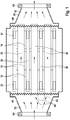
- thermoelectric generator comprises generator elements 10 which are arranged around a heat source tube 20 of a plurality of heat source tubes 20.
- a heat sink tube 30 in the form of a cooling channel for cooling liquids.
- Each generator element is thus connected on both sides between a heat source tube in the form of an exhaust passage 20 and to a heat sink tube in the form of a cooling channel 30.
- the tubes 20, 30 and the generator elements 10 are arranged in a housing 50 which is closed along its circumference and has two open ends to introduce heat source medium into the generator and to dissipate therefrom.
- the orifices are in the form of a flange 60.
- the heat sink tubes have a port 32, 34 at each of both ends, the ports 32 of all the heat sink tubes of one side of the generator being interconnected and all ports 34 of the opposite ends of the heat sink tubes being interconnected.
- the manifolds both ends each have an outwardly leading terminal which in FIG. 1 for reasons of clarity is not shown. These connections are each guided through the housing to the outside.
- the heat sink tubes are held on either side by a bottom plate 40, wherein the bottom plate 40 holds the heat sink tubes 30 in a press fit.
- the floor panels are wavy. Due to the waveform of the floor panels 40 and the thickness of these are elastic and provide a biasing force for the intermediate heat source tubes 20.
- the floor panels 40 thus each have a surface facing the end face of the heat source tubes 20 in order to compress them. Due to the waveform, it is also possible that the heat source tubes can slip, in particular with greater thermal expansion to each other and in particular with respect to the abutting bottom plate 40, wherein the offset distance of the slipping is defined by the waveform.
- openings in the bottom plate 40 are provided which provide a fluid communication between the heat source tubes and the space of the housing, which connects in continuation to the longitudinal extent of the tubes within the housing.
- the housing thus forms chambers 70 of the heat source tubes or heat sink tubes.
- the openings in the bottom plates 40 are such that, for example, exhaust gas may enter the heat source tubes 20 substantially unimpeded through the bottom plate, but at the same time prevent by their structure the heat source tubes from passing through the bottom plate.
- the end faces of the heat source tubes 20 are offset to the end faces of the heat sink tubes 30, wherein the heat source tubes project beyond the heat sink tubes on both sides. This allows a contacting of the bottom plate exclusively with the heat source tubes.
- the bottom plate is fixedly connected to the housing 50, for example by a weld or a material connection.
- the end faces of the heat source tubes 20 can perform a relative movement to the bottom plates, in particular relative to the housing 50.
- Optional arcuate elements 42 for example in the form of a semicircle or a paraboloid, which extends between two facing sides of the heat source tubes, may also be attached to the bottom plate.
- the arch members 42 may be welded to the floor panel or may be made in one piece and continuously with the floor panel, wherein the Floor panel at the points of the arch elements does not extend along a plane. At the contact points of the end faces of the heat source tubes 20 to the bottom plate, however, the bottom plate is flat in its overall form (but provided with a waveform as a macrostructure).
- the arch elements cover in their transverse extent the distance that results between adjacent heat source tubes 20 and thus cover in projection in the longitudinal direction of the generator, the heat sink tubes 30 and the generator elements 10 from.
- the solid line arrows represent the flow of the exhaust gas entering one side of the thermoelectric generator into the respective flange, passing through the heat source tubes 20 and exiting on the opposite side. It can be seen on the arrows 80 that the optional curved element 42, shown in dashed lines, divides the gas flow essentially without turbulence into adjacent heat source tubes 20.
- the flow direction of the heat sink tubes 30 is defined by the occupancy of the ports 32, 34 and may be parallel or antiparallel to the flow direction of the medium flowing through the heat source tubes 20.
- the bias bearing device is formed by the bottom plates 40 in waveform and through the end faces of the heat source tubes 20, wherein the heat source tubes experience a compressive force through the bottom plates and the waveform, optionally together with heat-related changes in length, a radial force perpendicular to the longitudinal axis of the Generator learns.
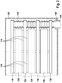
- FIG. 2 shows a second embodiment of the invention, with the aid of FIG. 1 illustrated embodiment is combinable.
- the in FIG. 2 The illustrated generator includes generator elements 110 formed between heat source tubes 120 and heat sink tubes 130.
- the FIG. 2 is a front view, that is, a cross section of the longitudinal view of FIG. 1 .
- the heat source tubes and the heat sink tubes have a flat square cross-section, so that the channel formed thereby has a large circumference with respect to its cross-sectional area. This results in a high specific volume.
- the heat sink tubes 130 are connected to one another via a flexible connection line or its sections 136.
- the connecting line connects the in FIG. 1 shown connections 32 and 34 of the heat sink tubes, ie the cooling channels.
- the connecting line serves as a manifold or as a manifold for the cooling liquid, and has a protruding through the housing 150 port 138 which is sealed by means of seals 138 'to the housing.
- the manifold and the manifold pipe 136 is flexible and thus exerts substantially no force on the heat sink tubes 130.
- the collection tube 136 is provided of elastic material so as to provide a lateral bias for the heat sink tubes 130. By biasing adjacent heat sink tubes 130 are pulled toward each other, so that results through the manifold 136, a bias bearing device.
- an elastic manifold also serves for storage, along with the elements provided between the heat sink tubes 130 (ie, heat source tubes 120 and generator elements 110).
- the manifold 136 (whether elastic or flexible) extends along an edge of the bundle formed by the heat source tubes and heat sink tubes and by the generator elements.
- the collection tube 136 extends perpendicular to the longitudinal plane of the bundle and at a height edge of the bundle.
- the manifold 136 may also extend laterally from the bundle, ie, perpendicular to the plane of extent of the bundle and to a side surface of the bundle that extends along the direction of extent of the tubes. Based on FIGS. 1 and 2 it can be seen that in the longitudinal direction of the heat sink tubes 30; 130 opposite the heat source tubes 20; 120 are shortened, but in the transverse direction extend beyond this, to allow an arrangement of the manifold 136.
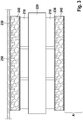
- FIG. 3 shows a cross section of an alternative embodiment of the invention in symbol representation.
- the illustrated generator includes generator elements 210 disposed between a heat source tube 220 and heat sink tubes 230.
- a housing wall 250 here exemplarily supports a heat sink tube 230, while an opposite heat sink tube 230 is supported by subsequent generator elements (and further heat source tubes) in the section A.
- a bias voltage is connected, which presses the two heat sink tubes 230 and these intermediate line components 210, 220.
- metal foam 242 is provided which presses against the inner walls of the respective tubes 230.
- the tubes 230 are thin-walled, or elastic or plastic, so that the pressure in the form of deformation can be passed to the outside.
- the tube wall of the heat sink tubes 230 transmits the spring force that the metal foam 242 exerts.
- the metal foam 242 porous or has a flow-permeable structure, so that coolant can be passed through the cooling channel 230 therethrough. Due to the porosity of the metal foam results in a significantly improved heat transfer, since the specific surface of the metal foam compared to the inner surface of a tube is significantly higher. Furthermore, results from the metal foam homogeneous application of force to the pipe inner wall. Due to the elasticity and other mechanical properties of the metal foam acts vibration damping, in particular by the fact that liquid is provided within the metal foam and thus vibrations are attenuated by (minor) turbulence or by external vibrations of the Abgasrohrsuptoms.
- the tube 230 can be made with a rectangular cross-section of high aspect ratio, i. H. with a width that is a multiple of the thickness.
- the rigidity to channels with stiffening ribs is homogeneous in the longitudinal direction and in the transverse direction of the channel. The dampening properties of the metal foam immediately increase the life of the system and prevent vibrations from creating heat gaps.
- the low velocity of the flow is more than compensated by the substantially increased specific surface of the metal foam.
- the metal foam can be used in the heat source tube or in the heat sink tube.
- the metal foam is placed in the heat sink tube because the low temperatures allow foams of different materials to be used.
- plastic foams or other materials insofar as these have a structure which allows flow in the longitudinal direction.
- an inner tube which is under radial tension can also be introduced into the heat sink tube, which generates an outwardly acting radial force.
- a radial force may also be generated, in principle, by a pressure difference existing between the interior of the heat sink tube and the surroundings of the heat sink tube.
- the heat sink or heat source tube is flexible or elastic, can be achieved by overpressure the desired bias, as far as the pipes experience a counterforce from the outside through a housing inner wall.
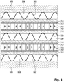
- thermoelectric generator according to the invention is shown in cross-section, which comprises a housing 350 in which thermoelectric elements 310, heat source tubes 320 and a heat sink tube 330 are provided.
- the generator elements 310 comprise paired semiconductor legs, which are alternately doped differently (p- or n-doped).
- the generator elements 310 further comprise conductor tracks (not shown), which are located at the end faces thereof.
- the generator elements are connected via a thermal paste layer 312 with an electrical insulating layer, such as ceramic 314 with the outer tube walls of the heat source tube 320 to one side and to the other side with the heat sink tube 330. It thus results for the generator elements, a temperature difference, from which generate this electrical power.
- the lower heat source tube 320 is formed of a tube wall and, opposite, through the inner surface of the housing 350.
- the lower heat source tube 320 is thus provided by an inner sheath that isolates the heat source medium from the generator elements, as well as the circumferential housing 350. This allows for material and save space; By the double use of a shell between the heat source medium or the heat sink medium can be at least for the outer tubes 320 (or 330) to save a pipe wall.
- the inner wall of the housing 350 has a dual function in that on the one hand, the housing provides a stable border as an abutment for the spring forces and on the other hand, the fluid-conducting properties of a heat source or heat sink tube.
- the spring elements 322 impinge on the inner sides of the tubes (or in the case of the lower heat source tube on the inside of the housing) and thus exert a directed to the adjacent generator elements and to the other tubes pressure.
- the walls of the tubes 320, 330 used are elastic or flexible, so as to be deformed by the spring elements 332 to the outside To be able to pass on components.
- the spring elements 332 are in FIG. 4 only symbolically represented; in particular leaf springs, coil springs or wire springs can be used, which preferably extend along the entire tube.
- spring elements may be provided, which are arranged only in longitudinal sections of the tubes, or act on these, in which case a force distribution element is provided to distribute the spring force substantially homogeneously on the inner walls of the tubes 320, 330.
- Such spring force transmission elements or elements for homogenizing the application of force can be formed from two halves of a cylinder jacket, between which the spring elements are arranged. Depending on the design of the pipe wall, however, this assumes the task of homogenizing the application of force.
- the heat source tubes and the heat sink tubes form a channel having a rectangular cross-section, in particular a cross-section having a high aspect ratio.
- the tubes preferably run parallel to one another and can be lined up next to one another in terms of their height and width.
- the generator elements are stacked in particular in a direction between the tubes, which is perpendicular to the direction of extension of the generator.
- generator elements may also be provided in the transverse extent of the generator between the tubes.
- the generator elements are coupled to the outer surfaces of the heat source or heat sink tubes via a heat transfer element, for example by means of a thermally well conductive layer.
- this layer is made electrically insulating, so that, for example, materials such as ceramic, Al 2 O 3 , AIN, steatite, fosterite, enamel or the like offer.
- the thermally well-conducting layer is not completely electrically insulated, then another electrically insulating element is used, preferably with a small thickness, in order to additionally provide electrical insulation.
- the individual generator elements or their thermoelectrically active body via a contact layer (for example, a conductor track) via a heat-connecting element, such as an electrically insulating and thermally conductive layer to the outer walls of the tubes thermally connected.
- all tubes ie all heat source and heat sink tubes, carry spring elements 322, 332 therein.
- this may only affect some of the tubes, for example only the heat sink tubes or only the heat source tubes, although not necessarily all similar tubes must carry a spring element.
- the spring element is not only provided in a tube immediately adjacent to the housing, but is also provided in a heat sink or heat source tube located within the generator and not directly adjacent to the housing. This results in a tension, which has its cause not only in the outer edge of the generator, in particular in an edge which connects directly to the housing, but also acts from within the stack. This results in a more robust, vibration-proof and homogeneous compression of the tubes with the generator elements.
Claims (10)
- Générateur thermoélectrique présentant un boîtier (50) dans lequel sont disposés au moins un tube (20) de source de chaleur, au moins un tube (30) de drain de chaleur et au moins un élément générateur (10) disposé entre le tube de source de chaleur et le tube de drain de chaleur, un ensemble (40; 136; 242; 322; 332) de palier de précontrainte étant prévu dans le boîtier et exerçant une force élastique appliquée directement sur au moins une partie des tubes (20, 30), par laquelle les tubes sont précontraints l'un vers l'autre et qui comprime ensemble les tubes (20, 30) ainsi que l'élément générateur (10) situé entre eux,
le côté intérieur du boîtier (50) présentant pour l'ensemble de palier de précontrainte un appui sur lequel une force de réaction à la force élastique de l'ensemble de palier de précontrainte est appliquée, caractérisé en ce que
l'ensemble de palier de précontrainte comporte deux plaques de fond (40) reliées solidairement au boîtier,
en ce que les tubes (20, 30) sont comprimés dans le sens de leur longueur entre des surfaces des plaques de fond tournées vers les tubes et présentent des microstructures et des macrostructures qui forment avec les côtés frontaux des tubes une correspondance mécanique dont la force d'adhérence maximale est définie ou une correspondance géométrique libérable par une force radiale maximale définie, l'ensemble de palier de précontrainte étant formé par les plaques de fond, leur surface et les côtés frontaux des tubes (20, 30) . - Générateur thermoélectrique selon la revendication 1, dans lequel les plaques de fond (40), les tubes (20, 30) ou les deux sont formés d'un matériau au moins légèrement élastique, la force maximale de retenue et la force radiale maximale étant définies par l'élasticité du matériau élastique et par la hauteur de la microstructure ou de la macrostructure, l'ensemble de palier de précontrainte montant les tubes avec deux degrés de liberté dans des directions qui s'étendent le long des surfaces et le long desquelles l'ensemble de palier de précontrainte exerce également une précontrainte qui s'applique sur les tubes et qui est formée par l'élasticité des plaques de fond ou des tubes.
- Générateur thermoélectrique selon les revendications 1 ou 2, dans lequel les surfaces ou les plaques de fond (40) présentent elles-mêmes comme macrostructures un profil ondulé ou une trame qui présente des rehaussements ou des creux qui se répètent le long de la surface dans au moins deux directions.
- Générateur thermoélectrique présentant un boîtier (50) dans lequel sont disposés au moins un tube (20) de source de chaleur, au moins un tube (30) de drain de chaleur et au moins un élément générateur (10) disposé entre le tube de source de chaleur et le tube de drain de chaleur, un ensemble (40; 136; 242; 322; 332) de palier de précontrainte étant prévu dans le boîtier et exerçant une force élastique appliquée directement sur au moins une partie des tubes (20, 30), par laquelle les tubes sont précontraints l'un vers l'autre et qui comprime ensemble les tubes (20, 30) ainsi que l'élément générateur (10) situé entre eux,
le côté intérieur du boîtier (50) présentant pour l'ensemble de palier de précontrainte un appui sur lequel une force de réaction à la force élastique de l'ensemble de palier de précontrainte est appliquée, caractérisé en ce que
l'ensemble de palier de précontrainte présente des éléments élastiques (242; 322, 332) disposés sous précontrainte dans le tube de drain de chaleur ou dans le tube de source de chaleur, la précontrainte des éléments élastiques (242; 322, 332) agissant sur des parties opposées des côtés intérieurs du tube (220, 230; 320, 330) radialement vers l'extérieur des côtés intérieurs et le tube dans lequel les éléments élastiques sont prévus étant élastique pour transmettre la précontrainte à un tube voisin ou les éléments élastiques (136) étant disposés entre des parties d'extrémité de plusieurs tubes de drain de chaleur ou tubes de source de chaleur qui débordent dans l'extension longitudinale ou l'extension transversale des tubes par l'intermédiaire des tubes de source de chaleur ou des tubes de drain de chaleur, la précontrainte des éléments élastiques s'exerçant sur des parties d'extrémité mutuellement opposées. - Générateur thermoélectrique selon la revendication 4, dans lequel les éléments élastiques (242; 322, 332) sont disposés à l'intérieur du tube de drain de chaleur ou du tube de source de chaleur et la configuration élastique des tubes dans lesquels les éléments élastiques sont disposés est fournie par une configuration de l'épaisseur de paroi et du matériau des tubes qui met ces derniers en mesure d'avoir leur section transversale modifiée par les éléments élastiques, les éléments élastiques présentant une structure perméable à l'écoulement, les éléments élastiques étant prévus sous la forme de ressorts (322, 332) à fil ou à lame précontraints dans le tube ou les éléments élastiques étant prévus sous la forme d'une mousse métallique (242) précontrainte dans le tube.
- Générateur thermoélectrique selon la revendication 4, dans lequel les éléments élastiques (136) sont prévus entre des parties d'extrémité des tubes et les éléments élastiques sont prévus sous la forme de sections d'un tube de collecte élastique dans le sens de sa longueur, qui relie à écoulement les uns aux autres plusieurs tubes (130) qui forment les parties d'extrémité, le tube de collecte élastique assurant la précontrainte entre les parties d'extrémité.
- Générateur thermoélectrique selon l'une des revendications précédentes, dans lequel les tubes de drain de chaleur ou les tubes de source de chaleur sont reliés les uns aux autres en communication hydraulique à leur partie d'extrémité par un tube flexible de collecte (136) qui n'exerce essentiellement aucune force sur les tubes, la force élastique de l'ensemble de palier de précontrainte assurant essentiellement la totalité de la précontrainte entre les tubes.
- Générateur thermoélectrique selon l'une des revendications précédentes, comprenant en outre un guide d'écoulement (42) disposé sur les côtés frontaux des tubes et dont le côté intérieur se rétrécit en direction des tubes, une chambre de collecte qui est en contact hydraulique avec tous les tubes de source de chaleur ou avec tous les tubes de drain de chaleur du générateur étant prévue à l'intérieur du boîtier sur au moins l'un des côtés frontaux, le guide d'écoulement étant prévu entre la chambre de collecte (70) et les côtés frontaux des tubes.
- Procédé de fabrication d'un générateur thermoélectrique qui présente les étapes qui consistent à :placer au moins un tube (20) de source de chaleur, au moins un tube (30) de drain de chaleur et au moins un élément générateur (10) dans un boîtier (50), un ensemble (40; 136; 242; 322, 332) de palier de précontrainte étant en outre disposé dans le boîtier et exerçant une force élastique servant à appliquer une précontrainte par laquelle les tubes (20, 30) sont précontraints directement les uns contre les autres et les tubes compriment l'élément générateur (10) situé entre eux, les tubes étant serrés dans l'ensemble (40) de palier de précontrainte,caractérisé en ce quel'ensemble de palier de précontrainte comporte deux plaques de fond (40) reliées solidairement au boîtier,en ce que les tubes (20, 30) sont comprimés dans le sens de leur longueur entre des surfaces des plaques de fond tournées vers les tubes et présentent des microstructures et des macrostructures qui forment avec les côtés frontaux des tubes une correspondance mécanique dont la force d'adhérence maximale est définie ou une correspondance géométrique libérable par une force radiale maximale définie, l'ensemble de palier de précontrainte étant formé par les plaques de fond, leur surface et les côtés frontaux des tubes (20, 30) .
- Procédé de fabrication d'un générateur thermoélectrique qui présente les étapes qui consistent à :introduire dans un boîtier (50) au moins un tube (20) de source de chaleur, au moins un tube (30) de drain de chaleur et au moins un élément générateur (10), un ensemble (40; 136; 242; 322; 332) de palier de précontrainte étant prévu dans le boîtier et exerçant directement sur au moins une partie des tubes (20, 30) une force élastique par laquelle les tubes sont précontraints l'un vers l'autre, les tubes (20, 30) ainsi que l'élément générateur (10) situé entre eux étant comprimés ensemble,l'ensemble de palier de précontrainte étant serré dans les tubes et une force étant appliquée sur les tubes par le côté intérieur du boîtier (50) qui soutient l'ensemble de palier de précontrainte, caractérisé en ce quel'ensemble de palier de précontrainte présente des éléments élastiques (242; 322, 332) disposés sous précontrainte dans le tube de drain de chaleur ou dans le tube de source de chaleur, la précontrainte des éléments élastiques (242; 322, 332) agissant sur des parties opposées des côtés intérieurs du tube (220, 230; 320, 330) radialement vers l'extérieur des côtés intérieurs et le tube dans lequel les éléments élastiques sont prévus étant élastique pour transmettre la précontrainte à un tube voisin ou les éléments élastiques (136) étant disposés entre des parties d'extrémité de plusieurs tubes de drain de chaleur ou tubes de source de chaleur qui débordent dans l'extension longitudinale ou l'extension transversale des tubes par l'intermédiaire des tubes de source de chaleur ou des tubes de drain de chaleur, la précontrainte des éléments élastiques s'exerçant sur des parties d'extrémité mutuellement opposées.
Applications Claiming Priority (2)
| Application Number | Priority Date | Filing Date | Title |
|---|---|---|---|
| DE102010001536A DE102010001536A1 (de) | 2010-02-03 | 2010-02-03 | Thermoelektrischer Generator mit integrierter vorgespannter Lagerung |
| PCT/EP2010/070183 WO2011095255A2 (fr) | 2010-02-03 | 2010-12-20 | Générateur thermoélectrique doté d'un palier précontraint intégré |
Publications (2)
| Publication Number | Publication Date |
|---|---|
| EP2531705A2 EP2531705A2 (fr) | 2012-12-12 |
| EP2531705B1 true EP2531705B1 (fr) | 2018-04-25 |
Family
ID=44146255
Family Applications (1)
| Application Number | Title | Priority Date | Filing Date |
|---|---|---|---|
| EP10795372.1A Not-in-force EP2531705B1 (fr) | 2010-02-03 | 2010-12-20 | Générateur thermoélectrique doté d'un palier précontraint intégré |
Country Status (5)
| Country | Link |
|---|---|
| US (1) | US20130152989A1 (fr) |
| EP (1) | EP2531705B1 (fr) |
| CN (1) | CN102725491B (fr) |
| DE (1) | DE102010001536A1 (fr) |
| WO (1) | WO2011095255A2 (fr) |
Families Citing this family (19)
| Publication number | Priority date | Publication date | Assignee | Title |
|---|---|---|---|---|
| DE102012206127A1 (de) * | 2012-04-13 | 2013-10-17 | Behr Gmbh & Co. Kg | Thermoelektrische Vorrichtung |
| DE102012207612B4 (de) | 2012-05-08 | 2016-09-29 | Eberspächer Exhaust Technology GmbH & Co. KG | Wärmetauscher |
| JP6338652B2 (ja) | 2013-03-15 | 2018-06-06 | ヴェカリウス・インコーポレイテッドVecarius,Inc. | 熱電装置 |
| US20150243870A1 (en) * | 2013-04-23 | 2015-08-27 | Hi-Z Technology, Inc. | Compact high power density thermoelectric generator |
| DE102013112911A1 (de) * | 2013-11-22 | 2015-06-11 | Deutsches Zentrum für Luft- und Raumfahrt e.V. | Thermoelektrische Generatorvorrichtung und Verfahren zur Herstellung einer thermoelektrischen Generatorvorrichtung |
| US10855060B2 (en) * | 2015-01-20 | 2020-12-01 | Abb Schweiz Ag | Switchgear cooling system comprising a heat pipe, fan and thermoelectric generation |
| DE102015207857A1 (de) * | 2015-04-29 | 2016-11-03 | Robert Bosch Gmbh | Thermoelektrische Vorrichtung sowie Herstellungsverfahren derselben |
| DE102015224020B4 (de) * | 2015-12-02 | 2019-05-23 | Deutsches Zentrum für Luft- und Raumfahrt e.V. | Thermoelektrisches Modul |
| US9733680B1 (en) * | 2016-03-16 | 2017-08-15 | Microsoft Technology Licensing, Llc | Thermal management system including an elastically deformable phase change device |
| GB2549123B (en) * | 2016-04-06 | 2019-10-09 | Jaguar Land Rover Ltd | Energy recovery unit for vehicle use |
| CN106545391B (zh) * | 2016-11-07 | 2019-02-22 | 威海海洋职业学院 | 一种船舶柴油机尾气余热温差能利用装置 |
| US10175003B2 (en) | 2017-02-28 | 2019-01-08 | General Electric Company | Additively manufactured heat exchanger |
| US20180244127A1 (en) * | 2017-02-28 | 2018-08-30 | General Electric Company | Thermal management system and method |
| NO342455B1 (en) | 2017-04-03 | 2018-05-22 | Tegma As | A device for generating electric power for installation to an exhaust conduit |
| GB2570507B (en) * | 2018-01-30 | 2020-05-06 | Jaguar Land Rover Ltd | Fluid flow network for a vehicle |
| JP7328664B2 (ja) * | 2018-10-04 | 2023-08-17 | 株式会社テックスイージー | 熱電変換装置 |
| DE102019114643A1 (de) * | 2019-05-31 | 2020-12-03 | Deutsches Zentrum für Luft- und Raumfahrt e.V. | Thermoelektrische Generatorvorrichtung mit mindestens einem Abstandshalter |
| DE102019121113A1 (de) * | 2019-08-05 | 2021-02-11 | Deutsches Zentrum für Luft- und Raumfahrt e.V. | Thermoelektrische Generatorvorrichtung und Verfahren zur Vergleichmäßigung eines Temperaturfelds bei einer thermoelektrischen Generatorvorrichtung |
| DE102020207712A1 (de) * | 2020-06-22 | 2021-12-23 | Eberspächer Catem Gmbh & Co. Kg | Steuervorrichtung |
Citations (1)
| Publication number | Priority date | Publication date | Assignee | Title |
|---|---|---|---|---|
| US5892656A (en) * | 1993-10-19 | 1999-04-06 | Bass; John C. | Thermoelectric generator |
Family Cites Families (11)
| Publication number | Priority date | Publication date | Assignee | Title |
|---|---|---|---|---|
| US3302621A (en) * | 1965-05-27 | 1967-02-07 | Foster Wheeler Corp | Method of supporting horizontal heater tubes fired from both sides |
| DE1539330A1 (de) * | 1966-12-06 | 1969-11-06 | Siemens Ag | Thermoelektrische Anordnung |
| JPS58153093A (ja) * | 1982-03-04 | 1983-09-10 | Kawasaki Heavy Ind Ltd | 熱電発電機用熱交換器 |
| FR2636416A1 (fr) * | 1988-09-14 | 1990-03-16 | Wojtyniak Bernard | Technique originale de fabrication des echangeurs thermiques et de montage de leur faisceau de tubes |
| JP4423989B2 (ja) | 2004-02-05 | 2010-03-03 | トヨタ自動車株式会社 | 内燃機関の熱電発電装置 |
| DE102005036768A1 (de) * | 2005-06-23 | 2006-12-28 | Webasto Ag | Heizgerät mit thermoelektrischer Einrichtung |
| JP2008072775A (ja) * | 2006-09-12 | 2008-03-27 | Nissan Motor Co Ltd | 排熱エネルギー回収装置 |
| DE102006057662A1 (de) | 2006-12-07 | 2008-06-12 | Bayerische Motoren Werke Ag | Fahrzeug mit einem thermoelektrischen Generator |
| DE102007063196A1 (de) * | 2007-12-19 | 2009-07-02 | Bayerische Motoren Werke Aktiengesellschaft | Thermoelektrischer Generator und Verfahren zur Herstellung eines thermoelektrischen Generators |
| DE102007063173A1 (de) * | 2007-12-19 | 2009-06-25 | Bayerische Motoren Werke Aktiengesellschaft | Thermoelektrischer Generator |
| AT506262B1 (de) * | 2009-04-02 | 2011-07-15 | Avl List Gmbh | Thermoelektrische generatoreinheit |
-
2010
- 2010-02-03 DE DE102010001536A patent/DE102010001536A1/de not_active Withdrawn
- 2010-12-20 US US13/577,066 patent/US20130152989A1/en not_active Abandoned
- 2010-12-20 EP EP10795372.1A patent/EP2531705B1/fr not_active Not-in-force
- 2010-12-20 CN CN201080063033.0A patent/CN102725491B/zh not_active Expired - Fee Related
- 2010-12-20 WO PCT/EP2010/070183 patent/WO2011095255A2/fr active Application Filing
Patent Citations (1)
| Publication number | Priority date | Publication date | Assignee | Title |
|---|---|---|---|---|
| US5892656A (en) * | 1993-10-19 | 1999-04-06 | Bass; John C. | Thermoelectric generator |
Also Published As
| Publication number | Publication date |
|---|---|
| EP2531705A2 (fr) | 2012-12-12 |
| DE102010001536A1 (de) | 2011-08-04 |
| CN102725491B (zh) | 2016-02-03 |
| CN102725491A (zh) | 2012-10-10 |
| WO2011095255A3 (fr) | 2011-10-13 |
| US20130152989A1 (en) | 2013-06-20 |
| WO2011095255A2 (fr) | 2011-08-11 |
Similar Documents
| Publication | Publication Date | Title |
|---|---|---|
| EP2531705B1 (fr) | Générateur thermoélectrique doté d'un palier précontraint intégré | |
| EP2567423B1 (fr) | Dispositif de refroidissement d'une batterie | |
| DE102009052254A1 (de) | Energiespeichervorrichtung | |
| DE202010018101U1 (de) | Thermoelektrische Generatorvorrichtung | |
| DE102007063196A1 (de) | Thermoelektrischer Generator und Verfahren zur Herstellung eines thermoelektrischen Generators | |
| DE102007063173A1 (de) | Thermoelektrischer Generator | |
| DE102013112911A1 (de) | Thermoelektrische Generatorvorrichtung und Verfahren zur Herstellung einer thermoelektrischen Generatorvorrichtung | |
| DE102009013535A1 (de) | Thermoelektrische Vorrichtung | |
| DE102015115643A1 (de) | Kühlmodul für eine Batterie und Batterie mit Kühlmodul | |
| DE102015210398A1 (de) | Thermoelektrischer Generator zur Umwandlung von Wärme eines heißen Gasstroms in elektrische Energie | |
| DE102011111954A1 (de) | Vorrichtung zur Abgaswärmenutzung, Abgasmodul mit einer solchen Vorrichtung sowie Verfahren zur Herstellung der Vorrichtung | |
| DE102013021312A1 (de) | Batterie | |
| DE102007063171A1 (de) | Thermoelektrisches Modul und thermoelektrischer Generator | |
| EP2865022B1 (fr) | Module thermoélectrique avec échangeur de chaleur | |
| DE102012214701A1 (de) | Thermoelektrische Vorrichtung | |
| DE102012206085B4 (de) | Wärmetauscher | |
| EP2664886A2 (fr) | Echangeur thermique | |
| DE102015107358A1 (de) | Brennstoffzellenstapel | |
| EP2700795B1 (fr) | Échangeur de chaleur | |
| DE102009034141A1 (de) | Gehäuse für eine elektrochemische Vorrichtung | |
| WO2014027014A1 (fr) | Dispositif thermoélectrique | |
| DE102007044634B4 (de) | Hochtemperatur-Polymer-Elektrolyt-Membran-Brennstoffzelle (HT-PEMFC) einschließlich Vorrichtungen zu deren Kühlung | |
| EP3689653B1 (fr) | Réacteur destiné à recevoir une matière d'accumulation et son procédé de fabrication | |
| EP1285213B1 (fr) | Echangeur de chaleur a microstructure et son procede de realisation | |
| DE102016206507A1 (de) | Thermoelektrisches Modul |
Legal Events
| Date | Code | Title | Description |
|---|---|---|---|
| PUAI | Public reference made under article 153(3) epc to a published international application that has entered the european phase |
Free format text: ORIGINAL CODE: 0009012 |
|
| 17P | Request for examination filed |
Effective date: 20120903 |
|
| AK | Designated contracting states |
Kind code of ref document: A2 Designated state(s): AL AT BE BG CH CY CZ DE DK EE ES FI FR GB GR HR HU IE IS IT LI LT LU LV MC MK MT NL NO PL PT RO RS SE SI SK SM TR |
|
| DAX | Request for extension of the european patent (deleted) | ||
| 17Q | First examination report despatched |
Effective date: 20161220 |
|
| GRAP | Despatch of communication of intention to grant a patent |
Free format text: ORIGINAL CODE: EPIDOSNIGR1 |
|
| INTG | Intention to grant announced |
Effective date: 20171215 |
|
| GRAA | (expected) grant |
Free format text: ORIGINAL CODE: 0009210 |
|
| GRAS | Grant fee paid |
Free format text: ORIGINAL CODE: EPIDOSNIGR3 |
|
| AK | Designated contracting states |
Kind code of ref document: B1 Designated state(s): AL AT BE BG CH CY CZ DE DK EE ES FI FR GB GR HR HU IE IS IT LI LT LU LV MC MK MT NL NO PL PT RO RS SE SI SK SM TR |
|
| REG | Reference to a national code |
Ref country code: GB Ref legal event code: FG4D Free format text: NOT ENGLISH |
|
| REG | Reference to a national code |
Ref country code: CH Ref legal event code: EP |
|
| REG | Reference to a national code |
Ref country code: AT Ref legal event code: REF Ref document number: 993163 Country of ref document: AT Kind code of ref document: T Effective date: 20180515 |
|
| REG | Reference to a national code |
Ref country code: IE Ref legal event code: FG4D Free format text: LANGUAGE OF EP DOCUMENT: GERMAN |
|
| REG | Reference to a national code |
Ref country code: DE Ref legal event code: R096 Ref document number: 502010014928 Country of ref document: DE |
|
| REG | Reference to a national code |
Ref country code: NL Ref legal event code: MP Effective date: 20180425 |
|
| REG | Reference to a national code |
Ref country code: LT Ref legal event code: MG4D |
|
| PG25 | Lapsed in a contracting state [announced via postgrant information from national office to epo] |
Ref country code: NL Free format text: LAPSE BECAUSE OF FAILURE TO SUBMIT A TRANSLATION OF THE DESCRIPTION OR TO PAY THE FEE WITHIN THE PRESCRIBED TIME-LIMIT Effective date: 20180425 |
|
| PG25 | Lapsed in a contracting state [announced via postgrant information from national office to epo] |
Ref country code: ES Free format text: LAPSE BECAUSE OF FAILURE TO SUBMIT A TRANSLATION OF THE DESCRIPTION OR TO PAY THE FEE WITHIN THE PRESCRIBED TIME-LIMIT Effective date: 20180425 Ref country code: NO Free format text: LAPSE BECAUSE OF FAILURE TO SUBMIT A TRANSLATION OF THE DESCRIPTION OR TO PAY THE FEE WITHIN THE PRESCRIBED TIME-LIMIT Effective date: 20180725 Ref country code: LT Free format text: LAPSE BECAUSE OF FAILURE TO SUBMIT A TRANSLATION OF THE DESCRIPTION OR TO PAY THE FEE WITHIN THE PRESCRIBED TIME-LIMIT Effective date: 20180425 Ref country code: BG Free format text: LAPSE BECAUSE OF FAILURE TO SUBMIT A TRANSLATION OF THE DESCRIPTION OR TO PAY THE FEE WITHIN THE PRESCRIBED TIME-LIMIT Effective date: 20180725 Ref country code: PL Free format text: LAPSE BECAUSE OF FAILURE TO SUBMIT A TRANSLATION OF THE DESCRIPTION OR TO PAY THE FEE WITHIN THE PRESCRIBED TIME-LIMIT Effective date: 20180425 Ref country code: SE Free format text: LAPSE BECAUSE OF FAILURE TO SUBMIT A TRANSLATION OF THE DESCRIPTION OR TO PAY THE FEE WITHIN THE PRESCRIBED TIME-LIMIT Effective date: 20180425 Ref country code: FI Free format text: LAPSE BECAUSE OF FAILURE TO SUBMIT A TRANSLATION OF THE DESCRIPTION OR TO PAY THE FEE WITHIN THE PRESCRIBED TIME-LIMIT Effective date: 20180425 |
|
| PG25 | Lapsed in a contracting state [announced via postgrant information from national office to epo] |
Ref country code: GR Free format text: LAPSE BECAUSE OF FAILURE TO SUBMIT A TRANSLATION OF THE DESCRIPTION OR TO PAY THE FEE WITHIN THE PRESCRIBED TIME-LIMIT Effective date: 20180726 Ref country code: HR Free format text: LAPSE BECAUSE OF FAILURE TO SUBMIT A TRANSLATION OF THE DESCRIPTION OR TO PAY THE FEE WITHIN THE PRESCRIBED TIME-LIMIT Effective date: 20180425 Ref country code: RS Free format text: LAPSE BECAUSE OF FAILURE TO SUBMIT A TRANSLATION OF THE DESCRIPTION OR TO PAY THE FEE WITHIN THE PRESCRIBED TIME-LIMIT Effective date: 20180425 Ref country code: LV Free format text: LAPSE BECAUSE OF FAILURE TO SUBMIT A TRANSLATION OF THE DESCRIPTION OR TO PAY THE FEE WITHIN THE PRESCRIBED TIME-LIMIT Effective date: 20180425 |
|
| PG25 | Lapsed in a contracting state [announced via postgrant information from national office to epo] |
Ref country code: PT Free format text: LAPSE BECAUSE OF FAILURE TO SUBMIT A TRANSLATION OF THE DESCRIPTION OR TO PAY THE FEE WITHIN THE PRESCRIBED TIME-LIMIT Effective date: 20180827 |
|
| REG | Reference to a national code |
Ref country code: DE Ref legal event code: R097 Ref document number: 502010014928 Country of ref document: DE |
|
| PG25 | Lapsed in a contracting state [announced via postgrant information from national office to epo] |
Ref country code: CZ Free format text: LAPSE BECAUSE OF FAILURE TO SUBMIT A TRANSLATION OF THE DESCRIPTION OR TO PAY THE FEE WITHIN THE PRESCRIBED TIME-LIMIT Effective date: 20180425 Ref country code: RO Free format text: LAPSE BECAUSE OF FAILURE TO SUBMIT A TRANSLATION OF THE DESCRIPTION OR TO PAY THE FEE WITHIN THE PRESCRIBED TIME-LIMIT Effective date: 20180425 Ref country code: SK Free format text: LAPSE BECAUSE OF FAILURE TO SUBMIT A TRANSLATION OF THE DESCRIPTION OR TO PAY THE FEE WITHIN THE PRESCRIBED TIME-LIMIT Effective date: 20180425 Ref country code: DK Free format text: LAPSE BECAUSE OF FAILURE TO SUBMIT A TRANSLATION OF THE DESCRIPTION OR TO PAY THE FEE WITHIN THE PRESCRIBED TIME-LIMIT Effective date: 20180425 Ref country code: EE Free format text: LAPSE BECAUSE OF FAILURE TO SUBMIT A TRANSLATION OF THE DESCRIPTION OR TO PAY THE FEE WITHIN THE PRESCRIBED TIME-LIMIT Effective date: 20180425 |
|
| PG25 | Lapsed in a contracting state [announced via postgrant information from national office to epo] |
Ref country code: IT Free format text: LAPSE BECAUSE OF FAILURE TO SUBMIT A TRANSLATION OF THE DESCRIPTION OR TO PAY THE FEE WITHIN THE PRESCRIBED TIME-LIMIT Effective date: 20180425 Ref country code: SM Free format text: LAPSE BECAUSE OF FAILURE TO SUBMIT A TRANSLATION OF THE DESCRIPTION OR TO PAY THE FEE WITHIN THE PRESCRIBED TIME-LIMIT Effective date: 20180425 |
|
| PLBE | No opposition filed within time limit |
Free format text: ORIGINAL CODE: 0009261 |
|
| STAA | Information on the status of an ep patent application or granted ep patent |
Free format text: STATUS: NO OPPOSITION FILED WITHIN TIME LIMIT |
|
| 26N | No opposition filed |
Effective date: 20190128 |
|
| PGFP | Annual fee paid to national office [announced via postgrant information from national office to epo] |
Ref country code: DE Payment date: 20190221 Year of fee payment: 9 |
|
| PG25 | Lapsed in a contracting state [announced via postgrant information from national office to epo] |
Ref country code: SI Free format text: LAPSE BECAUSE OF FAILURE TO SUBMIT A TRANSLATION OF THE DESCRIPTION OR TO PAY THE FEE WITHIN THE PRESCRIBED TIME-LIMIT Effective date: 20180425 |
|
| REG | Reference to a national code |
Ref country code: CH Ref legal event code: PL |
|
| GBPC | Gb: european patent ceased through non-payment of renewal fee |
Effective date: 20181220 |
|
| PG25 | Lapsed in a contracting state [announced via postgrant information from national office to epo] |
Ref country code: LU Free format text: LAPSE BECAUSE OF NON-PAYMENT OF DUE FEES Effective date: 20181220 Ref country code: MC Free format text: LAPSE BECAUSE OF FAILURE TO SUBMIT A TRANSLATION OF THE DESCRIPTION OR TO PAY THE FEE WITHIN THE PRESCRIBED TIME-LIMIT Effective date: 20180425 |
|
| REG | Reference to a national code |
Ref country code: IE Ref legal event code: MM4A |
|
| REG | Reference to a national code |
Ref country code: BE Ref legal event code: MM Effective date: 20181231 |
|
| PG25 | Lapsed in a contracting state [announced via postgrant information from national office to epo] |
Ref country code: IE Free format text: LAPSE BECAUSE OF NON-PAYMENT OF DUE FEES Effective date: 20181220 Ref country code: FR Free format text: LAPSE BECAUSE OF NON-PAYMENT OF DUE FEES Effective date: 20181231 |
|
| PG25 | Lapsed in a contracting state [announced via postgrant information from national office to epo] |
Ref country code: BE Free format text: LAPSE BECAUSE OF NON-PAYMENT OF DUE FEES Effective date: 20181231 Ref country code: AL Free format text: LAPSE BECAUSE OF FAILURE TO SUBMIT A TRANSLATION OF THE DESCRIPTION OR TO PAY THE FEE WITHIN THE PRESCRIBED TIME-LIMIT Effective date: 20180425 |
|
| PG25 | Lapsed in a contracting state [announced via postgrant information from national office to epo] |
Ref country code: CH Free format text: LAPSE BECAUSE OF NON-PAYMENT OF DUE FEES Effective date: 20181231 Ref country code: LI Free format text: LAPSE BECAUSE OF NON-PAYMENT OF DUE FEES Effective date: 20181231 Ref country code: GB Free format text: LAPSE BECAUSE OF NON-PAYMENT OF DUE FEES Effective date: 20181220 |
|
| PG25 | Lapsed in a contracting state [announced via postgrant information from national office to epo] |
Ref country code: MT Free format text: LAPSE BECAUSE OF FAILURE TO SUBMIT A TRANSLATION OF THE DESCRIPTION OR TO PAY THE FEE WITHIN THE PRESCRIBED TIME-LIMIT Effective date: 20180425 |
|
| REG | Reference to a national code |
Ref country code: AT Ref legal event code: MM01 Ref document number: 993163 Country of ref document: AT Kind code of ref document: T Effective date: 20181220 |
|
| PG25 | Lapsed in a contracting state [announced via postgrant information from national office to epo] |
Ref country code: TR Free format text: LAPSE BECAUSE OF FAILURE TO SUBMIT A TRANSLATION OF THE DESCRIPTION OR TO PAY THE FEE WITHIN THE PRESCRIBED TIME-LIMIT Effective date: 20180425 |
|
| PG25 | Lapsed in a contracting state [announced via postgrant information from national office to epo] |
Ref country code: AT Free format text: LAPSE BECAUSE OF NON-PAYMENT OF DUE FEES Effective date: 20181220 |
|
| PG25 | Lapsed in a contracting state [announced via postgrant information from national office to epo] |
Ref country code: HU Free format text: LAPSE BECAUSE OF FAILURE TO SUBMIT A TRANSLATION OF THE DESCRIPTION OR TO PAY THE FEE WITHIN THE PRESCRIBED TIME-LIMIT; INVALID AB INITIO Effective date: 20101220 Ref country code: MK Free format text: LAPSE BECAUSE OF NON-PAYMENT OF DUE FEES Effective date: 20180425 Ref country code: CY Free format text: LAPSE BECAUSE OF FAILURE TO SUBMIT A TRANSLATION OF THE DESCRIPTION OR TO PAY THE FEE WITHIN THE PRESCRIBED TIME-LIMIT Effective date: 20180425 |
|
| REG | Reference to a national code |
Ref country code: DE Ref legal event code: R119 Ref document number: 502010014928 Country of ref document: DE |
|
| PG25 | Lapsed in a contracting state [announced via postgrant information from national office to epo] |
Ref country code: IS Free format text: LAPSE BECAUSE OF FAILURE TO SUBMIT A TRANSLATION OF THE DESCRIPTION OR TO PAY THE FEE WITHIN THE PRESCRIBED TIME-LIMIT Effective date: 20180825 |
|
| PG25 | Lapsed in a contracting state [announced via postgrant information from national office to epo] |
Ref country code: DE Free format text: LAPSE BECAUSE OF NON-PAYMENT OF DUE FEES Effective date: 20200701 |