EP2531705B1 - Thermoelectric generator with integrated preloaded mounting - Google Patents
Thermoelectric generator with integrated preloaded mounting Download PDFInfo
- Publication number
- EP2531705B1 EP2531705B1 EP10795372.1A EP10795372A EP2531705B1 EP 2531705 B1 EP2531705 B1 EP 2531705B1 EP 10795372 A EP10795372 A EP 10795372A EP 2531705 B1 EP2531705 B1 EP 2531705B1
- Authority
- EP
- European Patent Office
- Prior art keywords
- pipes
- tubes
- pipe
- heat sink
- heat source
- Prior art date
- Legal status (The legal status is an assumption and is not a legal conclusion. Google has not performed a legal analysis and makes no representation as to the accuracy of the status listed.)
- Not-in-force
Links
Images
Classifications
-
- F—MECHANICAL ENGINEERING; LIGHTING; HEATING; WEAPONS; BLASTING
- F01—MACHINES OR ENGINES IN GENERAL; ENGINE PLANTS IN GENERAL; STEAM ENGINES
- F01N—GAS-FLOW SILENCERS OR EXHAUST APPARATUS FOR MACHINES OR ENGINES IN GENERAL; GAS-FLOW SILENCERS OR EXHAUST APPARATUS FOR INTERNAL COMBUSTION ENGINES
- F01N5/00—Exhaust or silencing apparatus combined or associated with devices profiting from exhaust energy
- F01N5/02—Exhaust or silencing apparatus combined or associated with devices profiting from exhaust energy the devices using heat
- F01N5/025—Exhaust or silencing apparatus combined or associated with devices profiting from exhaust energy the devices using heat the device being thermoelectric generators
-
- H—ELECTRICITY
- H10—SEMICONDUCTOR DEVICES; ELECTRIC SOLID-STATE DEVICES NOT OTHERWISE PROVIDED FOR
- H10N—ELECTRIC SOLID-STATE DEVICES NOT OTHERWISE PROVIDED FOR
- H10N10/00—Thermoelectric devices comprising a junction of dissimilar materials, i.e. devices exhibiting Seebeck or Peltier effects
- H10N10/01—Manufacture or treatment
-
- H—ELECTRICITY
- H10—SEMICONDUCTOR DEVICES; ELECTRIC SOLID-STATE DEVICES NOT OTHERWISE PROVIDED FOR
- H10N—ELECTRIC SOLID-STATE DEVICES NOT OTHERWISE PROVIDED FOR
- H10N10/00—Thermoelectric devices comprising a junction of dissimilar materials, i.e. devices exhibiting Seebeck or Peltier effects
- H10N10/10—Thermoelectric devices comprising a junction of dissimilar materials, i.e. devices exhibiting Seebeck or Peltier effects operating with only the Peltier or Seebeck effects
- H10N10/13—Thermoelectric devices comprising a junction of dissimilar materials, i.e. devices exhibiting Seebeck or Peltier effects operating with only the Peltier or Seebeck effects characterised by the heat-exchanging means at the junction
-
- F—MECHANICAL ENGINEERING; LIGHTING; HEATING; WEAPONS; BLASTING
- F28—HEAT EXCHANGE IN GENERAL
- F28F—DETAILS OF HEAT-EXCHANGE AND HEAT-TRANSFER APPARATUS, OF GENERAL APPLICATION
- F28F2265/00—Safety or protection arrangements; Arrangements for preventing malfunction
- F28F2265/26—Safety or protection arrangements; Arrangements for preventing malfunction for allowing differential expansion between elements
-
- Y—GENERAL TAGGING OF NEW TECHNOLOGICAL DEVELOPMENTS; GENERAL TAGGING OF CROSS-SECTIONAL TECHNOLOGIES SPANNING OVER SEVERAL SECTIONS OF THE IPC; TECHNICAL SUBJECTS COVERED BY FORMER USPC CROSS-REFERENCE ART COLLECTIONS [XRACs] AND DIGESTS
- Y02—TECHNOLOGIES OR APPLICATIONS FOR MITIGATION OR ADAPTATION AGAINST CLIMATE CHANGE
- Y02T—CLIMATE CHANGE MITIGATION TECHNOLOGIES RELATED TO TRANSPORTATION
- Y02T10/00—Road transport of goods or passengers
- Y02T10/10—Internal combustion engine [ICE] based vehicles
- Y02T10/12—Improving ICE efficiencies
Definitions
- thermoelectric generators To use the heat energy of, for example, internal combustion engines, it is known to use thermoelectric generators.
- the document relates DE 10 2006 057 662 A1 a vehicle with a thermoelectric generator in which heat sources and heat sinks are arranged in their longitudinal course perpendicular to each other in the stack, wherein there are thermoelectric elements between the individual heat sources and heat sinks.
- Heat source and heat sink are provided by a plurality of heat conductive tubes, wherein the thermoelectric generator elements are integrated between the tubes.
- thermoelectric generators with radially acting spring elements therefore have a structure in which initially the heat sink, heat source and the generator elements are integrated with each other and Only from the outside spring elements act on the integrated structure, supported by an outer circumferential holder.
- the DE 10 2005 036 768 A1 discloses a heater having a thermoelectric device with a plurality of thermocouple legs.
- US5,892,656 discloses a thermoelectric generator having at least one hot side heat exchanger and at least one cold side heat exchanger and at least one thermoelectric module having thermoelectric elements installed in an injection-molded egg grid. The thermoelectric modules are held in close contact with the hot side heat exchanger and the cold side heat exchanger by spring force.
- Thermoelectric generators according to the prior art are thus limited in their degree of integration to single-layered concentric structures.
- the known spring structure is not suitable for high temperature differences or temperature changes, since many of the generator elements, especially the inner generator elements, lose their thermal coupling with strong temperature differences on heat-related column, without this can be compensated by spring action, since usually arranged spring elements provide a high thermal resistance.
- thermoelectric generator allows any degree of integration, without internal generator elements would be acted upon with an insufficient spring force.
- the arrangement according to the invention makes it possible, in particular, to preload the generator elements and associated tubes (which serve as a collection source or heat sink), which are of the Location of the respective generator element in the thermoelectric generator is independent.
- spring element assemblies according to the invention allow only the outer elements to be subjected to a spring force, with further inner generator elements not receiving sufficient spring force to maintain contact with the heat sink and the heat source in the event of temperature changes or even vibrations.
- the inventive structure allows any number of tubes and generator elements can be combined to form a compact generator, which automatically the specific surface, the integration density or the generator power based on the generator volume can be significantly increased.
- the device according to the invention can be provided with simple means, in particular without spring elements and support structures concentrated around the actual generator, which form the abutment for the entire spring force.
- the arrangement according to the invention allows a space-saving integration of the elements that press the generator elements on the respective tubes in a wide temperature range. In particular, this reduces the circumference of the generator while maintaining power (or increased power) over the prior art.
- the concept underlying the invention is to provide the spring elements not around the outer tubes, but integrated in the generator structure. While the prior art merely provides for external force and spring force only for the outer tubes, the invention provides for providing a biasing bearing device which biases the tubes themselves to each other and thereby the intermediate generator element by means of the tubes compresses.
- the spring force generating element is in this case provided at least partly between the tubes, provided in the tubes, provided by the tubes themselves, or is provided, for example as a subcomponent, on the end face of the tubes.
- the preload bearing element exerts the force directly on the tubes, either by arranging spring elements in the tubes themselves, on the front sides of the tubes (as a subcomponent) or by suitable storage of the tubes to their spring force or the spring force of a front-side bracket immediately to act on the pipes.
- the tube walls are used themselves, optionally alternatively or in combination with a front-side support which provides a bottom plate, or by spring elements which are located within the tubes and thus provide no to be bridged thermal resistance between a generator element and a tube outside.
- the arrangement according to the invention allows equally not only tubes lying in the outermost layer to be subjected to a spring force.
- the preload bearing device is not provided exclusively on the outside of the thermoelectric generator but also within the generator (ie within the tubes or at the end faces), together with force distributing elements or spring elements provided by the tube walls themselves, directly around the spring force on internal, ie to distribute all components.
- the device according to the invention generates a predetermined spring force which is below a defined maximum spring force, substantially independent of the operating temperature interval.
- the thermoelectric generator according to the invention comprises a housing in which at least one heat source tube, at least one heat sink tube, and at least one generator element is arranged, the generator element being disposed between the dissimilar tubes (i.e., between a heat source tube and a heat sink tube).
- the preload bearing device according to the invention provides a spring force acting between the tubes, i. H. which serves to bias the tubes to each other.
- the spring force acts directly on the pipes themselves and is not transmitted from the outside pipe to pipe inside, such a transmission would drop the amount of spring force from outside to inside clearly.
- the biasing bearing device acts directly on the tubes themselves, regardless of their distance from the center of the thermoelectric generator.
- the bias bearing device thus compresses generator elements by exerting pressure on tubes that directly adjoin the generator element.
- the biasing bearing device is further distributed across the cross section of the generator and exerts immediate force on the tubes by the biasing bearing device is either located directly on the end faces of the tubes or provided by the tube walls themselves or produced by spring elements present in the tubes becomes.
- Between preload bearing device and pipes thus results in a direct mechanical contact, in particular by (partial) identity between preload bearing device and pipes, by frictional connection between preload bearing device and pipes or by positive engagement between preload bearing device and pipe. This applies to all tubes of the thermoelectric generator, in particular for the inner tubes.
- the bias bearing device serves as an inner surface of the housing as an abutment.
- the inside of the housing thus provides a support for the preload bearing device, wherein due to the adjustment of the spring forces, the support is subjected to a counter force of the spring force of the preload bearing device.
- the amount of drag may correspond to the spring force that the bias bearing device applies to the tubes.
- the bias bearing device serves for a storage of the tubes and on the other to generate bias.
- the storage allows a displacement of the tubes with each other to compensate for strong temperature changes movements that result from different thermal expansions.
- the bearing provided by the preload bearing device may also be provided by a sprung, ie prestressed, bearing, allowing compensation of the spring forces acting on the tubes by movement or deformation of the tubes.
- the tubes are clamped between bottom plates.
- the surface of the bottom plates have micro or macrostructures to hold the end faces of the tubes in place. Due to the force with which the bottom plates press on the end faces of the tubes, there is a frictional connection with a defined maximum adhesive force resulting from the material and in particular from the microstructures, together with the contact pressure (ie normal force) with which the Pipes act on the floor slabs.
- a microstructure in particular a roughened metal surface is suitable, for example by brushing or the like.
- the bias bearing device is formed by the bottom plates, in particular by the surfaces of the bottom plates, and by the end faces of the tubes.
- the floor panels themselves can be provided elastically.
- the pipes themselves may be provided elastically, so that the pipe walls themselves provide the spring effect.
- the tubes serve to transmit the spring action over the length of the tubes, so that the tubes are formed with a low elasticity.
- the tubes are substantially rigid and exert a strong spring force even at low deflections.
- This is made possible by providing the bottom plate or the tubes (or both) at least slightly elastic, ie of elastic material and with an elastic structure. Based on the elasticity and the dimensions of the base plate and tube, the maximum adhesive force and the maximum radial force can be accurately provided depending on the bias of the tubes in longitudinal force, from which the frictional or positive connection between the tube and bottom plate yields and slipping allows.
- the distinction between positive locking and traction depends essentially on the consideration of the structures of the bottom plate surfaces. Even mutually rubbing microstructures can be considered as a releasable positive locking when elevations of the microstructures are considered as a form-locking form, which yield due to their elasticity or plasticity.
- the height of the maximum adhesion force and the maximum radial force thus also depends on the height of the microstructure or macrostructure, on the materials used and the bendability of the base plates or the tubes. Since all the necessary parameters can be determined in a simple manner, for example using a material table with elasticity and adhesive force data, it is familiar to the person skilled in the art how the individual components are to be designed if a specific maximum adhesion force or maximum radial force is to be generated.
- the longitudinal bias of the tubes depends on the material constants and the dimensions of the components, in particular the thickness of the bottom plates, the wall thickness of the tubes, the length of the tubes and their materials.
- the surfaces or floor panels themselves may be roughened by any method and thus have microstructures defining the adhesive force. Furthermore, targeted layers can be applied to the bottom plates to increase or decrease the adhesion.
- a preferred embodiment provides, however, that the surface of the bottom plates or the bottom plates themselves are provided with macrostructures which are, for example, greater than 100 ⁇ m, greater than 200 ⁇ m or greater than 500 ⁇ m, in particular greater than 1 mm or 2 mm.
- the macrostructures may have a grid composed of straight grooves, for example, grooves along two different directions straight along the surface.
- the macrostructures may also be shown with shallow grooves, for example with a depth of 0.5 or 1 mm.
- the peaks and valleys may be one-dimensional and extend only from the surface, or may extend away from the surface as well as along a direction along the surface.
- the macrostructures are equipped such that they can not tilt with the end faces of the tubes.
- the elevations or depressions are provided in cross-section with surfaces which extend at an angle of substantially less than 90 ° to the surface, for example with an angle of maximum 60 °, 45 ° or 30 °. This prevents jamming, even if the macrostructures are particularly large.
- structures are used with surfaces that do not tilt in multiple directions of displacement.
- a continuous course of the structures is preferred, for example a wave course or a triangular course (no sawtooth course).
- the bottom plate itself is integrally connected to the housing or otherwise attached to this in such a way that the bottom plates in the housing can not move in the longitudinal direction of the tubes.
- the other type of tubes may be materially connected to the bottom plate, for example by welding.
- the heat sources can be materially connected to the bottom plate, for example by a welded connection, and only the cooling channels are slidably mounted on the bottom plate.
- Rohrart are on the one hand all heat source tubes referred to and on the other all heat sink tubes.
- the heat sink tubes are welded to the bottom plates and the heat source tubes are arranged on the bottom plates by means of a material connection or positive connection, no structural problems arise even with large changes in the operating temperatures since the heat source tubes always have one Higher temperature than the heat sink tubes are exposed and thus automatically experience a higher thermal expansion.
- the described embodiments may further be provided with a common manifold disposed at the ends of the respective tubes and interconnecting the tubes.
- the manifold extends perpendicular to the longitudinal extent of the heat sink or heat source tubes and is preferably designed to be elastic or flexible. In the flexible embodiment, the manifold produces no bias for the pipes extending perpendicular thereto, so that the bias bearing device generates substantially all the tension forces.
- the manifold may be provided elastically to provide at least a portion of the biasing bearing direction. Such embodiments are described below.
- the preload bearing device comprises spring elements which are not provided by the tube wall or by the heat source or heat sink tube itself, optionally together with the bottom plates, but the preload bearing device is provided by individual spring elements. These are arranged within the heat sink tube or within the heat source tube under bias in this tube.
- the heat sink tube or heat source tube in this case has a wall which is elastic and is able to transmit the deformation, which results from the bias of the spring elements in the tubes in the area (outside), which surrounds the tube.
- the bias of the spring elements acts on opposite portions of inner sides of the tube. The direction of action is radial, relative to the longitudinal axis of the collecting source tube or the heat sink tube, in which the spring elements are located.
- the tube in which the spring elements are provided is designed to be elastic (by elastic equipment of the pipe wall), the bias is passed to an adjacent pipe, in particular via the generator elements.
- the flexible or elastic configuration of the tubes the deformation is used by the internal spring elements for clamping the generator elements.
- the spring elements themselves have a cross-sectional area which is significantly smaller than the cross-sectional area of the channel defined by the tubes in which the spring element is provided. The spring element and in particular its cross section is therefore designed to allow a flow within the tube and to influence the flow only slightly.
- individual spring elements are also used, but are arranged between end portions (i.e., at end faces) of a plurality of heat sink tubes.
- the end portions protrude beyond the heat source tubes.
- the spring elements can be arranged between end sections of the heat source tubes, these extending beyond the heat sink in the longitudinal direction of the tubes.
- some of the heat sink or heat source tubes may protrude beyond the other tubes in length, with the spring elements being provided between the protruding tubes and biasing them, in particular with a bias which forces the tubes connected by the spring elements apart.
- the spring elements themselves thus exert force directly on the end sections themselves, which protrude in the longitudinal direction relative to other tubes.
- the acting on the end portions of the tubes spring elements can take the place of the bottom plates. Due to the rigidity of the heat sink tubes and heat source tubes, the force exerted by the spring elements distributed along the longitudinal extent of the tubes. In particular, by the spring elements opposite end portions of the tubes are biased to each other, which are located at the same end of the generator.
- the tubes are made elastic or flexible by the wall thickness or the material of the tubes are selected such that a deformation by the spring elements is possible to compensate for height tolerances , Since this depends on the spring force of the spring elements, the wall thickness or the material of the tubes determined by the spring elements.
- the wall thickness may be extremely thin depending on the medium carried in the tube, for example in the form of a steel foil or the like.
- the spring elements are provided with a flow-permeable structure, in particular by designing the profile.
- the spring elements are provided for example by means of leaf or wire springs, which are optionally aligned along the longitudinal extent of the tube and is provided by the orientation of a minimal profile surface within the tube cross-section.
- the spring elements may be provided by metal foam, which is biased in the pipe.
- the metal foam can either be introduced into the tube cooled strongly, or the tube can first be heated before the metal foam (possibly cooled) is introduced.
- the biases of the metal foam which are directed at the wall of the tube, result.
- the metal foam is open-pored and allows the passage of fluid.
- liquid as a fluid such as cooling water
- the metal foam allows a significantly higher specific surface area, so that the heat transfer to the liquid medium is greatly increased.
- the connection of the metal foam to the wall takes place in the material connection, whereby a good heat conduction arises.
- the assembly is done by pre-pressing.
- the spring elements are provided between end portions of the tubes (i.e., between end portions of tubes which protrude from other tubes)
- the spring elements are provided by portions of a tube elastic in its longitudinal direction.
- a manifold connects by means of its portions, the end portions of the tubes.
- the heat source or heat sink tubes are connected to each other via the manifold in fluid communication which protrude from the heat sink or heat source tubes having no end portion connected to the manifold.
- the elastic collecting tube in particular its elasticity in its longitudinal direction, provides the bias between the end sections.
- the manifold is substantially perpendicular to the tubes, d. H. to the heat sink and heat source tubes, and to their end sections.
- a similar collection tube is provided, which however is flexible and exerts substantially no force on the tubes, in particular not on the end sections.
- the flexible manifolds may be provided as the elastic manifolds.
- a preload bearing apparatus according to the invention is provided which provides substantially all of the preload between the tubes.
- the manifold itself provides the preload bearing device.
- An elastic collecting tube serves, on the one hand, to movably support the heat source or heat sink tubes and, on the other hand, to exert a prestress between the tubes.
- the flexible and the elastic manifold are connected to the tubes, which form the outstanding end sections.
- the thermoelectric generator according to the invention may further comprise a flow guide, which is arranged on the end faces of the tubes, that is, the heat sink and heat source tubes. This is tapered to the tubes and opens in a direction away from the tubes, for example in the direction of a collection chamber.
- a collection chamber is on at least one of the end faces of the heat sink and heat source tubes arranged and is in fluid contact with all similar tubes, ie with all heat source tubes or with all heat sink tubes.
- the collection chamber can also be in fluid contact only with a part of similar tubes.
- the flow guide is provided between the collecting chamber and the end faces of the tubes, ie the inlets of the tubes.
- the flow guide has a taper for each tube, preferably an arcuate, continuous taper or a taper whose taper angle changes abruptly. However, arcuate elements can also be connected to sections whose taper angle changes abruptly.
- the openings of a bottom plate are just one type of tube, d. H. assigned to the heat sink tubes or the heat source tubes, wherein the bottom plate provides no opening or connection for the other type of tubes.
- these different types of pipes are assigned.
- the bottom plates are followed, on the side facing away from the tubes, a collection chamber, via which the tubes are charged with the appropriate medium.
- the recessed tubes are in fluid communication with a collection chamber which attaches to the tubes on the same side as the header.
- the recessed tubes are equipped with a medium that is different from the medium, which is located in the manifold. Since the medium in the collecting tube basically has a different temperature than the medium in the collecting chamber, a heat insulation is preferably provided which separates the collecting tube from the collecting chamber with respect to heat transfer. Otherwise, the manifold may extend partially through the collection chamber, but these are fluidly separated and are also preferably thermally insulated from each other.
- the invention is further implemented by a method for producing the thermoelectric generator according to the invention.
- a housing at least one heat source tube, at least one heat sink tube and at least one generator element introduced, wherein the generator element between the heat source tube and the heat sink tube is arranged.
- a biasing bearing device is further arranged, which generates a spring force for exerting the bias voltage, with which the tubes are biased to each other and thereby compress the tubes, the intermediate generator element.
- the tubes are clamped in the preload bearing device when the preload bearing device according to the first aspect of the invention comprises base plates, or the preload bearing device is introduced into the tubes, ie clamped under pretension in the tubes.
- the bias bearing device when the bias bearing device is provided by individual, located in the tubes spring elements, for example by inserting leaf spring elements, wire spring elements or metal foam under prestress.
- a bias between the tubes and the insides of the housing is also provided by applying a force to the inside of the housing, thereby supporting the preload bearing device from the housing.
- the pipes, d. H. the heat source tubes, the heat sink tubes and the headers, as well as the housing and the floor panels are made of metal, preferably of steel, aluminum or copper.
- metal preferably of steel, aluminum or copper.
- leaf or wire springs these are preferably made of spring steel, in particular with a weather-resistant coating to protect the spring elements from the corresponding heat medium.
- metal foam this is preferably made of aluminum or of other metals or alloys.
- the biasing force is adjusted by proper selection of the pore size as well as the amount of deformation that results in the preload.
- the housing itself may further include flanges disposed on both sides of the generator. Between the flange and the end faces of the tubes, the collection chamber is formed within the housing. In addition, connections may be provided which are connected via flexible connecting pipes to the respective heat sink or heat source tube. In particular, the flange is used for supplying gaseous media, in particular hot combustion gas. This results in a low backwater for an internal combustion engine to be connected thereto.
- the generator further preferably comprises on both sides of a flexible or elastic collection tube, which the heat sink tubes connects to each other on both sides of the generator in order to supply cooling liquid to the generator and remove it from the generator.
- the generator elements preferably comprise doped semiconductor material, in particular at least one body which is n-doped, and at least one further body which is p-doped. Furthermore, the generator elements comprise an electrically conductive connection contact which connects the differently doped semiconductor elements to one another, as well as a connection contact for positive pole or negative pole.
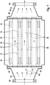
- thermoelectric generator comprises generator elements 10 which are arranged around a heat source tube 20 of a plurality of heat source tubes 20.
- a heat sink tube 30 in the form of a cooling channel for cooling liquids.
- Each generator element is thus connected on both sides between a heat source tube in the form of an exhaust passage 20 and to a heat sink tube in the form of a cooling channel 30.
- the tubes 20, 30 and the generator elements 10 are arranged in a housing 50 which is closed along its circumference and has two open ends to introduce heat source medium into the generator and to dissipate therefrom.
- the orifices are in the form of a flange 60.
- the heat sink tubes have a port 32, 34 at each of both ends, the ports 32 of all the heat sink tubes of one side of the generator being interconnected and all ports 34 of the opposite ends of the heat sink tubes being interconnected.
- the manifolds both ends each have an outwardly leading terminal which in FIG. 1 for reasons of clarity is not shown. These connections are each guided through the housing to the outside.
- the heat sink tubes are held on either side by a bottom plate 40, wherein the bottom plate 40 holds the heat sink tubes 30 in a press fit.
- the floor panels are wavy. Due to the waveform of the floor panels 40 and the thickness of these are elastic and provide a biasing force for the intermediate heat source tubes 20.
- the floor panels 40 thus each have a surface facing the end face of the heat source tubes 20 in order to compress them. Due to the waveform, it is also possible that the heat source tubes can slip, in particular with greater thermal expansion to each other and in particular with respect to the abutting bottom plate 40, wherein the offset distance of the slipping is defined by the waveform.
- openings in the bottom plate 40 are provided which provide a fluid communication between the heat source tubes and the space of the housing, which connects in continuation to the longitudinal extent of the tubes within the housing.
- the housing thus forms chambers 70 of the heat source tubes or heat sink tubes.
- the openings in the bottom plates 40 are such that, for example, exhaust gas may enter the heat source tubes 20 substantially unimpeded through the bottom plate, but at the same time prevent by their structure the heat source tubes from passing through the bottom plate.
- the end faces of the heat source tubes 20 are offset to the end faces of the heat sink tubes 30, wherein the heat source tubes project beyond the heat sink tubes on both sides. This allows a contacting of the bottom plate exclusively with the heat source tubes.
- the bottom plate is fixedly connected to the housing 50, for example by a weld or a material connection.
- the end faces of the heat source tubes 20 can perform a relative movement to the bottom plates, in particular relative to the housing 50.
- Optional arcuate elements 42 for example in the form of a semicircle or a paraboloid, which extends between two facing sides of the heat source tubes, may also be attached to the bottom plate.
- the arch members 42 may be welded to the floor panel or may be made in one piece and continuously with the floor panel, wherein the Floor panel at the points of the arch elements does not extend along a plane. At the contact points of the end faces of the heat source tubes 20 to the bottom plate, however, the bottom plate is flat in its overall form (but provided with a waveform as a macrostructure).
- the arch elements cover in their transverse extent the distance that results between adjacent heat source tubes 20 and thus cover in projection in the longitudinal direction of the generator, the heat sink tubes 30 and the generator elements 10 from.
- the solid line arrows represent the flow of the exhaust gas entering one side of the thermoelectric generator into the respective flange, passing through the heat source tubes 20 and exiting on the opposite side. It can be seen on the arrows 80 that the optional curved element 42, shown in dashed lines, divides the gas flow essentially without turbulence into adjacent heat source tubes 20.
- the flow direction of the heat sink tubes 30 is defined by the occupancy of the ports 32, 34 and may be parallel or antiparallel to the flow direction of the medium flowing through the heat source tubes 20.
- the bias bearing device is formed by the bottom plates 40 in waveform and through the end faces of the heat source tubes 20, wherein the heat source tubes experience a compressive force through the bottom plates and the waveform, optionally together with heat-related changes in length, a radial force perpendicular to the longitudinal axis of the Generator learns.
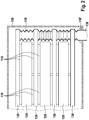
- FIG. 2 shows a second embodiment of the invention, with the aid of FIG. 1 illustrated embodiment is combinable.
- the in FIG. 2 The illustrated generator includes generator elements 110 formed between heat source tubes 120 and heat sink tubes 130.
- the FIG. 2 is a front view, that is, a cross section of the longitudinal view of FIG. 1 .
- the heat source tubes and the heat sink tubes have a flat square cross-section, so that the channel formed thereby has a large circumference with respect to its cross-sectional area. This results in a high specific volume.
- the heat sink tubes 130 are connected to one another via a flexible connection line or its sections 136.
- the connecting line connects the in FIG. 1 shown connections 32 and 34 of the heat sink tubes, ie the cooling channels.
- the connecting line serves as a manifold or as a manifold for the cooling liquid, and has a protruding through the housing 150 port 138 which is sealed by means of seals 138 'to the housing.
- the manifold and the manifold pipe 136 is flexible and thus exerts substantially no force on the heat sink tubes 130.
- the collection tube 136 is provided of elastic material so as to provide a lateral bias for the heat sink tubes 130. By biasing adjacent heat sink tubes 130 are pulled toward each other, so that results through the manifold 136, a bias bearing device.
- an elastic manifold also serves for storage, along with the elements provided between the heat sink tubes 130 (ie, heat source tubes 120 and generator elements 110).
- the manifold 136 (whether elastic or flexible) extends along an edge of the bundle formed by the heat source tubes and heat sink tubes and by the generator elements.
- the collection tube 136 extends perpendicular to the longitudinal plane of the bundle and at a height edge of the bundle.
- the manifold 136 may also extend laterally from the bundle, ie, perpendicular to the plane of extent of the bundle and to a side surface of the bundle that extends along the direction of extent of the tubes. Based on FIGS. 1 and 2 it can be seen that in the longitudinal direction of the heat sink tubes 30; 130 opposite the heat source tubes 20; 120 are shortened, but in the transverse direction extend beyond this, to allow an arrangement of the manifold 136.
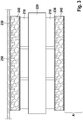
- FIG. 3 shows a cross section of an alternative embodiment of the invention in symbol representation.
- the illustrated generator includes generator elements 210 disposed between a heat source tube 220 and heat sink tubes 230.
- a housing wall 250 here exemplarily supports a heat sink tube 230, while an opposite heat sink tube 230 is supported by subsequent generator elements (and further heat source tubes) in the section A.
- a bias voltage is connected, which presses the two heat sink tubes 230 and these intermediate line components 210, 220.
- metal foam 242 is provided which presses against the inner walls of the respective tubes 230.
- the tubes 230 are thin-walled, or elastic or plastic, so that the pressure in the form of deformation can be passed to the outside.
- the tube wall of the heat sink tubes 230 transmits the spring force that the metal foam 242 exerts.
- the metal foam 242 porous or has a flow-permeable structure, so that coolant can be passed through the cooling channel 230 therethrough. Due to the porosity of the metal foam results in a significantly improved heat transfer, since the specific surface of the metal foam compared to the inner surface of a tube is significantly higher. Furthermore, results from the metal foam homogeneous application of force to the pipe inner wall. Due to the elasticity and other mechanical properties of the metal foam acts vibration damping, in particular by the fact that liquid is provided within the metal foam and thus vibrations are attenuated by (minor) turbulence or by external vibrations of the Abgasrohrsuptoms.
- the tube 230 can be made with a rectangular cross-section of high aspect ratio, i. H. with a width that is a multiple of the thickness.
- the rigidity to channels with stiffening ribs is homogeneous in the longitudinal direction and in the transverse direction of the channel. The dampening properties of the metal foam immediately increase the life of the system and prevent vibrations from creating heat gaps.
- the low velocity of the flow is more than compensated by the substantially increased specific surface of the metal foam.
- the metal foam can be used in the heat source tube or in the heat sink tube.
- the metal foam is placed in the heat sink tube because the low temperatures allow foams of different materials to be used.
- plastic foams or other materials insofar as these have a structure which allows flow in the longitudinal direction.
- an inner tube which is under radial tension can also be introduced into the heat sink tube, which generates an outwardly acting radial force.
- a radial force may also be generated, in principle, by a pressure difference existing between the interior of the heat sink tube and the surroundings of the heat sink tube.
- the heat sink or heat source tube is flexible or elastic, can be achieved by overpressure the desired bias, as far as the pipes experience a counterforce from the outside through a housing inner wall.
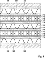
- thermoelectric generator according to the invention is shown in cross-section, which comprises a housing 350 in which thermoelectric elements 310, heat source tubes 320 and a heat sink tube 330 are provided.
- the generator elements 310 comprise paired semiconductor legs, which are alternately doped differently (p- or n-doped).
- the generator elements 310 further comprise conductor tracks (not shown), which are located at the end faces thereof.
- the generator elements are connected via a thermal paste layer 312 with an electrical insulating layer, such as ceramic 314 with the outer tube walls of the heat source tube 320 to one side and to the other side with the heat sink tube 330. It thus results for the generator elements, a temperature difference, from which generate this electrical power.
- the lower heat source tube 320 is formed of a tube wall and, opposite, through the inner surface of the housing 350.
- the lower heat source tube 320 is thus provided by an inner sheath that isolates the heat source medium from the generator elements, as well as the circumferential housing 350. This allows for material and save space; By the double use of a shell between the heat source medium or the heat sink medium can be at least for the outer tubes 320 (or 330) to save a pipe wall.
- the inner wall of the housing 350 has a dual function in that on the one hand, the housing provides a stable border as an abutment for the spring forces and on the other hand, the fluid-conducting properties of a heat source or heat sink tube.
- the spring elements 322 impinge on the inner sides of the tubes (or in the case of the lower heat source tube on the inside of the housing) and thus exert a directed to the adjacent generator elements and to the other tubes pressure.
- the walls of the tubes 320, 330 used are elastic or flexible, so as to be deformed by the spring elements 332 to the outside To be able to pass on components.
- the spring elements 332 are in FIG. 4 only symbolically represented; in particular leaf springs, coil springs or wire springs can be used, which preferably extend along the entire tube.
- spring elements may be provided, which are arranged only in longitudinal sections of the tubes, or act on these, in which case a force distribution element is provided to distribute the spring force substantially homogeneously on the inner walls of the tubes 320, 330.
- Such spring force transmission elements or elements for homogenizing the application of force can be formed from two halves of a cylinder jacket, between which the spring elements are arranged. Depending on the design of the pipe wall, however, this assumes the task of homogenizing the application of force.
- the heat source tubes and the heat sink tubes form a channel having a rectangular cross-section, in particular a cross-section having a high aspect ratio.
- the tubes preferably run parallel to one another and can be lined up next to one another in terms of their height and width.
- the generator elements are stacked in particular in a direction between the tubes, which is perpendicular to the direction of extension of the generator.
- generator elements may also be provided in the transverse extent of the generator between the tubes.
- the generator elements are coupled to the outer surfaces of the heat source or heat sink tubes via a heat transfer element, for example by means of a thermally well conductive layer.
- this layer is made electrically insulating, so that, for example, materials such as ceramic, Al 2 O 3 , AIN, steatite, fosterite, enamel or the like offer.
- the thermally well-conducting layer is not completely electrically insulated, then another electrically insulating element is used, preferably with a small thickness, in order to additionally provide electrical insulation.
- the individual generator elements or their thermoelectrically active body via a contact layer (for example, a conductor track) via a heat-connecting element, such as an electrically insulating and thermally conductive layer to the outer walls of the tubes thermally connected.
- all tubes ie all heat source and heat sink tubes, carry spring elements 322, 332 therein.
- this may only affect some of the tubes, for example only the heat sink tubes or only the heat source tubes, although not necessarily all similar tubes must carry a spring element.
- the spring element is not only provided in a tube immediately adjacent to the housing, but is also provided in a heat sink or heat source tube located within the generator and not directly adjacent to the housing. This results in a tension, which has its cause not only in the outer edge of the generator, in particular in an edge which connects directly to the housing, but also acts from within the stack. This results in a more robust, vibration-proof and homogeneous compression of the tubes with the generator elements.
Description
Zur Nutzung der Wärmeenergie von beispielsweise Verbrennungskraftmotoren ist es bekannt, thermoelektrische Generatoren zu verwenden. Beispielsweise betrifft die Druckschrift
Insbesondere bei der Verwendung mit Verbrennungsmotoren treten starke Temperaturschwankungen auf, die die mechanischen Verbindungen zwischen Generatorelementen und mediumführenden Rohren beeinträchtigen. Auch geringfügige Spalte verringern die Effizienz der Generatorelemente deutlich, da deren Effizienz in starker Abhängigkeit von der Temperaturdifferenz steht und auch dünne Luftspalte einen erheblichen Wärmewiderstand verursachen.In particular, when used with internal combustion engines occur strong temperature fluctuations, which affect the mechanical connections between generator elements and medium-carrying pipes. Even minor gaps significantly reduce the efficiency of the generator elements, since their efficiency is heavily dependent on the temperature difference and even thin air gaps cause considerable thermal resistance.
Es ist daher die Lösung bekannt, Rohre und Wärmeelemente von außen mit einer radialen Federkraft zu beaufschlagen, um die Generatoren auf die Rohre zu pressen. Die sich radial nach außen erstreckenden Federelemente, die umgänglich um die Rohre und Generatorelemente herum angeordnet sind, eignen sich grundsätzlich nicht, auch innerhalb zwischen die Rohre bzw. Generatorelemente eingefügt zu werden, da bekannte Federelemente und Anordnungen notwendigerweise einen hohen Wärmewiderstand erzeugen. Bislang bekannte thermoelektrische Generatoren mit radial wirkenden Federelementen weisen daher einen Aufbau auf, bei dem zunächst die Wärmesenke, Wärmequelle und die Generatorelemente miteinander integriert sind und ausschließlich von außen Federelemente auf die integrierte Struktur einwirken, gestützt von einer außen umlaufenden Halterung.It is therefore known the solution, to apply pipes and heat elements from the outside with a radial spring force to press the generators on the pipes. The radially outwardly extending spring elements, which are arranged around the pipes and generator elements around the circumference, are in principle not suitable for being inserted even between the pipes or generator elements, since known spring elements and arrangements necessarily produce a high thermal resistance. So far known thermoelectric generators with radially acting spring elements therefore have a structure in which initially the heat sink, heat source and the generator elements are integrated with each other and Only from the outside spring elements act on the integrated structure, supported by an outer circumferential holder.
Eine derartige Struktur ist in
Die
Thermoelektrische Generatoren gemäß dem Stand der Technik sind somit in ihrem Integrationsgrad beschränkt auf einschichtige konzentrische Strukturen. Die bekannte Federstruktur ist nicht für hohe Temperaturunterschiede oder Temperaturänderungen geeignet, da zahlreiche der Generatorelemente, insbesondere die inneren Generatorelemente, bei starken Temperaturunterschieden über wärmebedingte Spalte ihre Wärmeankopplung verlieren, ohne dass dies durch Federwirkung ausgeglichen werden kann, da üblicherweise angeordnete Federelemente einen hohen Wärmewiderstand vorsehen.Thermoelectric generators according to the prior art are thus limited in their degree of integration to single-layered concentric structures. The known spring structure is not suitable for high temperature differences or temperature changes, since many of the generator elements, especially the inner generator elements, lose their thermal coupling with strong temperature differences on heat-related column, without this can be compensated by spring action, since usually arranged spring elements provide a high thermal resistance.
Der erfindungsgemäße thermoelektrische Generator ermöglicht einen beliebigen Integrationsgrad, ohne dass innen liegende Generatorelemente mit einer unzureichenden Federkraft beaufschlagt werden würden. Die erfindungsgemäße Anordnung ermöglicht insbesondere eine Vorspannung der Generatorelemente und dazugehörigen Rohre (die als Sammelquelle oder Wärmesenke dienen), die von dem Ort des jeweiligen Generatorelements in dem thermoelektrischen Generator unabhängig ist. Wie oben bemerkt, erlauben erfindungsgemäße Federelementanordnungen lediglich, dass die außen liegenden Elemente mit einer Federkraft beaufschlagt werden, wobei weiter innen liegende Generatorelemente keine ausreichende Federkraft erfahren, um bei Temperaturänderungen oder auch Vibrationen den Kontakt zur Wärmesenke und zur Wärmequelle zu halten. Allerdings ermöglicht die erfindungsgemäße Struktur, dass beliebig viele Rohre und Generatorelemente zu einem kompakten Generator zusammengefasst werden können, wodurch automatisch die spezifische Oberfläche, die Integrationsdichte oder auch die Generatorleistung bezogen auf das Generatorvolumen deutlich erhöht werden kann. Gleichzeitig lässt sich die erfindungsgemäße Vorrichtung mit einfachen Mitteln vorsehen, insbesondere ohne um den eigentlichen Generator herum konzentrierte Federelemente und Stützkonstruktionen, die das Gegenlager für die gesamte Federkraft bilden. Die erfindungsgemäße Anordnung erlaubt eine platzsparende Integration der Elemente, die in einem weiten Temperaturbereich die Generatorelemente auf die jeweiligen Rohre pressen. Insbesondere wird dadurch der Umfang des Generators bei gleich bleibender Leistung (oder erhöhter Leistung) gegenüber dem Stand der Technik verringert.The thermoelectric generator according to the invention allows any degree of integration, without internal generator elements would be acted upon with an insufficient spring force. The arrangement according to the invention makes it possible, in particular, to preload the generator elements and associated tubes (which serve as a collection source or heat sink), which are of the Location of the respective generator element in the thermoelectric generator is independent. As noted above, spring element assemblies according to the invention allow only the outer elements to be subjected to a spring force, with further inner generator elements not receiving sufficient spring force to maintain contact with the heat sink and the heat source in the event of temperature changes or even vibrations. However, the inventive structure allows any number of tubes and generator elements can be combined to form a compact generator, which automatically the specific surface, the integration density or the generator power based on the generator volume can be significantly increased. At the same time, the device according to the invention can be provided with simple means, in particular without spring elements and support structures concentrated around the actual generator, which form the abutment for the entire spring force. The arrangement according to the invention allows a space-saving integration of the elements that press the generator elements on the respective tubes in a wide temperature range. In particular, this reduces the circumference of the generator while maintaining power (or increased power) over the prior art.
Das der Erfindung zugrunde liegende Konzept ist es, die Federelemente nicht um die äußeren Rohre herum, sondern integriert in der Generatorstruktur vorzusehen. Während der Stand der Technik lediglich vorsieht, Kraft von außen auszuüben und nur die äußeren Röhren mit Federkraft zu beaufschlagen, sieht die Erfindung vor, dass eine Vorspann-Lagervorrichtung vorgesehen wird, die die Rohre selbst zueinander vorspannt und dadurch das dazwischen liegende Generatorelement mittels der Rohre zusammenpresst. Das Federkraft erzeugende Element ist hierbei zumindest zum Teil zwischen den Rohren vorgesehen, in den Rohren vorgesehen, durch die Rohre selbst vorgesehen, oder ist, beispielsweise als Teilkomponente, an der Stirnseite der Rohre vorgesehen. Das Vorspann-Lagerelement übt die Kraft unmittelbar auf die Rohre aus, entweder durch Anordnung von Federelementen in den Rohren selbst, an den Stirnseiten der Rohre (als Teilkomponente) oder durch geeignete Lagerung der Rohre, um gegebenenfalls deren Federkraft oder die Federkraft einer stirnseitigen Halterung unmittelbar auf die Rohre wirken zu lassen. Als erfindungsgemäße Federelemente werden die Rohrwände selbst verwendet, gegebenenfalls alternativ oder in Kombination mit einer stirnseitigen Halterung, die eine Bodenplatte vorsieht, oder durch Federelemente, die sich innerhalb der Rohre befinden und somit keinen zu überbrückenden Wärmewiderstand zwischen einem Generatorelement und einer Rohraußenseite vorsehen. Neben der Federkraft, die zwischen äußerem Gehäuse und den außen liegenden Generatorelementen vorgesehen wird, ermöglicht die erfindungsgemäße Anordnung, insbesondere die Vorspann-Lagervorrichtung, dass gleichermaßen nicht nur in der äußersten Schicht liegende Rohre mit einer Federkraft beaufschlagt werden. Die Vorspann-Lagervorrichtung wird erfindungsgemäß nicht ausschließlich auf der Außenseite des thermoelektrischen Generators vorgesehen, sondern auch innerhalb des Generators (d. h. innerhalb der Rohre oder an den Stirnseiten), zusammen mit Kraftverteilungselementen oder Federelementen, die durch die Rohrwände selbst vorgesehen werden, um die Federkraft unmittelbar auf innere, d.h. auf alle Komponenten zu verteilen. Gleichermaßen erzeugt die erfindungsgemäße Vorrichtung eine vorbestimmte Federkraft, die unter einer definierten Maximal-Federkraft liegt, im Wesentlichen unabhängig von dem Betriebstemperaturintervall.The concept underlying the invention is to provide the spring elements not around the outer tubes, but integrated in the generator structure. While the prior art merely provides for external force and spring force only for the outer tubes, the invention provides for providing a biasing bearing device which biases the tubes themselves to each other and thereby the intermediate generator element by means of the tubes compresses. The spring force generating element is in this case provided at least partly between the tubes, provided in the tubes, provided by the tubes themselves, or is provided, for example as a subcomponent, on the end face of the tubes. The preload bearing element exerts the force directly on the tubes, either by arranging spring elements in the tubes themselves, on the front sides of the tubes (as a subcomponent) or by suitable storage of the tubes to their spring force or the spring force of a front-side bracket immediately to act on the pipes. As spring elements according to the invention, the tube walls are used themselves, optionally alternatively or in combination with a front-side support which provides a bottom plate, or by spring elements which are located within the tubes and thus provide no to be bridged thermal resistance between a generator element and a tube outside. In addition to the spring force, which is provided between the outer housing and the outer generator elements, the arrangement according to the invention, in particular the pretension bearing device, allows equally not only tubes lying in the outermost layer to be subjected to a spring force. According to the invention, the preload bearing device is not provided exclusively on the outside of the thermoelectric generator but also within the generator (ie within the tubes or at the end faces), together with force distributing elements or spring elements provided by the tube walls themselves, directly around the spring force on internal, ie to distribute all components. equally The device according to the invention generates a predetermined spring force which is below a defined maximum spring force, substantially independent of the operating temperature interval.
Der erfindungsgemäße thermoelektrische Generator umfasst ein Gehäuse, in dem mindestens ein Wärmequellenrohr, mindestens ein Wärmesenkenrohr und mindestens ein Generatorelement angeordnet ist, wobei das Generatorelement zwischen den verschiedenartigen Rohren (d. h. zwischen einem Wärmequellenrohr und einem Wärmesenkenrohr) angeordnet ist. Die erfindungsgemäße Vorspann-Lagervorrichtung sieht eine Federkraft vor, die zwischen den Rohren wirkt, d. h. die zur Vorspannung der Rohre zueinander dient. Die Federkraft wirkt unmittelbar auf die Rohre selbst und wird nicht von außen von Rohr zu Rohr nach innen übertragen, wobei eine derartige Übertragung den Betrag der Federkraft von außen nach innen deutlich abfallen lassen würde. Erfindungsgemäß wirkt die Vorspann-Lagervorrichtung unmittelbar auf die Rohre selbst, unabhängig von deren Abstand zur Mitte des thermoelektrischen Generators. Die Vorspann-Lagervorrichtung presst so Generatorelemente durch Ausübung von Druck auf Rohre zusammen, die unmittelbar an das Generatorelement angrenzen. Die Vorspann-Lagervorrichtung ist ferner über den Querschnitt des Generators verteilt und übt unmittelbar Kraft auf die Rohre aus, indem die Vorspann-Lagervorrichtung entweder unmittelbar an den Stirnseiten der Rohre angeordnet ist oder durch die Rohrwände selbst vorgesehen wird oder durch in den Rohren vorliegende Federelemente erzeugt wird. Zwischen Vorspann-Lagervorrichtung und Rohren ergibt sich somit ein unmittelbarer mechanischer Kontakt, insbesondere durch (Teil-)Identität zwischen Vorspann-Lagervorrichtung und Rohren, durch Kraftschluss zwischen Vorspann-Lagervorrichtung und Rohren oder durch Formschluss zwischen Vorspann-Lagervorrichtung und Rohr. Dies gilt für alle Rohre des thermoelektrischen Generators, insbesondere für die innen liegenden Rohre.The thermoelectric generator according to the invention comprises a housing in which at least one heat source tube, at least one heat sink tube, and at least one generator element is arranged, the generator element being disposed between the dissimilar tubes (i.e., between a heat source tube and a heat sink tube). The preload bearing device according to the invention provides a spring force acting between the tubes, i. H. which serves to bias the tubes to each other. The spring force acts directly on the pipes themselves and is not transmitted from the outside pipe to pipe inside, such a transmission would drop the amount of spring force from outside to inside clearly. According to the invention, the biasing bearing device acts directly on the tubes themselves, regardless of their distance from the center of the thermoelectric generator. The bias bearing device thus compresses generator elements by exerting pressure on tubes that directly adjoin the generator element. The biasing bearing device is further distributed across the cross section of the generator and exerts immediate force on the tubes by the biasing bearing device is either located directly on the end faces of the tubes or provided by the tube walls themselves or produced by spring elements present in the tubes becomes. Between preload bearing device and pipes thus results in a direct mechanical contact, in particular by (partial) identity between preload bearing device and pipes, by frictional connection between preload bearing device and pipes or by positive engagement between preload bearing device and pipe. This applies to all tubes of the thermoelectric generator, in particular for the inner tubes.
Der Vorspann-Lagervorrichtung dient eine Innenseite des Gehäuses als Gegenlager. Die Innenseite des Gehäuses sieht für die Vorspann-Lagervorrichtung somit eine Stütze vor, wobei aufgrund der Ausgleichung der Federkräfte die Stütze mit einer Gegenkraft der Federkraft der Vorspann-Lagervorrichtung beaufschlagt ist. Der Betrag der Gegenkraft kann der Federkraft entsprechen, die die Vorspann-Lagervorrichtung auf die Rohre ausübt. Jedoch ist insbesondere der Gesamtbetrag der Federkraft der Vorspann-Lagervorrichtung, die auf die Rohre ausgeübt wird, größer als der Betrag der Gegenkraft, da die Rohre auch untereinander mit Spannung beaufschlagt werden, wobei dies nicht notwendigerweise zu einer gleichgroßen Gegenkraft führen muss, die auf das Gehäuse wirkt, da die Kräfte zwischen den Rohren selbst wirken und von der Lagervorrichtung somit verteilt werden. Die Vorspann-Lagervorrichtung dient zum einen zur Lagerung der Rohre und zum anderen zur Erzeugung von Vorspannung. Die Lagerung erlaubt eine Verschiebung der Rohre untereinander, um bei starken Temperaturänderungen Bewegungen auszugleichen, die von unterschiedlichen Wärmedehnungen herrühren. Die Lagerung, die von der Vorspann-Lagervorrichtung vorgesehen wird, kann ferner durch eine gefederte, d. h. vorgespannte Lagerung vorgesehen werden, wobei ein Ausgleich der auf die Rohre wirkenden Federkräfte durch Bewegung oder auch Verformung der Rohre ermöglicht wird.The bias bearing device serves as an inner surface of the housing as an abutment. The inside of the housing thus provides a support for the preload bearing device, wherein due to the adjustment of the spring forces, the support is subjected to a counter force of the spring force of the preload bearing device. The amount of drag may correspond to the spring force that the bias bearing device applies to the tubes. However, in particular, the total amount of the spring force of the preload bearing device, which is applied to the tubes, greater than the amount of counterforce, since the tubes are also subjected to voltage, which does not necessarily lead to an equal counterforce, the on the housing acts because the forces act between the tubes themselves and are thus distributed by the bearing device. The bias bearing device serves for a storage of the tubes and on the other to generate bias. The storage allows a displacement of the tubes with each other to compensate for strong temperature changes movements that result from different thermal expansions. The bearing provided by the preload bearing device may also be provided by a sprung, ie prestressed, bearing, allowing compensation of the spring forces acting on the tubes by movement or deformation of the tubes.
Gemäß einem ersten Aspekt der Erfindung sind zur Ausführung der Vorspann-Lagervorrichtung die Rohre zwischen Bodenplatten eingespannt. Die Oberfläche der Bodenplatten weisen Mikro- oder Makrostrukturen auf, um die Stirnseiten der Rohre an ihrem Platz zu halten. Durch die Kraft, mit der die Bodenplatten auf die Stirnseiten der Rohre drücken, ergibt sich ein Kraftschluss mit einer definierten Maximal-Haftkraft, die sich aus dem Material und insbesondere aus den Mikrostrukturen ergibt, zusammen mit der Anpresskraft (d. h. Normalkraft), mit der die Rohre auf die Bodenplatten wirken. Als Mikrostruktur eignet sich insbesondere eine aufgeraute Metalloberfläche, beispielsweise durch Bürsten oder Ähnliches.According to a first aspect of the invention, for carrying out the preload bearing device, the tubes are clamped between bottom plates. The surface of the bottom plates have micro or macrostructures to hold the end faces of the tubes in place. Due to the force with which the bottom plates press on the end faces of the tubes, there is a frictional connection with a defined maximum adhesive force resulting from the material and in particular from the microstructures, together with the contact pressure (ie normal force) with which the Pipes act on the floor slabs. As a microstructure, in particular a roughened metal surface is suitable, for example by brushing or the like.
Als Makrostrukturen eignen sich beispielsweise eingeprägte oder auf andere Weise in die Oberfläche eingebrachte Profile, Erhebungen oder Vertiefungen. Spezifische Ausführungsformen für die Oberflächen werden im Weiteren näher dargestellt. Die Vorspann-Lagervorrichtung wird gebildet durch die Bodenplatten, insbesondere durch die Oberflächen der Bodenplatten, sowie durch die Stirnseiten der Rohre. Die Bodenplatten selbst können elastisch vorgesehen sein. Alternativ oder in Kombination hierzu können die Rohre selbst elastisch vorgesehen sein, so dass die Rohrwände selbst die Federwirkung vorsehen. Insbesondere dienen die Rohre dazu, die Federwirkung über die Länge der Rohre zu übertragen, so dass die Rohre mit einer geringen Elastizität ausgebildet sind.As macrostructures are, for example, embossed or otherwise introduced into the surface profiles, elevations or depressions. Specific embodiments for the surfaces are shown in more detail below. The bias bearing device is formed by the bottom plates, in particular by the surfaces of the bottom plates, and by the end faces of the tubes. The floor panels themselves can be provided elastically. Alternatively or in combination, the pipes themselves may be provided elastically, so that the pipe walls themselves provide the spring effect. In particular, the tubes serve to transmit the spring action over the length of the tubes, so that the tubes are formed with a low elasticity.
Gemäß einer bevorzugten Ausführungsform sind die Rohre im Wesentlichen starr und üben auch bei geringen Auslenkungen eine starke Federkraft aus. Um zu vermeiden, dass die Federkraft, mit der die Generatorelemente bzw. mit der die Rohre eingespannt sind, unkontrollierbar ist und insbesondere unter einem Maximalwert bleibt, bei dem die Strukturen, insbesondere die Generatorelemente Schaden nehmen können, sieht die nicht stoffschlüssige Verbindung zwischen Rohr und Oberfläche ein Lager vor, das bei geringen Kräften zunächst die Rohre am Platz hält, jedoch bei stärkeren Kräften, die über die Maximal-Radialkraft oder Maximal-Haftkraft gehen, eine Verschiebung der Rohre vorsieht, um dadurch die Auslenkung zu verringern. Dies wird ermöglicht, indem die Bodenplatte oder die Rohre (oder beide) zumindest geringfügig elastisch vorgesehen sind, d. h. aus elastischem Material und mit einer elastischen Struktur. Anhand der Elastizität und der Abmessungen von Bodenplatte und Rohr kann abhängig von der Vorspannung der Rohre in Längskraft die Maximal-Haftkraft und die Maximal-Radialkraft genau vorgesehen werden, ab der die kraftschlüssige oder formschlüssige Verbindung zwischen Rohr und Bodenplatte nachgibt und ein Verrutschen zulässt.According to a preferred embodiment, the tubes are substantially rigid and exert a strong spring force even at low deflections. In order to avoid that the spring force with which the generator elements or with which the tubes are clamped is uncontrollable and in particular remains below a maximum value at which the structures, in particular the generator elements can be damaged, sees the non-material connection between the pipe and Surface a warehouse that at low forces initially holds the tubes in place, but for stronger forces that go beyond the maximum radial force or maximum adhesive force, provides a displacement of the tubes, thereby reducing the deflection. This is made possible by providing the bottom plate or the tubes (or both) at least slightly elastic, ie of elastic material and with an elastic structure. Based on the elasticity and the dimensions of the base plate and tube, the maximum adhesive force and the maximum radial force can be accurately provided depending on the bias of the tubes in longitudinal force, from which the frictional or positive connection between the tube and bottom plate yields and slipping allows.
Die Unterscheidung zwischen Formschluss und Kraftschluss hängt im Wesentlichen von der Betrachtung der Strukturen der Bodenplattenoberflächen ab. Auch aufeinander reibende Mikrostrukturen können als lösbarer Formschluss betrachtet werden, wenn Erhebungen der Mikrostrukturen als formschlüssige Form betrachtet werden, die aufgrund ihrer Elastizität oder Plastizität nachgeben. Die Höhe der Maximal-Haftkraft und der Maximal-Radialkraft hängt somit auch von der Höhe der Mikro- oder Makrostruktur ab, von den verwendeten Materialien und der Biegefähigkeit der Bodenplatten bzw. der Rohre. Da alle notwendigen Parameter auf einfache Weise ermittelt werden können, beispielsweise unter Verwendung einer Werkstofftabelle mit Elastizitäts- und Haftkraftangaben, ist dem Fachmann geläufig, in welcher Weise die einzelnen Komponenten auszugestalten sind, wenn eine bestimmte Maximal-Haftkraft oder Maximal-Radialkraft erzeugt werden soll. In gleicher Weise hängt die Vorspannung der Rohre in Längsrichtung von den Materialkonstanten und den Dimensionen der Komponenten ab, insbesondere von der Dicke der Bodenplatten, der Wanddicke der Rohre, der Länge der Rohre und deren Materialien.The distinction between positive locking and traction depends essentially on the consideration of the structures of the bottom plate surfaces. Even mutually rubbing microstructures can be considered as a releasable positive locking when elevations of the microstructures are considered as a form-locking form, which yield due to their elasticity or plasticity. The height of the maximum adhesion force and the maximum radial force thus also depends on the height of the microstructure or macrostructure, on the materials used and the bendability of the base plates or the tubes. Since all the necessary parameters can be determined in a simple manner, for example using a material table with elasticity and adhesive force data, it is familiar to the person skilled in the art how the individual components are to be designed if a specific maximum adhesion force or maximum radial force is to be generated. In the same way, the longitudinal bias of the tubes depends on the material constants and the dimensions of the components, in particular the thickness of the bottom plates, the wall thickness of the tubes, the length of the tubes and their materials.
Die Oberflächen oder Bodenplatten selbst können durch beliebige Verfahren aufgeraut sein und somit Mikrostrukturen aufweisen, durch die die Haftkraft definiert wird. Ferner können gezielt Schichten auf die Bodenplatten aufgebracht werden, um die Haftung zu erhöhen oder zu verringern. Eine bevorzugte Ausführungsform sieht jedoch vor, dass die Oberfläche der Bodenplatten oder die Bodenplatten selbst mit Makrostrukturen vorgesehen werden, die beispielsweise größer als 100 µm, größer als 200 µm oder größer als 500 µm sind, insbesondere größer als 1 mm oder 2 mm. Bei der Verwendung von Bodenplatten im Wellenprofil weisen auch deren Oberflächen Erhebungen und Vertiefungen auf, die sich wiederholen. Die Makrostrukturen können eine Rasterung aufweisen, die sich aus geraden Rillen zusammensetzt, beispielsweise Rillen, die entlang zwei verschiedener Richtungen gerade entlang der Oberfläche verlaufen. Die Makrostrukturen können ferner mit flachen Nuten dargestellt sein, beispielsweise mit einer Tiefe von 0,5 oder 1 mm. Die Erhebungen und Vertiefungen können eindimensional sein und sich nur von der Oberfläche wegerstrecken, oder können sich von der Oberfläche weg sowie entlang einer Richtung entlang der Oberfläche erstrecken. Insbesondere sind die Makrostrukturen derart ausgestattet, dass sie sich nicht mit den Stirnseiten der Rohre verkanten können. Hierzu sind die Erhebungen oder Vertiefungen im Querschnitt mit Flächen vorgesehen, die sich mit einem Winkel von deutlich weniger als 90° zu der Oberfläche erstrecken, beispielsweise mit einem Winkel von maximal 60°, 45° oder 30°. Dadurch wird ein Verkanten verhindert, auch wenn die Makrostrukturen besonders groß sind. Vorzugsweise werden Strukturen verwendet mit Oberflächen, die in mehrere Verschiebungsrichtungen nicht verkanten. Bei kleineren Makrostrukturen kann durch deren Elastizität bereits gegeben sein, dass sich diese nicht mit den Rohren verkanten können, so dass diese nicht notwendigerweise einen derartigen Querschnitt aufweisen. Ferner wird ein kontinuierlicher Verlauf der Strukturen bevorzugt, bspw. ein Wellenverlauf oder ein Dreiecksverlauf (kein Sägezahnverlauf).The surfaces or floor panels themselves may be roughened by any method and thus have microstructures defining the adhesive force. Furthermore, targeted layers can be applied to the bottom plates to increase or decrease the adhesion. A preferred embodiment provides, however, that the surface of the bottom plates or the bottom plates themselves are provided with macrostructures which are, for example, greater than 100 μm, greater than 200 μm or greater than 500 μm, in particular greater than 1 mm or 2 mm. When using floor slabs in the wave profile and their surfaces have elevations and depressions, which are repeated. The macrostructures may have a grid composed of straight grooves, for example, grooves along two different directions straight along the surface. The macrostructures may also be shown with shallow grooves, for example with a depth of 0.5 or 1 mm. The peaks and valleys may be one-dimensional and extend only from the surface, or may extend away from the surface as well as along a direction along the surface. In particular, the macrostructures are equipped such that they can not tilt with the end faces of the tubes. For this purpose, the elevations or depressions are provided in cross-section with surfaces which extend at an angle of substantially less than 90 ° to the surface, for example with an angle of maximum 60 °, 45 ° or 30 °. This prevents jamming, even if the macrostructures are particularly large. Preferably, structures are used with surfaces that do not tilt in multiple directions of displacement. For smaller macrostructures can already be given by the elasticity that they can not tilt with the tubes, so they do not necessarily have such a cross-section. Furthermore, a continuous course of the structures is preferred, for example a wave course or a triangular course (no sawtooth course).
Die Bodenplatte selbst ist mit dem Gehäuse stoffschlüssig verbunden oder auf andere Weise an diesem derart befestigt, dass sich die Bodenplatten im Gehäuse nicht in Längserstreckungsrichtung der Rohre bewegen können.The bottom plate itself is integrally connected to the housing or otherwise attached to this in such a way that the bottom plates in the housing can not move in the longitudinal direction of the tubes.
Weitere Ausführungsformen sehen vor, dass nur eine Art der Rohre über einen Kraftschluss oder Formschluss mit den Bodenblechen verbunden sind, wobei die andere Art der Rohre mit dem Bodenblech stoffschlüssig verbunden sein kann, beispielsweise durch eine Verschweißung. So können insbesondere die Wärmequellen mit dem Bodenblech stoffschlüssig verbunden sein, beispielsweise durch eine Schweißverbindung, und lediglich die Kühlkanäle sind verschiebbar auf der Bodenplatte angeordnet. Zudem kann eine Bodenplatte mit einer Art der Rohre verschweißt sein, und die andere Bodenplatte ist mit der anderen Art der Rohre verschweißt, wobei immer eine Rohrart auf jeder der Bodenplatten durch Formschluss bzw. Kraftschluss angeordnet ist, und die andere Rohrart durch einen Stoffschluss mit der Bodenplatte verbunden ist. Als Rohrart werden zum einen alle Wärmequellenrohre bezeichnet und zum anderen alle Wärmesenkenrohre. Wenn die Wärmesenkenrohre mit den Bodenplatten verschweißt sind und die Wärmequellenrohre per Stoffschluss oder Formschluss auf den Bodenplatten angeordnet sind, so ergeben sich auch bei starken Änderungen der Betriebstemperaturen keine strukturellen Probleme, da die Wärmequellenrohre immer einer höheren Temperatur als die Wärmesenkenrohre ausgesetzt sind und somit automatisch eine höhere Wärmeausdehnung erfahren.Further embodiments provide that only one type of the tubes are connected via a frictional connection or positive engagement with the bottom plates, wherein the other type of tubes may be materially connected to the bottom plate, for example by welding. Thus, in particular, the heat sources can be materially connected to the bottom plate, for example by a welded connection, and only the cooling channels are slidably mounted on the bottom plate. In addition, a bottom plate with one kind of tubes welded, and the other bottom plate is welded to the other type of tubes, with one type of pipe on each of the bottom plates is arranged by positive locking or frictional connection, and the other type of pipe by a material connection with the Floor plate is connected. As Rohrart are on the one hand all heat source tubes referred to and on the other all heat sink tubes. If the heat sink tubes are welded to the bottom plates and the heat source tubes are arranged on the bottom plates by means of a material connection or positive connection, no structural problems arise even with large changes in the operating temperatures since the heat source tubes always have one Higher temperature than the heat sink tubes are exposed and thus automatically experience a higher thermal expansion.
Die beschriebenen Ausführungsformen können ferner mit einem gemeinsamen Sammelrohr vorgesehen sein, das an den Enden der jeweiligen Rohre angeordnet ist und die Rohre miteinander verbindet. Das Sammelrohr erstreckt sich senkrecht zur Längserstreckung der Wärmesenke- oder Wärmequellenrohre und ist vorzugsweise elastisch oder flexibel ausgestaltet. Bei der flexiblen Ausgestaltung erzeugt das Sammelrohr keine Vorspannung für die hierzu senkrecht verlaufenden Rohre, so dass die Vorspann-Lagervorrichtung im Wesentlichen die gesamten Spannungskräfte erzeugt. Alternativ kann das Sammelrohr jedoch elastisch vorgesehen sein, um zumindest einen Teil der Vorspann-Lagerrichtung vorzusehen. Derartige Ausführungsformen sind weiter unten beschrieben.The described embodiments may further be provided with a common manifold disposed at the ends of the respective tubes and interconnecting the tubes. The manifold extends perpendicular to the longitudinal extent of the heat sink or heat source tubes and is preferably designed to be elastic or flexible. In the flexible embodiment, the manifold produces no bias for the pipes extending perpendicular thereto, so that the bias bearing device generates substantially all the tension forces. Alternatively, however, the manifold may be provided elastically to provide at least a portion of the biasing bearing direction. Such embodiments are described below.
Gemäß einem zweiten Aspekt der Erfindung umfasst die Vorspann-Lagervorrichtung Federelemente, die nicht durch die Rohrwand bzw. durch das Wärmequelle- oder Wärmesenkenrohr selbst vorgesehen sind, gegebenenfalls zusammen mit den Bodenplatten, sondern die Vorspann-Lagervorrichtung wird durch einzelne Federelemente vorgesehen. Diese sind innerhalb des Wärmesenkenrohrs oder innerhalb des Wärmequellenrohrs unter Vorspannung in diesem Rohr angeordnet. Das Wärmesenkenrohr oder Wärmequellenrohr weist hierbei eine Wand auf, die elastisch ist und in der Lage ist, die Verformung, die sich durch die Vorspannung der Federelemente in den Rohren ergibt, in den Bereich (Außenbereich) zu übertragen, der das Rohr umgibt. Die Vorspannung der Federelemente wirkt auf gegenüberliegende Abschnitte von Innenseiten des Rohrs. Die Wirkungsrichtung ist radial, bezogen auf die Längsachse des Sammelquellenrohrs bzw. des Wärmesenkenrohrs, in dem sich die Federelemente befinden. Da das Rohr, in dem die Federelemente vorgesehen sind, elastisch ausgestaltet ist (durch elastische Ausstattung der Rohrwand) wird die Vorspannung an ein benachbartes Rohr weitergegeben, insbesondere über die Generatorelemente. Mit anderen Worten wird durch die flexible bzw. elastische Ausgestaltung der Rohre die Verformung durch die innen liegenden Federelemente zur Einspannung der Generatorelemente verwendet. Die Federelemente selbst weisen eine Querschnittsfläche auf, die deutlich geringer als die Querschnittsfläche des Kanals, der durch die Rohre definiert wird ist, in dem das Federelement vorgesehen ist. Das Federelement und insbesondere dessen Querschnitt ist daher ausgebildet, um innerhalb des Rohrs eine Strömung zu ermöglichen und die Strömung nur geringfügig zu beeinflussen.According to a second aspect of the invention, the preload bearing device comprises spring elements which are not provided by the tube wall or by the heat source or heat sink tube itself, optionally together with the bottom plates, but the preload bearing device is provided by individual spring elements. These are arranged within the heat sink tube or within the heat source tube under bias in this tube. The heat sink tube or heat source tube in this case has a wall which is elastic and is able to transmit the deformation, which results from the bias of the spring elements in the tubes in the area (outside), which surrounds the tube. The bias of the spring elements acts on opposite portions of inner sides of the tube. The direction of action is radial, relative to the longitudinal axis of the collecting source tube or the heat sink tube, in which the spring elements are located. Since the tube in which the spring elements are provided, is designed to be elastic (by elastic equipment of the pipe wall), the bias is passed to an adjacent pipe, in particular via the generator elements. In other words, the flexible or elastic configuration of the tubes, the deformation is used by the internal spring elements for clamping the generator elements. The spring elements themselves have a cross-sectional area which is significantly smaller than the cross-sectional area of the channel defined by the tubes in which the spring element is provided. The spring element and in particular its cross section is therefore designed to allow a flow within the tube and to influence the flow only slightly.
In einer alternativen Ausführungsform werden ebenso individuelle Federelemente verwendet, die jedoch zwischen Endabschnitten (d.h. an Stirnseiten) mehrerer Wärmesenkenrohre angeordnet sind. Die Endabschnitte ragen über die Wärmequellenrohre hinaus. Ferner können die Federelemente zwischen Endabschnitten der Wärmequellenrohre angeordnet sein, wobei sich diese in Längsrichtung der Rohre über die Wärmesenke hinaus erstrecken. Allgemein können einige der Wärmesenke- oder Wärmequellenrohre in ihrer Länge über die anderen Rohre hinausragen, wobei zwischen den herausragenden Rohren die Federelemente vorgesehen sind und diese mit einer Vorspannung beaufschlagen, insbesondere mit einer Vorspannung, die die über die Federelemente verbundenen Rohre auseinanderdrückt. Die Federelemente üben selbst somit Kraft unmittelbar auf die Endabschnitte selbst aus, die in Längsrichtung gegenüber anderen Rohren hinausragen. Die an den Endabschnitten der Rohre angreifenden Federelemente können die Stelle der Bodenplatten einnehmen. Durch die Steifigkeit der Wärmesenkenrohre und Wärmequellenrohre verteilt sich die von den Federelementen ausgeübte Kraft entlang der Längserstreckung der Rohre. Insbesondere werden durch die Federelemente gegenüberliegende Endabschnitte der Rohre zueinander vorgespannt, die am gleichen Ende des Generators liegen.In an alternative embodiment, individual spring elements are also used, but are arranged between end portions (i.e., at end faces) of a plurality of heat sink tubes. The end portions protrude beyond the heat source tubes. Furthermore, the spring elements can be arranged between end sections of the heat source tubes, these extending beyond the heat sink in the longitudinal direction of the tubes. In general, some of the heat sink or heat source tubes may protrude beyond the other tubes in length, with the spring elements being provided between the protruding tubes and biasing them, in particular with a bias which forces the tubes connected by the spring elements apart. The spring elements themselves thus exert force directly on the end sections themselves, which protrude in the longitudinal direction relative to other tubes. The acting on the end portions of the tubes spring elements can take the place of the bottom plates. Due to the rigidity of the heat sink tubes and heat source tubes, the force exerted by the spring elements distributed along the longitudinal extent of the tubes. In particular, by the spring elements opposite end portions of the tubes are biased to each other, which are located at the same end of the generator.
Bei einer Ausführung, in der die Federelemente innerhalb des Wärmesenkenrohrs und innerhalb des Wärmequellenrohrs angeordnet sind, werden die Rohre elastisch oder auch flexibel ausgestaltet, indem die Wanddicke oder das Material der Rohre derart ausgewählt werden, dass eine Verformung durch die Federelemente möglich ist um Höhentoleranzen auszugleichen. Da dies von der Federkraft der Federelemente abhängt, bestimmt sich die Wanddicke oder auch das Material der Rohre durch die Federelemente. Die Wanddicke kann abhängig von dem in dem Rohr geführten Medium äußerst dünn sein, beispielsweise in Form einer Stahlfolie oder Ähnliches. Die Federelemente sind mit einer strömungsdurchlässigen Struktur vorgesehen, insbesondere durch Ausgestaltung des Profils. Die Federelemente sind beispielsweise mittels Blatt- oder Drahtfedern vorgesehen, die gegebenenfalls entlang der Längserstreckung des Rohrs ausgerichtet sind und durch die Ausrichtung eine minimale Profilfläche innerhalb des Rohrquerschnitts vorgesehen wird. Insbesondere können die Federelemente durch Metallschaum vorgesehen sein, der im Rohr vorgespannt ist. Hierzu kann der Metallschaum entweder stark gekühlt in das Rohr eingebracht werden, oder das Rohr kann zunächst erhitzt werden, bevor der Metallschaum (gegebenenfalls gekühlt) eingebracht wird. Durch die Angleichung der Temperaturen ergeben sich die Vorspannungen des Metallschaums, die sich auf die Wand des Rohrs richten. Der Metallschaum ist offenporig ausgestaltet und ermöglicht die Durchführung von Fluid. Insbesondere bei der Verwendung von Flüssigkeit als Fluid, beispielsweise Kühlwasser, ermöglicht der Metallschaum eine deutlich höhere spezifische Oberfläche, so dass der Wärmeübertrag zum flüssigen Medium stark erhöht ist. Die Verbindung des Metallschaums mit der Wand erfolgt im Stoffschluss, wodurch eine gute Wärmeleitung entsteht. Die Montage erfolgt durch Vorpressung.In an embodiment in which the spring elements are arranged within the heat sink tube and within the heat source tube, the tubes are made elastic or flexible by the wall thickness or the material of the tubes are selected such that a deformation by the spring elements is possible to compensate for height tolerances , Since this depends on the spring force of the spring elements, the wall thickness or the material of the tubes determined by the spring elements. The wall thickness may be extremely thin depending on the medium carried in the tube, for example in the form of a steel foil or the like. The spring elements are provided with a flow-permeable structure, in particular by designing the profile. The spring elements are provided for example by means of leaf or wire springs, which are optionally aligned along the longitudinal extent of the tube and is provided by the orientation of a minimal profile surface within the tube cross-section. In particular, the spring elements may be provided by metal foam, which is biased in the pipe. For this purpose, the metal foam can either be introduced into the tube cooled strongly, or the tube can first be heated before the metal foam (possibly cooled) is introduced. By adjusting the temperatures, the biases of the metal foam, which are directed at the wall of the tube, result. The metal foam is open-pored and allows the passage of fluid. Especially at the Using liquid as a fluid, such as cooling water, the metal foam allows a significantly higher specific surface area, so that the heat transfer to the liquid medium is greatly increased. The connection of the metal foam to the wall takes place in the material connection, whereby a good heat conduction arises. The assembly is done by pre-pressing.
In Ausführungen, bei dem die Federelemente zwischen Endabschnitten der Rohre vorgesehen sind (d. h. zwischen Endabschnitten von Rohren, die gegenüber anderen Rohren herausragen), werden die Federelemente durch Abschnitte eines in seiner Längsrichtung elastischen Rohrs vorgesehen. Ein derartiges Sammelrohr verbindet mittels seiner Abschnitte die Endabschnitte der Rohre. Dadurch werden die Wärmequellen- oder Wärmesenkenrohre miteinander über das Sammelrohr in Fluidkommunikation miteinander verbunden, die gegenüber den Wärmesenken- oder Wärmequellenrohren herausragen, die keinen mit dem Sammelrohr verbunden Endabschnitt aufweisen. Das elastische Sammelrohr, insbesondere dessen Elastizität in seiner Längsrichtung, sieht die Vorspannung zwischen den Endabschnitten vor. Das Sammelrohr verläuft im Wesentlichen senkrecht zu den Rohren, d. h. zu den Wärmesenken- und Wärmequellenrohren, und zu deren Endabschnitten.In embodiments in which the spring elements are provided between end portions of the tubes (i.e., between end portions of tubes which protrude from other tubes), the spring elements are provided by portions of a tube elastic in its longitudinal direction. Such a manifold connects by means of its portions, the end portions of the tubes. Thereby, the heat source or heat sink tubes are connected to each other via the manifold in fluid communication which protrude from the heat sink or heat source tubes having no end portion connected to the manifold. The elastic collecting tube, in particular its elasticity in its longitudinal direction, provides the bias between the end sections. The manifold is substantially perpendicular to the tubes, d. H. to the heat sink and heat source tubes, and to their end sections.
In einer alternativen Ausführungsform ist ein ähnliches Sammelrohr vorgesehen, das jedoch flexibel ist und im Wesentlichen keine Kraft auf die Rohre ausübt, insbesondere nicht auf die Endabschnitte. Bis auf das Verformungsverhalten können die flexiblen Sammelrohre wie die elastischen Sammelrohre vorgesehen sein. Bei der Verwendung von flexiblen Sammelrohren wird jedoch eine erfindungsgemäße Vorspann-Lagervorrichtung vorgesehen, die im Wesentlichen die gesamte Vorspannung zwischen den Rohren vorsieht. Bei der oben beschriebenen Verwendung von elastischen Sammelrohren liefert das Sammelrohr selbst die Vorspann-Lagervorrichtung vor. Ein elastisches Sammelrohr dient zum einen zur beweglichen Lagerung der Wärmequellen- oder Wärmesenkenrohre und zum anderen dazu, eine Vorspannung zwischen den Rohren auszuüben. Das flexible sowie das elastische Sammelrohr sind an die Rohre angeschlossen, welche die herausragenden Endabschnitte bilden.In an alternative embodiment, a similar collection tube is provided, which however is flexible and exerts substantially no force on the tubes, in particular not on the end sections. Except for the deformation behavior, the flexible manifolds may be provided as the elastic manifolds. However, with the use of flexible manifolds, a preload bearing apparatus according to the invention is provided which provides substantially all of the preload between the tubes. In the above-described use of elastic manifolds, the manifold itself provides the preload bearing device. An elastic collecting tube serves, on the one hand, to movably support the heat source or heat sink tubes and, on the other hand, to exert a prestress between the tubes. The flexible and the elastic manifold are connected to the tubes, which form the outstanding end sections.
Der erfindungsgemäße thermoelektrische Generator kann ferner eine Strömungsführung umfassen, die an den Stirnseiten der Rohre, d. h. der Wärmesenken- und Wärmequellenrohre angeordnet ist. Diese ist zu den Rohren hin verjüngt und öffnet sich in einer Richtung von den Rohren weg, beispielsweise in Richtung einer Sammelkammer. Eine derartige Sammelkammer ist an zumindest einer der Stirnseiten der Wärmesenken- und Wärmequellenrohre angeordnet und steht in Fluidkontakt mit allen gleichartigen Rohren, d. h. mit allen Wärmequellenrohren oder mit allen Wärmesenkenrohren. Die Sammelkammer kann auch nur mit einem Teil gleichartiger Rohre in Fluidkontakt stehen. Die Strömungsführung ist zwischen der Sammelkammer und den Stirnseiten der Rohre, d. h. den Eintritten der Rohre vorgesehen. Die Strömungsführung weist für jedes Rohr eine Verjüngung auf, vorzugsweise eine bogenförmige, kontinuierliche Verjüngung oder eine Verjüngung, deren Verjüngungswinkel sich sprunghaft ändert. Bogenförmige Elemente können jedoch auch mit Abschnitten verbunden sein, deren Verjüngungswinkel sich sprunghaft ändert.The thermoelectric generator according to the invention may further comprise a flow guide, which is arranged on the end faces of the tubes, that is, the heat sink and heat source tubes. This is tapered to the tubes and opens in a direction away from the tubes, for example in the direction of a collection chamber. Such a collection chamber is on at least one of the end faces of the heat sink and heat source tubes arranged and is in fluid contact with all similar tubes, ie with all heat source tubes or with all heat sink tubes. The collection chamber can also be in fluid contact only with a part of similar tubes. The flow guide is provided between the collecting chamber and the end faces of the tubes, ie the inlets of the tubes. The flow guide has a taper for each tube, preferably an arcuate, continuous taper or a taper whose taper angle changes abruptly. However, arcuate elements can also be connected to sections whose taper angle changes abruptly.
Insbesondere bei Ausführungsformen, die Bodenplatten umfassen, weisen diese Öffnungen an den Eintritten der Rohre, d. h. an den Stirnseiten der Rohre auf, um einen Fluidfluss zu ermöglichen. Die Öffnungen einer Bodenplatte sind nur einer Art von Rohren, d. h. den Wärmesenkenrohren oder den Wärmequellenrohren zugeordnet, wobei die Bodenplatte keine Öffnung oder Verbindung für die andere Art von Rohren vorsieht. Bei der Verwendung von zwei Bodenplatten sind diese unterschiedlichen Rohrarten zugeordnet. An die Bodenbleche schließt sich, auf der von den Rohren abgewandten Seite, eine Sammelkammer an, über die die Rohre mit dem geeigneten Medium beaufschlagt werden.In particular, in embodiments comprising bottom plates, these openings at the inlets of the tubes, d. H. at the ends of the tubes to allow fluid flow. The openings of a bottom plate are just one type of tube, d. H. assigned to the heat sink tubes or the heat source tubes, wherein the bottom plate provides no opening or connection for the other type of tubes. When using two floor panels, these different types of pipes are assigned. The bottom plates are followed, on the side facing away from the tubes, a collection chamber, via which the tubes are charged with the appropriate medium.
Bei der Verwendung von Sammelrohren verbinden diese an einer Seite der Rohre nur eine bestimmte Rohrart, nämlich diejenige Rohrart, deren Endabschnitte über die anderen Rohre hinausragt. Die andere Art von Rohren, d. h. die zurückversetzten Rohre, sind in Fluidkommunikation mit einer Sammelkammer, die sich an der gleichen Seite wie das Sammelrohr an die Rohre anfügt. Über die Sammelkammer werden die zurückversetzten Rohre mit einem Medium bestückt, das sich von dem Medium unterscheidet, welches sich in dem Sammelrohr befindet. Da das Medium in dem Sammelrohr grundsätzlich eine andere Temperatur aufweist wie das Medium in der Sammelkammer, wird vorzugsweise eine Wärmeisolation vorgesehen, die das Sammelrohr gegenüber der Sammelkammer hinsichtlich Wärmeübertragung trennt. Ansonsten kann sich das Sammelrohr zum Teil durch die Sammelkammer hindurch erstrecken, wobei diese jedoch fluidtechnisch getrennt sind und auch vorzugsweise zueinander wärmeisoliert sind.When using manifolds connect these on one side of the tubes only a certain type of pipe, namely that type of pipe whose end portions protrude from the other tubes. The other type of pipes, d. H. the recessed tubes are in fluid communication with a collection chamber which attaches to the tubes on the same side as the header. About the collection chamber, the recessed tubes are equipped with a medium that is different from the medium, which is located in the manifold. Since the medium in the collecting tube basically has a different temperature than the medium in the collecting chamber, a heat insulation is preferably provided which separates the collecting tube from the collecting chamber with respect to heat transfer. Otherwise, the manifold may extend partially through the collection chamber, but these are fluidly separated and are also preferably thermally insulated from each other.
Die Erfindung wird ferner umgesetzt durch ein Verfahren zur Herstellung des erfindungsgemäßen thermoelektrischen Generators. In einem Gehäuse wird mindestens ein Wärmequellenrohr, mindestens ein Wärmesenkenrohr und mindestens ein Generatorelement eingebracht, wobei das Generatorelement zwischen dem Wärmequellenrohr und dem Wärmesenkenrohr angeordnet ist. In dem Gehäuse wird ferner eine Vorspann-Lagervorrichtung angeordnet, die eine Federkraft zur Ausübung der Vorspannung erzeugt, mit der die Rohre zueinander vorgespannt werden und die Rohre dadurch das dazwischen liegende Generatorelement zusammenpressen. Entweder werden hierbei die Rohre in die Vorspann-Lagervorrichtung eingespannt, wenn die Vorspann-Lagervorrichtung, gemäß dem ersten Aspekt der Erfindung Bodenplatten umfasst, oder die Vorspann-Lagervorrichtung wird in die Rohre eingebracht, d. h. unter Vorspannung in die Rohre eingespannt. Dies ist gemäß dem zweiten Aspekt der Erfindung der Fall, wenn die Vorspann-Lagervorrichtung durch einzelne, in den Rohren befindliche Federelemente vorgesehen wird, beispielsweise durch Einfügen von Blattfederelementen, Drahtfederelementen oder Metallschaum unter Vorspannung. Neben der Vorspannung zwischen den Rohren wird verfahrensgemäß auch eine Vorspannung zwischen den Rohren und den Innenseiten des Gehäuses durch Beaufschlagung der Innenseite des Gehäuses mit einer Kraft vorgesehen, wodurch die Vorspann-Lagervorrichtung von dem Gehäuse abgestützt wird.The invention is further implemented by a method for producing the thermoelectric generator according to the invention. In a housing at least one heat source tube, at least one heat sink tube and at least one generator element introduced, wherein the generator element between the heat source tube and the heat sink tube is arranged. In the housing, a biasing bearing device is further arranged, which generates a spring force for exerting the bias voltage, with which the tubes are biased to each other and thereby compress the tubes, the intermediate generator element. In this case, either the tubes are clamped in the preload bearing device when the preload bearing device according to the first aspect of the invention comprises base plates, or the preload bearing device is introduced into the tubes, ie clamped under pretension in the tubes. This is according to the second aspect of the invention, when the bias bearing device is provided by individual, located in the tubes spring elements, for example by inserting leaf spring elements, wire spring elements or metal foam under prestress. In addition to the bias between the tubes, a bias between the tubes and the insides of the housing is also provided by applying a force to the inside of the housing, thereby supporting the preload bearing device from the housing.
Die Rohre, d. h. die Wärmequellenrohre, die Wärmesenkenrohre und die Sammelrohre, sowie das Gehäuse und die Bodenbleche werden aus Metall vorgesehen, vorzugsweise aus Stahl, Aluminium oder Kupfer. Bei der Verwendung von Blatt- oder Drahtfedern werden diese vorzugsweise aus Federstahl vorgesehen, insbesondere mit einer witterungsbeständigen Beschichtung, um die Federelemente vor dem entsprechenden Wärmemedium zu schützen. Bei der Verwendung von Metallschaum wird dieser vorzugsweise aus Aluminium ausgestaltet oder aus anderen Metallen oder Legierungen. Bei der Verwendung von Metallschaum als vorgespannte Federelemente wird die Vorspannungskraft eingestellt durch geeignete Auswahl der Porengröße sowie durch die Stärke der Verformung, die zu der Vorspannung führt.The pipes, d. H. the heat source tubes, the heat sink tubes and the headers, as well as the housing and the floor panels are made of metal, preferably of steel, aluminum or copper. When using leaf or wire springs, these are preferably made of spring steel, in particular with a weather-resistant coating to protect the spring elements from the corresponding heat medium. When using metal foam, this is preferably made of aluminum or of other metals or alloys. When using metal foam as preloaded spring elements, the biasing force is adjusted by proper selection of the pore size as well as the amount of deformation that results in the preload.
Das Gehäuse selbst kann ferner Flansche aufweisen, die zu beiden Seiten des Generators angeordnet sind. Zwischen dem Flansch und den Stirnseiten der Rohre ist die Sammelkammer innerhalb des Gehäuses ausgebildet. Darüber hinaus können Anschlüsse vorgesehen sein, die über flexible Verbindungsrohre mit dem jeweiligen Wärmesenken- oder Wärmequellenrohr verbunden sind. Insbesondere wird der Flansch zur Zuführung von gasförmigen Medien, insbesondere von heißem Verbrennungsgas verwendet. Dadurch ergibt sich ein geringer Rückstau für einen daran anzuschließenden Verbrennungsmotor. Der Generator umfasst ferner vorzugsweise zu beiden Seiten ein flexibles oder auch elastisches Sammelrohr, welches die Wärmesenkenrohre zu beiden Seiten des Generators jeweils miteinander verbindet, um dem Generator Kühlflüssigkeit zuzuführen und aus diesem abzuführen.The housing itself may further include flanges disposed on both sides of the generator. Between the flange and the end faces of the tubes, the collection chamber is formed within the housing. In addition, connections may be provided which are connected via flexible connecting pipes to the respective heat sink or heat source tube. In particular, the flange is used for supplying gaseous media, in particular hot combustion gas. This results in a low backwater for an internal combustion engine to be connected thereto. The generator further preferably comprises on both sides of a flexible or elastic collection tube, which the heat sink tubes connects to each other on both sides of the generator in order to supply cooling liquid to the generator and remove it from the generator.
Als Generatorelement eignen sich insbesondere Seebeck- oder Peltier-Elemente. Die Generatorelemente umfassen vorzugsweise dotiertes Halbleitermaterial, insbesondere zumindest einen Körper, der n-dotiert ist, und zumindest einen weiteren Körper, der p-dotiert ist. Ferner umfassen die Generatorelemente einen elektrisch leitenden Verbindungskontakt, der die unterschiedlich dotierten Halbleiterelemente miteinander verbindet, sowie eine Anschlusskontaktierung für Pluspol oder Minuspol.Seebeck or Peltier elements are particularly suitable as generator element. The generator elements preferably comprise doped semiconductor material, in particular at least one body which is n-doped, and at least one further body which is p-doped. Furthermore, the generator elements comprise an electrically conductive connection contact which connects the differently doped semiconductor elements to one another, as well as a connection contact for positive pole or negative pole.
- Die Figur 1The figure 1
- zeigt eine erste Ausführungsform eines erfindungsgemäßen thermischen Generators im Längsschnitt.shows a first embodiment of a thermal generator according to the invention in longitudinal section.
- Die Figur 2The figure 2
- zeigt einen Teilaspekt einer zweiten Ausführungsform eines thermischen Generators.shows a partial aspect of a second embodiment of a thermal generator.
- Die Figur 3The figure 3
- zeigt eine Prinzipdarstellung einer dritten Ausführungsform eines thermoelektrischen Generators.shows a schematic diagram of a third embodiment of a thermoelectric generator.
- Die Figur 4The figure 4
- zeigt eine vierte Ausführungsform eines erfindungsgemäßen thermoelektrischen Generators im Längsschnitt.shows a fourth embodiment of a thermoelectric generator according to the invention in longitudinal section.
Die in
Die Wärmesenkenrohre werden zu beiden Seiten von jeweils einem Bodenblech 40 gehalten, wobei das Bodenblech 40 die Wärmesenkenrohre 30 im Presssitz hält. Wie symbolisch dargestellt, sind die Bodenbleche gewellt. Durch die Wellenform der Bodenbleche 40 sowie durch deren Dicke sind diese elastisch und bieten eine Vorspannkraft für die dazwischen liegenden Wärmequellenrohre 20. Die Bodenbleche 40 weisen somit jeweils eine Oberfläche auf, die der Stirnseite der Wärmequellenrohre 20 zugewandt ist, um diese zusammenzupressen. Aufgrund der Wellenform ist es ferner möglich, dass die Wärmequellenrohre insbesondere bei stärkerer Wärmeausdehnung zueinander und insbesondere gegenüber dem anstoßenden Bodenblech 40 verrutschen können, wobei die Versatzdistanz des Verrutschens definiert ist durch die Wellenform. Somit besteht zu jedem Zeitpunkt ein fester Halt, wobei bei Überschreitung einer Maximal-Radialkraft die Stirnseiten der Rohre in ein benachbartes (oder im Allgemeinen anderes) Wellental verrutschen können. In der Höhe der Wärmequellenrohre bzw. an deren Stirnseiten bzw. stirnseitigen Öffnungen sind Öffnungen in dem Bodenblech 40 vorgesehen, die eine Fluidkommunikation zwischen den Wärmequellenrohren und dem Raum des Gehäuses vorsehen, der sich in Fortsetzung an die Längserstreckung der Rohre innerhalb des Gehäuses anschließt. Das Gehäuse bildet somit Kammern 70 der Wärmequellenrohre bzw. Wärmesenkenrohre. Die Öffnungen in den Bodenplatten 40 sind dergestalt, dass zwar beispielsweise Abgas im Wesentlichen ungehindert durch das Bodenblech hindurch in die Wärmequellenrohre 20 eintreten kann, verhindern jedoch gleichzeitig durch ihre Struktur, dass die Wärmequellenrohre durch das Bodenblech hindurchtreten. In ihrer Längserstreckung sind die Stirnseiten der Wärmequellenrohre 20 zu den Stirnseiten der Wärmesenkenrohre 30 versetzt, wobei die Wärmequellenrohre über die Wärmesenkenrohre zu beiden Seiten hinausstehen. Dies ermöglicht eine Kontaktierung des Bodenblechs ausschließlich mit den Wärmequellenrohren. Das Bodenblech ist fest mit dem Gehäuse 50 verbunden, beispielsweise durch eine Schweißnaht oder eine stoffliche Verbindung. Die Stirnseiten der Wärmequellenrohre 20 können jedoch eine Relativbewegung zu den Bodenblechen, insbesondere relativ zu dem Gehäuse 50 ausführen. An dem Bodenblech können ferner optional bogenförmige Elemente 42, beispielsweise in Form eines Halbkreises oder eines Paraboloids, der sich zwischen zwei zugewandten Seiten der Wärmequellenrohre erstreckt, angebracht sein. Die Bogenelemente 42 können auf dem Bodenblech aufgeschweißt sein oder können einteilig und durchgängig mit dem Bodenblech ausgeführt sein, wobei das Bodenblech an den Stellen der Bogenelemente sich nicht entlang einer Ebene erstreckt. An den Kontaktstellen der Stirnseiten der Wärmequellenrohre 20 zu dem Bodenblech ist das Bodenblech jedoch in seiner Gesamtform eben ausgeführt (jedoch mit einer Wellenform als Makrostruktur vorgesehen). Die Bogenelemente decken in ihrer Quererstreckung den Abstand ab, der sich zwischen benachbarten Wärmequellenrohren 20 ergibt und decken somit in Projektion in Längsrichtung des Generators die Wärmesenkenrohre 30 und die Generatorelemente 10 ab. Die mit durchgezogenen Linien dargestellten Pfeile stellen die Strömung des Abgases dar, das zu einer Seite des thermoelektrischen Generators in den jeweiligen Flansch eintritt, durch die Wärmequellenrohre 20 geführt wird und auf der entgegengesetzten Seite austritt. An den Pfeilen 80 ist erkennbar, dass das optionale Bogenelement 42, gestrichelt dargestellt, den Gasstrom im Wesentlichen turbulenzfrei aufteilt auf benachbarte Wärmequellenrohre 20.The heat sink tubes are held on either side by a
Die Strömungsrichtung der Wärmesenkenrohre 30 ist durch die Belegung der Anschlüsse 32, 34 definiert und kann parallel oder antiparallel zu der Strömungsrichtung des Mediums sein, das durch die Wärmequellenrohre 20 fließt.The flow direction of the
In der in
Die
Das Sammelrohr 136 (sei es elastisch oder flexibel) erstreckt sich entlang einer Kante des Bündels, das durch die Wärmequellenrohre und Wärmesenkenrohre sowie durch die Generatorelemente gebildet wird. Das Sammelrohr 136 erstreckt sich senkrecht zu der Längsebene des Bündels und an einer Höhenkante des Bündels. Das Sammelrohr 136 kann sich jedoch auch seitlich von dem Bündel erstrecken, d. h. senkrecht zur Erstreckungsebene des Bündels und an einer Seitenfläche des Bündels, die sich entlang der Erstreckungsrichtung der Rohre erstreckt. Anhand der
Die
Es sind ferner keine Rippen zur Versteifung des Rohrs 230 vorgesehen, so dass das Rohr mit einem rechteckigen Querschnitt mit hohem Seitenverhältnis hergestellt werden kann, d. h. mit einer Breite, die ein Vielfaches der Dicke ist. Ferner ist die Steifigkeit gegenüber Kanälen mit Versteifungsrippen homogen in Längsrichtung sowie in Querrichtung des Kanals. Die dämpfenden Eigenschaften des Metallschaums führen unmittelbar zu einer Erhöhung der Lebensdauer des Systems und verhindern, dass Vibrationen Wärmelücken entstehen lassen.Further, no ribs are provided for stiffening the
Die in
In der
Innerhalb der Wärmequellenrohre 320 und des Wärmesenkenrohrs 330 sind Federelemente 322 bzw. 332 vorgesehen, die unmittelbar Druck auf die Innenwände des jeweiligen Rohrs ausüben. Das untere Wärmequellenrohr 320 wird gebildet aus einer Rohrwand sowie, gegenüberliegend, durch die Innenfläche des Gehäuses 350. Das untere Wärmequellenrohr 320 ist somit vorgesehen von einer inneren Hülle, die das Wärmequellenmedium von den Generatorelementen isoliert, sowie das umlaufende Gehäuse 350. Dadurch lassen sich Material und Platz einsparen; durch die Doppelverwendung einer Hülle zwischen dem Wärmequellenmedium bzw. dem Wärmesenkenmedium lässt sich zumindest für die äußeren Rohre 320 (oder auch 330) eine Rohrwand einsparen. Hierbei weist auch, im Gegensatz zu dem oberen Wärmequellenrohr 320, die Innenwand des Gehäuses 350 eine Doppelfunktion auf, indem zum einen das Gehäuse eine stabile Umrandung als Gegenlager für die Federkräfte vorsieht und zum anderen die Fluid leitenden Eigenschaften eines Wärmequellen- bzw. Wärmesenkenrohrs.Within the
Die Federelemente 322 treffen auf die Innenseiten der Rohre (bzw. im Falle des unteren Wärmequellenrohrs auf die Gehäuseinnenseite) und üben somit einen zu den benachbarten Generatorelementen sowie zu den weiteren Rohren gerichteten Druck aus. Um dies zu ermöglichen, sind die Wände der verwendeten Rohre 320, 330 elastisch bzw. flexibel, um so eine Verformung durch die Federelemente 332 an außen liegende Komponenten weitergeben zu können. Die Federelemente 332 sind in
Die Darstellung der
In der
Claims (10)
- Thermoelectric generator comprising a housing (50), in which at least one heat source pipe (20), at least one heat sink pipe (30) and at least one generator element (10) between the heat source pipe and the heat sink pipe are arranged, a preloaded mounting device (40; 136; 242; 322, 332) being provided in the housing and providing a spring force with which at least some of the pipes (20, 30) are loaded directly and with which the pipes are preloaded relative to each other, and which presses the pipes (20, 30) and the generator element (10) located in between together, an inner side of the housing (50) providing a support for the preloaded mounting device, which is loaded with an opposing force to the spring force of the preloaded mounting device, characterized in that the preloaded mounting device comprises two base plates (40), which are firmly connected to the housing, wherein the pipes (20, 30) are clamped in over their length between surfaces of the base plates which face the pipes and have microstructures or macrostructures which, with the ends of the pipes, form a force fit with a defined maximum adhesive force or a form fit that can be detached by a defined maximum radial force, and wherein the preloaded mounting device is formed by the base plates, their surfaces and the ends of the pipes (20, 30).
- Thermoelectric generator according to Claim 1, wherein the base plates (40), the pipes (20, 30) or both are formed from at least slightly elastic material, wherein the maximum adhesive force and the maximum radial force are defined by the elasticity of the elastic material and by the height of the microstructure or macrostructure, the preloaded mounting device supports the pipes with two degrees of freedom in directions which extend along the surfaces, and along which the preloaded mounting device also extends a preload, with which the pipes are loaded and which is produced by the elasticity of the base plates and/or the pipes.
- Thermoelectric generator according to Claim 1 or 2, wherein the surfaces or the base plates (40) themselves have a wave profile or a grid as macrostructures, which has repeating elevations or depressions in at least two directions along the surface.
- Thermoelectric generator comprising a housing (50), in which at least one heat source pipe (20), at least one heat sink pipe (30) and at least one generator element (10) between the heat source pipe and the heat sink pipe are arranged, a preloaded mounting device (40; 136; 242; 322, 332) being provided in the housing and providing a spring force with which at least some of the pipes (20, 30) are loaded directly and with which the pipes are preloaded relative to each other, and which presses the pipes (20, 30) and the generator element (10) located in between together, an inner side of the housing (50) providing a support for the preloaded mounting device, which is loaded with an opposing force to the spring force of the preloaded mounting device, characterized in that the preloaded mounting device comprises spring elements (242; 322, 332) which are arranged within the heat sink pipe or within the heat source pipe under preload in the pipe, wherein the preload of the spring elements (242; 322, 332) on opposite sections of inner sides of the pipe (220, 230; 320, 330) acts radially towards the outside of the inner sides, and the pipe in which the spring elements are provided is configured elastically in order to pass on the preload to an adjacent pipe, or wherein the spring elements (136) are arranged between end sections of a plurality of heat sink pipes or heat source pipes which, in the longitudinal extent or transverse extent of the pipes, project beyond the heat source pipes or heat sink pipes, wherein the preload of the spring elements presses on opposite end sections.
- Thermoelectric generator according to Claim 4, wherein the spring elements (242; 322, 332) are arranged within the heat sink pipe or the heat source pipe, and the elastic configuration of the pipes in which the spring elements are arranged is provided by a configuration of the wall thickness and of the material of the pipes which makes the latter capable of being changed in their cross section by the spring elements, wherein the spring elements have a structure which is permeable to flow, the spring elements are provided by preloaded leaf or wire springs (322, 332) in the pipe, or the spring elements are provided by preloaded metal foam (242) in the pipe.
- Thermoelectric generator according to Claim 4, wherein the spring elements (136) are provided between end sections of the pipes, and the spring elements are provided by sections of a manifold which is elastic in its longitudinal direction and which connects multiple pipes (130) which form the end sections to one another in fluid communication, wherein the elastic manifold provides the preload between the end sections.
- Thermoelectric generator according to one of the preceding claims, wherein the heat sink pipes or the heat source pipes are connected to one another in fluid communication at their end sections via a flexible manifold (136), which exerts substantially no force on the pipes, and the spring force of the preloaded mounting device provides substantially the whole of the preload between the pipes.
- Thermoelectric generator according to one of the preceding claims, also comprising: a flow guide (42), which is arranged at the ends of the pipes and the inner side of which tapers towards the pipes, wherein, on at least one of the ends within the housing, a collecting chamber is provided, which is in fluid contact with all the heat source pipes or with all the heat sink pipes of the generator, wherein the flow guide is provided between the collecting chamber (70) and the ends of the pipes.
- Method for producing a thermoelectric generator, comprising the steps: introducing at least one heat source pipe (20), at least one heat sink pipe (30) and at least one generator element (10) into a housing (50), a preloaded mounting device (40; 136; 242; 322, 332) also being arranged in the housing and generating a spring force for the exertion of a preload, with which the pipes (20, 30) are preloaded directly relative to one another, and the pipes press the generator element (10) located in between together, pipes being clamped into the preloaded mounting device (40), characterized in that the preloaded mounting device comprises two base plates (40), which are firmly connected to the housing, wherein the pipes (20, 30) are clamped in over their length between surfaces of the base plates which face the pipes and have microstructures or macrostructures which, with the ends of the pipes, form a force fit with a defined maximum adhesive force or a form fit that can be detached by a defined maximum radial force, and wherein the preloaded mounting device is formed by the base plates, their surfaces and the ends of the pipes (20, 30).
- Method for producing a thermoelectric generator, comprising the steps: introducing at least one heat source pipe (20), at least one heat sink pipe (30) and at least one generator element (10) into a housing (50), a preloaded mounting device (40; 136; 242; 322, 332) also being arranged in the housing and generating a spring force for the exertion of a preload, with which the pipes (20, 30) are preloaded directly relative to one another, and the pipes press the generator element (10) located in between together, the preloaded mounting device being clamped into the pipes and the pipes being loaded with a force by an inner side of the housing (50) by means of which the preloaded mounting device is supported, characterized in that the preloaded mounting device comprises spring elements (242; 322, 332) which are arranged within the heat sink pipe or within the heat source pipe under preload in the pipe, wherein the preload of the spring elements (242; 322, 332) on opposite sections of inner sides of the pipe (220, 230; 320, 330) acts radially towards the outside of the inner sides, and the pipe in which the spring elements are provided is configured elastically in order to pass on the preload to an adjacent pipe, or wherein the spring elements (136) are arranged between end sections of a plurality of heat sink pipes or heat source pipes which, in the longitudinal extent or transverse extent of the pipes, project beyond the heat source pipes or heat sink pipes, wherein the preload of the spring elements presses on opposite end sections.
Applications Claiming Priority (2)
| Application Number | Priority Date | Filing Date | Title |
|---|---|---|---|
| DE102010001536A DE102010001536A1 (en) | 2010-02-03 | 2010-02-03 | Thermoelectric generator with integrated preloaded bearing |
| PCT/EP2010/070183 WO2011095255A2 (en) | 2010-02-03 | 2010-12-20 | Thermoelectric generator with integrated preloaded mounting |
Publications (2)
| Publication Number | Publication Date |
|---|---|
| EP2531705A2 EP2531705A2 (en) | 2012-12-12 |
| EP2531705B1 true EP2531705B1 (en) | 2018-04-25 |
Family
ID=44146255
Family Applications (1)
| Application Number | Title | Priority Date | Filing Date |
|---|---|---|---|
| EP10795372.1A Not-in-force EP2531705B1 (en) | 2010-02-03 | 2010-12-20 | Thermoelectric generator with integrated preloaded mounting |
Country Status (5)
| Country | Link |
|---|---|
| US (1) | US20130152989A1 (en) |
| EP (1) | EP2531705B1 (en) |
| CN (1) | CN102725491B (en) |
| DE (1) | DE102010001536A1 (en) |
| WO (1) | WO2011095255A2 (en) |
Families Citing this family (19)
| Publication number | Priority date | Publication date | Assignee | Title |
|---|---|---|---|---|
| DE102012206127A1 (en) * | 2012-04-13 | 2013-10-17 | Behr Gmbh & Co. Kg | Thermoelectric device for use in motor car, has fluid flow channels whose one side ends are fluid communicated with two batteries respectively while other side ends are fluid communicated with other two batteries respectively |
| DE102012207612B4 (en) * | 2012-05-08 | 2016-09-29 | Eberspächer Exhaust Technology GmbH & Co. KG | heat exchangers |
| BR112015022574B1 (en) | 2013-03-15 | 2022-01-25 | Vecarius, Inc | Thermoelectric device and system |
| US20150243870A1 (en) * | 2013-04-23 | 2015-08-27 | Hi-Z Technology, Inc. | Compact high power density thermoelectric generator |
| DE102013112911A1 (en) * | 2013-11-22 | 2015-06-11 | Deutsches Zentrum für Luft- und Raumfahrt e.V. | Thermoelectric generator apparatus and method of manufacturing a thermoelectric generator apparatus |
| US10855060B2 (en) * | 2015-01-20 | 2020-12-01 | Abb Schweiz Ag | Switchgear cooling system comprising a heat pipe, fan and thermoelectric generation |
| DE102015207857A1 (en) * | 2015-04-29 | 2016-11-03 | Robert Bosch Gmbh | Thermoelectric device and manufacturing method thereof |
| DE102015224020B4 (en) * | 2015-12-02 | 2019-05-23 | Deutsches Zentrum für Luft- und Raumfahrt e.V. | Thermoelectric module |
| US9733680B1 (en) * | 2016-03-16 | 2017-08-15 | Microsoft Technology Licensing, Llc | Thermal management system including an elastically deformable phase change device |
| GB2549123B (en) | 2016-04-06 | 2019-10-09 | Jaguar Land Rover Ltd | Energy recovery unit for vehicle use |
| CN106545391B (en) * | 2016-11-07 | 2019-02-22 | 威海海洋职业学院 | A kind of boat diesel engine waste heat from tail gas thermal gradient energy utilizes device |
| US20180244127A1 (en) * | 2017-02-28 | 2018-08-30 | General Electric Company | Thermal management system and method |
| US10175003B2 (en) | 2017-02-28 | 2019-01-08 | General Electric Company | Additively manufactured heat exchanger |
| NO20170547A1 (en) * | 2017-04-03 | 2018-05-22 | Tegma As | A device for generating electric power for installation to an exhaust conduit |
| GB2570507B (en) * | 2018-01-30 | 2020-05-06 | Jaguar Land Rover Ltd | Fluid flow network for a vehicle |
| JP7328664B2 (en) * | 2018-10-04 | 2023-08-17 | 株式会社テックスイージー | thermoelectric converter |
| DE102019114643A1 (en) * | 2019-05-31 | 2020-12-03 | Deutsches Zentrum für Luft- und Raumfahrt e.V. | Thermoelectric generator device with at least one spacer |
| DE102019121113A1 (en) * | 2019-08-05 | 2021-02-11 | Deutsches Zentrum für Luft- und Raumfahrt e.V. | Thermoelectric generator device and method for equalizing a temperature field in a thermoelectric generator device |
| DE102020207712A1 (en) * | 2020-06-22 | 2021-12-23 | Eberspächer Catem Gmbh & Co. Kg | Control device |
Citations (1)
| Publication number | Priority date | Publication date | Assignee | Title |
|---|---|---|---|---|
| US5892656A (en) * | 1993-10-19 | 1999-04-06 | Bass; John C. | Thermoelectric generator |
Family Cites Families (11)
| Publication number | Priority date | Publication date | Assignee | Title |
|---|---|---|---|---|
| US3302621A (en) * | 1965-05-27 | 1967-02-07 | Foster Wheeler Corp | Method of supporting horizontal heater tubes fired from both sides |
| DE1539330A1 (en) * | 1966-12-06 | 1969-11-06 | Siemens Ag | Thermoelectric arrangement |
| JPS58153093A (en) * | 1982-03-04 | 1983-09-10 | Kawasaki Heavy Ind Ltd | Heat exchanger used in thermoelectric generator |
| FR2636416A1 (en) * | 1988-09-14 | 1990-03-16 | Wojtyniak Bernard | Novel technique for manufacturing heat exchangers and mounting their tube bundles |
| JP4423989B2 (en) | 2004-02-05 | 2010-03-03 | トヨタ自動車株式会社 | Thermoelectric generator for internal combustion engine |
| DE102005036768A1 (en) * | 2005-06-23 | 2006-12-28 | Webasto Ag | Heating device e.g. air heater, for motor vehicle, has thermoelectric device with leg that with end regions attached at contact section and heat exchanger by layers, where exchanger and wall are made of ceramic having high heat conductivity |
| JP2008072775A (en) * | 2006-09-12 | 2008-03-27 | Nissan Motor Co Ltd | Exhaust heat energy recovery system |
| DE102006057662A1 (en) | 2006-12-07 | 2008-06-12 | Bayerische Motoren Werke Ag | Vehicle, has combustion engine and thermoelectric generator and heat exchanger has heating elements, which are arranged in exhaust gas channel of combustion engine and is pass or flow through exhaust gas |
| DE102007063196A1 (en) * | 2007-12-19 | 2009-07-02 | Bayerische Motoren Werke Aktiengesellschaft | Thermoelectric generator, has connecting device comprising strapping element that sectionally encloses stack axis, where compressive force exerts on stack axis and is approximately aligned parallel to stack axis |
| DE102007063173A1 (en) * | 2007-12-19 | 2009-06-25 | Bayerische Motoren Werke Aktiengesellschaft | Thermoelectrical generator for use in exhaust gas system of e.g. discontinuously operated combustion device, of motor vehicle, has fluid accumulator tapered in direction from inlet cross section to outlet cross section |
| AT506262B1 (en) * | 2009-04-02 | 2011-07-15 | Avl List Gmbh | THERMOELECTRIC GENERATOR UNIT |
-
2010
- 2010-02-03 DE DE102010001536A patent/DE102010001536A1/en not_active Withdrawn
- 2010-12-20 US US13/577,066 patent/US20130152989A1/en not_active Abandoned
- 2010-12-20 WO PCT/EP2010/070183 patent/WO2011095255A2/en active Application Filing
- 2010-12-20 CN CN201080063033.0A patent/CN102725491B/en not_active Expired - Fee Related
- 2010-12-20 EP EP10795372.1A patent/EP2531705B1/en not_active Not-in-force
Patent Citations (1)
| Publication number | Priority date | Publication date | Assignee | Title |
|---|---|---|---|---|
| US5892656A (en) * | 1993-10-19 | 1999-04-06 | Bass; John C. | Thermoelectric generator |
Also Published As
| Publication number | Publication date |
|---|---|
| CN102725491B (en) | 2016-02-03 |
| US20130152989A1 (en) | 2013-06-20 |
| EP2531705A2 (en) | 2012-12-12 |
| DE102010001536A1 (en) | 2011-08-04 |
| WO2011095255A2 (en) | 2011-08-11 |
| CN102725491A (en) | 2012-10-10 |
| WO2011095255A3 (en) | 2011-10-13 |
Similar Documents
| Publication | Publication Date | Title |
|---|---|---|
| EP2531705B1 (en) | Thermoelectric generator with integrated preloaded mounting | |
| EP2567423B1 (en) | Battery cooling device | |
| DE102009052254A1 (en) | Power storage device | |
| DE202010018101U1 (en) | Thermoelectric generator device | |
| DE102007063196A1 (en) | Thermoelectric generator, has connecting device comprising strapping element that sectionally encloses stack axis, where compressive force exerts on stack axis and is approximately aligned parallel to stack axis | |
| DE102007063173A1 (en) | Thermoelectrical generator for use in exhaust gas system of e.g. discontinuously operated combustion device, of motor vehicle, has fluid accumulator tapered in direction from inlet cross section to outlet cross section | |
| DE102013112911A1 (en) | Thermoelectric generator apparatus and method of manufacturing a thermoelectric generator apparatus | |
| DE102009013535A1 (en) | Thermoelectric generator for generating electrical energy for heat energy from e.g. internal combustion engine of motor vehicle, has circular or oval pipe transmitting hot or cold medium along heat transmission path | |
| DE102015115643A1 (en) | Cooling module for one battery and battery with cooling module | |
| DE102011111954A1 (en) | Device for using exhaust gas heat from exhaust gas source in internal combustion engine of motor car, has thermoelectric generator modules which are received in outer housing, and secured on wave-shaped support walls | |
| DE102015210398A1 (en) | Thermoelectric generator for converting heat of a hot gas stream into electrical energy | |
| DE102013021312A1 (en) | battery | |
| DE102007063171A1 (en) | Thermoelectric module and thermoelectric generator | |
| EP2865022B1 (en) | Thermoelectric module with heat exchanger | |
| DE102012214701A1 (en) | Thermoelectric device | |
| DE102012206085B4 (en) | heat exchangers | |
| EP2664886A2 (en) | Heat exchanger | |
| DE102015107358A1 (en) | fuel cell stack | |
| EP2700795B1 (en) | Heat transfer assembly | |
| DE102009034141A1 (en) | Housing for e.g. battery, has tensioning device including spring element e.g. coil spring, and electrochemical device tensionable against external carrier structure of tensioning device by using spring element | |
| WO2014027014A1 (en) | Thermoelectric device | |
| DE102016218140A1 (en) | FUEL CELL STACK | |
| EP3689653B1 (en) | Reactor for receiving a storage material and method of manufacturing the same | |
| WO2009036913A1 (en) | High-temperature polymer electrolyte membrane fuel cell (ht-pemfc) including apparatuses for cooling said fuel cell | |
| EP1285213B1 (en) | Microstructured heat exchanger and method for producing the same |
Legal Events
| Date | Code | Title | Description |
|---|---|---|---|
| PUAI | Public reference made under article 153(3) epc to a published international application that has entered the european phase |
Free format text: ORIGINAL CODE: 0009012 |
|
| 17P | Request for examination filed |
Effective date: 20120903 |
|
| AK | Designated contracting states |
Kind code of ref document: A2 Designated state(s): AL AT BE BG CH CY CZ DE DK EE ES FI FR GB GR HR HU IE IS IT LI LT LU LV MC MK MT NL NO PL PT RO RS SE SI SK SM TR |
|
| DAX | Request for extension of the european patent (deleted) | ||
| 17Q | First examination report despatched |
Effective date: 20161220 |
|
| GRAP | Despatch of communication of intention to grant a patent |
Free format text: ORIGINAL CODE: EPIDOSNIGR1 |
|
| INTG | Intention to grant announced |
Effective date: 20171215 |
|
| GRAA | (expected) grant |
Free format text: ORIGINAL CODE: 0009210 |
|
| GRAS | Grant fee paid |
Free format text: ORIGINAL CODE: EPIDOSNIGR3 |
|
| AK | Designated contracting states |
Kind code of ref document: B1 Designated state(s): AL AT BE BG CH CY CZ DE DK EE ES FI FR GB GR HR HU IE IS IT LI LT LU LV MC MK MT NL NO PL PT RO RS SE SI SK SM TR |
|
| REG | Reference to a national code |
Ref country code: GB Ref legal event code: FG4D Free format text: NOT ENGLISH |
|
| REG | Reference to a national code |
Ref country code: CH Ref legal event code: EP |
|
| REG | Reference to a national code |
Ref country code: AT Ref legal event code: REF Ref document number: 993163 Country of ref document: AT Kind code of ref document: T Effective date: 20180515 |
|
| REG | Reference to a national code |
Ref country code: IE Ref legal event code: FG4D Free format text: LANGUAGE OF EP DOCUMENT: GERMAN |
|
| REG | Reference to a national code |
Ref country code: DE Ref legal event code: R096 Ref document number: 502010014928 Country of ref document: DE |
|
| REG | Reference to a national code |
Ref country code: NL Ref legal event code: MP Effective date: 20180425 |
|
| REG | Reference to a national code |
Ref country code: LT Ref legal event code: MG4D |
|
| PG25 | Lapsed in a contracting state [announced via postgrant information from national office to epo] |
Ref country code: NL Free format text: LAPSE BECAUSE OF FAILURE TO SUBMIT A TRANSLATION OF THE DESCRIPTION OR TO PAY THE FEE WITHIN THE PRESCRIBED TIME-LIMIT Effective date: 20180425 |
|
| PG25 | Lapsed in a contracting state [announced via postgrant information from national office to epo] |
Ref country code: ES Free format text: LAPSE BECAUSE OF FAILURE TO SUBMIT A TRANSLATION OF THE DESCRIPTION OR TO PAY THE FEE WITHIN THE PRESCRIBED TIME-LIMIT Effective date: 20180425 Ref country code: NO Free format text: LAPSE BECAUSE OF FAILURE TO SUBMIT A TRANSLATION OF THE DESCRIPTION OR TO PAY THE FEE WITHIN THE PRESCRIBED TIME-LIMIT Effective date: 20180725 Ref country code: LT Free format text: LAPSE BECAUSE OF FAILURE TO SUBMIT A TRANSLATION OF THE DESCRIPTION OR TO PAY THE FEE WITHIN THE PRESCRIBED TIME-LIMIT Effective date: 20180425 Ref country code: BG Free format text: LAPSE BECAUSE OF FAILURE TO SUBMIT A TRANSLATION OF THE DESCRIPTION OR TO PAY THE FEE WITHIN THE PRESCRIBED TIME-LIMIT Effective date: 20180725 Ref country code: PL Free format text: LAPSE BECAUSE OF FAILURE TO SUBMIT A TRANSLATION OF THE DESCRIPTION OR TO PAY THE FEE WITHIN THE PRESCRIBED TIME-LIMIT Effective date: 20180425 Ref country code: SE Free format text: LAPSE BECAUSE OF FAILURE TO SUBMIT A TRANSLATION OF THE DESCRIPTION OR TO PAY THE FEE WITHIN THE PRESCRIBED TIME-LIMIT Effective date: 20180425 Ref country code: FI Free format text: LAPSE BECAUSE OF FAILURE TO SUBMIT A TRANSLATION OF THE DESCRIPTION OR TO PAY THE FEE WITHIN THE PRESCRIBED TIME-LIMIT Effective date: 20180425 |
|
| PG25 | Lapsed in a contracting state [announced via postgrant information from national office to epo] |
Ref country code: GR Free format text: LAPSE BECAUSE OF FAILURE TO SUBMIT A TRANSLATION OF THE DESCRIPTION OR TO PAY THE FEE WITHIN THE PRESCRIBED TIME-LIMIT Effective date: 20180726 Ref country code: HR Free format text: LAPSE BECAUSE OF FAILURE TO SUBMIT A TRANSLATION OF THE DESCRIPTION OR TO PAY THE FEE WITHIN THE PRESCRIBED TIME-LIMIT Effective date: 20180425 Ref country code: RS Free format text: LAPSE BECAUSE OF FAILURE TO SUBMIT A TRANSLATION OF THE DESCRIPTION OR TO PAY THE FEE WITHIN THE PRESCRIBED TIME-LIMIT Effective date: 20180425 Ref country code: LV Free format text: LAPSE BECAUSE OF FAILURE TO SUBMIT A TRANSLATION OF THE DESCRIPTION OR TO PAY THE FEE WITHIN THE PRESCRIBED TIME-LIMIT Effective date: 20180425 |
|
| PG25 | Lapsed in a contracting state [announced via postgrant information from national office to epo] |
Ref country code: PT Free format text: LAPSE BECAUSE OF FAILURE TO SUBMIT A TRANSLATION OF THE DESCRIPTION OR TO PAY THE FEE WITHIN THE PRESCRIBED TIME-LIMIT Effective date: 20180827 |
|
| REG | Reference to a national code |
Ref country code: DE Ref legal event code: R097 Ref document number: 502010014928 Country of ref document: DE |
|
| PG25 | Lapsed in a contracting state [announced via postgrant information from national office to epo] |
Ref country code: CZ Free format text: LAPSE BECAUSE OF FAILURE TO SUBMIT A TRANSLATION OF THE DESCRIPTION OR TO PAY THE FEE WITHIN THE PRESCRIBED TIME-LIMIT Effective date: 20180425 Ref country code: RO Free format text: LAPSE BECAUSE OF FAILURE TO SUBMIT A TRANSLATION OF THE DESCRIPTION OR TO PAY THE FEE WITHIN THE PRESCRIBED TIME-LIMIT Effective date: 20180425 Ref country code: SK Free format text: LAPSE BECAUSE OF FAILURE TO SUBMIT A TRANSLATION OF THE DESCRIPTION OR TO PAY THE FEE WITHIN THE PRESCRIBED TIME-LIMIT Effective date: 20180425 Ref country code: DK Free format text: LAPSE BECAUSE OF FAILURE TO SUBMIT A TRANSLATION OF THE DESCRIPTION OR TO PAY THE FEE WITHIN THE PRESCRIBED TIME-LIMIT Effective date: 20180425 Ref country code: EE Free format text: LAPSE BECAUSE OF FAILURE TO SUBMIT A TRANSLATION OF THE DESCRIPTION OR TO PAY THE FEE WITHIN THE PRESCRIBED TIME-LIMIT Effective date: 20180425 |
|
| PG25 | Lapsed in a contracting state [announced via postgrant information from national office to epo] |
Ref country code: IT Free format text: LAPSE BECAUSE OF FAILURE TO SUBMIT A TRANSLATION OF THE DESCRIPTION OR TO PAY THE FEE WITHIN THE PRESCRIBED TIME-LIMIT Effective date: 20180425 Ref country code: SM Free format text: LAPSE BECAUSE OF FAILURE TO SUBMIT A TRANSLATION OF THE DESCRIPTION OR TO PAY THE FEE WITHIN THE PRESCRIBED TIME-LIMIT Effective date: 20180425 |
|
| PLBE | No opposition filed within time limit |
Free format text: ORIGINAL CODE: 0009261 |
|
| STAA | Information on the status of an ep patent application or granted ep patent |
Free format text: STATUS: NO OPPOSITION FILED WITHIN TIME LIMIT |
|
| 26N | No opposition filed |
Effective date: 20190128 |
|
| PGFP | Annual fee paid to national office [announced via postgrant information from national office to epo] |
Ref country code: DE Payment date: 20190221 Year of fee payment: 9 |
|
| PG25 | Lapsed in a contracting state [announced via postgrant information from national office to epo] |
Ref country code: SI Free format text: LAPSE BECAUSE OF FAILURE TO SUBMIT A TRANSLATION OF THE DESCRIPTION OR TO PAY THE FEE WITHIN THE PRESCRIBED TIME-LIMIT Effective date: 20180425 |
|
| REG | Reference to a national code |
Ref country code: CH Ref legal event code: PL |
|
| GBPC | Gb: european patent ceased through non-payment of renewal fee |
Effective date: 20181220 |
|
| PG25 | Lapsed in a contracting state [announced via postgrant information from national office to epo] |
Ref country code: LU Free format text: LAPSE BECAUSE OF NON-PAYMENT OF DUE FEES Effective date: 20181220 Ref country code: MC Free format text: LAPSE BECAUSE OF FAILURE TO SUBMIT A TRANSLATION OF THE DESCRIPTION OR TO PAY THE FEE WITHIN THE PRESCRIBED TIME-LIMIT Effective date: 20180425 |
|
| REG | Reference to a national code |
Ref country code: IE Ref legal event code: MM4A |
|
| REG | Reference to a national code |
Ref country code: BE Ref legal event code: MM Effective date: 20181231 |
|
| PG25 | Lapsed in a contracting state [announced via postgrant information from national office to epo] |
Ref country code: IE Free format text: LAPSE BECAUSE OF NON-PAYMENT OF DUE FEES Effective date: 20181220 Ref country code: FR Free format text: LAPSE BECAUSE OF NON-PAYMENT OF DUE FEES Effective date: 20181231 |
|
| PG25 | Lapsed in a contracting state [announced via postgrant information from national office to epo] |
Ref country code: BE Free format text: LAPSE BECAUSE OF NON-PAYMENT OF DUE FEES Effective date: 20181231 Ref country code: AL Free format text: LAPSE BECAUSE OF FAILURE TO SUBMIT A TRANSLATION OF THE DESCRIPTION OR TO PAY THE FEE WITHIN THE PRESCRIBED TIME-LIMIT Effective date: 20180425 |
|
| PG25 | Lapsed in a contracting state [announced via postgrant information from national office to epo] |
Ref country code: CH Free format text: LAPSE BECAUSE OF NON-PAYMENT OF DUE FEES Effective date: 20181231 Ref country code: LI Free format text: LAPSE BECAUSE OF NON-PAYMENT OF DUE FEES Effective date: 20181231 Ref country code: GB Free format text: LAPSE BECAUSE OF NON-PAYMENT OF DUE FEES Effective date: 20181220 |
|
| PG25 | Lapsed in a contracting state [announced via postgrant information from national office to epo] |
Ref country code: MT Free format text: LAPSE BECAUSE OF FAILURE TO SUBMIT A TRANSLATION OF THE DESCRIPTION OR TO PAY THE FEE WITHIN THE PRESCRIBED TIME-LIMIT Effective date: 20180425 |
|
| REG | Reference to a national code |
Ref country code: AT Ref legal event code: MM01 Ref document number: 993163 Country of ref document: AT Kind code of ref document: T Effective date: 20181220 |
|
| PG25 | Lapsed in a contracting state [announced via postgrant information from national office to epo] |
Ref country code: TR Free format text: LAPSE BECAUSE OF FAILURE TO SUBMIT A TRANSLATION OF THE DESCRIPTION OR TO PAY THE FEE WITHIN THE PRESCRIBED TIME-LIMIT Effective date: 20180425 |
|
| PG25 | Lapsed in a contracting state [announced via postgrant information from national office to epo] |
Ref country code: AT Free format text: LAPSE BECAUSE OF NON-PAYMENT OF DUE FEES Effective date: 20181220 |
|
| PG25 | Lapsed in a contracting state [announced via postgrant information from national office to epo] |
Ref country code: HU Free format text: LAPSE BECAUSE OF FAILURE TO SUBMIT A TRANSLATION OF THE DESCRIPTION OR TO PAY THE FEE WITHIN THE PRESCRIBED TIME-LIMIT; INVALID AB INITIO Effective date: 20101220 Ref country code: MK Free format text: LAPSE BECAUSE OF NON-PAYMENT OF DUE FEES Effective date: 20180425 Ref country code: CY Free format text: LAPSE BECAUSE OF FAILURE TO SUBMIT A TRANSLATION OF THE DESCRIPTION OR TO PAY THE FEE WITHIN THE PRESCRIBED TIME-LIMIT Effective date: 20180425 |
|
| REG | Reference to a national code |
Ref country code: DE Ref legal event code: R119 Ref document number: 502010014928 Country of ref document: DE |
|
| PG25 | Lapsed in a contracting state [announced via postgrant information from national office to epo] |
Ref country code: IS Free format text: LAPSE BECAUSE OF FAILURE TO SUBMIT A TRANSLATION OF THE DESCRIPTION OR TO PAY THE FEE WITHIN THE PRESCRIBED TIME-LIMIT Effective date: 20180825 |
|
| PG25 | Lapsed in a contracting state [announced via postgrant information from national office to epo] |
Ref country code: DE Free format text: LAPSE BECAUSE OF NON-PAYMENT OF DUE FEES Effective date: 20200701 |