EP2530430A1 - Module and electronic apparatus - Google Patents
Module and electronic apparatus Download PDFInfo
- Publication number
- EP2530430A1 EP2530430A1 EP12169761A EP12169761A EP2530430A1 EP 2530430 A1 EP2530430 A1 EP 2530430A1 EP 12169761 A EP12169761 A EP 12169761A EP 12169761 A EP12169761 A EP 12169761A EP 2530430 A1 EP2530430 A1 EP 2530430A1
- Authority
- EP
- European Patent Office
- Prior art keywords
- supporting member
- face
- mounting
- sensor
- angular velocity
- Prior art date
- Legal status (The legal status is an assumption and is not a legal conclusion. Google has not performed a legal analysis and makes no representation as to the accuracy of the status listed.)
- Granted
Links
- 239000000758 substrate Substances 0.000 claims abstract description 177
- 238000001514 detection method Methods 0.000 claims description 27
- 230000001133 acceleration Effects 0.000 claims description 26
- 230000035515 penetration Effects 0.000 claims description 16
- 239000007769 metal material Substances 0.000 claims description 7
- 230000006870 function Effects 0.000 description 16
- 239000000463 material Substances 0.000 description 13
- 230000005855 radiation Effects 0.000 description 8
- 230000000694 effects Effects 0.000 description 7
- 239000000853 adhesive Substances 0.000 description 6
- 230000001070 adhesive effect Effects 0.000 description 6
- -1 polyethylene Polymers 0.000 description 6
- 238000004519 manufacturing process Methods 0.000 description 5
- 230000002411 adverse Effects 0.000 description 4
- 229910045601 alloy Inorganic materials 0.000 description 4
- 239000000956 alloy Substances 0.000 description 4
- 239000000470 constituent Substances 0.000 description 4
- 229920001577 copolymer Polymers 0.000 description 3
- 230000001747 exhibiting effect Effects 0.000 description 3
- 229910052751 metal Inorganic materials 0.000 description 3
- 239000002184 metal Substances 0.000 description 3
- 230000003014 reinforcing effect Effects 0.000 description 3
- XEEYBQQBJWHFJM-UHFFFAOYSA-N Iron Chemical compound [Fe] XEEYBQQBJWHFJM-UHFFFAOYSA-N 0.000 description 2
- PXHVJJICTQNCMI-UHFFFAOYSA-N Nickel Chemical compound [Ni] PXHVJJICTQNCMI-UHFFFAOYSA-N 0.000 description 2
- 239000004696 Poly ether ether ketone Substances 0.000 description 2
- 239000004952 Polyamide Substances 0.000 description 2
- 239000005062 Polybutadiene Substances 0.000 description 2
- 239000004698 Polyethylene Substances 0.000 description 2
- 239000004721 Polyphenylene oxide Substances 0.000 description 2
- 229920000122 acrylonitrile butadiene styrene Polymers 0.000 description 2
- 229910052782 aluminium Inorganic materials 0.000 description 2
- XAGFODPZIPBFFR-UHFFFAOYSA-N aluminium Chemical compound [Al] XAGFODPZIPBFFR-UHFFFAOYSA-N 0.000 description 2
- 238000005452 bending Methods 0.000 description 2
- 239000004020 conductor Substances 0.000 description 2
- 229920001973 fluoroelastomer Polymers 0.000 description 2
- 229920002647 polyamide Polymers 0.000 description 2
- 229920002857 polybutadiene Polymers 0.000 description 2
- 239000004417 polycarbonate Substances 0.000 description 2
- 229920000728 polyester Polymers 0.000 description 2
- 229920002530 polyetherether ketone Polymers 0.000 description 2
- 229920000573 polyethylene Polymers 0.000 description 2
- 229920000098 polyolefin Polymers 0.000 description 2
- 229920006324 polyoxymethylene Polymers 0.000 description 2
- 229920002635 polyurethane Polymers 0.000 description 2
- 239000004814 polyurethane Substances 0.000 description 2
- 239000004800 polyvinyl chloride Substances 0.000 description 2
- 229920000915 polyvinyl chloride Polymers 0.000 description 2
- 229920005989 resin Polymers 0.000 description 2
- 239000011347 resin Substances 0.000 description 2
- 239000004925 Acrylic resin Substances 0.000 description 1
- 229920000178 Acrylic resin Polymers 0.000 description 1
- 239000004709 Chlorinated polyethylene Substances 0.000 description 1
- RYGMFSIKBFXOCR-UHFFFAOYSA-N Copper Chemical compound [Cu] RYGMFSIKBFXOCR-UHFFFAOYSA-N 0.000 description 1
- 229910000737 Duralumin Inorganic materials 0.000 description 1
- 239000004593 Epoxy Substances 0.000 description 1
- 229920000181 Ethylene propylene rubber Polymers 0.000 description 1
- YCKRFDGAMUMZLT-UHFFFAOYSA-N Fluorine atom Chemical compound [F] YCKRFDGAMUMZLT-UHFFFAOYSA-N 0.000 description 1
- 244000043261 Hevea brasiliensis Species 0.000 description 1
- 229920000106 Liquid crystal polymer Polymers 0.000 description 1
- 239000004977 Liquid-crystal polymers (LCPs) Substances 0.000 description 1
- 239000004640 Melamine resin Substances 0.000 description 1
- 229920000877 Melamine resin Polymers 0.000 description 1
- 229920000459 Nitrile rubber Polymers 0.000 description 1
- 239000002033 PVDF binder Substances 0.000 description 1
- 229920008285 Poly(ether ketone) PEK Polymers 0.000 description 1
- 229930182556 Polyacetal Natural products 0.000 description 1
- 239000004695 Polyether sulfone Substances 0.000 description 1
- 239000004697 Polyetherimide Substances 0.000 description 1
- 239000004642 Polyimide Substances 0.000 description 1
- 239000004734 Polyphenylene sulfide Substances 0.000 description 1
- 239000004743 Polypropylene Substances 0.000 description 1
- 239000004793 Polystyrene Substances 0.000 description 1
- 229910000831 Steel Inorganic materials 0.000 description 1
- 229920001807 Urea-formaldehyde Polymers 0.000 description 1
- 230000004308 accommodation Effects 0.000 description 1
- 229920000800 acrylic rubber Polymers 0.000 description 1
- XECAHXYUAAWDEL-UHFFFAOYSA-N acrylonitrile butadiene styrene Chemical compound C=CC=C.C=CC#N.C=CC1=CC=CC=C1 XECAHXYUAAWDEL-UHFFFAOYSA-N 0.000 description 1
- 239000004676 acrylonitrile butadiene styrene Substances 0.000 description 1
- 229920001893 acrylonitrile styrene Polymers 0.000 description 1
- 125000003118 aryl group Chemical group 0.000 description 1
- 229920005549 butyl rubber Polymers 0.000 description 1
- 230000001413 cellular effect Effects 0.000 description 1
- 150000001805 chlorine compounds Chemical class 0.000 description 1
- 229910052802 copper Inorganic materials 0.000 description 1
- 239000010949 copper Substances 0.000 description 1
- 239000013013 elastic material Substances 0.000 description 1
- 229920001971 elastomer Polymers 0.000 description 1
- 239000003822 epoxy resin Substances 0.000 description 1
- 239000011737 fluorine Substances 0.000 description 1
- 229910052731 fluorine Inorganic materials 0.000 description 1
- 239000011521 glass Substances 0.000 description 1
- 229910001026 inconel Inorganic materials 0.000 description 1
- 229910000765 intermetallic Inorganic materials 0.000 description 1
- 229920000554 ionomer Polymers 0.000 description 1
- 229910052742 iron Inorganic materials 0.000 description 1
- 229920003049 isoprene rubber Polymers 0.000 description 1
- 238000000034 method Methods 0.000 description 1
- 239000000203 mixture Substances 0.000 description 1
- 229920003052 natural elastomer Polymers 0.000 description 1
- 229920001194 natural rubber Polymers 0.000 description 1
- 229910052759 nickel Inorganic materials 0.000 description 1
- 239000005011 phenolic resin Substances 0.000 description 1
- 229920001084 poly(chloroprene) Polymers 0.000 description 1
- 229920003229 poly(methyl methacrylate) Polymers 0.000 description 1
- 229920002492 poly(sulfone) Polymers 0.000 description 1
- 229920000058 polyacrylate Polymers 0.000 description 1
- 229920001230 polyarylate Polymers 0.000 description 1
- 229920001748 polybutylene Polymers 0.000 description 1
- 229920000515 polycarbonate Polymers 0.000 description 1
- 229920000647 polyepoxide Polymers 0.000 description 1
- 229920000570 polyether Polymers 0.000 description 1
- 229920006393 polyether sulfone Polymers 0.000 description 1
- 229920001601 polyetherimide Polymers 0.000 description 1
- 229920001721 polyimide Polymers 0.000 description 1
- 229920001195 polyisoprene Polymers 0.000 description 1
- 229920000642 polymer Polymers 0.000 description 1
- 239000004926 polymethyl methacrylate Substances 0.000 description 1
- 229920000306 polymethylpentene Polymers 0.000 description 1
- 229920006380 polyphenylene oxide Polymers 0.000 description 1
- 229920000069 polyphenylene sulfide Polymers 0.000 description 1
- 229920001155 polypropylene Polymers 0.000 description 1
- 229920002223 polystyrene Polymers 0.000 description 1
- 229920001343 polytetrafluoroethylene Polymers 0.000 description 1
- 239000004810 polytetrafluoroethylene Substances 0.000 description 1
- 229920002981 polyvinylidene fluoride Polymers 0.000 description 1
- SCUZVMOVTVSBLE-UHFFFAOYSA-N prop-2-enenitrile;styrene Chemical compound C=CC#N.C=CC1=CC=CC=C1 SCUZVMOVTVSBLE-UHFFFAOYSA-N 0.000 description 1
- 239000010453 quartz Substances 0.000 description 1
- 239000005060 rubber Substances 0.000 description 1
- 238000000926 separation method Methods 0.000 description 1
- VYPSYNLAJGMNEJ-UHFFFAOYSA-N silicon dioxide Inorganic materials O=[Si]=O VYPSYNLAJGMNEJ-UHFFFAOYSA-N 0.000 description 1
- 229920002050 silicone resin Polymers 0.000 description 1
- 229920002379 silicone rubber Polymers 0.000 description 1
- 239000004945 silicone rubber Substances 0.000 description 1
- 229910001220 stainless steel Inorganic materials 0.000 description 1
- 239000010935 stainless steel Substances 0.000 description 1
- 239000010959 steel Substances 0.000 description 1
- 229920003048 styrene butadiene rubber Polymers 0.000 description 1
- 150000003440 styrenes Chemical class 0.000 description 1
- 229920002725 thermoplastic elastomer Polymers 0.000 description 1
- 239000004636 vulcanized rubber Substances 0.000 description 1
Images


Classifications
-
- G—PHYSICS
- G01—MEASURING; TESTING
- G01D—MEASURING NOT SPECIALLY ADAPTED FOR A SPECIFIC VARIABLE; ARRANGEMENTS FOR MEASURING TWO OR MORE VARIABLES NOT COVERED IN A SINGLE OTHER SUBCLASS; TARIFF METERING APPARATUS; MEASURING OR TESTING NOT OTHERWISE PROVIDED FOR
- G01D11/00—Component parts of measuring arrangements not specially adapted for a specific variable
- G01D11/30—Supports specially adapted for an instrument; Supports specially adapted for a set of instruments
-
- G—PHYSICS
- G01—MEASURING; TESTING
- G01P—MEASURING LINEAR OR ANGULAR SPEED, ACCELERATION, DECELERATION, OR SHOCK; INDICATING PRESENCE, ABSENCE, OR DIRECTION, OF MOVEMENT
- G01P1/00—Details of instruments
- G01P1/02—Housings
- G01P1/023—Housings for acceleration measuring devices
-
- G—PHYSICS
- G01—MEASURING; TESTING
- G01C—MEASURING DISTANCES, LEVELS OR BEARINGS; SURVEYING; NAVIGATION; GYROSCOPIC INSTRUMENTS; PHOTOGRAMMETRY OR VIDEOGRAMMETRY
- G01C19/00—Gyroscopes; Turn-sensitive devices using vibrating masses; Turn-sensitive devices without moving masses; Measuring angular rate using gyroscopic effects
- G01C19/56—Turn-sensitive devices using vibrating masses, e.g. vibratory angular rate sensors based on Coriolis forces
- G01C19/5783—Mountings or housings not specific to any of the devices covered by groups G01C19/5607 - G01C19/5719
-
- G—PHYSICS
- G01—MEASURING; TESTING
- G01D—MEASURING NOT SPECIALLY ADAPTED FOR A SPECIFIC VARIABLE; ARRANGEMENTS FOR MEASURING TWO OR MORE VARIABLES NOT COVERED IN A SINGLE OTHER SUBCLASS; TARIFF METERING APPARATUS; MEASURING OR TESTING NOT OTHERWISE PROVIDED FOR
- G01D11/00—Component parts of measuring arrangements not specially adapted for a specific variable
- G01D11/24—Housings ; Casings for instruments
- G01D11/245—Housings for sensors
-
- G—PHYSICS
- G01—MEASURING; TESTING
- G01P—MEASURING LINEAR OR ANGULAR SPEED, ACCELERATION, DECELERATION, OR SHOCK; INDICATING PRESENCE, ABSENCE, OR DIRECTION, OF MOVEMENT
- G01P1/00—Details of instruments
-
- G—PHYSICS
- G01—MEASURING; TESTING
- G01P—MEASURING LINEAR OR ANGULAR SPEED, ACCELERATION, DECELERATION, OR SHOCK; INDICATING PRESENCE, ABSENCE, OR DIRECTION, OF MOVEMENT
- G01P1/00—Details of instruments
- G01P1/02—Housings
-
- G—PHYSICS
- G01—MEASURING; TESTING
- G01P—MEASURING LINEAR OR ANGULAR SPEED, ACCELERATION, DECELERATION, OR SHOCK; INDICATING PRESENCE, ABSENCE, OR DIRECTION, OF MOVEMENT
- G01P1/00—Details of instruments
- G01P1/02—Housings
- G01P1/026—Housings for speed measuring devices, e.g. pulse generator
-
- G—PHYSICS
- G01—MEASURING; TESTING
- G01P—MEASURING LINEAR OR ANGULAR SPEED, ACCELERATION, DECELERATION, OR SHOCK; INDICATING PRESENCE, ABSENCE, OR DIRECTION, OF MOVEMENT
- G01P15/00—Measuring acceleration; Measuring deceleration; Measuring shock, i.e. sudden change of acceleration
- G01P15/18—Measuring acceleration; Measuring deceleration; Measuring shock, i.e. sudden change of acceleration in two or more dimensions
Definitions
- the present invention relates to a module and an electronic apparatus.
- a sensor unit disclosed in US Patent No. 7040922 is known.
- the sensor unit disclosed in US Patent No. 7040922 is provided with a mounting member that has a rectangular parallelepiped shape and three faces orthogonal to each other, and sensor devices mounted on the three faces, respectively.
- the sensor devices are exposed to the outside of the sensor unit. Therefore, at the time of manufacturing the sensor units or at the time of confirming operation thereof, and at the time of a process of assembling the sensor units to other electronic apparatus, the sensor units come into direct contact with various apparatuses such as a manufacturing apparatus or with a worker, and therefore the sensor devices may be broken due to the contact and may not exhibit superior detection accuracy.
- An advantage of some aspects of the invention is to provide a module and an electronic apparatus that have high reliability and are small in size and thickness, and that are capable of exhibiting superior detection accuracy.
- An aspect of the invention is directed to a module including a sensor device, a mounting substrate that has a plurality of mounting faces, a portion between the mounting faces adjacent to each other being foldable, a supporting member having a plurality of fixing faces, in which the sensor device is mounted on at least one of the mounting faces, each of the mounting faces is disposed along each of the fixing faces, and the sensor device is disposed on the supporting member side.
- vertical lines of the fixing faces in the supporting member are orthogonal to each other.
- the sensor device when the sensor device is formed of, for example, an angular velocity sensor or an acceleration sensor, and the sensor device is disposed on the fixing faces that intersect each other or are orthogonal to each other, an angular velocity or acceleration around a plurality of axes may be detected with good accuracy.
- the sensor device and the fixing face are bonded to each other.
- bonding between the mounting substrate and the supporting substrate may be strong, and therefore reliability is raised, and the sensor device is prevented from moving due to an external force. As a result, the detection accuracy may be raised.
- the supporting member is a rectangular parallelepiped.
- each face making up the rectangular parallelepiped may be used as each fixing face, and vertical lines of the fixing faces may be easily made to be orthogonal to each other, and therefore when the sensor device is formed of, for example, the angular velocity sensor or the acceleration sensor, and the sensor device is disposed on the fixing faces, an angular velocity or acceleration around a plurality of axes may be detected with good accuracy.
- the supporting member is provided with a penetration hole, and at least a part of the sensor device may be accommodated in the penetration hole.
- the supporting member is provided with a relief portion, and at least a part of the sensor device is accommodated in the relief portion.
- At least a part of the sensor device may be accommodated inside the penetration hole, thereby contributing reduction in size and thickness of the module.
- a protruding portion is provided to one side of the mounting face and the fixing face, and a hole portion is provided to the other side, and the protruding portion and the hole portion engage with each other.
- the mounting face and the fixing face may be easily bonded to each other without using an adhesive or the like.
- a metallic material is used for the supporting member.
- the supporting member is formed of a material having a high electrical conductivity like a metallic material, for example, radiation noise generated from a microcontroller mounted on the mounting face may be interrupted by the supporting member. Therefore, it is possible to prevent this radiation noise from reaching a sensor device mounted on another mounting face and having an adverse effect on the sensor device.
- a hard substrate is used as the mounting faces, and a flexible substrate is connected between the mounting faces.
- the mounting substrate may be easily deformed, and therefore the fixing of the mounting substrate to the supporting member may be simply performed.
- the mounting faces include a first mounting face, a second mounting face, and a third mounting face
- the sensor devices are mounted on the first to third mounting faces, respectively, and detection axes of the sensor devices intersect each other.
- the sensor device is an angular velocity sensor or an acceleration sensor.
- a module that is capable of detecting an angular velocity or acceleration around a plurality of axes may be provided.
- Another aspect of the invention is directed to an electronic apparatus including the module according to the aspect of the invention.
- an electronic apparatus that is capable of exhibiting excellent reliability may be provided.
- Figs. 1A and 1B are perspective views illustrating a first embodiment of a module according to the invention.
- Figs. 2A and 2B are development views of a mounting substrate provided to the module shown in Figs. 1A and 1B .
- Fig. 3 is a perspective view illustrating a state in which the mounting substrate shown in Figs. 2A and 2B is assembled.
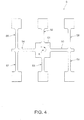
- Fig. 4 is a plan view illustrating an example of an angular velocity sensor provided to the module shown in Figs. 1A and 1B .
- Figs. 5A and 5B are perspective views illustrating a supporting member provided to the module shown in Figs. 1A and 1B .
- Fig. 6 is a transverse cross-sectional view illustrating the module shown in Figs. 1A and 1B .
- Fig. 7 is a cross-sectional view illustrating a module according to a second embodiment of the invention.
- Fig. 8 is a cross-sectional view illustrating a module according to a third embodiment of the invention.
- Fig. 9 is a view illustrating an example of a configuration of an electronic apparatus in which a module is mounted.
- FIGS. 1A and 1B show perspective views illustrating a first embodiment of a module according to the invention
- Figs. 2A and 2B show development views of a mounting substrate provided to the module shown in Figs. 1A and 1B
- Fig. 3 shows a perspective view illustrating a state in which the mounting substrate shown in Figs. 2A and 2B is assembled
- Fig. 4 shows a plan view illustrating an example of an angular velocity sensor provided to the module shown in Figs. 1A and 1B
- Figs. 5A and 5B show perspective views illustrating a supporting member provided to the module shown in Figs. 1A and 1B
- Fig. 6 shows a transverse cross-sectional view illustrating the module shown in Figs.
- the module 1 includes angular velocity sensors 411 to 413 as each sensor device 4, and is a three-axis gyro sensor module that is capable of detecting each angular velocity around an x-axis, a y-axis, and a z-axis that are orthogonal to each other.
- This module 1 is excellent in convenience and may be appropriately used for, for example, a motion trace, a motion tracking, a motion controller, a pedestrian dead reckoning (PDR), or the like.
- the module 1 includes a mounting substrate 2 on which sensor devices 4 such as angular velocity sensors 411 to 413 are mounted, and a supporting member 3 that supports (fixes) the mounting substrate 2.
- the module 1 may further include a casing that accommodates the mounting substrate 2 and the supporting member 3.
- the mounting substrate 2 is a rigid and flexible substrate in which a rigid substrate (hard substrate), which is hard and therefore is difficult to deform, and a flexible substrate, which is soft and therefore is easy to be deformed, are combined.
- a rigid substrate hard substrate
- a flexible substrate which is soft and therefore is easy to be deformed
- a known rigid and flexible substrate in which a hard layer such as a glass epoxy substrate is adhered to both sides of a flexible substrate and this hard layer is used as the rigid substrate may be used.
- Fig. 2A shows a plan view taken when a developed mounting substrate 2 is seen from one face side thereof
- Fig. 2B shows a plan view taken when the developed mounting substrate 2 is seen from a face side opposite to Fig. 2A .
- the mounting substrate 2 includes a first rigid substrate 21, a second rigid substrate 22, a third rigid substrate 23, a fourth rigid substrate 24, and a fifth rigid substrate 25 that are disposed to be spaced from each other, and a flexible substrate 26 that connects these substrates.
- the flexible substrate 26 includes a connecting portion 261 that connects the first rigid substrate 21 and the third rigid substrate 23, a connecting portion 262 that connects the second rigid substrate 22 and the third rigid substrate 23, a connecting portion 263 that connects the third rigid substrate 23 and the fourth rigid substrate 24, and a connecting portion 264 that connects the fourth rigid substrate 24 and the fifth rigid substrate 25.
- hole portions 21a and 21b are formed at both ends of the first rigid substrate 21, respectively, hole portions 22a and 22b are formed at both ends of the second rigid substrate 22, respectively, hole portions 23a and 23b are formed at both ends (both corner portions that are in a diagonal relationship) of the third rigid substrate 23, respectively, hole portions 24a and 24b are formed at both ends (both corner portions that are in a diagonal relationship) of the fourth rigid substrate 24, respectively, hole portions 25a and 25b are formed at both ends of the fifth rigid substrate 25, respectively.
- These hole portions 21a to 25b are used to fix the rigid substrates 21 to 25 to the supporting member 3.
- the hole portions include both a structure that penetrates from one face to another face, and a structure in which an opening is provided on one face and which does not penetrate to another face.
- the respective rigid substrates 21 to 25 and the flexible substrate 26 have a conductor pattern (not shown), and the plurality of sensor devices 4 are electrically connected in an appropriate manner through this conductor pattern.
- a face of each of the rigid substrates 21 to 25, which is shown in Fig. 2A is referred to as a "front-side mounting face", and a face shown in Fig. 2B is referred to as a "rear-side mounting face”.
- the mounting substrate 2 may be deformed into a rectangular parallelepiped shape shown in Fig. 3 by folding the respective connecting portions 261 to 264 of the flexible substrate 26. Specifically, when the connecting portions 261 to 264 are folded (curved) in a manner such that the front-side mounting faces 211 to 251 of the respective rigid substrates 21 to 25 face an inner side, the mounting substrate 2 may be deformed into a rectangular parallelepiped state in which adjacent rigid substrates are orthogonal to each other. In this state, when the third rigid substrate 23 is set as a bottom face, the fourth rigid substrate 24 makes up a top face, and each of the first, second, and fifth rigid substrates 21, 22, and 25 makes up a side face. As shown in Figs. 1A and 1B , the mounting substrate 2 is fixed to the supporting member 3 in this deformed state. In other words, the mounting substrate 2 is designed so as to be deformed into a shape corresponding to the supporting member 3.
- the mounting substrate 2 When the mounting substrate 2 is configured by the above-described rigid and flexible substrate, the mounting substrate 2 may be easily deformed, such that the fixing of the mounting substrate 2 to the supporting member 3 may be simple.
- the respective rigid substrates 21 to 25 are collectively connected, such that in this regard, the fixing of the mounting substrate 2 to the supporting member 3 may be simply and smoothly performed.
- unnecessary vibration of the sensor devices 4 particularly, the angular velocity sensors 411 to 413) may be suppressed and thereby detection accuracy of the module 1 may be improved.
- a ground layer (not shown) is formed in the mounting substrate 2, such that this ground layer exhibits a function of interrupting an external magnetic field. Therefore, in a state shown in Fig. 3 , an effect due to the external magnetic field may be excluded with respect to the sensor devices 4 (sensor devices 4 mounted on the front-side mounting surfaces 211 to 251) that are positioned inside the mounting substrate 2.
- the plurality of the sensor devices 4 are mounted on the mounting substrate 2.
- the three angular velocity sensors 411 to 413 of one-axis detection type, and the acceleration sensor 42 of three-axis detection type are mounted on the mounting substrate 2.
- a power supply circuit 43 that drives the sensor devices 4 (the angular velocity sensors 411 to 413 and the acceleration sensor 42) or the like, an amplifying circuit 44 that amplifies an output signal from the sensor devices 4, an analog/digital converting circuit 45 that converts an analog signal amplified by the amplifying circuit 44 to a digital signal, a microcontroller 46 that performs a desired control, a nonvolatile memory 47 such as an EEPROM, an orientation sensor (magnetic sensor) 48 that detects orientation, and a connector (interface connector) 49 that outputs a signal are mounted on the mounting substrate 2.
- the angular velocity sensor 411 that detects an angular velocity around the x-axis is mounted on the front-side mounting face 211 of the first rigid substrate 21.
- the angular velocity sensor 412 that detects an angular velocity around the y-axis is mounted on the front-side mounting face 221 of the second rigid substrate 22.
- the angular velocity sensor 413 that detects an angular velocity around the z-axis and the acceleration sensor 42 are mounted on the front-side mounting face 231 of the third rigid substrate 23.
- the power supply circuit 43, the amplifying circuit 44, and the analog/digital converting circuit 45 are mounted on the rear-side mounting face 232 of the third rigid substrate 23.
- the angular velocity sensor 413 and the acceleration sensor 42 may be mounted on the rear-side mounting face 232, and the power supply circuit 43, the amplifying circuit 44, and the analog/digital converting circuit 45 may be mounted on the front-side mounting face 231.
- the analog/digital converting circuit 45 has a size larger than that of other electronic components (the power supply circuit 43 and the amplifying circuit 44) that are mounted on the rear-side mounting face 232. Therefore, it is preferable that the analog/digital converting circuit 45 be disposed at a central portion of the rear-side mounting face 232. Due to this configuration, the analog/digital converting circuit 45 may be effectively used as a reinforcing member that augments the strength of the third rigid substrate 23.
- the acceleration sensor 42 be disposed at an edge portion of the front-side mounting face 231 (particularly, in the vicinity of either the hole portion 23a or the hole portion 23b. However, a portion overlapping the bottom face 32 of the supporting member 3 is excluded).
- the third rigid substrate 23 is supported by the bottom face 32 of the supporting member 3 at the edge portion thereof, and is fixed to the supporting member 3 by being screw-coupled thereto with the hole portions 23a and 23b interposed therebetween.
- the edge portion of the third rigid substrate 23 is difficult to deform and the unnecessary vibration is hard to occur. Therefore, when the acceleration sensor 42 is disposed at this place, the acceleration may be detected with relatively high accuracy.
- the microcontroller 46 is mounted on the front-side mounting face 241 of the fourth rigid substrate 24, and the nonvolatile memory 47 and the orientation sensor 48 are mounted on the rear-side mounting face 242.
- the microcontroller 46 has a size larger than that of other electronic component (the nonvolatile memory 47 and the orientation sensor 48) mounted on the fourth rigid substrate 24. Therefore, it is preferable that the microcontroller 46 be disposed at a central portion of the front-side mounting face 241. Due to this configuration, the microcontroller 46 may be effectively used as a reinforcing member that augments the strength of the fourth rigid substrate 24. Therefore, unnecessary vibration caused by bending deformation of the fourth rigid substrate 24 is suppressed, and therefore unnecessary vibration is not transmitted to the angular velocity sensors 411 to 413, and angular velocity detection accuracy by the angular velocity sensors 411 to 413 is raised.
- radiation noise generated from the microcontroller 46 is interrupted by the ground layer of the fourth rigid substrate 24, such that when the orientation sensor 48 is mounted on a mounting face that is opposite to the microcontroller 46, it is possible to prevent the radiation noise from reaching the orientation sensor 48 and having an adverse effect on the orientation sensor 48. Therefore, the detection accuracy of the orientation sensor 48 may be improved.
- a connector 49 is mounted on a rear-side mounting face 252 of the fifth rigid substrate 25.
- analog circuits including the power supply circuit 43, the amplifying circuit 44, and the analog/digital converting circuit 45 are collectively provided in the third rigid substrate 23, a digital circuit including the microcontroller 46 is collectively provided in the fourth rigid substrate 24. Therefore, the propagation of a high-frequency noise generated due to the digital circuit into the analog circuits may be suppressed and therefore excellent reliability and detection accuracy may be exhibited.
- the angular velocity sensors 411 to 413 are not particularly limited as long as the angular velocity may be detected, and an angular velocity sensor of known one axis detection type may be used. As these angular velocity sensors 411 to 413, for example, a sensor provided with a vibrating piece 5 shown in Fig. 4 may be used.
- the vibrating piece 5 is formed of quartz (piezoelectric material).
- the vibrating piece 5 has a base portion 51, a pair of vibrating arms 52 and 53 for detection, which extends in the vertical direction on a plane of paper from both sides of the base portion 51, a pair of connecting arms 54 and 55 that extends in the horizontal direction on the plane of paper from both side of the base portion 51, and respective pairs of vibrating arms 56, 57, 58, and 59 for driving, which extends in the vertical direction on the plane of paper from both sides of distal ends of the respective connecting arms 54 and 55.
- a detection electrode (not shown) is formed on a surface of each of the vibrating arms 52 and 53 for detection
- a driving electrode (not shown) is formed on a surface of each of the vibrating arm 56, 57, 58, and 59 for driving.
- this vibrating piece 5 in a state in which when a voltage is applied to the driving electrode and thereby the vibrating arms 56 and 58 for driving and the vibrating arms 57 and 59 for driving are made to vibrate so as to repeat approaching and separation to and from each other, when an angular velocity ⁇ around a normal line (detection axis) A of the vibrating piece 5 is applied, a Coriolis force is applied to the vibrating piece 5 and the vibration of the vibrating arms 52 and 53 for detection is excited.
- the angular velocity applied to the vibrating piece 5 may be obtained by detecting strain of the vibrating arms 52 and 53 for detection, which is generated due to vibration of the vibrating arms 52 and 53 for detection, using the detection electrode.
- the supporting member 3 has a substantially rectangular parallelepiped shape, and has a top face 31 and a bottom face 32 disposed to be opposite to each other, and four side faces 33, 34, 35, and 36 that connect the top face 31 and the bottom face 32.
- the supporting member 3 at least the bottom face 32, the side face 33, and the side face 34 are accurately formed in order for vertical line thereof to be orthogonal to each other.
- the side face 33, the side face 34, and the bottom face 32 are faces to fix the first to third rigid substrates 21 to 23 on which the angular velocity sensors 411 to 413 are mounted, such that when these three faces are formed to be orthogonal to each other, the angular velocity sensors 411 to 413 may be accurately disposed with respect to the respective axes of the x-axis, the y-axis, and the z-axis. Therefore, according to the module 1, the angular velocity around the respective axes may be detected with high accuracy.
- the side face 33 makes up a fixing face (a first fixing face) that fixes the first rigid substrate 21.
- the first rigid substrate 21 is fixed to the side face 33 in a state the front-side mounting face 211 faces the supporting member 3 side (an inner side).
- the supporting member 3 has two protrusions 332 and 333 that protrude from both end of the side face 33.
- the hole portions 21a and 21b formed in the first rigid substrate 21 engage with the protrusions 332 and 333, and therefore the first rigid substrate 21 is fixed to the side face 33.
- the first rigid substrate 21 may be fixed to the side face 33 while performing positioning of the first rigid substrate 21 with respect to the side face 33.
- the protrusions 332 and 333 are formed on both ends of the side face 33, a spaced distance between the protrusions 332 and 333 is lengthened, and therefore the positioning of the first rigid substrate 21 may be performed with good accuracy.
- first rigid substrate 21 may be strongly fixed to the side face 33. This is true of the second to fifth rigid substrates 22 to 25 described later.
- the supporting member 3 has a relief portion 331 in the side face 33.
- This relief portion 331 is formed in accordance with a position and an exterior appearance of the angular velocity sensor 411, and in a state in which the first rigid substrate 21 is fixed to the side face 33, the angular velocity sensor 411 is accommodated in the relief portion 331. That is, the relief portion 331 may function as a relief portion that prevents the supporting member 3 and the angular velocity sensor 411 from being brought into contact with each other.
- a zenith face (face opposite to a face on which the first rigid substrate 21 is mounted) of the sensor device 4 and a surface of the relief portion 331 of the supporting member may be bonded with adhesive or the like. According to this configuration, the sensor device and the supporting member may be strongly bonded to each other.
- the side face 34 makes up a fixing face (a second fixing face) that fixes the second rigid substrate 22.
- the second rigid substrate 22 is fixed to the side face 34 in a state in which the front-side mounting face 221 faces the supporting member 3 side (an inner side).
- the supporting member 3 has two protrusions 342 and 343 that protrude from both end of the side face 34.
- the hole portions 22a and 22b formed in the second rigid substrate 22 engage with the protrusions 342 and 343, and therefore the second rigid substrate 22 is fixed to the side face 34.
- the supporting member 3 has a relief portion 341 in the side face 34.
- This relief portion 341 is formed in accordance with a position and an exterior appearance of the angular velocity sensor 412, and in a state in which the second rigid substrate 22 is fixed to the side face 34, the angular velocity sensor 412 is accommodated in the relief portion 341. That is, the relief portion 341 may function as a relief portion that prevents the supporting member 3 and the angular velocity sensor 412 from being brought into contact with each other.
- a zenith face (face opposite to a face on which the second rigid substrate 22 is mounted) of the sensor device 4 and a surface of the relief portion 341 of the supporting member may be bonded with adhesive or the like. According to this configuration, the sensor device and the supporting member may be strongly bonded to each other.
- the side face 35 makes up a fixing face that fixes the fifth rigid substrate 25.
- the fifth rigid substrate 25 is fixed to the side face 35 in a state in which the front-side mounting face 251 faces the supporting member 3 side (an inner side). That is, the fifth rigid substrate 25 is fixed to the side face 35 in a state in which the connector 49 is exposed to the outside of the module 1.
- the supporting member 3 has two protrusions 352 and 353 that protrude from both end of the side face 35.
- the hole portions 25a and 25b formed in the fifth rigid substrate 25 engage with the protrusions 352 and 353, and therefore the fifth rigid substrate 25 is fixed to the side face 35.
- the protrusions 342, 343, 352, and 353 are provided on the supporting member 3 side, and the hole portions 22a, 22b, 25a, and 25b are provided on the rigid substrate side, but the protrusion may be provided on the rigid substrate side and the hole portions may be provided on the supporting member side.
- the bottom face 32 makes up a fixing face (a third fixing face) that fixes the third rigid substrate 23.
- the third rigid substrate 23 is fixed to the bottom face 32 in a state in which the front-side mounting face 231 faces the supporting member 3 side (inner side).
- the supporting member 3 is provided with two screw holes 32a and 32b that are formed at two corner portions of the bottom face 32, which are in a diagonal relationship.
- the screw holes 32a and 32b and the hole portions 23a and 23b formed on the third rigid substrate 23 are made to face each other and are screw-coupled with screws 81 and 82, and thereby the third rigid substrate 23 is fixed to the bottom face 32.
- the supporting member 3 is provided with a penetration hole 37 that penetrates through the top face 31 and the bottom face 32, and an exterior appearance has a frame shape.
- the penetration hole 37 functions as an accommodation space of the angular velocity sensor 413 and the acceleration sensor 42, and therefore the penetration hole 37 contributes to reduction in size and thickness of the module.
- the penetration hole 37 also functions as a relief portion that prevents the supporting member 3, and the angular velocity sensor 413 and the acceleration sensor 42 from being brought into contact with each other.
- the top face 31 makes up a fixing face that fixes the fourth rigid substrate 24.
- the fourth rigid substrate 24 is fixed to the top face 31 in a state in which the front-side mounting face 241 faces the supporting member 3 side (inner side).
- the supporting member 3 is provided with two screw holes 31a and 31b that are formed at two corner portions of the top face 31, which are in a diagonal relationship.
- the screw holes 31a and 31b and the hole portions 24a and 24b formed on the fourth rigid substrate 24 are made to face each other and are screw-coupled with screws 83 and 84, and thereby the fourth rigid substrate 24 is fixed to the top face 31.
- the supporting member 3 is provided with the penetration hole 37.
- the microcontroller 46 mounted on the front-side mounting face 241 is accommodated in the penetration hole 37.
- the penetration hole 37 also functions as a relief portion that prevents the supporting member 3 and the microcontroller 46 from being brought into contact with each other.
- a constituent material of the supporting member 3 is not particularly limited, but for example, a hard material is preferable so as to prevent deformation occurred when a pressure is applied from the outside. According to this configuration, a state in which the bottom face 32, the side face 33, and the side face 34 are orthogonal to each other may be reliably maintained and therefore the detection accuracy of the module 1 may be maintained to be high.
- This material is not particularly limited, but as this material, various kinds of metal such as iron, nickel, copper, and aluminum, or alloys or intermetallic compounds containing at least one kind among these kinds of metal, or oxides of these kinds of metal may be exemplified.
- various kinds of metal such as iron, nickel, copper, and aluminum, or alloys or intermetallic compounds containing at least one kind among these kinds of metal, or oxides of these kinds of metal may be exemplified.
- the alloys stainless steel, inconel, and in addition to these, for example, various aluminum-based alloys such as duralumin may be exemplified.
- the supporting member 3 when the supporting member 3 is formed of the metallic material, the following effect may be exhibited. That is, when the supporting member 3 is formed of a material having a high electrical conductivity like a metallic material, for example, radiation noise generated from a microcontroller 46 may be interrupted by the supporting member 3. Therefore, it is possible to prevent this radiation noise from reaching the angular velocity sensors 411 and 412 in the relief portions 331 and 341 and having an adverse effect on the sensors. As a result, the angular velocity may be detected by the angular velocity sensors 411 and 412 with high accuracy.
- polyolefin such as polyethylene, polypropylene, and ethylene-propylene copolymer
- polyester such as polyvinyl chloride, polystyrene, polyamide, polyimide, polycarbonate, poly-(4-methyl pentene-1), ionomer, an acrylic resin, polymethyl methacrylate, acrylonitrile-butadiene-styrene copolymer (ABS resin), acrylonitrile-styrene copolymer (AS resin), butadiene-styrene copolymer, polyethylene telephthalate (PET), and polybutylene telephthalate (PBT), polyether, polyether ketone (PEK), polyether ether ketone (PEEK), polyether imide, polyacetal (POM), polyphenylene oxide, polysulfone, polyether sulfone, polyphenylene sulfide, polyarylate, aromatic poly
- an elastic material that is capable of exhibiting a vibration-proof and vibration isolating function that absorbs unnecessary vibration is preferable.
- this material for example, various rubber materials (particularly, vulcanized rubber) such as natural rubber, isoprene rubber, butadiene rubber, styrene-butadiene rubber, nitrile rubber, chloroprene rubber, butyl rubber, acrylic rubber, ethylene-propylene rubber, silicone rubber, and fluoro-rubber, various kinds of thermoplastic elastomer such as styrene series, polyolefin series, polyvinyl chloride series, polyurethane series, polyester series, polyamide series, polybutadiene series, trans-polyisoprene series, fluoro-rubber series, and chlorinated polyethylene series may be exemplified, and one kind or two kinds or more of these may be combined to be used.
- vibration-isolating steel is preferably used so as to make a hard-to-deform property and the vibration-proof and vibration-isolating function to be compatible with each other.
- the supporting member 3 is provided with three faces that are orthogonal to each other, that is, the bottom face 32, the side face 33, and the side face 34, and the third rigid substrate 23 on which the angular velocity sensor 413 is mounted is fixed to the bottom face 32, the first rigid substrate 21 on which the angular velocity sensor 411 is mounted is fixed to the side face 33, and the second rigid substrate 22 on which the angular velocity sensor 412 is mounted is fixed to the side face 34.
- the three angular velocity sensors 411 to 413 may be disposed to be orthogonal to each other in a simple and reliable manner by only fixing the mounting substrate 2 to the supporting member 3.
- an angular velocity around the x-axis, the y-axis, and the z-axis may be accurately detected. That is, the three angular velocity sensors 411 to 413 may be disposed in a manner such that a detection axis of the angular velocity sensor 411 and the x-axis become parallel with each other, a detection axis of the angular velocity sensor 412 and the y-axis become parallel with each other, and a detection axis of the angular velocity sensor 413 and the z-axis become parallel with each other.
- the angular velocity sensors 411 to 413, and the acceleration sensor 42 are positioned between the mounting substrate 2 and the supporting member 3. Therefore, the angular velocity sensor 411 is prevented from being exposed to the outside of the module 1 by the first rigid substrate 21, the angular velocity sensor 412 is prevented from being exposed to the outside of the module 1 by the second rigid substrate 22, and the angular velocity sensor 413 and the acceleration sensor 42 are prevented from being exposed to the outside of the module 1 by the third rigid substrate 23.
- the angular velocity sensors 411 to 413 and the acceleration sensor 42 do not come into contact with a worker, a manufacturing apparatus, or the like, and therefore these sensors may be effectively prevented from being broken.
- an external magnetic field may be interrupted by the ground layer provided to the mounting substrate 2, such that the angular velocity and the acceleration may be detected by the sensors with good accuracy while the angular velocity sensors 411 to 413 and the acceleration sensor 42 are not affected by the magnetic field.
- the sensor devices 4 are easily broken, and are susceptible to an effect of the magnetic field, such that when the sensor devices 4 are disposed as described above, both reliability and a detection characteristic of the module 1 may be improved.
- the arrangement of the plurality of sensor devices 4 is not particularly limited as long as at least one of the sensor devices 4 is positioned between the mounting substrate 2 and the supporting member 3.
- all of the sensor devices 4 excepting for the connector 49 may be mounted on the front-side mounting faces 211 to 251 of the rigid substrates 21 to 25, respectively, and may be positioned between the mounting substrate 2 and the supporting member 3.
- Fig. 7 shows a cross-sectional view of a module according to a second embodiment of the invention.
- the second embodiment will be mainly described based on a difference with the above-described embodiment, and description with respect to substantially the same configuration as the above-described embodiment will not be repeated.
- the module according to the second embodiment of the invention is substantially the same as the first embodiment except that a configuration of the supporting member is different in each case.
- like reference numerals will be given to like parts having substantially the same functions as the first embodiment.
- a supporting member 3A provided to a module 1A includes a relief portion (concave portion) 381A provided to the top face 31, and a relief portion (concave portion) 382A provided to the bottom face 32.
- the supporting member 3A is provided with an interrupting portion 383A that interrupts on the way the penetration hole 37 provided in the first embodiment, and the supporting member 3A has a cross-section of an H-shape.
- the microcontroller 46 is accommodated in the relief portion 381A.
- the relief portion 381A may also function as a relief portion that prevents the supporting member 3A and the microcontroller 46 from brought into contact with each other.
- this relief portion 381A is formed, an inner space of the supporting member 3A may be effectively utilized and therefore reduction in size (particularly, reduction in thickness) of the module 1 may be promoted.
- the relief portion 382A may function as a relief portion that prevents the supporting member 3A, and the angular velocity sensor 413 and the acceleration sensor 42 from brought into contact with each other.
- this relief portion 382A is formed, an inner space of the supporting member 3A may be effectively utilized and therefore reduction in size (particularly, reduction in thickness) of the module 1 may be promoted.
- a zenith face (face opposite to a face on which the second rigid substrate 22 is mounted) of the sensor device 4 and a surface of the relief portion 341 of the supporting member 3A may be bonded with adhesive or the like. According to this configuration, the sensor device and the supporting member may be strongly bonded to each other.
- the interrupting portion 383A functions as a reinforcing portion that suppresses deformation of the supporting member 3A, such that for example, the supporting member 3A has a configuration that is relatively difficult to deform compared to the supporting member 3 of the above-described first embodiment. Therefore, a state in which the angular velocity sensors 411 to 413 are orthogonal to each other may be maintained in a relatively reliable manner, and therefore the angular velocity sensors may exhibit a relatively excellent detection characteristic.
- the relief portion 381A in which the microcontroller 46 is accommodated is spatially partitioned from the relief portions 331, 341, and 382A in which the angular velocity sensors 411 to 413 are accommodated, respectively. Therefore, for example, when the supporting member 3A is formed of a material having a high electrical conductivity like a metallic material, for example, radiation noise generated from a microcontroller 46 may be interrupted by the supporting member 3A. Therefore, it is possible to prevent this radiation noise from reaching the angular velocity sensors 411 to 413 and having an adverse effect on the sensors. As a result, the angular velocity may be detected by the angular velocity sensors 411 to 413 with high accuracy.
- the first rigid substrate 21 may be supported by using side faces of the third rigid substrate 23 and the fourth rigid substrate 24 without being directly supported by the supporting member 3A.
- a space between the third rigid substrate 23 and the fourth rigid substrate 24 is made to function as a relief portion.
- the rigidity of the supporting member may be raised compared to a configuration in which a relief portion is formed in a side wall of the supporting member 3A.
- this aspect may be applied to another embodiment without being limited to this embodiment.
- Fig. 8 shows a cross-sectional view of a module according to a third embodiment of the invention.
- the third embodiment will be mainly described based on a difference with the above-described embodiments, and description with respect to substantially the same configuration as the above-described embodiments will not be repeated.
- the module according to the third embodiment of the invention is substantially the same as the first embodiment except that a configuration of the supporting member is different in each case.
- like reference numerals will be given to like parts having substantially the same functions as the first embodiment.
- the supporting member 3B provided to the module 1B has a block shape of a substantially rectangular parallelepiped.
- the mounting substrate 2 is disposed so as to cover the outer periphery of the supporting member 3B.
- the mounting substrate 2 is fixed to supporting member 3B through the sensor devices 4 mounted on the front-side mounting faces 211 to 251 of the mounting substrate 2. That is, the first rigid substrate 21 is fixed to the supporting member 3B by fixing the angular velocity sensor 411 mounted on the front-side mounting face 211 to a side face 33B of the supporting member 3B.
- the fixing of the angular velocity sensor 411 to the side face 33B is not particularly limited, and may be performed, for example, using adhesive. This is true of other second to fourth rigid substrates 22 to 24.
- the fifth rigid substrate 25 since the sensor device 4 is not mounted on the front-side mounting face 251, the fifth rigid substrate 25 is directly fixed to the side face 35.
- Fig. 9 shows a view illustrating an example of a configuration of an electronic apparatus 500 in which the module 1 is mounted.
- the electronic apparatus 500 is not particularly limited, and for example, a digital still camera, a video camera, a car navigation system, a cellular phone, a mobile PC, a robot, a gaming machine, a game controller, or the like may be exemplified.
- the electronic apparatus 500 shown in Fig. 9 includes a sensor module 510 provided with the module 1, a processing unit 520, a memory 530, an operation unit 540, and a display portion 550. These are connected to each other by a bus 560.
- the processing unit (CPU, MPU, or the like) 520 performs a control of the sensor module 510 or the like, or an entire control of the electronic apparatus 500.
- the processing unit 520 performs processing on the basis of angular velocity information detected by the sensor module 510.
- the processing unit 520 performs processing for camera shake correction, a posture control, GPS autonomous navigation, or the like on the basis of the angular velocity information.
- the memory 530 stores a control program or various pieces of data, and functions as a work area or a data storing area.
- the operation unit 540 allows a user to operate the electronic apparatus 500.
- the display unit 550 displays various kinds of information to the user.
- the configuration of the mounting substrate is not limited to this, and for example, the mounting substrate may be configured by a plurality of separate rigid substrate (5 sheets of rigid substrate).
- the respective rigid substrates may be fixed to the supporting member and then these rigid substrates may be electrically connected to each other using a connector or the like.
- the supporting member may be formed of a triangular pyramid shape and the mounting substrates may be disposed along side faces of the triangular pyramid.
Landscapes
- Physics & Mathematics (AREA)
- General Physics & Mathematics (AREA)
- Engineering & Computer Science (AREA)
- Radar, Positioning & Navigation (AREA)
- Remote Sensing (AREA)
- Gyroscopes (AREA)
Abstract

Description
- The present invention relates to a module and an electronic apparatus.
- For example, a sensor unit disclosed in
US Patent No. 7040922 is known. The sensor unit disclosed inUS Patent No. 7040922 is provided with a mounting member that has a rectangular parallelepiped shape and three faces orthogonal to each other, and sensor devices mounted on the three faces, respectively. - However, in the sensor unit disclosed in
US Patent No. 7040922 , the sensor devices are exposed to the outside of the sensor unit. Therefore, at the time of manufacturing the sensor units or at the time of confirming operation thereof, and at the time of a process of assembling the sensor units to other electronic apparatus, the sensor units come into direct contact with various apparatuses such as a manufacturing apparatus or with a worker, and therefore the sensor devices may be broken due to the contact and may not exhibit superior detection accuracy. - An advantage of some aspects of the invention is to provide a module and an electronic apparatus that have high reliability and are small in size and thickness, and that are capable of exhibiting superior detection accuracy.
- An aspect of the invention is directed to a module including a sensor device, a mounting substrate that has a plurality of mounting faces, a portion between the mounting faces adjacent to each other being foldable, a supporting member having a plurality of fixing faces, in which the sensor device is mounted on at least one of the mounting faces, each of the mounting faces is disposed along each of the fixing faces, and the sensor device is disposed on the supporting member side.
- According to this configuration, breakage or the like of a sensor device at the time of manufacturing the module or at the time of confirming operation may be prevented, and therefore a module improved in reliability may be provided.
- In the module according to the aspect of the invention, it is preferred that vertical lines of the fixing faces in the supporting member intersect each other.
- In the module according to the aspect of the invention, it is preferred that vertical lines of the fixing faces in the supporting member are orthogonal to each other.
- According to this configuration, when the sensor device is formed of, for example, an angular velocity sensor or an acceleration sensor, and the sensor device is disposed on the fixing faces that intersect each other or are orthogonal to each other, an angular velocity or acceleration around a plurality of axes may be detected with good accuracy.
- In the module according to the aspect of the invention, it is preferred that the sensor device and the fixing face are bonded to each other.
- According to this configuration, bonding between the mounting substrate and the supporting substrate may be strong, and therefore reliability is raised, and the sensor device is prevented from moving due to an external force. As a result, the detection accuracy may be raised.
- In the module according to the aspect of the invention, it is preferred that the supporting member is a rectangular parallelepiped.
- According to this configuration, each face making up the rectangular parallelepiped may be used as each fixing face, and vertical lines of the fixing faces may be easily made to be orthogonal to each other, and therefore when the sensor device is formed of, for example, the angular velocity sensor or the acceleration sensor, and the sensor device is disposed on the fixing faces, an angular velocity or acceleration around a plurality of axes may be detected with good accuracy.
- In the module according to the aspect of the invention, it is preferred that the supporting member is provided with a penetration hole, and at least a part of the sensor device may be accommodated in the penetration hole.
- In the module according to the aspect of the invention, it is preferred that the supporting member is provided with a relief portion, and at least a part of the sensor device is accommodated in the relief portion.
- According to this configuration, at least a part of the sensor device may be accommodated inside the penetration hole, thereby contributing reduction in size and thickness of the module.
- In the module according to the aspect of the invention, it is preferred that a protruding portion is provided to one side of the mounting face and the fixing face, and a hole portion is provided to the other side, and the protruding portion and the hole portion engage with each other.
- According to this configuration, the mounting face and the fixing face may be easily bonded to each other without using an adhesive or the like.
- In the module according to the aspect of the invention, it is preferred that a metallic material is used for the supporting member.
- In this manner, when the supporting member is formed of a material having a high electrical conductivity like a metallic material, for example, radiation noise generated from a microcontroller mounted on the mounting face may be interrupted by the supporting member. Therefore, it is possible to prevent this radiation noise from reaching a sensor device mounted on another mounting face and having an adverse effect on the sensor device.
- In the module according to the aspect of the invention, it is preferred that a hard substrate is used as the mounting faces, and a flexible substrate is connected between the mounting faces.
- According to this configuration, the mounting substrate may be easily deformed, and therefore the fixing of the mounting substrate to the supporting member may be simply performed.
- In the module according to the aspect of the invention, it is preferred that the mounting faces include a first mounting face, a second mounting face, and a third mounting face, and the sensor devices are mounted on the first to third mounting faces, respectively, and detection axes of the sensor devices intersect each other.
- In the module according to the aspect of the invention, it is preferred that the sensor device is an angular velocity sensor or an acceleration sensor.
- According to this configuration, when the sensor device is formed of the angular velocity sensor or the acceleration sensor, and the sensor device is mounted on the first to third mounting faces that intersect each other or are orthogonal to each other, a module that is capable of detecting an angular velocity or acceleration around a plurality of axes may be provided.
- Another aspect of the invention is directed to an electronic apparatus including the module according to the aspect of the invention.
- According to this configuration, an electronic apparatus that is capable of exhibiting excellent reliability may be provided.
- The invention will be described with reference to the accompanying drawings, wherein like numbers reference like elements.
-
Figs. 1A and 1B are perspective views illustrating a first embodiment of a module according to the invention. -
Figs. 2A and 2B are development views of a mounting substrate provided to the module shown inFigs. 1A and 1B . -
Fig. 3 is a perspective view illustrating a state in which the mounting substrate shown inFigs. 2A and 2B is assembled. -
Fig. 4 is a plan view illustrating an example of an angular velocity sensor provided to the module shown inFigs. 1A and 1B . -
Figs. 5A and 5B are perspective views illustrating a supporting member provided to the module shown inFigs. 1A and 1B . -
Fig. 6 is a transverse cross-sectional view illustrating the module shown inFigs. 1A and 1B . -
Fig. 7 is a cross-sectional view illustrating a module according to a second embodiment of the invention. -
Fig. 8 is a cross-sectional view illustrating a module according to a third embodiment of the invention. -
Fig. 9 is a view illustrating an example of a configuration of an electronic apparatus in which a module is mounted. - Hereinafter, a module and an electronic apparatus according to the invention will be described in detail with reference to very suitable embodiment shown in the attached drawings.
- First, a module according to an embodiment of the invention will be described.
-
Figs. 1A and 1B show perspective views illustrating a first embodiment of a module according to the invention,Figs. 2A and 2B show development views of a mounting substrate provided to the module shown inFigs. 1A and 1B ,Fig. 3 shows a perspective view illustrating a state in which the mounting substrate shown inFigs. 2A and 2B is assembled,Fig. 4 shows a plan view illustrating an example of an angular velocity sensor provided to the module shown inFigs. 1A and 1B ,Figs. 5A and 5B show perspective views illustrating a supporting member provided to the module shown inFigs. 1A and 1B , andFig. 6 shows a transverse cross-sectional view illustrating the module shown inFigs. 1A and 1B . In addition, inFigs. 1A and 1B ,Fig. 3 , andFigs. 5A and 5B , an upper side in the drawings is described as "upper", and a lower side in the drawings is described as "lower" in the following description for convenience of description. In addition, as shown inFigs. 1A and 1B , three axes that are orthogonal to each other are referred to as "x-axis", "y-axis", and "z-axis". - The
module 1 according to this embodiment includesangular velocity sensors 411 to 413 as eachsensor device 4, and is a three-axis gyro sensor module that is capable of detecting each angular velocity around an x-axis, a y-axis, and a z-axis that are orthogonal to each other. Thismodule 1 is excellent in convenience and may be appropriately used for, for example, a motion trace, a motion tracking, a motion controller, a pedestrian dead reckoning (PDR), or the like. - As shown in
Figs. 1A and 1B , themodule 1 includes a mountingsubstrate 2 on whichsensor devices 4 such asangular velocity sensors 411 to 413 are mounted, and a supportingmember 3 that supports (fixes) the mountingsubstrate 2. In addition, themodule 1 may further include a casing that accommodates the mountingsubstrate 2 and the supportingmember 3. Hereinafter, these members are sequentially described. - The mounting
substrate 2 is a rigid and flexible substrate in which a rigid substrate (hard substrate), which is hard and therefore is difficult to deform, and a flexible substrate, which is soft and therefore is easy to be deformed, are combined. As this mountingsubstrate 2, for example, a known rigid and flexible substrate in which a hard layer such as a glass epoxy substrate is adhered to both sides of a flexible substrate and this hard layer is used as the rigid substrate may be used. - Here,
Fig. 2A shows a plan view taken when a developed mountingsubstrate 2 is seen from one face side thereof, andFig. 2B shows a plan view taken when the developed mountingsubstrate 2 is seen from a face side opposite toFig. 2A . - As shown in
Figs. 2A and 2B , the mountingsubstrate 2 includes a firstrigid substrate 21, a secondrigid substrate 22, a thirdrigid substrate 23, a fourthrigid substrate 24, and a fifthrigid substrate 25 that are disposed to be spaced from each other, and aflexible substrate 26 that connects these substrates. - The
flexible substrate 26 includes a connectingportion 261 that connects the firstrigid substrate 21 and the thirdrigid substrate 23, a connectingportion 262 that connects the secondrigid substrate 22 and the thirdrigid substrate 23, a connectingportion 263 that connects the thirdrigid substrate 23 and the fourthrigid substrate 24, and a connectingportion 264 that connects the fourthrigid substrate 24 and the fifthrigid substrate 25. - In addition,
hole portions rigid substrate 21, respectively,hole portions rigid substrate 22, respectively,hole portions rigid substrate 23, respectively,hole portions rigid substrate 24, respectively,hole portions rigid substrate 25, respectively. Thesehole portions 21a to 25b are used to fix therigid substrates 21 to 25 to the supportingmember 3. In addition, the hole portions include both a structure that penetrates from one face to another face, and a structure in which an opening is provided on one face and which does not penetrate to another face. - In addition, the respective
rigid substrates 21 to 25 and theflexible substrate 26 have a conductor pattern (not shown), and the plurality ofsensor devices 4 are electrically connected in an appropriate manner through this conductor pattern. - In addition, in the following description, for convenience of description, a face of each of the
rigid substrates 21 to 25, which is shown inFig. 2A , is referred to as a "front-side mounting face", and a face shown inFig. 2B is referred to as a "rear-side mounting face". - The mounting
substrate 2 may be deformed into a rectangular parallelepiped shape shown inFig. 3 by folding the respective connectingportions 261 to 264 of theflexible substrate 26. Specifically, when the connectingportions 261 to 264 are folded (curved) in a manner such that the front-side mounting faces 211 to 251 of the respectiverigid substrates 21 to 25 face an inner side, the mountingsubstrate 2 may be deformed into a rectangular parallelepiped state in which adjacent rigid substrates are orthogonal to each other. In this state, when the thirdrigid substrate 23 is set as a bottom face, the fourthrigid substrate 24 makes up a top face, and each of the first, second, and fifthrigid substrates Figs. 1A and 1B , the mountingsubstrate 2 is fixed to the supportingmember 3 in this deformed state. In other words, the mountingsubstrate 2 is designed so as to be deformed into a shape corresponding to the supportingmember 3. - Hereinbefore, description has been made with respect to the mounting
substrate 2. When the mountingsubstrate 2 is configured by the above-described rigid and flexible substrate, the mountingsubstrate 2 may be easily deformed, such that the fixing of the mountingsubstrate 2 to the supportingmember 3 may be simple. In addition, the respectiverigid substrates 21 to 25 are collectively connected, such that in this regard, the fixing of the mountingsubstrate 2 to the supportingmember 3 may be simply and smoothly performed. In addition, when thesensor devices 4 are mounted on the rigid substrate, unnecessary vibration of the sensor devices 4 (particularly, theangular velocity sensors 411 to 413) may be suppressed and thereby detection accuracy of themodule 1 may be improved. - In addition, a ground layer (not shown) is formed in the mounting
substrate 2, such that this ground layer exhibits a function of interrupting an external magnetic field. Therefore, in a state shown inFig. 3 , an effect due to the external magnetic field may be excluded with respect to the sensor devices 4 (sensor devices 4 mounted on the front-side mounting surfaces 211 to 251) that are positioned inside the mountingsubstrate 2. - As shown in
Figs. 2A and 2B , the plurality of thesensor devices 4 are mounted on the mountingsubstrate 2. - As the
sensor devices 4, the threeangular velocity sensors 411 to 413 of one-axis detection type, and theacceleration sensor 42 of three-axis detection type are mounted on the mountingsubstrate 2. In addition, apower supply circuit 43 that drives the sensor devices 4 (theangular velocity sensors 411 to 413 and the acceleration sensor 42) or the like, an amplifyingcircuit 44 that amplifies an output signal from thesensor devices 4, an analog/digital convertingcircuit 45 that converts an analog signal amplified by the amplifyingcircuit 44 to a digital signal, amicrocontroller 46 that performs a desired control, anonvolatile memory 47 such as an EEPROM, an orientation sensor (magnetic sensor) 48 that detects orientation, and a connector (interface connector) 49 that outputs a signal are mounted on the mountingsubstrate 2. - Hereinafter, disposition of these
sensor devices 4 and the electronic components will be described in detail. - The
angular velocity sensor 411 that detects an angular velocity around the x-axis is mounted on the front-side mounting face 211 of the firstrigid substrate 21. - The
angular velocity sensor 412 that detects an angular velocity around the y-axis is mounted on the front-side mounting face 221 of the secondrigid substrate 22. - The
angular velocity sensor 413 that detects an angular velocity around the z-axis and theacceleration sensor 42 are mounted on the front-side mounting face 231 of the thirdrigid substrate 23. In addition, thepower supply circuit 43, the amplifyingcircuit 44, and the analog/digital convertingcircuit 45 are mounted on the rear-side mounting face 232 of the thirdrigid substrate 23. In addition, theangular velocity sensor 413 and theacceleration sensor 42 may be mounted on the rear-side mounting face 232, and thepower supply circuit 43, the amplifyingcircuit 44, and the analog/digital convertingcircuit 45 may be mounted on the front-side mounting face 231. - Here, the analog/digital converting
circuit 45 has a size larger than that of other electronic components (thepower supply circuit 43 and the amplifying circuit 44) that are mounted on the rear-side mounting face 232. Therefore, it is preferable that the analog/digital convertingcircuit 45 be disposed at a central portion of the rear-side mounting face 232. Due to this configuration, the analog/digital convertingcircuit 45 may be effectively used as a reinforcing member that augments the strength of the thirdrigid substrate 23. Therefore, not-intended vibration caused by bending deformation of the thirdrigid substrate 23 is suppressed, and therefore unnecessary vibration is not transmitted to theangular velocity sensors 411 to 413, and angular velocity detection accuracy by theangular velocity sensors 411 to 413 (particularly, theangular velocity sensor 413 mounted on the third rigid substrate 23) is raised. - In addition, it is preferable that the
acceleration sensor 42 be disposed at an edge portion of the front-side mounting face 231 (particularly, in the vicinity of either thehole portion 23a or thehole portion 23b. However, a portion overlapping thebottom face 32 of the supportingmember 3 is excluded). As described later, the thirdrigid substrate 23 is supported by thebottom face 32 of the supportingmember 3 at the edge portion thereof, and is fixed to the supportingmember 3 by being screw-coupled thereto with thehole portions rigid substrate 23 is difficult to deform and the unnecessary vibration is hard to occur. Therefore, when theacceleration sensor 42 is disposed at this place, the acceleration may be detected with relatively high accuracy. - The
microcontroller 46 is mounted on the front-side mounting face 241 of the fourthrigid substrate 24, and thenonvolatile memory 47 and theorientation sensor 48 are mounted on the rear-side mounting face 242. - Here, the
microcontroller 46 has a size larger than that of other electronic component (thenonvolatile memory 47 and the orientation sensor 48) mounted on the fourthrigid substrate 24. Therefore, it is preferable that themicrocontroller 46 be disposed at a central portion of the front-side mounting face 241. Due to this configuration, themicrocontroller 46 may be effectively used as a reinforcing member that augments the strength of the fourthrigid substrate 24. Therefore, unnecessary vibration caused by bending deformation of the fourthrigid substrate 24 is suppressed, and therefore unnecessary vibration is not transmitted to theangular velocity sensors 411 to 413, and angular velocity detection accuracy by theangular velocity sensors 411 to 413 is raised. - In addition, radiation noise generated from the
microcontroller 46 is interrupted by the ground layer of the fourthrigid substrate 24, such that when theorientation sensor 48 is mounted on a mounting face that is opposite to themicrocontroller 46, it is possible to prevent the radiation noise from reaching theorientation sensor 48 and having an adverse effect on theorientation sensor 48. Therefore, the detection accuracy of theorientation sensor 48 may be improved. - A
connector 49 is mounted on a rear-side mounting face 252 of the fifthrigid substrate 25. - Hereinbefore, the description has been made in detail with respect to the disposition of the
sensor devices 4 and the electronic components. - In the mounting
substrate 2, analog circuits including thepower supply circuit 43, the amplifyingcircuit 44, and the analog/digital convertingcircuit 45 are collectively provided in the thirdrigid substrate 23, a digital circuit including themicrocontroller 46 is collectively provided in the fourthrigid substrate 24. Therefore, the propagation of a high-frequency noise generated due to the digital circuit into the analog circuits may be suppressed and therefore excellent reliability and detection accuracy may be exhibited. - The
angular velocity sensors 411 to 413 are not particularly limited as long as the angular velocity may be detected, and an angular velocity sensor of known one axis detection type may be used. As theseangular velocity sensors 411 to 413, for example, a sensor provided with a vibrating piece 5 shown inFig. 4 may be used. - The vibrating piece 5 is formed of quartz (piezoelectric material). In addition, the vibrating piece 5 has a
base portion 51, a pair of vibratingarms base portion 51, a pair of connectingarms base portion 51, and respective pairs of vibratingarms arms arms arm - In this vibrating piece 5, in a state in which when a voltage is applied to the driving electrode and thereby the vibrating
arms arms arms arms arms - As shown in
Figs. 5A and 5B , andFig. 6 , the supportingmember 3 has a substantially rectangular parallelepiped shape, and has atop face 31 and abottom face 32 disposed to be opposite to each other, and four side faces 33, 34, 35, and 36 that connect thetop face 31 and thebottom face 32. In the supportingmember 3, at least thebottom face 32, theside face 33, and theside face 34 are accurately formed in order for vertical line thereof to be orthogonal to each other. - As described later, the
side face 33, theside face 34, and thebottom face 32 are faces to fix the first to thirdrigid substrates 21 to 23 on which theangular velocity sensors 411 to 413 are mounted, such that when these three faces are formed to be orthogonal to each other, theangular velocity sensors 411 to 413 may be accurately disposed with respect to the respective axes of the x-axis, the y-axis, and the z-axis. Therefore, according to themodule 1, the angular velocity around the respective axes may be detected with high accuracy. - The side face 33 makes up a fixing face (a first fixing face) that fixes the first
rigid substrate 21. The firstrigid substrate 21 is fixed to theside face 33 in a state the front-side mounting face 211 faces the supportingmember 3 side (an inner side). Specifically, the supportingmember 3 has twoprotrusions side face 33. Thehole portions rigid substrate 21 engage with theprotrusions rigid substrate 21 is fixed to theside face 33. - In this manner, by using two
protrusions rigid substrate 21 may be fixed to theside face 33 while performing positioning of the firstrigid substrate 21 with respect to theside face 33. Particularly, when theprotrusions side face 33, a spaced distance between theprotrusions rigid substrate 21 may be performed with good accuracy. - It is preferable that in the fixing of the first
rigid substrate 21 to theside face 33, adhesion using adhesive be used together. Due to this configuration, the firstrigid substrate 21 may be strongly fixed to theside face 33. This is true of the second to fifthrigid substrates 22 to 25 described later. - In addition, the supporting
member 3 has arelief portion 331 in theside face 33. Thisrelief portion 331 is formed in accordance with a position and an exterior appearance of theangular velocity sensor 411, and in a state in which the firstrigid substrate 21 is fixed to theside face 33, theangular velocity sensor 411 is accommodated in therelief portion 331. That is, therelief portion 331 may function as a relief portion that prevents the supportingmember 3 and theangular velocity sensor 411 from being brought into contact with each other. - In addition, a zenith face (face opposite to a face on which the first
rigid substrate 21 is mounted) of thesensor device 4 and a surface of therelief portion 331 of the supporting member may be bonded with adhesive or the like. According to this configuration, the sensor device and the supporting member may be strongly bonded to each other. - When this
relief portion 331 is formed, an inner space of the supportingmember 3 may be effectively utilized and therefore reduction in size of themodule 1 may be promoted. - The side face 34 makes up a fixing face (a second fixing face) that fixes the second
rigid substrate 22. The secondrigid substrate 22 is fixed to theside face 34 in a state in which the front-side mounting face 221 faces the supportingmember 3 side (an inner side). Specifically, the supportingmember 3 has twoprotrusions side face 34. Thehole portions rigid substrate 22 engage with theprotrusions rigid substrate 22 is fixed to theside face 34. - In addition, the supporting
member 3 has arelief portion 341 in theside face 34. Thisrelief portion 341 is formed in accordance with a position and an exterior appearance of theangular velocity sensor 412, and in a state in which the secondrigid substrate 22 is fixed to theside face 34, theangular velocity sensor 412 is accommodated in therelief portion 341. That is, therelief portion 341 may function as a relief portion that prevents the supportingmember 3 and theangular velocity sensor 412 from being brought into contact with each other. - In addition, a zenith face (face opposite to a face on which the second
rigid substrate 22 is mounted) of thesensor device 4 and a surface of therelief portion 341 of the supporting member may be bonded with adhesive or the like. According to this configuration, the sensor device and the supporting member may be strongly bonded to each other. - When this
relief portion 341 is formed, an inner space of the supportingmember 3 may be effectively utilized and therefore the reduction in size of themodule 1 may be promoted. - The side face 35 makes up a fixing face that fixes the fifth
rigid substrate 25. The fifthrigid substrate 25 is fixed to theside face 35 in a state in which the front-side mounting face 251 faces the supportingmember 3 side (an inner side). That is, the fifthrigid substrate 25 is fixed to theside face 35 in a state in which theconnector 49 is exposed to the outside of themodule 1. Specifically, the supportingmember 3 has twoprotrusions side face 35. Thehole portions rigid substrate 25 engage with theprotrusions rigid substrate 25 is fixed to theside face 35. - In addition, in the above description, the
protrusions member 3 side, and thehole portions - The
bottom face 32 makes up a fixing face (a third fixing face) that fixes the thirdrigid substrate 23. The thirdrigid substrate 23 is fixed to thebottom face 32 in a state in which the front-side mounting face 231 faces the supportingmember 3 side (inner side). Specifically, the supportingmember 3 is provided with twoscrew holes bottom face 32, which are in a diagonal relationship. The screw holes 32a and 32b and thehole portions rigid substrate 23 are made to face each other and are screw-coupled withscrews rigid substrate 23 is fixed to thebottom face 32. - In addition, the supporting
member 3 is provided with apenetration hole 37 that penetrates through thetop face 31 and thebottom face 32, and an exterior appearance has a frame shape. In a state in which the thirdrigid substrate 23 is fixed to thebottom face 32, theangular velocity sensor 413 and theacceleration sensor 42 that are mounted on the front-side mounting face 231 are accommodated in thepenetration hole 37. That is, thepenetration hole 37 functions as an accommodation space of theangular velocity sensor 413 and theacceleration sensor 42, and therefore thepenetration hole 37 contributes to reduction in size and thickness of the module. In addition, thepenetration hole 37 also functions as a relief portion that prevents the supportingmember 3, and theangular velocity sensor 413 and theacceleration sensor 42 from being brought into contact with each other. When thepenetration hole 37 is formed, an inner space of the supportingmember 3 may be effectively used, and therefore the reduction in size (reduction in thickness) of themodule 1 may be promoted. - The
top face 31 makes up a fixing face that fixes the fourthrigid substrate 24. The fourthrigid substrate 24 is fixed to thetop face 31 in a state in which the front-side mounting face 241 faces the supportingmember 3 side (inner side). Specifically, the supportingmember 3 is provided with twoscrew holes top face 31, which are in a diagonal relationship. The screw holes 31a and 31b and thehole portions rigid substrate 24 are made to face each other and are screw-coupled withscrews rigid substrate 24 is fixed to thetop face 31. - In addition, as described above, the supporting
member 3 is provided with thepenetration hole 37. In a state in which the fourthrigid substrate 24 is fixed to thetop face 31, themicrocontroller 46 mounted on the front-side mounting face 241 is accommodated in thepenetration hole 37. In addition, thepenetration hole 37 also functions as a relief portion that prevents the supportingmember 3 and themicrocontroller 46 from being brought into contact with each other. When thepenetration hole 37 is formed, an inner space of the supportingmember 3 may be effectively used, and therefore the reduction in size (reduction in thickness) of themodule 1 may be promoted. - Hereinbefore, description has been made in detail with respect to the shape of the supporting
member 3. - In addition, a constituent material of the supporting
member 3 is not particularly limited, but for example, a hard material is preferable so as to prevent deformation occurred when a pressure is applied from the outside. According to this configuration, a state in which thebottom face 32, theside face 33, and theside face 34 are orthogonal to each other may be reliably maintained and therefore the detection accuracy of themodule 1 may be maintained to be high. - This material is not particularly limited, but as this material, various kinds of metal such as iron, nickel, copper, and aluminum, or alloys or intermetallic compounds containing at least one kind among these kinds of metal, or oxides of these kinds of metal may be exemplified. For example, as the alloys, stainless steel, inconel, and in addition to these, for example, various aluminum-based alloys such as duralumin may be exemplified.
- In this manner, when the supporting
member 3 is formed of the metallic material, the following effect may be exhibited. That is, when the supportingmember 3 is formed of a material having a high electrical conductivity like a metallic material, for example, radiation noise generated from amicrocontroller 46 may be interrupted by the supportingmember 3. Therefore, it is possible to prevent this radiation noise from reaching theangular velocity sensors relief portions angular velocity sensors - In addition, as the hard material, in addition to the metallic materials, for example, polyolefin such as polyethylene, polypropylene, and ethylene-propylene copolymer, polyester such as polyvinyl chloride, polystyrene, polyamide, polyimide, polycarbonate, poly-(4-methyl pentene-1), ionomer, an acrylic resin, polymethyl methacrylate, acrylonitrile-butadiene-styrene copolymer (ABS resin), acrylonitrile-styrene copolymer (AS resin), butadiene-styrene copolymer, polyethylene telephthalate (PET), and polybutylene telephthalate (PBT), polyether, polyether ketone (PEK), polyether ether ketone (PEEK), polyether imide, polyacetal (POM), polyphenylene oxide, polysulfone, polyether sulfone, polyphenylene sulfide, polyarylate, aromatic polysester, (liquid crystal polymer), polytetrafluoroethylene, polyvinylidene fluoride, and in addition to these, a fluorine-based resin, an epoxy resin, a phenol resin, a urea resin, a melamine resin, a silicone resin, polyurethane, or the like, or copolymers, blends, polymer alloys, and the like, which contain these as a main component, may be exemplified, and one kind or two kinds or more of these may be combined to be used.
- In addition, as the constituent material of the supporting
member 3, an elastic material that is capable of exhibiting a vibration-proof and vibration isolating function that absorbs unnecessary vibration is preferable. As this material, for example, various rubber materials (particularly, vulcanized rubber) such as natural rubber, isoprene rubber, butadiene rubber, styrene-butadiene rubber, nitrile rubber, chloroprene rubber, butyl rubber, acrylic rubber, ethylene-propylene rubber, silicone rubber, and fluoro-rubber, various kinds of thermoplastic elastomer such as styrene series, polyolefin series, polyvinyl chloride series, polyurethane series, polyester series, polyamide series, polybutadiene series, trans-polyisoprene series, fluoro-rubber series, and chlorinated polyethylene series may be exemplified, and one kind or two kinds or more of these may be combined to be used. - In addition, as the constituent material of the supporting
member 3, vibration-isolating steel is preferably used so as to make a hard-to-deform property and the vibration-proof and vibration-isolating function to be compatible with each other. - Hereinbefore, description has been made with respect to the
module 1. - In this
module 1, the supportingmember 3 is provided with three faces that are orthogonal to each other, that is, thebottom face 32, theside face 33, and theside face 34, and the thirdrigid substrate 23 on which theangular velocity sensor 413 is mounted is fixed to thebottom face 32, the firstrigid substrate 21 on which theangular velocity sensor 411 is mounted is fixed to theside face 33, and the secondrigid substrate 22 on which theangular velocity sensor 412 is mounted is fixed to theside face 34. In this manner, the threeangular velocity sensors 411 to 413 may be disposed to be orthogonal to each other in a simple and reliable manner by only fixing the mountingsubstrate 2 to the supportingmember 3. Therefore, according to themodule 1, an angular velocity around the x-axis, the y-axis, and the z-axis may be accurately detected. That is, the threeangular velocity sensors 411 to 413 may be disposed in a manner such that a detection axis of theangular velocity sensor 411 and the x-axis become parallel with each other, a detection axis of theangular velocity sensor 412 and the y-axis become parallel with each other, and a detection axis of theangular velocity sensor 413 and the z-axis become parallel with each other. - In addition, the
angular velocity sensors 411 to 413, and theacceleration sensor 42 are positioned between the mountingsubstrate 2 and the supportingmember 3. Therefore, theangular velocity sensor 411 is prevented from being exposed to the outside of themodule 1 by the firstrigid substrate 21, theangular velocity sensor 412 is prevented from being exposed to the outside of themodule 1 by the secondrigid substrate 22, and theangular velocity sensor 413 and theacceleration sensor 42 are prevented from being exposed to the outside of themodule 1 by the thirdrigid substrate 23. - According to this arrangement, for example, at the time of manufacturing the
module 1, or at the time of assembling themodule 1 to another electronic apparatus, theangular velocity sensors 411 to 413 and theacceleration sensor 42 do not come into contact with a worker, a manufacturing apparatus, or the like, and therefore these sensors may be effectively prevented from being broken. In addition, as described above, an external magnetic field may be interrupted by the ground layer provided to the mountingsubstrate 2, such that the angular velocity and the acceleration may be detected by the sensors with good accuracy while theangular velocity sensors 411 to 413 and theacceleration sensor 42 are not affected by the magnetic field. - Particularly, the sensor devices 4 (the
angular velocity sensors 411 to 413 and the acceleration sensor 42) are easily broken, and are susceptible to an effect of the magnetic field, such that when thesensor devices 4 are disposed as described above, both reliability and a detection characteristic of themodule 1 may be improved. - In addition, the arrangement of the plurality of
sensor devices 4 is not particularly limited as long as at least one of thesensor devices 4 is positioned between the mountingsubstrate 2 and the supportingmember 3. For example, all of thesensor devices 4 excepting for theconnector 49 may be mounted on the front-side mounting faces 211 to 251 of therigid substrates 21 to 25, respectively, and may be positioned between the mountingsubstrate 2 and the supportingmember 3. -
Fig. 7 shows a cross-sectional view of a module according to a second embodiment of the invention. - Hereinafter, the second embodiment will be mainly described based on a difference with the above-described embodiment, and description with respect to substantially the same configuration as the above-described embodiment will not be repeated.
- The module according to the second embodiment of the invention is substantially the same as the first embodiment except that a configuration of the supporting member is different in each case. In addition, like reference numerals will be given to like parts having substantially the same functions as the first embodiment.
- As shown in
Fig. 7 , a supportingmember 3A provided to a module 1A includes a relief portion (concave portion) 381A provided to thetop face 31, and a relief portion (concave portion) 382A provided to thebottom face 32. In other words, the supportingmember 3A is provided with an interruptingportion 383A that interrupts on the way thepenetration hole 37 provided in the first embodiment, and the supportingmember 3A has a cross-section of an H-shape. - In a state in which the fourth
rigid substrate 24 is fixed to thetop face 31, themicrocontroller 46 is accommodated in therelief portion 381A. In addition, therelief portion 381A may also function as a relief portion that prevents the supportingmember 3A and themicrocontroller 46 from brought into contact with each other. When thisrelief portion 381A is formed, an inner space of the supportingmember 3A may be effectively utilized and therefore reduction in size (particularly, reduction in thickness) of themodule 1 may be promoted. - In addition, in a state in which the third
rigid substrate 23 is fixed to thebottom face 32, theangular velocity sensor 413 and theacceleration sensor 42 are accommodated in therelief portion 382A. That is, therelief portion 382A may function as a relief portion that prevents the supportingmember 3A, and theangular velocity sensor 413 and theacceleration sensor 42 from brought into contact with each other. When thisrelief portion 382A is formed, an inner space of the supportingmember 3A may be effectively utilized and therefore reduction in size (particularly, reduction in thickness) of themodule 1 may be promoted. - In addition, as described above, a zenith face (face opposite to a face on which the second
rigid substrate 22 is mounted) of thesensor device 4 and a surface of therelief portion 341 of the supportingmember 3A may be bonded with adhesive or the like. According to this configuration, the sensor device and the supporting member may be strongly bonded to each other. - In the supporting
member 3A, the interruptingportion 383A functions as a reinforcing portion that suppresses deformation of the supportingmember 3A, such that for example, the supportingmember 3A has a configuration that is relatively difficult to deform compared to the supportingmember 3 of the above-described first embodiment. Therefore, a state in which theangular velocity sensors 411 to 413 are orthogonal to each other may be maintained in a relatively reliable manner, and therefore the angular velocity sensors may exhibit a relatively excellent detection characteristic. - In addition, in this embodiment, the
relief portion 381A in which themicrocontroller 46 is accommodated is spatially partitioned from therelief portions angular velocity sensors 411 to 413 are accommodated, respectively. Therefore, for example, when the supportingmember 3A is formed of a material having a high electrical conductivity like a metallic material, for example, radiation noise generated from amicrocontroller 46 may be interrupted by the supportingmember 3A. Therefore, it is possible to prevent this radiation noise from reaching theangular velocity sensors 411 to 413 and having an adverse effect on the sensors. As a result, the angular velocity may be detected by theangular velocity sensors 411 to 413 with high accuracy. - In addition, as shown in
Fig. 7 , the firstrigid substrate 21 may be supported by using side faces of the thirdrigid substrate 23 and the fourthrigid substrate 24 without being directly supported by the supportingmember 3A. In this aspect, when the length of the thirdrigid substrate 23 and the fourthrigid substrate 24 in the x-axis direction is made to be larger than the length in the x-axis direction of the supportingmember 3A, a space between the thirdrigid substrate 23 and the fourthrigid substrate 24 is made to function as a relief portion. In this manner, the rigidity of the supporting member may be raised compared to a configuration in which a relief portion is formed in a side wall of the supportingmember 3A. In addition, this aspect may be applied to another embodiment without being limited to this embodiment. -
Fig. 8 shows a cross-sectional view of a module according to a third embodiment of the invention. - Hereinafter, the third embodiment will be mainly described based on a difference with the above-described embodiments, and description with respect to substantially the same configuration as the above-described embodiments will not be repeated.
- The module according to the third embodiment of the invention is substantially the same as the first embodiment except that a configuration of the supporting member is different in each case. In addition, like reference numerals will be given to like parts having substantially the same functions as the first embodiment.
- As shown in
Fig. 8 , the supportingmember 3B provided to themodule 1B has a block shape of a substantially rectangular parallelepiped. In addition, the mountingsubstrate 2 is disposed so as to cover the outer periphery of the supportingmember 3B. - In this
module 1B, the mountingsubstrate 2 is fixed to supportingmember 3B through thesensor devices 4 mounted on the front-side mounting faces 211 to 251 of the mountingsubstrate 2. That is, the firstrigid substrate 21 is fixed to the supportingmember 3B by fixing theangular velocity sensor 411 mounted on the front-side mounting face 211 to aside face 33B of the supportingmember 3B. The fixing of theangular velocity sensor 411 to theside face 33B is not particularly limited, and may be performed, for example, using adhesive. This is true of other second to fourthrigid substrates 22 to 24. In addition, in regard to the fifthrigid substrate 25, since thesensor device 4 is not mounted on the front-side mounting face 251, the fifthrigid substrate 25 is directly fixed to theside face 35. - The above-described module 1 (also, 1A and 1B) may be assembled into various electronic apparatus. Hereinafter, an electronic apparatus according to the invention in which the
module 1 is mounted will be described.Fig. 9 shows a view illustrating an example of a configuration of anelectronic apparatus 500 in which themodule 1 is mounted. Theelectronic apparatus 500 is not particularly limited, and for example, a digital still camera, a video camera, a car navigation system, a cellular phone, a mobile PC, a robot, a gaming machine, a game controller, or the like may be exemplified. - The
electronic apparatus 500 shown inFig. 9 includes asensor module 510 provided with themodule 1, aprocessing unit 520, amemory 530, anoperation unit 540, and adisplay portion 550. These are connected to each other by abus 560. The processing unit (CPU, MPU, or the like) 520 performs a control of thesensor module 510 or the like, or an entire control of theelectronic apparatus 500. In addition, theprocessing unit 520 performs processing on the basis of angular velocity information detected by thesensor module 510. For example, theprocessing unit 520 performs processing for camera shake correction, a posture control, GPS autonomous navigation, or the like on the basis of the angular velocity information. Thememory 530 stores a control program or various pieces of data, and functions as a work area or a data storing area. Theoperation unit 540 allows a user to operate theelectronic apparatus 500. Thedisplay unit 550 displays various kinds of information to the user. - Hereinbefore, description has been made with respect to the module and electronic apparatus according to the invention on the basis of embodiments shown in the drawings, but the invention is not limited to these, and configurations of respective portions may be substituted with arbitrary configurations having substantially the same functions. The other arbitrary constituents may be added to the invention. Further, respective embodiments may be appropriately combined.
- In addition, in the above described embodiments, description has been made with respect to a configuration in which the rigid and flexible substrate is used as the mounting substrate, but the configuration of the mounting substrate is not limited to this, and for example, the mounting substrate may be configured by a plurality of separate rigid substrate (5 sheets of rigid substrate). In this case, for example, the respective rigid substrates may be fixed to the supporting member and then these rigid substrates may be electrically connected to each other using a connector or the like.
- In addition, in the above-described embodiments, description has been made with respect to an example in which the vertical lines of the first fixing face and the second fixing face of the supporting member are orthogonal to each other, but it is not necessarily limited to this example. For example, the supporting member may be formed of a triangular pyramid shape and the mounting substrates may be disposed along side faces of the triangular pyramid.
Claims (13)
- A module comprising:a sensor device;a mounting substrate that has a plurality of mounting faces, a portion between the mounting faces adjacent to each other being foldable; anda supporting member having a plurality of fixing faces,wherein the sensor device is mounted on at least one of the mounting faces,each of the mounting faces is disposed along each of the fixing faces, andthe sensor device is disposed on the supporting member side.
- The module according to claim 1,
wherein vertical lines of the fixing faces in the supporting member intersect each other. - The module according to claim 1,
wherein vertical lines of the fixing faces in the supporting member are orthogonal to each other. - The module according to any one of claims 1 to 3,
wherein the sensor device and the fixing face are bonded to each other. - The module according to any one of claims 1 to 4,
wherein the supporting member is a rectangular parallelepiped. - The module according to any one of claims 1 to 4,
wherein the supporting member is provided with a penetration hole, and at least a part of the sensor device is accommodated in the penetration hole. - The module according to any one of claims 1 to 6,
wherein the supporting member is provided with a relief portion, and at least a part of the sensor device is accommodated in the relief portion. - The module according to any one of claims 1 to 7,
wherein a protruding portion is provided to one side of the mounting face and the fixing face, and a hole portion is provided to the other side, and
the protruding portion and the hole portion engage with each other. - The module according to any one of claims 1 to 8,
wherein a metallic material is used for the supporting member. - The module according to any one of claims 1 to 9,
wherein a hard substrate is used as the mounting faces, and
a flexible substrate is connected between the mounting faces. - The module according to any one of claims 1 to 10,
wherein the mounting faces include a first mounting face, a second mounting face, and a third mounting face, and
the sensor device is mounted on each of the first to third mounting faces, and detection axes of the sensor devices intersect each other. - The module according to claim 11,
wherein the sensor device is an angular velocity sensor or an acceleration sensor. - An electronic apparatus comprising:the module according to any one of claims 1 to 12.
Applications Claiming Priority (1)
| Application Number | Priority Date | Filing Date | Title |
|---|---|---|---|
| JP2011122790A JP5935244B2 (en) | 2011-05-31 | 2011-05-31 | Modules and electronics |
Publications (2)
| Publication Number | Publication Date |
|---|---|
| EP2530430A1 true EP2530430A1 (en) | 2012-12-05 |
| EP2530430B1 EP2530430B1 (en) | 2015-04-22 |
Family
ID=46514083
Family Applications (1)
| Application Number | Title | Priority Date | Filing Date |
|---|---|---|---|
| EP20120169761 Active EP2530430B1 (en) | 2011-05-31 | 2012-05-29 | Module and electronic apparatus |
Country Status (4)
| Country | Link |
|---|---|
| US (2) | US9243909B2 (en) |
| EP (1) | EP2530430B1 (en) |
| JP (1) | JP5935244B2 (en) |
| CN (1) | CN102809662A (en) |
Families Citing this family (9)
| Publication number | Priority date | Publication date | Assignee | Title |
|---|---|---|---|---|
| JP2014126495A (en) * | 2012-12-27 | 2014-07-07 | Seiko Epson Corp | Sensor, electronic apparatus, and moving body |
| JP6136402B2 (en) | 2013-03-15 | 2017-05-31 | セイコーエプソン株式会社 | Sensor unit, electronic device, and moving object |
| CN106662446B (en) * | 2014-07-16 | 2019-10-25 | 精工爱普生株式会社 | Sensor unit, electronic equipment and moving body |
| JP6922705B2 (en) * | 2017-12-06 | 2021-08-18 | トヨタ自動車株式会社 | Sensor mounting structure |
| JP2019184452A (en) * | 2018-04-12 | 2019-10-24 | セイコーエプソン株式会社 | Sensor unit and structure monitoring device |
| JP2020101484A (en) * | 2018-12-25 | 2020-07-02 | セイコーエプソン株式会社 | Inertia sensor, electronic apparatus and moving body |
| CN109931485A (en) * | 2019-04-15 | 2019-06-25 | 中国船舶重工集团公司第七0三研究所 | A kind of vibration acceleration sensor bracket of band heat dissipation and heat insulating function |
| CN110793618B (en) * | 2019-10-28 | 2021-10-26 | 浙江优特轴承有限公司 | Method for detecting three-axis vibration of main shaft bearing by using high-frequency single-axis acceleration gauge |
| US11707341B2 (en) * | 2020-03-02 | 2023-07-25 | Biosense Webster (Israel) Ltd. | Jig for assembling a position sensor |
Citations (3)
| Publication number | Priority date | Publication date | Assignee | Title |
|---|---|---|---|---|
| US7040922B2 (en) | 2003-06-05 | 2006-05-09 | Analog Devices, Inc. | Multi-surface mounting member and electronic device |
| US20080100732A1 (en) * | 2006-10-25 | 2008-05-01 | Masanori Minamio | Optical device module, fabrication method thereof, optical device unit and fabrication method thereof |
| US20080117324A1 (en) * | 2006-11-20 | 2008-05-22 | Masanori Minamio | Optical device module and method for fabricating the same |
Family Cites Families (40)
| Publication number | Priority date | Publication date | Assignee | Title |
|---|---|---|---|---|
| US5233871A (en) | 1991-11-01 | 1993-08-10 | Delco Electronics Corporation | Hybrid accelerometer assembly |
| JPH05340960A (en) * | 1992-06-09 | 1993-12-24 | Hitachi Ltd | Multi-dimensional acceleration sensor |
| JP3387199B2 (en) * | 1994-04-21 | 2003-03-17 | 松下電器産業株式会社 | Angular velocity sensor device |
| JPH07306047A (en) | 1994-05-10 | 1995-11-21 | Murata Mfg Co Ltd | Multi-axial detection type vibration gyro |
| JPH09203638A (en) * | 1996-01-25 | 1997-08-05 | Matsushita Electric Ind Co Ltd | Angular-velocity sensor device |
| JP3780086B2 (en) | 1998-01-22 | 2006-05-31 | Necトーキン株式会社 | Attitude angle detector |
| JP3748328B2 (en) | 1998-03-30 | 2006-02-22 | カルソニックカンセイ株式会社 | Sensor |
| JPH11289141A (en) | 1998-04-02 | 1999-10-19 | Toshiba Corp | Circuit board and its manufacture |
| DE19858621C2 (en) | 1998-12-18 | 2001-02-01 | Autoflug Gmbh | Process for improving the measured values of an inertial measuring system |
| JP2000227335A (en) * | 1999-02-04 | 2000-08-15 | Matsushita Electric Ind Co Ltd | Angular velocity sensor |
| JP2001102746A (en) | 1999-09-30 | 2001-04-13 | Sony Corp | Circuit device and manufacturing method thereof |
| JP2002009228A (en) | 2000-06-20 | 2002-01-11 | Seiko Epson Corp | Semiconductor device |
| US6545865B2 (en) | 2001-07-13 | 2003-04-08 | International Business Machines Corporation | Shock mount for a device packaged in a portable cartridge |
| DE10134620A1 (en) | 2001-07-17 | 2003-02-06 | Bosch Gmbh Robert | Multi-axial inertial sensor system has sensor chips associated with sensor axes fixed on wafer plane on several rigid circuit substrates aligned according to sensor axis |
| JP2003107549A (en) | 2001-09-28 | 2003-04-09 | Canon Inc | Mounting device for vibration detecting means, and vibration-proof system |
| JP2005197493A (en) | 2004-01-08 | 2005-07-21 | Ihi Aerospace Co Ltd | Circuit board assembly |
| KR20070114198A (en) | 2005-02-28 | 2007-11-29 | 제이슨 알. 로젠블라트 | Flush mounted assembly for housing an ambient air abnormal condition sensor module |
| JP4751085B2 (en) * | 2005-03-31 | 2011-08-17 | 東京計器株式会社 | Sensor assembly method |
| JP2007057288A (en) | 2005-08-23 | 2007-03-08 | Seiko Epson Corp | Piezoelectric gyroscopic sensor module and electronic device |
| JP4686304B2 (en) | 2005-08-25 | 2011-05-25 | 日信工業株式会社 | Electronic device and method for manufacturing electronic device |
| WO2007116344A1 (en) | 2006-04-07 | 2007-10-18 | Koninklijke Philips Electronics N.V. | Elastically deformable integrated-circuit device |
| US7291023B1 (en) | 2006-11-21 | 2007-11-06 | Autoliv Asp, Inc. | Electric vehicle motion sensor |
| FR2910129B1 (en) * | 2006-12-15 | 2009-07-10 | Skf Ab | INSTRUMENT BEARING BEARING DEVICE |
| US8462109B2 (en) | 2007-01-05 | 2013-06-11 | Invensense, Inc. | Controlling and accessing content using motion processing on mobile devices |
| CN100476358C (en) | 2007-08-06 | 2009-04-08 | 北京航空航天大学 | MEMS gyroscope accurate installation reference component and installation method thereof |
| US20090056446A1 (en) * | 2007-09-05 | 2009-03-05 | Cluff Charles A | Multiple-axis sensor package and method of assembly |
| US7933128B2 (en) | 2007-10-10 | 2011-04-26 | Epson Toyocom Corporation | Electronic device, electronic module, and methods for manufacturing the same |
| US8100010B2 (en) | 2008-04-14 | 2012-01-24 | Honeywell International Inc. | Method and system for forming an electronic assembly having inertial sensors mounted thereto |
| US8037754B2 (en) * | 2008-06-12 | 2011-10-18 | Rosemount Aerospace Inc. | Integrated inertial measurement system and methods of constructing the same |
| US7625245B1 (en) | 2008-07-24 | 2009-12-01 | Lotes Co., Ltd. | Low-profile electrical connector and device thereof |
| JP2010185716A (en) * | 2009-02-10 | 2010-08-26 | Murata Mfg Co Ltd | Angular velocity sensor module |
| JP2010192060A (en) | 2009-02-20 | 2010-09-02 | Cis Electronica Industria & Comercio Ltda | Sensor module and manufacturing method of the same |
| CN101532840B (en) | 2009-03-19 | 2010-12-08 | 浙江大学 | Inertia measurement device for deep-sea inertia navigation |
| JP2010231895A (en) | 2009-03-25 | 2010-10-14 | Panasonic Electric Works Co Ltd | Substrate fixing structure and physical quantity sensor |
| CN102004522A (en) | 2009-08-31 | 2011-04-06 | 鸿富锦精密工业(深圳)有限公司 | Mainboard |
| JP5318720B2 (en) | 2009-09-30 | 2013-10-16 | 富士通テン株式会社 | Electronic control unit |
| US8194409B2 (en) | 2009-11-09 | 2012-06-05 | Tyco Electronics Corporation | Guide frame for a pluggable module |
| JP5302867B2 (en) * | 2009-12-07 | 2013-10-02 | ホシデン株式会社 | Microphone |
| US8368154B2 (en) * | 2010-02-17 | 2013-02-05 | The Regents Of The University Of California | Three dimensional folded MEMS technology for multi-axis sensor systems |
| CN102121829B (en) | 2010-08-09 | 2013-06-12 | 汪滔 | Miniature inertia measurement system |
-
2011
- 2011-05-31 JP JP2011122790A patent/JP5935244B2/en active Active
-
2012
- 2012-05-23 US US13/478,619 patent/US9243909B2/en active Active
- 2012-05-29 EP EP20120169761 patent/EP2530430B1/en active Active
- 2012-05-30 CN CN2012101743765A patent/CN102809662A/en active Pending
-
2015
- 2015-12-16 US US14/971,007 patent/US10072954B2/en active Active
Patent Citations (3)
| Publication number | Priority date | Publication date | Assignee | Title |
|---|---|---|---|---|
| US7040922B2 (en) | 2003-06-05 | 2006-05-09 | Analog Devices, Inc. | Multi-surface mounting member and electronic device |
| US20080100732A1 (en) * | 2006-10-25 | 2008-05-01 | Masanori Minamio | Optical device module, fabrication method thereof, optical device unit and fabrication method thereof |
| US20080117324A1 (en) * | 2006-11-20 | 2008-05-22 | Masanori Minamio | Optical device module and method for fabricating the same |
Also Published As
| Publication number | Publication date |
|---|---|
| US20120304765A1 (en) | 2012-12-06 |
| CN102809662A (en) | 2012-12-05 |
| JP2012251801A (en) | 2012-12-20 |
| JP5935244B2 (en) | 2016-06-15 |
| US9243909B2 (en) | 2016-01-26 |
| US20160097660A1 (en) | 2016-04-07 |
| EP2530430B1 (en) | 2015-04-22 |
| US10072954B2 (en) | 2018-09-11 |
Similar Documents
| Publication | Publication Date | Title |
|---|---|---|
| US10072954B2 (en) | Module and electronic apparatus | |
| US10113875B2 (en) | Module and electronic apparatus | |
| US9052220B2 (en) | Maintaining member, module, and electronic apparatus | |
| US12031847B2 (en) | Sensor device and electronic apparatus | |
| US9541397B2 (en) | Sensor device, and electronic apparatus | |
| US9404755B2 (en) | Sensor having a plurality of mounting boards on which sensor components are mounted, an electronic apparatus having the sensor, and a moving object having the sensor | |
| JP6455567B2 (en) | Sensor devices and electronics | |
| JP5919662B2 (en) | Electronic devices and electronic equipment | |
| JP6806130B2 (en) | Sensor devices and electronics | |
| JP6179579B2 (en) | Sensor devices and electronics | |
| JP6179580B2 (en) | Sensor devices and electronics |
Legal Events
| Date | Code | Title | Description |
|---|---|---|---|
| PUAI | Public reference made under article 153(3) epc to a published international application that has entered the european phase |
Free format text: ORIGINAL CODE: 0009012 |
|
| AK | Designated contracting states |
Kind code of ref document: A1 Designated state(s): AL AT BE BG CH CY CZ DE DK EE ES FI FR GB GR HR HU IE IS IT LI LT LU LV MC MK MT NL NO PL PT RO RS SE SI SK SM TR |
|
| AX | Request for extension of the european patent |
Extension state: BA ME |
|
| 17P | Request for examination filed |
Effective date: 20130516 |
|
| GRAJ | Information related to disapproval of communication of intention to grant by the applicant or resumption of examination proceedings by the epo deleted |
Free format text: ORIGINAL CODE: EPIDOSDIGR1 |
|
| GRAP | Despatch of communication of intention to grant a patent |
Free format text: ORIGINAL CODE: EPIDOSNIGR1 |
|
| GRAP | Despatch of communication of intention to grant a patent |
Free format text: ORIGINAL CODE: EPIDOSNIGR1 |
|
| RIN1 | Information on inventor provided before grant (corrected) |
Inventor name: SAKUMA, MASAYASU Inventor name: CHINO, TAKETO Inventor name: KITAMURA, SHOJIRO Inventor name: KOBAYASHI, YOSHIHIRO Inventor name: OGAMI, MICHIHARU |
|
| INTG | Intention to grant announced |
Effective date: 20141113 |
|
| GRAS | Grant fee paid |
Free format text: ORIGINAL CODE: EPIDOSNIGR3 |
|
| GRAA | (expected) grant |
Free format text: ORIGINAL CODE: 0009210 |
|
| AK | Designated contracting states |
Kind code of ref document: B1 Designated state(s): AL AT BE BG CH CY CZ DE DK EE ES FI FR GB GR HR HU IE IS IT LI LT LU LV MC MK MT NL NO PL PT RO RS SE SI SK SM TR |
|
| REG | Reference to a national code |
Ref country code: GB Ref legal event code: FG4D |
|
| REG | Reference to a national code |
Ref country code: CH Ref legal event code: EP |
|
| REG | Reference to a national code |
Ref country code: AT Ref legal event code: REF Ref document number: 723499 Country of ref document: AT Kind code of ref document: T Effective date: 20150515 |
|
| REG | Reference to a national code |
Ref country code: IE Ref legal event code: FG4D |
|
| REG | Reference to a national code |
Ref country code: DE Ref legal event code: R096 Ref document number: 602012006810 Country of ref document: DE Effective date: 20150603 |
|
| REG | Reference to a national code |
Ref country code: NL Ref legal event code: VDEP Effective date: 20150422 |
|
| REG | Reference to a national code |
Ref country code: AT Ref legal event code: MK05 Ref document number: 723499 Country of ref document: AT Kind code of ref document: T Effective date: 20150422 |
|
| REG | Reference to a national code |
Ref country code: LT Ref legal event code: MG4D |
|
| PG25 | Lapsed in a contracting state [announced via postgrant information from national office to epo] |
Ref country code: NL Free format text: LAPSE BECAUSE OF FAILURE TO SUBMIT A TRANSLATION OF THE DESCRIPTION OR TO PAY THE FEE WITHIN THE PRESCRIBED TIME-LIMIT Effective date: 20150422 |
|
| PG25 | Lapsed in a contracting state [announced via postgrant information from national office to epo] |
Ref country code: ES Free format text: LAPSE BECAUSE OF FAILURE TO SUBMIT A TRANSLATION OF THE DESCRIPTION OR TO PAY THE FEE WITHIN THE PRESCRIBED TIME-LIMIT Effective date: 20150422 Ref country code: NO Free format text: LAPSE BECAUSE OF FAILURE TO SUBMIT A TRANSLATION OF THE DESCRIPTION OR TO PAY THE FEE WITHIN THE PRESCRIBED TIME-LIMIT Effective date: 20150722 Ref country code: HR Free format text: LAPSE BECAUSE OF FAILURE TO SUBMIT A TRANSLATION OF THE DESCRIPTION OR TO PAY THE FEE WITHIN THE PRESCRIBED TIME-LIMIT Effective date: 20150422 Ref country code: LT Free format text: LAPSE BECAUSE OF FAILURE TO SUBMIT A TRANSLATION OF THE DESCRIPTION OR TO PAY THE FEE WITHIN THE PRESCRIBED TIME-LIMIT Effective date: 20150422 Ref country code: FI Free format text: LAPSE BECAUSE OF FAILURE TO SUBMIT A TRANSLATION OF THE DESCRIPTION OR TO PAY THE FEE WITHIN THE PRESCRIBED TIME-LIMIT Effective date: 20150422 Ref country code: PT Free format text: LAPSE BECAUSE OF FAILURE TO SUBMIT A TRANSLATION OF THE DESCRIPTION OR TO PAY THE FEE WITHIN THE PRESCRIBED TIME-LIMIT Effective date: 20150824 |
|
| PG25 | Lapsed in a contracting state [announced via postgrant information from national office to epo] |
Ref country code: RS Free format text: LAPSE BECAUSE OF FAILURE TO SUBMIT A TRANSLATION OF THE DESCRIPTION OR TO PAY THE FEE WITHIN THE PRESCRIBED TIME-LIMIT Effective date: 20150422 Ref country code: LV Free format text: LAPSE BECAUSE OF FAILURE TO SUBMIT A TRANSLATION OF THE DESCRIPTION OR TO PAY THE FEE WITHIN THE PRESCRIBED TIME-LIMIT Effective date: 20150422 Ref country code: AT Free format text: LAPSE BECAUSE OF FAILURE TO SUBMIT A TRANSLATION OF THE DESCRIPTION OR TO PAY THE FEE WITHIN THE PRESCRIBED TIME-LIMIT Effective date: 20150422 Ref country code: GR Free format text: LAPSE BECAUSE OF FAILURE TO SUBMIT A TRANSLATION OF THE DESCRIPTION OR TO PAY THE FEE WITHIN THE PRESCRIBED TIME-LIMIT Effective date: 20150723 Ref country code: IS Free format text: LAPSE BECAUSE OF FAILURE TO SUBMIT A TRANSLATION OF THE DESCRIPTION OR TO PAY THE FEE WITHIN THE PRESCRIBED TIME-LIMIT Effective date: 20150822 |
|
| REG | Reference to a national code |
Ref country code: CH Ref legal event code: PL |
|
| REG | Reference to a national code |
Ref country code: DE Ref legal event code: R097 Ref document number: 602012006810 Country of ref document: DE |
|
| PG25 | Lapsed in a contracting state [announced via postgrant information from national office to epo] |
Ref country code: EE Free format text: LAPSE BECAUSE OF FAILURE TO SUBMIT A TRANSLATION OF THE DESCRIPTION OR TO PAY THE FEE WITHIN THE PRESCRIBED TIME-LIMIT Effective date: 20150422 Ref country code: LI Free format text: LAPSE BECAUSE OF NON-PAYMENT OF DUE FEES Effective date: 20150531 Ref country code: IT Free format text: LAPSE BECAUSE OF FAILURE TO SUBMIT A TRANSLATION OF THE DESCRIPTION OR TO PAY THE FEE WITHIN THE PRESCRIBED TIME-LIMIT Effective date: 20150422 Ref country code: MC Free format text: LAPSE BECAUSE OF FAILURE TO SUBMIT A TRANSLATION OF THE DESCRIPTION OR TO PAY THE FEE WITHIN THE PRESCRIBED TIME-LIMIT Effective date: 20150422 Ref country code: DK Free format text: LAPSE BECAUSE OF FAILURE TO SUBMIT A TRANSLATION OF THE DESCRIPTION OR TO PAY THE FEE WITHIN THE PRESCRIBED TIME-LIMIT Effective date: 20150422 Ref country code: CH Free format text: LAPSE BECAUSE OF NON-PAYMENT OF DUE FEES Effective date: 20150531 |
|
| REG | Reference to a national code |
Ref country code: IE Ref legal event code: MM4A |
|
| PLBE | No opposition filed within time limit |
Free format text: ORIGINAL CODE: 0009261 |
|
| STAA | Information on the status of an ep patent application or granted ep patent |
Free format text: STATUS: NO OPPOSITION FILED WITHIN TIME LIMIT |
|
| PG25 | Lapsed in a contracting state [announced via postgrant information from national office to epo] |
Ref country code: RO Free format text: LAPSE BECAUSE OF NON-PAYMENT OF DUE FEES Effective date: 20150422 Ref country code: CZ Free format text: LAPSE BECAUSE OF FAILURE TO SUBMIT A TRANSLATION OF THE DESCRIPTION OR TO PAY THE FEE WITHIN THE PRESCRIBED TIME-LIMIT Effective date: 20150422 Ref country code: PL Free format text: LAPSE BECAUSE OF FAILURE TO SUBMIT A TRANSLATION OF THE DESCRIPTION OR TO PAY THE FEE WITHIN THE PRESCRIBED TIME-LIMIT Effective date: 20150422 Ref country code: SK Free format text: LAPSE BECAUSE OF FAILURE TO SUBMIT A TRANSLATION OF THE DESCRIPTION OR TO PAY THE FEE WITHIN THE PRESCRIBED TIME-LIMIT Effective date: 20150422 |
|
| 26N | No opposition filed |
Effective date: 20160125 |
|
| REG | Reference to a national code |
Ref country code: FR Ref legal event code: PLFP Year of fee payment: 5 |
|
| PG25 | Lapsed in a contracting state [announced via postgrant information from national office to epo] |
Ref country code: IE Free format text: LAPSE BECAUSE OF NON-PAYMENT OF DUE FEES Effective date: 20150529 |
|
| PG25 | Lapsed in a contracting state [announced via postgrant information from national office to epo] |
Ref country code: SI Free format text: LAPSE BECAUSE OF FAILURE TO SUBMIT A TRANSLATION OF THE DESCRIPTION OR TO PAY THE FEE WITHIN THE PRESCRIBED TIME-LIMIT Effective date: 20150422 |
|
| PG25 | Lapsed in a contracting state [announced via postgrant information from national office to epo] |
Ref country code: BE Free format text: LAPSE BECAUSE OF FAILURE TO SUBMIT A TRANSLATION OF THE DESCRIPTION OR TO PAY THE FEE WITHIN THE PRESCRIBED TIME-LIMIT Effective date: 20150422 |
|
| PG25 | Lapsed in a contracting state [announced via postgrant information from national office to epo] |
Ref country code: MT Free format text: LAPSE BECAUSE OF FAILURE TO SUBMIT A TRANSLATION OF THE DESCRIPTION OR TO PAY THE FEE WITHIN THE PRESCRIBED TIME-LIMIT Effective date: 20150422 |
|
| REG | Reference to a national code |
Ref country code: FR Ref legal event code: PLFP Year of fee payment: 6 |
|
| PG25 | Lapsed in a contracting state [announced via postgrant information from national office to epo] |
Ref country code: HU Free format text: LAPSE BECAUSE OF FAILURE TO SUBMIT A TRANSLATION OF THE DESCRIPTION OR TO PAY THE FEE WITHIN THE PRESCRIBED TIME-LIMIT; INVALID AB INITIO Effective date: 20120529 Ref country code: BG Free format text: LAPSE BECAUSE OF FAILURE TO SUBMIT A TRANSLATION OF THE DESCRIPTION OR TO PAY THE FEE WITHIN THE PRESCRIBED TIME-LIMIT Effective date: 20150422 Ref country code: SM Free format text: LAPSE BECAUSE OF FAILURE TO SUBMIT A TRANSLATION OF THE DESCRIPTION OR TO PAY THE FEE WITHIN THE PRESCRIBED TIME-LIMIT Effective date: 20150422 |
|
| PG25 | Lapsed in a contracting state [announced via postgrant information from national office to epo] |
Ref country code: CY Free format text: LAPSE BECAUSE OF FAILURE TO SUBMIT A TRANSLATION OF THE DESCRIPTION OR TO PAY THE FEE WITHIN THE PRESCRIBED TIME-LIMIT Effective date: 20150422 Ref country code: SE Free format text: LAPSE BECAUSE OF FAILURE TO SUBMIT A TRANSLATION OF THE DESCRIPTION OR TO PAY THE FEE WITHIN THE PRESCRIBED TIME-LIMIT Effective date: 20150422 |
|
| PG25 | Lapsed in a contracting state [announced via postgrant information from national office to epo] |
Ref country code: TR Free format text: LAPSE BECAUSE OF FAILURE TO SUBMIT A TRANSLATION OF THE DESCRIPTION OR TO PAY THE FEE WITHIN THE PRESCRIBED TIME-LIMIT Effective date: 20150422 |
|
| PG25 | Lapsed in a contracting state [announced via postgrant information from national office to epo] |
Ref country code: LU Free format text: LAPSE BECAUSE OF NON-PAYMENT OF DUE FEES Effective date: 20150529 |
|
| REG | Reference to a national code |
Ref country code: FR Ref legal event code: PLFP Year of fee payment: 7 |
|
| PG25 | Lapsed in a contracting state [announced via postgrant information from national office to epo] |
Ref country code: MK Free format text: LAPSE BECAUSE OF FAILURE TO SUBMIT A TRANSLATION OF THE DESCRIPTION OR TO PAY THE FEE WITHIN THE PRESCRIBED TIME-LIMIT Effective date: 20150422 |
|
| PG25 | Lapsed in a contracting state [announced via postgrant information from national office to epo] |
Ref country code: AL Free format text: LAPSE BECAUSE OF FAILURE TO SUBMIT A TRANSLATION OF THE DESCRIPTION OR TO PAY THE FEE WITHIN THE PRESCRIBED TIME-LIMIT Effective date: 20150422 |
|
| PGFP | Annual fee paid to national office [announced via postgrant information from national office to epo] |
Ref country code: FR Payment date: 20210412 Year of fee payment: 10 |
|
| PGFP | Annual fee paid to national office [announced via postgrant information from national office to epo] |
Ref country code: GB Payment date: 20210505 Year of fee payment: 10 |
|
| GBPC | Gb: european patent ceased through non-payment of renewal fee |
Effective date: 20220529 |
|
| PG25 | Lapsed in a contracting state [announced via postgrant information from national office to epo] |
Ref country code: FR Free format text: LAPSE BECAUSE OF NON-PAYMENT OF DUE FEES Effective date: 20220531 |
|
| PG25 | Lapsed in a contracting state [announced via postgrant information from national office to epo] |
Ref country code: GB Free format text: LAPSE BECAUSE OF NON-PAYMENT OF DUE FEES Effective date: 20220529 |
|
| PGFP | Annual fee paid to national office [announced via postgrant information from national office to epo] |
Ref country code: DE Payment date: 20240328 Year of fee payment: 13 |