EP2530265B1 - Dispositif de purification de gaz d'échappement et procédé de purification de gaz d'échappement pour moteur diesel - Google Patents
Dispositif de purification de gaz d'échappement et procédé de purification de gaz d'échappement pour moteur diesel Download PDFInfo
- Publication number
- EP2530265B1 EP2530265B1 EP11734796.3A EP11734796A EP2530265B1 EP 2530265 B1 EP2530265 B1 EP 2530265B1 EP 11734796 A EP11734796 A EP 11734796A EP 2530265 B1 EP2530265 B1 EP 2530265B1
- Authority
- EP
- European Patent Office
- Prior art keywords
- exhaust
- oxidation catalyst
- diesel engine
- disposed
- catalyst
- Prior art date
- Legal status (The legal status is an assumption and is not a legal conclusion. Google has not performed a legal analysis and makes no representation as to the accuracy of the status listed.)
- Not-in-force
Links
Images

Classifications
-
- F—MECHANICAL ENGINEERING; LIGHTING; HEATING; WEAPONS; BLASTING
- F01—MACHINES OR ENGINES IN GENERAL; ENGINE PLANTS IN GENERAL; STEAM ENGINES
- F01N—GAS-FLOW SILENCERS OR EXHAUST APPARATUS FOR MACHINES OR ENGINES IN GENERAL; GAS-FLOW SILENCERS OR EXHAUST APPARATUS FOR INTERNAL COMBUSTION ENGINES
- F01N3/00—Exhaust or silencing apparatus having means for purifying, rendering innocuous, or otherwise treating exhaust
- F01N3/08—Exhaust or silencing apparatus having means for purifying, rendering innocuous, or otherwise treating exhaust for rendering innocuous
- F01N3/10—Exhaust or silencing apparatus having means for purifying, rendering innocuous, or otherwise treating exhaust for rendering innocuous by thermal or catalytic conversion of noxious components of exhaust
- F01N3/18—Exhaust or silencing apparatus having means for purifying, rendering innocuous, or otherwise treating exhaust for rendering innocuous by thermal or catalytic conversion of noxious components of exhaust characterised by methods of operation; Control
- F01N3/20—Exhaust or silencing apparatus having means for purifying, rendering innocuous, or otherwise treating exhaust for rendering innocuous by thermal or catalytic conversion of noxious components of exhaust characterised by methods of operation; Control specially adapted for catalytic conversion ; Methods of operation or control of catalytic converters
- F01N3/2066—Selective catalytic reduction [SCR]
-
- B—PERFORMING OPERATIONS; TRANSPORTING
- B01—PHYSICAL OR CHEMICAL PROCESSES OR APPARATUS IN GENERAL
- B01D—SEPARATION
- B01D53/00—Separation of gases or vapours; Recovering vapours of volatile solvents from gases; Chemical or biological purification of waste gases, e.g. engine exhaust gases, smoke, fumes, flue gases, aerosols
- B01D53/34—Chemical or biological purification of waste gases
- B01D53/92—Chemical or biological purification of waste gases of engine exhaust gases
- B01D53/94—Chemical or biological purification of waste gases of engine exhaust gases by catalytic processes
- B01D53/9459—Removing one or more of nitrogen oxides, carbon monoxide, or hydrocarbons by multiple successive catalytic functions; systems with more than one different function, e.g. zone coated catalysts
- B01D53/9477—Removing one or more of nitrogen oxides, carbon monoxide, or hydrocarbons by multiple successive catalytic functions; systems with more than one different function, e.g. zone coated catalysts with catalysts positioned on separate bricks, e.g. exhaust systems
-
- F—MECHANICAL ENGINEERING; LIGHTING; HEATING; WEAPONS; BLASTING
- F01—MACHINES OR ENGINES IN GENERAL; ENGINE PLANTS IN GENERAL; STEAM ENGINES
- F01N—GAS-FLOW SILENCERS OR EXHAUST APPARATUS FOR MACHINES OR ENGINES IN GENERAL; GAS-FLOW SILENCERS OR EXHAUST APPARATUS FOR INTERNAL COMBUSTION ENGINES
- F01N13/00—Exhaust or silencing apparatus characterised by constructional features ; Exhaust or silencing apparatus, or parts thereof, having pertinent characteristics not provided for in, or of interest apart from, groups F01N1/00 - F01N5/00, F01N9/00, F01N11/00
- F01N13/009—Exhaust or silencing apparatus characterised by constructional features ; Exhaust or silencing apparatus, or parts thereof, having pertinent characteristics not provided for in, or of interest apart from, groups F01N1/00 - F01N5/00, F01N9/00, F01N11/00 having two or more separate purifying devices arranged in series
- F01N13/0093—Exhaust or silencing apparatus characterised by constructional features ; Exhaust or silencing apparatus, or parts thereof, having pertinent characteristics not provided for in, or of interest apart from, groups F01N1/00 - F01N5/00, F01N9/00, F01N11/00 having two or more separate purifying devices arranged in series the purifying devices are of the same type
-
- F—MECHANICAL ENGINEERING; LIGHTING; HEATING; WEAPONS; BLASTING
- F01—MACHINES OR ENGINES IN GENERAL; ENGINE PLANTS IN GENERAL; STEAM ENGINES
- F01N—GAS-FLOW SILENCERS OR EXHAUST APPARATUS FOR MACHINES OR ENGINES IN GENERAL; GAS-FLOW SILENCERS OR EXHAUST APPARATUS FOR INTERNAL COMBUSTION ENGINES
- F01N13/00—Exhaust or silencing apparatus characterised by constructional features ; Exhaust or silencing apparatus, or parts thereof, having pertinent characteristics not provided for in, or of interest apart from, groups F01N1/00 - F01N5/00, F01N9/00, F01N11/00
- F01N13/009—Exhaust or silencing apparatus characterised by constructional features ; Exhaust or silencing apparatus, or parts thereof, having pertinent characteristics not provided for in, or of interest apart from, groups F01N1/00 - F01N5/00, F01N9/00, F01N11/00 having two or more separate purifying devices arranged in series
- F01N13/0097—Exhaust or silencing apparatus characterised by constructional features ; Exhaust or silencing apparatus, or parts thereof, having pertinent characteristics not provided for in, or of interest apart from, groups F01N1/00 - F01N5/00, F01N9/00, F01N11/00 having two or more separate purifying devices arranged in series the purifying devices are arranged in a single housing
-
- F—MECHANICAL ENGINEERING; LIGHTING; HEATING; WEAPONS; BLASTING
- F01—MACHINES OR ENGINES IN GENERAL; ENGINE PLANTS IN GENERAL; STEAM ENGINES
- F01N—GAS-FLOW SILENCERS OR EXHAUST APPARATUS FOR MACHINES OR ENGINES IN GENERAL; GAS-FLOW SILENCERS OR EXHAUST APPARATUS FOR INTERNAL COMBUSTION ENGINES
- F01N3/00—Exhaust or silencing apparatus having means for purifying, rendering innocuous, or otherwise treating exhaust
- F01N3/02—Exhaust or silencing apparatus having means for purifying, rendering innocuous, or otherwise treating exhaust for cooling, or for removing solid constituents of, exhaust
- F01N3/021—Exhaust or silencing apparatus having means for purifying, rendering innocuous, or otherwise treating exhaust for cooling, or for removing solid constituents of, exhaust by means of filters
- F01N3/033—Exhaust or silencing apparatus having means for purifying, rendering innocuous, or otherwise treating exhaust for cooling, or for removing solid constituents of, exhaust by means of filters in combination with other devices
- F01N3/035—Exhaust or silencing apparatus having means for purifying, rendering innocuous, or otherwise treating exhaust for cooling, or for removing solid constituents of, exhaust by means of filters in combination with other devices with catalytic reactors, e.g. catalysed diesel particulate filters
-
- F—MECHANICAL ENGINEERING; LIGHTING; HEATING; WEAPONS; BLASTING
- F01—MACHINES OR ENGINES IN GENERAL; ENGINE PLANTS IN GENERAL; STEAM ENGINES
- F01N—GAS-FLOW SILENCERS OR EXHAUST APPARATUS FOR MACHINES OR ENGINES IN GENERAL; GAS-FLOW SILENCERS OR EXHAUST APPARATUS FOR INTERNAL COMBUSTION ENGINES
- F01N3/00—Exhaust or silencing apparatus having means for purifying, rendering innocuous, or otherwise treating exhaust
- F01N3/08—Exhaust or silencing apparatus having means for purifying, rendering innocuous, or otherwise treating exhaust for rendering innocuous
- F01N3/0807—Exhaust or silencing apparatus having means for purifying, rendering innocuous, or otherwise treating exhaust for rendering innocuous by using absorbents or adsorbents
- F01N3/0828—Exhaust or silencing apparatus having means for purifying, rendering innocuous, or otherwise treating exhaust for rendering innocuous by using absorbents or adsorbents characterised by the absorbed or adsorbed substances
- F01N3/0864—Oxygen
-
- F—MECHANICAL ENGINEERING; LIGHTING; HEATING; WEAPONS; BLASTING
- F01—MACHINES OR ENGINES IN GENERAL; ENGINE PLANTS IN GENERAL; STEAM ENGINES
- F01N—GAS-FLOW SILENCERS OR EXHAUST APPARATUS FOR MACHINES OR ENGINES IN GENERAL; GAS-FLOW SILENCERS OR EXHAUST APPARATUS FOR INTERNAL COMBUSTION ENGINES
- F01N3/00—Exhaust or silencing apparatus having means for purifying, rendering innocuous, or otherwise treating exhaust
- F01N3/08—Exhaust or silencing apparatus having means for purifying, rendering innocuous, or otherwise treating exhaust for rendering innocuous
- F01N3/10—Exhaust or silencing apparatus having means for purifying, rendering innocuous, or otherwise treating exhaust for rendering innocuous by thermal or catalytic conversion of noxious components of exhaust
- F01N3/105—General auxiliary catalysts, e.g. upstream or downstream of the main catalyst
- F01N3/106—Auxiliary oxidation catalysts
-
- F—MECHANICAL ENGINEERING; LIGHTING; HEATING; WEAPONS; BLASTING
- F02—COMBUSTION ENGINES; HOT-GAS OR COMBUSTION-PRODUCT ENGINE PLANTS
- F02B—INTERNAL-COMBUSTION PISTON ENGINES; COMBUSTION ENGINES IN GENERAL
- F02B37/00—Engines characterised by provision of pumps driven at least for part of the time by exhaust
- F02B37/004—Engines characterised by provision of pumps driven at least for part of the time by exhaust with exhaust drives arranged in series
-
- F—MECHANICAL ENGINEERING; LIGHTING; HEATING; WEAPONS; BLASTING
- F02—COMBUSTION ENGINES; HOT-GAS OR COMBUSTION-PRODUCT ENGINE PLANTS
- F02B—INTERNAL-COMBUSTION PISTON ENGINES; COMBUSTION ENGINES IN GENERAL
- F02B37/00—Engines characterised by provision of pumps driven at least for part of the time by exhaust
- F02B37/02—Gas passages between engine outlet and pump drive, e.g. reservoirs
-
- B—PERFORMING OPERATIONS; TRANSPORTING
- B01—PHYSICAL OR CHEMICAL PROCESSES OR APPARATUS IN GENERAL
- B01D—SEPARATION
- B01D2251/00—Reactants
- B01D2251/20—Reductants
- B01D2251/206—Ammonium compounds
- B01D2251/2067—Urea
-
- B—PERFORMING OPERATIONS; TRANSPORTING
- B01—PHYSICAL OR CHEMICAL PROCESSES OR APPARATUS IN GENERAL
- B01D—SEPARATION
- B01D2255/00—Catalysts
- B01D2255/10—Noble metals or compounds thereof
- B01D2255/102—Platinum group metals
- B01D2255/1021—Platinum
-
- B—PERFORMING OPERATIONS; TRANSPORTING
- B01—PHYSICAL OR CHEMICAL PROCESSES OR APPARATUS IN GENERAL
- B01D—SEPARATION
- B01D2255/00—Catalysts
- B01D2255/20—Metals or compounds thereof
- B01D2255/206—Rare earth metals
- B01D2255/2061—Yttrium
-
- B—PERFORMING OPERATIONS; TRANSPORTING
- B01—PHYSICAL OR CHEMICAL PROCESSES OR APPARATUS IN GENERAL
- B01D—SEPARATION
- B01D2255/00—Catalysts
- B01D2255/20—Metals or compounds thereof
- B01D2255/207—Transition metals
- B01D2255/20707—Titanium
-
- B—PERFORMING OPERATIONS; TRANSPORTING
- B01—PHYSICAL OR CHEMICAL PROCESSES OR APPARATUS IN GENERAL
- B01D—SEPARATION
- B01D2255/00—Catalysts
- B01D2255/20—Metals or compounds thereof
- B01D2255/207—Transition metals
- B01D2255/20792—Zinc
-
- B—PERFORMING OPERATIONS; TRANSPORTING
- B01—PHYSICAL OR CHEMICAL PROCESSES OR APPARATUS IN GENERAL
- B01D—SEPARATION
- B01D2255/00—Catalysts
- B01D2255/90—Physical characteristics of catalysts
- B01D2255/908—O2-storage component incorporated in the catalyst
-
- B—PERFORMING OPERATIONS; TRANSPORTING
- B01—PHYSICAL OR CHEMICAL PROCESSES OR APPARATUS IN GENERAL
- B01D—SEPARATION
- B01D2255/00—Catalysts
- B01D2255/90—Physical characteristics of catalysts
- B01D2255/912—HC-storage component incorporated in the catalyst
-
- B—PERFORMING OPERATIONS; TRANSPORTING
- B01—PHYSICAL OR CHEMICAL PROCESSES OR APPARATUS IN GENERAL
- B01D—SEPARATION
- B01D53/00—Separation of gases or vapours; Recovering vapours of volatile solvents from gases; Chemical or biological purification of waste gases, e.g. engine exhaust gases, smoke, fumes, flue gases, aerosols
- B01D53/34—Chemical or biological purification of waste gases
- B01D53/74—General processes for purification of waste gases; Apparatus or devices specially adapted therefor
- B01D53/86—Catalytic processes
- B01D53/90—Injecting reactants
-
- F—MECHANICAL ENGINEERING; LIGHTING; HEATING; WEAPONS; BLASTING
- F01—MACHINES OR ENGINES IN GENERAL; ENGINE PLANTS IN GENERAL; STEAM ENGINES
- F01N—GAS-FLOW SILENCERS OR EXHAUST APPARATUS FOR MACHINES OR ENGINES IN GENERAL; GAS-FLOW SILENCERS OR EXHAUST APPARATUS FOR INTERNAL COMBUSTION ENGINES
- F01N2240/00—Combination or association of two or more different exhaust treating devices, or of at least one such device with an auxiliary device, not covered by indexing codes F01N2230/00 or F01N2250/00, one of the devices being
- F01N2240/20—Combination or association of two or more different exhaust treating devices, or of at least one such device with an auxiliary device, not covered by indexing codes F01N2230/00 or F01N2250/00, one of the devices being a flow director or deflector
-
- F—MECHANICAL ENGINEERING; LIGHTING; HEATING; WEAPONS; BLASTING
- F01—MACHINES OR ENGINES IN GENERAL; ENGINE PLANTS IN GENERAL; STEAM ENGINES
- F01N—GAS-FLOW SILENCERS OR EXHAUST APPARATUS FOR MACHINES OR ENGINES IN GENERAL; GAS-FLOW SILENCERS OR EXHAUST APPARATUS FOR INTERNAL COMBUSTION ENGINES
- F01N2340/00—Dimensional characteristics of the exhaust system, e.g. length, diameter or volume of the apparatus; Spatial arrangements of exhaust apparatuses
- F01N2340/02—Dimensional characteristics of the exhaust system, e.g. length, diameter or volume of the apparatus; Spatial arrangements of exhaust apparatuses characterised by the distance of the apparatus to the engine, or the distance between two exhaust treating apparatuses
-
- F—MECHANICAL ENGINEERING; LIGHTING; HEATING; WEAPONS; BLASTING
- F01—MACHINES OR ENGINES IN GENERAL; ENGINE PLANTS IN GENERAL; STEAM ENGINES
- F01N—GAS-FLOW SILENCERS OR EXHAUST APPARATUS FOR MACHINES OR ENGINES IN GENERAL; GAS-FLOW SILENCERS OR EXHAUST APPARATUS FOR INTERNAL COMBUSTION ENGINES
- F01N2340/00—Dimensional characteristics of the exhaust system, e.g. length, diameter or volume of the apparatus; Spatial arrangements of exhaust apparatuses
- F01N2340/06—Dimensional characteristics of the exhaust system, e.g. length, diameter or volume of the apparatus; Spatial arrangements of exhaust apparatuses characterised by the arrangement of the exhaust apparatus relative to the turbine of a turbocharger
-
- F—MECHANICAL ENGINEERING; LIGHTING; HEATING; WEAPONS; BLASTING
- F01—MACHINES OR ENGINES IN GENERAL; ENGINE PLANTS IN GENERAL; STEAM ENGINES
- F01N—GAS-FLOW SILENCERS OR EXHAUST APPARATUS FOR MACHINES OR ENGINES IN GENERAL; GAS-FLOW SILENCERS OR EXHAUST APPARATUS FOR INTERNAL COMBUSTION ENGINES
- F01N2370/00—Selection of materials for exhaust purification
- F01N2370/02—Selection of materials for exhaust purification used in catalytic reactors
-
- F—MECHANICAL ENGINEERING; LIGHTING; HEATING; WEAPONS; BLASTING
- F01—MACHINES OR ENGINES IN GENERAL; ENGINE PLANTS IN GENERAL; STEAM ENGINES
- F01N—GAS-FLOW SILENCERS OR EXHAUST APPARATUS FOR MACHINES OR ENGINES IN GENERAL; GAS-FLOW SILENCERS OR EXHAUST APPARATUS FOR INTERNAL COMBUSTION ENGINES
- F01N2610/00—Adding substances to exhaust gases
- F01N2610/02—Adding substances to exhaust gases the substance being ammonia or urea
-
- F—MECHANICAL ENGINEERING; LIGHTING; HEATING; WEAPONS; BLASTING
- F01—MACHINES OR ENGINES IN GENERAL; ENGINE PLANTS IN GENERAL; STEAM ENGINES
- F01N—GAS-FLOW SILENCERS OR EXHAUST APPARATUS FOR MACHINES OR ENGINES IN GENERAL; GAS-FLOW SILENCERS OR EXHAUST APPARATUS FOR INTERNAL COMBUSTION ENGINES
- F01N3/00—Exhaust or silencing apparatus having means for purifying, rendering innocuous, or otherwise treating exhaust
- F01N3/08—Exhaust or silencing apparatus having means for purifying, rendering innocuous, or otherwise treating exhaust for rendering innocuous
- F01N3/0807—Exhaust or silencing apparatus having means for purifying, rendering innocuous, or otherwise treating exhaust for rendering innocuous by using absorbents or adsorbents
- F01N3/0814—Exhaust or silencing apparatus having means for purifying, rendering innocuous, or otherwise treating exhaust for rendering innocuous by using absorbents or adsorbents combined with catalytic converters, e.g. NOx absorption/storage reduction catalysts
-
- Y—GENERAL TAGGING OF NEW TECHNOLOGICAL DEVELOPMENTS; GENERAL TAGGING OF CROSS-SECTIONAL TECHNOLOGIES SPANNING OVER SEVERAL SECTIONS OF THE IPC; TECHNICAL SUBJECTS COVERED BY FORMER USPC CROSS-REFERENCE ART COLLECTIONS [XRACs] AND DIGESTS
- Y02—TECHNOLOGIES OR APPLICATIONS FOR MITIGATION OR ADAPTATION AGAINST CLIMATE CHANGE
- Y02T—CLIMATE CHANGE MITIGATION TECHNOLOGIES RELATED TO TRANSPORTATION
- Y02T10/00—Road transport of goods or passengers
- Y02T10/10—Internal combustion engine [ICE] based vehicles
- Y02T10/12—Improving ICE efficiencies
Definitions
- the present invention relates to an exhaust purification device and exhaust purification method for a diesel engine.
- Hazardous substances such as particulate matter (PM), nitrogen oxide (NOx), carbon monoxide (CO), hydrocarbon (HC) and the like are present in the exhaust gas of diesel engines that are installed in vehicles such as trucks, buses and the like.
- Measures taken in recent years to reduce emissions of such hazardous substances from vehicles include measures for reducing the generation itself of hazardous substances, by improving combustion in the diesel engine, and measures for removing, as much as possible, the above-described hazardous substances in the exhaust gas, by arranging a plurality of post-processing units, for instance, a oxidation catalyst (DOC: Diesel Oxidation Catalyst), a diesel particulate filter (DPF: Diesel Particulate Filter), an urea-selective reduction catalyst (urea SCR: Urea-Selective Catalytic Reduction) or a NOx storage-reduction catalyst (LNT: Lean NOx Trap), in an exhaust passage of a diesel engine (Patent Documents 1 and 2).
- DOC Diesel Oxidation Catalyst
- DPF Diesel Particulate Filter
- urea-selective reduction catalyst urea SCR: Urea-Selective Catalytic Reduction
- LNT NOx storage-reduction catalyst
- arranging a plurality of post-processing units in an exhaust passage translates into a greater size of the exhaust purification device that is made up of these post-processing units, and into increased heat capacity of the exhaust purification device.
- a catalyst activation temperature may be difficult to secure in the exhaust purification device having thus increased heat capacity.
- Such an exhaust purification device of greater size is disposed at a distance from the engine, on account of the problem of installation space, and the catalyst activation temperature becomes yet more difficult to secure. As a result, this impairs the hazardous-substance reducing effect that is elicited by each post-processing units of the exhaust purification device.
- the exhaust purification device for a diesel engine includes: an oxidation catalyst that is disposed in an exhaust passage of the diesel engine and purifies CO and HC in exhaust gas; a urea injection nozzle that is disposed in the exhaust passage downstream of the oxidation catalyst and generates ammonia through atomization of urea water into the exhaust gas; a turbine of a turbocharger, this turbine being disposed in the exhaust passage downstream of the urea injection nozzle and accelerating decomposition of urea through agitation of the atomized urea water; a selective reduction catalyst that is disposed in the exhaust passage downstream of the turbine and detoxifies (abates) NOx in the exhaust gas through a reduction reaction with ammonia; and a diesel particulate filter that is disposed in the exhaust passage downstream of the selective reduction catalyst and traps particulate matter in the exhaust gas.
- the diesel particulate filter may be coated with an oxidation catalyst for oxidizing the trapped particulate matter.
- a subsequent-stage oxidation catalyst may be further disposed, in the exhaust passage downstream of the diesel particulate filter, for detoxifying, through oxidation, ammonia that flows out of the diesel particulate filter.
- the oxidation catalyst has a manifold oxidation catalyst disposed at each cylinder portion of an exhaust manifold of the diesel engine, and a pre-turbine oxidation catalyst disposed at a junction portion of the exhaust manifold; the manifold oxidation catalyst being superior to the pre-turbine oxidation catalyst in CO purification.
- the pre-turbine oxidation catalyst may be superior to the manifold oxidation catalyst in HC purification.
- the manifold oxidation catalyst may be a catalyst that includes an oxide semiconductor and an oxide having an oxygen storage material; and the pre-turbine oxidation catalyst may be a metal catalyst.
- the oxide having the oxygen storage material may be an oxide containing Ce; and the oxide semiconductor may be TiO2, ZnO or Y2O3.
- a noble metal may be carried on the oxide having an oxygen storage material.
- An exhaust purification method that is used in the exhaust purification device for a diesel engine described above includes: generating 2NH3+H2SO4 ⁇ (NH4)2SO4 through reaction of ammonia (NH3), generated from urea water atomized out of the urea injection nozzle, and sulfur oxide (SOx) in exhaust gas; generating ammonia (NH3) through thermal decomposition of the (NH4)2SO4 that becomes trapped in the selective reduction catalyst; and using the ammonia (NH3) in a reduction reaction of NOx.
- the exhaust purification device and exhaust purification method for a diesel engine according to the present invention enable effective utilization of exhaust gas heat, and allow reducing the size of the device.
- an intake pipe 3 is connected to an intake manifold 2 and an exhaust pipe 5 is connected to an exhaust manifold 4 of a diesel engine 1.
- the intake manifold 2 and the intake pipe 3 make up an intake passage 6, and the exhaust manifold 4 and the exhaust pipe 5 make up an exhaust passage 7.
- a high-pressure stage turbocharger (high-pressure stage turbo) 8 and a low-pressure stage turbocharger (low-pressure stage turbo) 9 are connected in series to the intake pipe 3 and the exhaust pipe 5.
- a high-pressure stage turbine 12 of the high-pressure stage turbo 8 and a low-pressure stage turbine 13 of the low-pressure stage turbo 9 are disposed in the exhaust pipe 5, and a high-pressure stage compressor 10 of the high-pressure stage turbo 8 and a low-pressure stage compressor 11 of the low-pressure stage turbo 9 are disposed in the intake pipe 3.
- An intercooler 14 is disposed in the intake pipe 3 downstream of the high-pressure stage compressor 10.
- the exhaust manifold 4 and the intake pipe 3 are connected by an EGR pipe 15.
- An EGR valve 16 is disposed in the EGR pipe 15.
- An EGR cooler (not shown) may be provided in the EGR pipe 15.
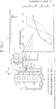
- An exhaust purification device 17a that purifies hazardous substances (PM, NOx, CO, HC and the like) in exhaust gas is disposed in exhaust pipe 5 downstream of the low-pressure stage turbine 13.
- the exhaust purification device 17a is described further on.
- a low-pressure EGR pipe 18 that leads part of the exhaust gas that is directed towards a muffler, not shown, to the intake pipe 3 (to any site from among upstream of the low-pressure stage compressor 11, between the low-pressure stage compressor 11 and the high-pressure stage compressor 10, or upstream of the high-pressure stage compressor 10).
- a low-pressure EGR valve (not shown) is provided in the low-pressure EGR pipe 18. Needless to say, an EGR cooler may also be provided.
- the exhaust purification device 17a comprises a first casing 21a in the interior whereof a oxidation catalyst (DOC) 19a is accommodated, a urea injection nozzle 22a that is disposed in the exhaust pipe 5, downstream of the first casing 21a, and that atomizes urea water into the exhaust pipe 5, and a second casing 25a disposed in the exhaust pipe 5 downstream of the urea injection nozzle 22a and that accommodates, in the interior thereof, an urea-selective reduction catalyst (urea SCR) 23a, a diesel particulate filter (DPF) 20a and a subsequent-stage oxidation catalyst (R-DOC: Rear Diesel Oxidation Catalyst) 24a.
- urea SCR urea-selective reduction catalyst
- DPF diesel particulate filter
- R-DOC Rear Diesel Oxidation Catalyst
- the DOC 19a has the function of purifying, through oxidation, CO and HC in the exhaust gas, and of oxidizing NO.
- the urea injection nozzle 22a has the function of generating ammonia (NH 3 ) through hydrolysis and thermal decomposition of urea water that is atomized into the exhaust pipe 5.
- the urea SCR 23a has the function of detoxifying NOx in the exhaust gas into water and nitrogen, through a reduction reaction with ammonia.
- the DPF 20a has the function of trapping PM in the exhaust gas.
- the R-DOC 24a has the function of detoxifying, through oxidation, the ammonia that flows out of the urea SCR 23a.
- the average inlet temperature of the DOC 19a, the SCR 23a and the DPF 20a was of about 150°C for the DOC 19a, about 140°C for the SCR 23a and about 125°C for the DPF 20a.
- the HC purification rate of the DOC 19a at 150°C is about 10% (likewise the CO purification rate), and the NOx purification rate of the SCR 23a at 140°C is about 40%.
- the average purification rate in the JE05 mode was 50% or less for all HC, CO and NOx.
- a predetermined distance from the urea injection position of the urea injection nozzle 22a up to the inlet of the SCR 23a is required (it is experimentally found that this distance must be 25 cm or longer) in order to cause the urea water that is atomized into the exhaust pipe 5 from the urea injection nozzle 22a to diffuse homogeneously until reaching the SCR 23a, and to enable thereby the urea water to decompose appropriately into ammonia.
- This distance translates into a drop in the temperature of the SCR 23a and into a greater size of the exhaust purification device 17a.
- the exhaust purification device 17 of the diesel engine 1 is provided with: a previous-stage oxidation catalyst (DOC) 19, disposed in the exhaust passage 7 of the diesel engine 1, that purifies CO and HC in the exhaust gas and that oxidizes NO; a urea injection nozzle 22 disposed in the exhaust passage 7, downstream of the DOC 19, for generating ammonia through atomization of urea water into the exhaust gas; the turbine (low-pressure stage turbine) 13, disposed in the exhaust passage 7, downstream of the urea injection nozzle 22, and that accelerates decomposition of urea through agitation of the atomized urea water; a selective reduction catalyst (urea SCR) 23 disposed in the exhaust passage 7, downstream of the low-pressure stage turbine 13, that detoxifies NOx in the exhaust gas through a reduction reaction with ammonia; and a diesel particulate filter (DPF) 20 disposed in the exhaust passage 7, downstream of the urea SCR 23, that traps particulate matter (PM) in the
- DOC previous-stage oxidation catalyst
- Each post-processing unit (DOC 19, urea injection nozzle 22, SCR 23, DPF 20 and R-DOC 24) is explained in detail further on.
- a two-stage turbocharger resulting from connecting, in series, the high-pressure stage turbo 8 and the low-pressure stage turbo 9; the urea injection nozzle 22 is provided between the low-pressure stage turbine 13 and the high-pressure stage turbine 12; and the DOC 19 is disposed upstream of the high-pressure stage turbine 12.
- the configuration may involve a single-stage turbocharger, such that the high-pressure stage turbo 8 is omitted.
- the urea injection nozzle 22 is disposed upstream of the turbine (low-pressure stage turbine 13 in Fig. 2 ) of only one of the turbochargers (low-pressure stage turbo 9 in Fig. 2 ), and the DOC 19 is disposed upstream of the urea injection nozzle 22.
- the urea injection nozzle 22 and the DOC 19 are disposed upstream of the low-pressure stage turbine 13. Therefore, the arrangement position of each post-processing unit (DOC 19, SCR 23, DPF 20, R-DOC 24) can thus be brought closer to the exhaust port of the diesel engine 1 than in the case of the comparative example illustrated in Fig. 1 , where all the post-processing units, including the urea injection nozzle 22 and the DOC 19, are disposed downstream of the low-pressure stage turbine 13. Accordingly, this allows utilizing effectively the heat of the exhaust gas, and makes it easier to maintain the temperature of the post-processing units at the catalyst activation temperature.
- the average inlet temperature of the DOC 19, the SCR 23 and the DPF 20, upon operation of the diesel engine 1 based on a JE05 mode was of about 200°C for the DOC 19, about 175°C for the SCR 23 and about 170°C for the DPF 20.
- the HC purification rate of the DOC 19 at 200°C is about 100% (likewise the CO purification rate), and the NOx purification rate of the SCR 23 at 175°C is about 80%.
- the purification rates of HC, CO and NOx are significantly enhanced vis-à-vis those in the comparative example.
- the DPF 20 is disposed directly below the low-pressure stage turbine 13, with the SCR 23 interposed in between.
- the arrangement position of the DPF 20 lies further upstream, as compared with an instance where the DPF 20a is disposed downstream of the low-pressure stage turbine 13, with the DOC 19a, the urea injection nozzle 22a and the SCR 23a interposed in between, as in the comparative example illustrated in Fig. 1 . Therefore, the temperature of the DPF 20 rises more than in the comparative example, and PM trapped in the DPF 20 can be burned, even with reduced post-injection, or even without post-injection, depending on the operating state. As a result, this allows averting impairment of fuel consumption caused by post-injection, and allows suppressing generation of HC due to post-injection.
- the urea injection nozzle 22 is disposed upstream of the low-pressure stage turbine 13. Therefore, the urea water atomized out of the urea injection nozzle 22 is agitated by the low-pressure stage turbine 13, and diffuses substantially homogeneously downstream of the low-pressure stage turbine 13. Hydrolysis and thermal decomposition of urea are accelerated as a result, and ammonia can be generated appropriately even though the distance from the urea injection position of the urea injection nozzle 22 up to the inlet of the SCR 23 is shorter than in the comparative example.
- the arrangement position of the SCR 23 can be brought closer to the low-pressure stage turbine 13 than is the case in the comparative example. Accordingly, this allows increasing the temperature of the SCR 23 above that in the comparative example, and allows achieving a more compact exhaust purification device 17.
- the DOC 19 has manifold oxidation catalysts (M/F-DOCs) 19x that are disposed in respective cylinder portions of the exhaust manifold 4 of the diesel engine 1, and a pre-turbine oxidation catalyst (P/T-DOC) 19y disposed at the junction portion of the exhaust manifold 4.
- M/F-DOCs 19x used on the upstream side are superior in CO purification to the P/T-DOC 19y on the downstream side.
- the P/T-DOC 19y used in the downstream side is superior in HC purification to the M/F-DOCs 19x on the upstream side. That is because, ordinarily, DOCs afford characteristically better HC adsorption/purification if no CO is present in the exhaust gas, but exhibit no impaired CO adsorption/purification even if HC are present in the exhaust gas.
- the M/F-DOCs 19x are made up of a catalyst that comprises an oxide semiconductor and an oxide having an oxygen storage material (OSC: Oxygen Storage Capacity) that is superior in CO purification (CO adsorption).
- the P/T-DOC 19y is made up of a metal catalyst (for instance, a Pt catalyst) superior in HC purification (HC adsorption). Configuring the DOC 19 as described above allows achieving a catalyst configuration that is superior in low-temperature activity, and makes it possible to reduce the size of the DOC 19 as a whole and to arrange the DOC 19 upstream of the high-pressure stage turbine 12 without difficulty.
- Each M/F-DOC 19x may be a catalyst layer that comprises a catalyst in which there are mixed an oxide semiconductor and an oxide having OSC.
- a catalyst wherein a noble metal catalyst (Pt catalyst or the like) and an HC adsorption material are mixed together may be used in the P/T-DOC 19y.
- An oxide comprising cerium (Ce) (for instance, cerium oxide) may be used in the oxide having OSC, and a noble metal (for instance, Pt) may be carried on the oxide.
- Ce cerium
- Pt platinum
- TiO 2 , ZnO or Y 2 O 3 In the oxide semiconductor there is used TiO 2 , ZnO or Y 2 O 3 .
- the EGR pipe 15 is connected to the exhaust manifold 4 between the M/F-DOCs 19x and the P/T-DOC 19y. After undergoing CO purification by passing through the M/F-DOCs 19x, the exhaust gas passes through the EGR pipe 15 and returns to the intake pipe 3. Unburned substances (SOF component: soluble organic fraction elements) in the returning exhaust gas decrease as a result, and the adverse influence that the SOF exerts on the EGR valve 16 and the EGR cooler (not shown), for instance contamination, clogging and so forth, can be suppressed.
- SOF component soluble organic fraction elements
- the urea injection nozzle 22 is disposed in the exhaust pipe 5 upstream of the low-pressure stage turbine 13. As a result, urea water atomized out of the urea injection nozzle 22 is agitated by the low-pressure stage turbine 13, and diffuses substantially homogeneously downstream of the low-pressure stage turbine 13, so that hydrolysis and thermal decomposition of urea are thus accelerated. As a result, the distance from the urea injection position of the urea injection nozzle 22 up to the inlet of the SCR 23 can be made shorter than in the comparative example, the temperature of the SCR 23 can be increased above that in the comparative example, as already explained, and the exhaust purification device 17 can be made more compact.
- SOx sulfur oxide
- the urea water atomized out of the urea injection nozzle 22 undergoes hydrolysis and thermal decomposition to generate ammonia (NH 3 ), which reacts with SO 4 and so forth in the exhaust gas, to generate 2NH 3 +H 2 SO 4 ⁇ (NH 4 ) 2 SO 4 .
- the generated (NH 4 ) 2 SO 4 is a neutral substance, and hence the problem of corrosion of the exhaust pipe 5 and the low-pressure stage turbine 13 does not occur.
- the (NH 4 ) 2 SO 4 is captured at the SCR 23 directly below the low-pressure stage turbine 13, undergoes thermal decomposition, to generate ammonia (NH 3 ), when at or above a predetermined temperature (for instance, 120°C), and the ammonia (NH 3 ) is used in a reduction reaction of NOx in the SCR 23.
- a predetermined temperature for instance, 120°C
- the SCR 23 is disposed at a position downstream of the low-pressure stage turbine 13, and has the function of detoxifying NOx in the exhaust gas into water and nitrogen, through a reduction reaction with ammonia (NH 3 ).
- the SCR 23, DPF 20 and R-DOC 24 are accommodated in the casing 26 that is formed integrally with the turbine housing of the low-pressure stage turbine 13, but the casing 26 may be separate from the turbine housing, and may be connected to the latter by way of a short exhaust pipe.
- the DPF 20 is disposed at a position downstream of the SCR 23, in the casing 26; herein there is used a DPF 20 (catalyst-carrying DPF) wherein a filter main body is coated with an oxidation catalyst (noble metal catalyst) for burning (oxidizing) the trapped PM.
- a DPF 20 not coated with an oxidation catalyst may be used, however, if an exhaust gas temperature can be secured that allows the PM trapped in the DPF 20 to self-combust.
- the porosity, pore size, and wall thickness are optimized so that the purification characteristics (PM trapping characteristics) are similar to those of conventional products, and in such a manner that pressure loss is small. Thanks to these improvements, a small DPF was used that had a volume 50% or more smaller than that in a conventional product.
- the R-DOC 24 is disposed at a position downstream of the DPF 20, in the casing 26, and has the function of detoxifying, through oxidation, excess ammonia (NH 3 ) that flows through the DPF 20 without having been consumed in the reduction reaction in the SCR 23.
- the ammonia (NH 3 ) that flows out of the SCR 23 without having been consumed in the reduction reaction in the SCR 23 becomes detoxified through oxidation during passage through the catalyst-carrying DPF 20, and hence the R-DOC 24 may be omitted.
- the R-DOC 24 may nonetheless be provided for the sake of thorough detoxification of ammonia (NH 3 ).
- the R-DOC 24 can be omitted if the atomization amount of urea water is controlled, in accordance with the operating state of the diesel engine 1, in such a manner that all the ammonia (NH 3 ) generated from the urea water that is atomized out of the urea injection nozzle 22 is consumed in the SCR 23.
Claims (7)
- Dispositif d'épuration d'échappement pour un moteur diesel (1), comprenant :un catalyseur d'oxydation (19) qui est placé dans un passage d'échappement (7) du moteur diesel (1) et qui purifie le CO et le HC dans le gaz d'échappement ;une buse d'injection d'urée (22) qui est placée dans le passage d'échappement (7), en aval du catalyseur d'oxydation (19) et qui génère de l'ammoniac par atomisation de l'eau d'urée dans le gaz d'échappement ;une turbine (13) d'un turbocompresseur (9), ladite turbine (13) étant placée dans le passage d'échappement, en aval de la buse d'injection d'urée (22) et accélérant la décomposition de l'urée par agitation de l'eau d'urée atomisée ; etun catalyseur de réduction sélective (23) qui est placé dans le passage d'échappement, en aval de la turbine (13) et qui détoxifie le NOx dans le gaz d'échappement par réaction de réduction avec l'ammoniac ;caractérisé par un filtre à particules diesel (20) qui est placé dans le passage d'échappement, en aval du catalyseur de réduction sélective (23) et qui piège les matières particulaires dans le gaz d'échappement, dans lequelle catalyseur d'oxydation (19) possède un catalyseur d'oxydation de collecteur (19x) placé au niveau de chaque partie de cylindre d'un collecteur d'échappement (4) du moteur diesel (1), et un catalyseur d'oxydation avant turbine (19y) placé au niveau d'une partie de jonction du collecteur d'échappement (4),le catalyseur d'oxydation de collecteur (19x) étant supérieur au catalyseur d'oxydation avant turbine (19y) dans l'épuration du CO.
- Dispositif d'épuration d'échappement pour un moteur diesel (1) selon la revendication 1, dans lequel le filtre à particules diesel est revêtu d'un catalyseur d'oxydation destiné à oxyder les matières particulaires piégées.
- Dispositif d'épuration d'échappement pour un moteur diesel selon la revendication 1 ou 2, comprenant en outre un catalyseur d'oxydation d'étage postérieur placé dans le passage d'échappement, en aval du filtre à particules diesel et détoxifiant, par oxydation, l'ammoniac qui sort du filtre à particules diesel.
- Dispositif d'épuration d'échappement pour un moteur diesel selon l'une quelconque des revendications 1 à 3, dans lequel
le catalyseur d'oxydation avant turbine (19y) est supérieur au catalyseur d'oxydation de collecteur (19x) dans l'épuration de HC. - Dispositif d'épuration d'échappement (1) pour un moteur diesel selon la revendication 4, dans lequel
le catalyseur d'oxydation de collecteur (19x) est un catalyseur qui inclut un oxyde semiconducteur et un oxyde avec un matériau de stockage d'oxygène ; et
le catalyseur d'oxydation avant turbine (19y) est un catalyseur métallique. - Dispositif d'épuration d'échappement pour un moteur diesel (1) selon la revendication 5, dans lequel
l'oxyde contenant un matériau de stockage d'oxygène est un oxyde contenant du Ce, et
l'oxyde semiconducteur est TriO2, ZnO ou Y2O3. - Dispositif d'épuration d'échappement (1) pour un moteur diesel selon la revendication 5 ou 6, dans lequel l'oxyde ayant un matériau de stockage d'oxygène est revêtu d'un métal noble.
Applications Claiming Priority (2)
| Application Number | Priority Date | Filing Date | Title |
|---|---|---|---|
| JP2010013414A JP5630025B2 (ja) | 2010-01-25 | 2010-01-25 | ディーゼルエンジンの排気浄化装置及び排気浄化方法 |
| PCT/JP2011/051204 WO2011090190A1 (fr) | 2010-01-25 | 2011-01-24 | Dispositif de purification de gaz d'échappement et procédé de purification de gaz d'échappement pour moteur diesel |
Publications (3)
| Publication Number | Publication Date |
|---|---|
| EP2530265A1 EP2530265A1 (fr) | 2012-12-05 |
| EP2530265A4 EP2530265A4 (fr) | 2015-12-02 |
| EP2530265B1 true EP2530265B1 (fr) | 2018-04-04 |
Family
ID=44306991
Family Applications (1)
| Application Number | Title | Priority Date | Filing Date |
|---|---|---|---|
| EP11734796.3A Not-in-force EP2530265B1 (fr) | 2010-01-25 | 2011-01-24 | Dispositif de purification de gaz d'échappement et procédé de purification de gaz d'échappement pour moteur diesel |
Country Status (5)
| Country | Link |
|---|---|
| US (1) | US20120315204A1 (fr) |
| EP (1) | EP2530265B1 (fr) |
| JP (1) | JP5630025B2 (fr) |
| CN (1) | CN102725486B (fr) |
| WO (1) | WO2011090190A1 (fr) |
Families Citing this family (14)
| Publication number | Priority date | Publication date | Assignee | Title |
|---|---|---|---|---|
| JP5630024B2 (ja) | 2010-01-25 | 2014-11-26 | いすゞ自動車株式会社 | ディーゼルエンジンの排気浄化装置及び排気浄化方法 |
| SE535773C2 (sv) * | 2010-08-13 | 2012-12-11 | Scania Cv Ab | Arrangemang för att spruta in ett reduktionsmedel i en avgasledning hos en förbränningsmotor |
| US9494066B2 (en) * | 2011-06-02 | 2016-11-15 | Toyota Jidosha Kabushiki Kaisha | Control apparatus for an internal combustion engine |
| GB201200784D0 (en) * | 2011-12-12 | 2012-02-29 | Johnson Matthey Plc | Exhaust system for a lean-burn internal combustion engine including SCR catalyst |
| JP5903264B2 (ja) * | 2011-12-22 | 2016-04-13 | 日野自動車株式会社 | 多段過給装置 |
| US9003792B2 (en) * | 2012-04-05 | 2015-04-14 | GM Global Technology Operations LLC | Exhaust aftertreatment and exhaust gas recirculation systems |
| DE102012019948A1 (de) * | 2012-10-11 | 2014-04-17 | Man Diesel & Turbo Se | Abgasnachbehandlungssystem und Verfahren zur Abgasnachbehandlung |
| JP6024694B2 (ja) * | 2014-03-25 | 2016-11-16 | トヨタ自動車株式会社 | 過給機を備えた内燃機関の排気浄化システム |
| CN112901319B (zh) * | 2014-12-31 | 2022-12-16 | 康明斯排放处理公司 | 紧密联接的单模块后处理系统 |
| KR102468987B1 (ko) * | 2015-02-20 | 2022-11-22 | 존슨 맛쎄이 퍼블릭 리미티드 컴파니 | 발전 장치를 위한 배기 시스템 |
| US10022667B2 (en) * | 2016-07-29 | 2018-07-17 | Cummins Inc. | Systems and methods for increasing nitrogen dioxide fraction in exhaust gas at low temperature |
| JP2018135078A (ja) * | 2017-02-24 | 2018-08-30 | トヨタ自動車株式会社 | ハイブリッド自動車 |
| US10724412B2 (en) | 2017-12-20 | 2020-07-28 | Cnh Industrial America Llc | Exhaust system for a work vehicle |
| KR102028423B1 (ko) * | 2018-03-15 | 2019-10-04 | 주식회사 이알인터내셔널 | 운행차용 선택적 환원촉매 시스템 |
Family Cites Families (23)
| Publication number | Priority date | Publication date | Assignee | Title |
|---|---|---|---|---|
| JPS5817644B2 (ja) * | 1977-12-23 | 1983-04-08 | 株式会社日立製作所 | 窒素酸化物を含む排ガスの処理法 |
| GB9919013D0 (en) * | 1999-08-13 | 1999-10-13 | Johnson Matthey Plc | Reactor |
| JP2004100489A (ja) * | 2002-09-05 | 2004-04-02 | Hino Motors Ltd | 排気白煙化防止装置 |
| US6871490B2 (en) * | 2002-12-19 | 2005-03-29 | Caterpillar Inc | Emissions control system for increasing selective catalytic reduction efficiency |
| JP2004204699A (ja) * | 2002-12-24 | 2004-07-22 | Hino Motors Ltd | 排気浄化装置 |
| JP2004239109A (ja) * | 2003-02-04 | 2004-08-26 | Hino Motors Ltd | エンジンの排ガス浄化装置 |
| DE10321105A1 (de) * | 2003-05-09 | 2004-12-02 | Emitec Gesellschaft Für Emissionstechnologie Mbh | Regeneration einer Partikelfalle |
| JP2005061362A (ja) * | 2003-08-19 | 2005-03-10 | Hino Motors Ltd | 排気浄化装置 |
| DE202005001257U1 (de) * | 2004-09-17 | 2005-04-07 | Arvinmeritor Emissions Tech | Abgasanlage eines Kfzs mit Dieselmotor |
| US20060112678A1 (en) * | 2004-11-04 | 2006-06-01 | Eaton Corporation | Multiple reactant multiple catalyst selective catalytic reduction for NOx abatement in internal combustion engines |
| JP4067025B2 (ja) * | 2006-09-11 | 2008-03-26 | いすゞ自動車株式会社 | 多段ターボチャージャの制御装置 |
| JP4197029B2 (ja) * | 2006-11-02 | 2008-12-17 | いすゞ自動車株式会社 | 排気ガス浄化触媒、排気ガス浄化システム及び排気ガス浄化方法 |
| US20080236149A1 (en) * | 2007-04-02 | 2008-10-02 | Ronald Kyle | Combination exhaust gas turbine-catalytic converter |
| JP4592816B2 (ja) * | 2007-05-03 | 2010-12-08 | エムエーエヌ・ディーゼル・アンド・ターボ・フィリアル・アフ・エムエーエヌ・ディーゼル・アンド・ターボ・エスイー・ティスクランド | Scr反応器を備える大型ターボ過給型ディーゼルエンジン |
| JP5110954B2 (ja) * | 2007-05-09 | 2012-12-26 | エヌ・イーケムキャット株式会社 | 選択還元型触媒を用いた排気ガス浄化触媒装置並びに排気ガス浄化方法 |
| JP4811366B2 (ja) * | 2007-07-20 | 2011-11-09 | トヨタ自動車株式会社 | 内燃機関の排気制御装置 |
| US8591848B2 (en) * | 2007-11-09 | 2013-11-26 | Fuel Tech, Inc. | Selective catalytic NOx reduction process and control system |
| US8176729B2 (en) * | 2008-03-06 | 2012-05-15 | GM Global Technology Operations LLC | Perturbation control strategy for low-temperature urea SCR NOx reduction |
| US7971430B2 (en) * | 2008-04-04 | 2011-07-05 | Ford Global Technologies, Llc | Diesel turbine SCR catalyst |
| JP2009257226A (ja) | 2008-04-17 | 2009-11-05 | Toyota Motor Corp | 内燃機関の排気浄化装置 |
| JP5222616B2 (ja) | 2008-04-23 | 2013-06-26 | 日野自動車株式会社 | 排気浄化装置 |
| EP3473825A1 (fr) * | 2008-06-27 | 2019-04-24 | Umicore Ag & Co. Kg | Procédé et dispositif de nettoyage de gaz d'échappement de moteurs diesel |
| FR2937374A3 (fr) * | 2008-10-21 | 2010-04-23 | Renault Sas | Echappement de moteur a combustion interne comportant un injecteur de reducteur et procede associe |
-
2010
- 2010-01-25 JP JP2010013414A patent/JP5630025B2/ja not_active Expired - Fee Related
-
2011
- 2011-01-24 US US13/574,431 patent/US20120315204A1/en not_active Abandoned
- 2011-01-24 WO PCT/JP2011/051204 patent/WO2011090190A1/fr active Application Filing
- 2011-01-24 EP EP11734796.3A patent/EP2530265B1/fr not_active Not-in-force
- 2011-01-24 CN CN201180007039.0A patent/CN102725486B/zh not_active Expired - Fee Related
Non-Patent Citations (1)
| Title |
|---|
| None * |
Also Published As
| Publication number | Publication date |
|---|---|
| JP5630025B2 (ja) | 2014-11-26 |
| CN102725486B (zh) | 2014-09-03 |
| CN102725486A (zh) | 2012-10-10 |
| EP2530265A1 (fr) | 2012-12-05 |
| EP2530265A4 (fr) | 2015-12-02 |
| US20120315204A1 (en) | 2012-12-13 |
| JP2011149401A (ja) | 2011-08-04 |
| WO2011090190A1 (fr) | 2011-07-28 |
Similar Documents
| Publication | Publication Date | Title |
|---|---|---|
| EP2530268B1 (fr) | Dispositif de purification de gaz d'échappement et procédé de purification de gaz d'échappement pour moteur diesel | |
| EP2530265B1 (fr) | Dispositif de purification de gaz d'échappement et procédé de purification de gaz d'échappement pour moteur diesel | |
| KR101631149B1 (ko) | 암모니아 분해 모듈을 가지는 디젤엔진 배기가스 배출장치 | |
| JP6074912B2 (ja) | 排気ガス浄化システム及び排気ガス浄化方法 | |
| KR101509689B1 (ko) | 배기 가스 정화 장치 및 이를 포함하는 배기 장치 | |
| EP2683468B1 (fr) | Système d'échappement contenant un catalyseur de déplacement d'ammoniac dans un circuit egr | |
| WO2013172215A1 (fr) | Système de purification de gaz d'échappement et procédé de purification de gaz d'échappement | |
| EP2230001A1 (fr) | Traitement de gaz d'échappement | |
| US20090205325A1 (en) | Compact Exhaust Gas Aftertreatment System | |
| US9957866B2 (en) | Exhaust treatment apparatus and method | |
| JP2013189900A (ja) | 排気ガス浄化装置 | |
| US20130232953A1 (en) | Exhaust-gas aftertreatment system and method for exhaust-gas aftertreatment | |
| JP2013142363A (ja) | ディーゼルエンジンの排気ガス浄化装置 | |
| CN109891064B (zh) | 废气后处理系统 | |
| US20080041041A1 (en) | Method for Exhaust-Gas Treatment for Diesel Engines or the Like, and Apparatus for Implementing This Method | |
| US10138779B2 (en) | Selective catalytic reduction filter devices having NOx storage capabilities | |
| JP2012159054A (ja) | 内燃機関の排気ガス浄化システム | |
| KR102431789B1 (ko) | 노후 경유차 배기가스 후처리 시스템의 환원제 분사 시스템 | |
| EP2404045A1 (fr) | Dispositif et procede de traitement des oxydes d'azote contenus dans des gaz d'echappement |
Legal Events
| Date | Code | Title | Description |
|---|---|---|---|
| PUAI | Public reference made under article 153(3) epc to a published international application that has entered the european phase |
Free format text: ORIGINAL CODE: 0009012 |
|
| 17P | Request for examination filed |
Effective date: 20120803 |
|
| AK | Designated contracting states |
Kind code of ref document: A1 Designated state(s): AL AT BE BG CH CY CZ DE DK EE ES FI FR GB GR HR HU IE IS IT LI LT LU LV MC MK MT NL NO PL PT RO RS SE SI SK SM TR |
|
| DAX | Request for extension of the european patent (deleted) | ||
| RA4 | Supplementary search report drawn up and despatched (corrected) |
Effective date: 20151104 |
|
| RIC1 | Information provided on ipc code assigned before grant |
Ipc: F01N 3/021 20060101ALI20151029BHEP Ipc: F01N 3/08 20060101ALI20151029BHEP Ipc: F01N 13/00 20100101ALI20151029BHEP Ipc: F01N 3/02 20060101AFI20151029BHEP Ipc: F01N 3/28 20060101ALI20151029BHEP |
|
| STAA | Information on the status of an ep patent application or granted ep patent |
Free format text: STATUS: EXAMINATION IS IN PROGRESS |
|
| 17Q | First examination report despatched |
Effective date: 20170210 |
|
| GRAP | Despatch of communication of intention to grant a patent |
Free format text: ORIGINAL CODE: EPIDOSNIGR1 |
|
| STAA | Information on the status of an ep patent application or granted ep patent |
Free format text: STATUS: GRANT OF PATENT IS INTENDED |
|
| INTG | Intention to grant announced |
Effective date: 20171017 |
|
| GRAS | Grant fee paid |
Free format text: ORIGINAL CODE: EPIDOSNIGR3 |
|
| GRAA | (expected) grant |
Free format text: ORIGINAL CODE: 0009210 |
|
| STAA | Information on the status of an ep patent application or granted ep patent |
Free format text: STATUS: THE PATENT HAS BEEN GRANTED |
|
| AK | Designated contracting states |
Kind code of ref document: B1 Designated state(s): AL AT BE BG CH CY CZ DE DK EE ES FI FR GB GR HR HU IE IS IT LI LT LU LV MC MK MT NL NO PL PT RO RS SE SI SK SM TR |
|
| REG | Reference to a national code |
Ref country code: GB Ref legal event code: FG4D |
|
| REG | Reference to a national code |
Ref country code: CH Ref legal event code: EP |
|
| REG | Reference to a national code |
Ref country code: AT Ref legal event code: REF Ref document number: 985836 Country of ref document: AT Kind code of ref document: T Effective date: 20180415 |
|
| REG | Reference to a national code |
Ref country code: IE Ref legal event code: FG4D |
|
| REG | Reference to a national code |
Ref country code: DE Ref legal event code: R096 Ref document number: 602011047144 Country of ref document: DE |
|
| REG | Reference to a national code |
Ref country code: SE Ref legal event code: TRGR |
|
| REG | Reference to a national code |
Ref country code: NL Ref legal event code: MP Effective date: 20180404 |
|
| REG | Reference to a national code |
Ref country code: LT Ref legal event code: MG4D |
|
| PG25 | Lapsed in a contracting state [announced via postgrant information from national office to epo] |
Ref country code: NL Free format text: LAPSE BECAUSE OF FAILURE TO SUBMIT A TRANSLATION OF THE DESCRIPTION OR TO PAY THE FEE WITHIN THE PRESCRIBED TIME-LIMIT Effective date: 20180404 |
|
| PG25 | Lapsed in a contracting state [announced via postgrant information from national office to epo] |
Ref country code: LT Free format text: LAPSE BECAUSE OF FAILURE TO SUBMIT A TRANSLATION OF THE DESCRIPTION OR TO PAY THE FEE WITHIN THE PRESCRIBED TIME-LIMIT Effective date: 20180404 Ref country code: ES Free format text: LAPSE BECAUSE OF FAILURE TO SUBMIT A TRANSLATION OF THE DESCRIPTION OR TO PAY THE FEE WITHIN THE PRESCRIBED TIME-LIMIT Effective date: 20180404 Ref country code: AL Free format text: LAPSE BECAUSE OF FAILURE TO SUBMIT A TRANSLATION OF THE DESCRIPTION OR TO PAY THE FEE WITHIN THE PRESCRIBED TIME-LIMIT Effective date: 20180404 Ref country code: PL Free format text: LAPSE BECAUSE OF FAILURE TO SUBMIT A TRANSLATION OF THE DESCRIPTION OR TO PAY THE FEE WITHIN THE PRESCRIBED TIME-LIMIT Effective date: 20180404 Ref country code: NO Free format text: LAPSE BECAUSE OF FAILURE TO SUBMIT A TRANSLATION OF THE DESCRIPTION OR TO PAY THE FEE WITHIN THE PRESCRIBED TIME-LIMIT Effective date: 20180704 Ref country code: FI Free format text: LAPSE BECAUSE OF FAILURE TO SUBMIT A TRANSLATION OF THE DESCRIPTION OR TO PAY THE FEE WITHIN THE PRESCRIBED TIME-LIMIT Effective date: 20180404 Ref country code: BG Free format text: LAPSE BECAUSE OF FAILURE TO SUBMIT A TRANSLATION OF THE DESCRIPTION OR TO PAY THE FEE WITHIN THE PRESCRIBED TIME-LIMIT Effective date: 20180704 |
|
| PG25 | Lapsed in a contracting state [announced via postgrant information from national office to epo] |
Ref country code: HR Free format text: LAPSE BECAUSE OF FAILURE TO SUBMIT A TRANSLATION OF THE DESCRIPTION OR TO PAY THE FEE WITHIN THE PRESCRIBED TIME-LIMIT Effective date: 20180404 Ref country code: RS Free format text: LAPSE BECAUSE OF FAILURE TO SUBMIT A TRANSLATION OF THE DESCRIPTION OR TO PAY THE FEE WITHIN THE PRESCRIBED TIME-LIMIT Effective date: 20180404 Ref country code: GR Free format text: LAPSE BECAUSE OF FAILURE TO SUBMIT A TRANSLATION OF THE DESCRIPTION OR TO PAY THE FEE WITHIN THE PRESCRIBED TIME-LIMIT Effective date: 20180705 Ref country code: LV Free format text: LAPSE BECAUSE OF FAILURE TO SUBMIT A TRANSLATION OF THE DESCRIPTION OR TO PAY THE FEE WITHIN THE PRESCRIBED TIME-LIMIT Effective date: 20180404 |
|
| REG | Reference to a national code |
Ref country code: AT Ref legal event code: MK05 Ref document number: 985836 Country of ref document: AT Kind code of ref document: T Effective date: 20180404 |
|
| PG25 | Lapsed in a contracting state [announced via postgrant information from national office to epo] |
Ref country code: PT Free format text: LAPSE BECAUSE OF FAILURE TO SUBMIT A TRANSLATION OF THE DESCRIPTION OR TO PAY THE FEE WITHIN THE PRESCRIBED TIME-LIMIT Effective date: 20180806 |
|
| REG | Reference to a national code |
Ref country code: DE Ref legal event code: R097 Ref document number: 602011047144 Country of ref document: DE |
|
| PG25 | Lapsed in a contracting state [announced via postgrant information from national office to epo] |
Ref country code: CZ Free format text: LAPSE BECAUSE OF FAILURE TO SUBMIT A TRANSLATION OF THE DESCRIPTION OR TO PAY THE FEE WITHIN THE PRESCRIBED TIME-LIMIT Effective date: 20180404 Ref country code: AT Free format text: LAPSE BECAUSE OF FAILURE TO SUBMIT A TRANSLATION OF THE DESCRIPTION OR TO PAY THE FEE WITHIN THE PRESCRIBED TIME-LIMIT Effective date: 20180404 Ref country code: DK Free format text: LAPSE BECAUSE OF FAILURE TO SUBMIT A TRANSLATION OF THE DESCRIPTION OR TO PAY THE FEE WITHIN THE PRESCRIBED TIME-LIMIT Effective date: 20180404 Ref country code: EE Free format text: LAPSE BECAUSE OF FAILURE TO SUBMIT A TRANSLATION OF THE DESCRIPTION OR TO PAY THE FEE WITHIN THE PRESCRIBED TIME-LIMIT Effective date: 20180404 Ref country code: SK Free format text: LAPSE BECAUSE OF FAILURE TO SUBMIT A TRANSLATION OF THE DESCRIPTION OR TO PAY THE FEE WITHIN THE PRESCRIBED TIME-LIMIT Effective date: 20180404 Ref country code: RO Free format text: LAPSE BECAUSE OF FAILURE TO SUBMIT A TRANSLATION OF THE DESCRIPTION OR TO PAY THE FEE WITHIN THE PRESCRIBED TIME-LIMIT Effective date: 20180404 |
|
| PLBE | No opposition filed within time limit |
Free format text: ORIGINAL CODE: 0009261 |
|
| STAA | Information on the status of an ep patent application or granted ep patent |
Free format text: STATUS: NO OPPOSITION FILED WITHIN TIME LIMIT |
|
| PG25 | Lapsed in a contracting state [announced via postgrant information from national office to epo] |
Ref country code: IT Free format text: LAPSE BECAUSE OF FAILURE TO SUBMIT A TRANSLATION OF THE DESCRIPTION OR TO PAY THE FEE WITHIN THE PRESCRIBED TIME-LIMIT Effective date: 20180404 Ref country code: SM Free format text: LAPSE BECAUSE OF FAILURE TO SUBMIT A TRANSLATION OF THE DESCRIPTION OR TO PAY THE FEE WITHIN THE PRESCRIBED TIME-LIMIT Effective date: 20180404 |
|
| 26N | No opposition filed |
Effective date: 20190107 |
|
| PGFP | Annual fee paid to national office [announced via postgrant information from national office to epo] |
Ref country code: FR Payment date: 20190123 Year of fee payment: 9 Ref country code: DE Payment date: 20190222 Year of fee payment: 9 |
|
| PG25 | Lapsed in a contracting state [announced via postgrant information from national office to epo] |
Ref country code: SI Free format text: LAPSE BECAUSE OF FAILURE TO SUBMIT A TRANSLATION OF THE DESCRIPTION OR TO PAY THE FEE WITHIN THE PRESCRIBED TIME-LIMIT Effective date: 20180404 |
|
| PGFP | Annual fee paid to national office [announced via postgrant information from national office to epo] |
Ref country code: SE Payment date: 20190124 Year of fee payment: 9 |
|
| PG25 | Lapsed in a contracting state [announced via postgrant information from national office to epo] |
Ref country code: MC Free format text: LAPSE BECAUSE OF FAILURE TO SUBMIT A TRANSLATION OF THE DESCRIPTION OR TO PAY THE FEE WITHIN THE PRESCRIBED TIME-LIMIT Effective date: 20180404 |
|
| REG | Reference to a national code |
Ref country code: CH Ref legal event code: PL |
|
| GBPC | Gb: european patent ceased through non-payment of renewal fee |
Effective date: 20190124 |
|
| PG25 | Lapsed in a contracting state [announced via postgrant information from national office to epo] |
Ref country code: LU Free format text: LAPSE BECAUSE OF NON-PAYMENT OF DUE FEES Effective date: 20190124 |
|
| REG | Reference to a national code |
Ref country code: BE Ref legal event code: MM Effective date: 20190131 |
|
| REG | Reference to a national code |
Ref country code: IE Ref legal event code: MM4A |
|
| PG25 | Lapsed in a contracting state [announced via postgrant information from national office to epo] |
Ref country code: BE Free format text: LAPSE BECAUSE OF NON-PAYMENT OF DUE FEES Effective date: 20190131 |
|
| PG25 | Lapsed in a contracting state [announced via postgrant information from national office to epo] |
Ref country code: CH Free format text: LAPSE BECAUSE OF NON-PAYMENT OF DUE FEES Effective date: 20190131 Ref country code: LI Free format text: LAPSE BECAUSE OF NON-PAYMENT OF DUE FEES Effective date: 20190131 Ref country code: GB Free format text: LAPSE BECAUSE OF NON-PAYMENT OF DUE FEES Effective date: 20190124 |
|
| PG25 | Lapsed in a contracting state [announced via postgrant information from national office to epo] |
Ref country code: IE Free format text: LAPSE BECAUSE OF NON-PAYMENT OF DUE FEES Effective date: 20190124 |
|
| PG25 | Lapsed in a contracting state [announced via postgrant information from national office to epo] |
Ref country code: TR Free format text: LAPSE BECAUSE OF FAILURE TO SUBMIT A TRANSLATION OF THE DESCRIPTION OR TO PAY THE FEE WITHIN THE PRESCRIBED TIME-LIMIT Effective date: 20180404 |
|
| PG25 | Lapsed in a contracting state [announced via postgrant information from national office to epo] |
Ref country code: MT Free format text: LAPSE BECAUSE OF NON-PAYMENT OF DUE FEES Effective date: 20190124 |
|
| REG | Reference to a national code |
Ref country code: DE Ref legal event code: R119 Ref document number: 602011047144 Country of ref document: DE |
|
| REG | Reference to a national code |
Ref country code: SE Ref legal event code: EUG |
|
| REG | Reference to a national code |
Ref country code: SE Ref legal event code: EUG |
|
| PG25 | Lapsed in a contracting state [announced via postgrant information from national office to epo] |
Ref country code: SE Free format text: LAPSE BECAUSE OF NON-PAYMENT OF DUE FEES Effective date: 20200125 Ref country code: FR Free format text: LAPSE BECAUSE OF NON-PAYMENT OF DUE FEES Effective date: 20200131 Ref country code: DE Free format text: LAPSE BECAUSE OF NON-PAYMENT OF DUE FEES Effective date: 20200801 |
|
| PG25 | Lapsed in a contracting state [announced via postgrant information from national office to epo] |
Ref country code: CY Free format text: LAPSE BECAUSE OF FAILURE TO SUBMIT A TRANSLATION OF THE DESCRIPTION OR TO PAY THE FEE WITHIN THE PRESCRIBED TIME-LIMIT Effective date: 20180404 |
|
| PG25 | Lapsed in a contracting state [announced via postgrant information from national office to epo] |
Ref country code: IS Free format text: LAPSE BECAUSE OF FAILURE TO SUBMIT A TRANSLATION OF THE DESCRIPTION OR TO PAY THE FEE WITHIN THE PRESCRIBED TIME-LIMIT Effective date: 20180804 |
|
| PG25 | Lapsed in a contracting state [announced via postgrant information from national office to epo] |
Ref country code: HU Free format text: LAPSE BECAUSE OF FAILURE TO SUBMIT A TRANSLATION OF THE DESCRIPTION OR TO PAY THE FEE WITHIN THE PRESCRIBED TIME-LIMIT; INVALID AB INITIO Effective date: 20110124 |
|
| PG25 | Lapsed in a contracting state [announced via postgrant information from national office to epo] |
Ref country code: MK Free format text: LAPSE BECAUSE OF FAILURE TO SUBMIT A TRANSLATION OF THE DESCRIPTION OR TO PAY THE FEE WITHIN THE PRESCRIBED TIME-LIMIT Effective date: 20180404 |