EP2529265B1 - Mikroskopie mit einem objektträger oder deckglas mit photonischem kristall zur kontrasterhöhung - Google Patents
Mikroskopie mit einem objektträger oder deckglas mit photonischem kristall zur kontrasterhöhung Download PDFInfo
- Publication number
- EP2529265B1 EP2529265B1 EP11712155.8A EP11712155A EP2529265B1 EP 2529265 B1 EP2529265 B1 EP 2529265B1 EP 11712155 A EP11712155 A EP 11712155A EP 2529265 B1 EP2529265 B1 EP 2529265B1
- Authority
- EP
- European Patent Office
- Prior art keywords
- photonic crystal
- microscope
- contrast
- light
- refractive index
- Prior art date
- Legal status (The legal status is an assumption and is not a legal conclusion. Google has not performed a legal analysis and makes no representation as to the accuracy of the status listed.)
- Not-in-force
Links
- 239000004038 photonic crystal Substances 0.000 title claims description 32
- 239000012620 biological material Substances 0.000 claims description 5
- 238000001228 spectrum Methods 0.000 claims 1
- 238000000034 method Methods 0.000 description 15
- 239000000463 material Substances 0.000 description 11
- 238000000386 microscopy Methods 0.000 description 5
- 239000003086 colorant Substances 0.000 description 4
- 238000000399 optical microscopy Methods 0.000 description 4
- 239000000758 substrate Substances 0.000 description 4
- 230000010287 polarization Effects 0.000 description 3
- 230000005540 biological transmission Effects 0.000 description 2
- 238000004040 coloring Methods 0.000 description 2
- 239000013078 crystal Substances 0.000 description 2
- 239000000975 dye Substances 0.000 description 2
- 230000000694 effects Effects 0.000 description 2
- 239000011521 glass Substances 0.000 description 2
- 238000005286 illumination Methods 0.000 description 2
- 230000031700 light absorption Effects 0.000 description 2
- 230000035515 penetration Effects 0.000 description 2
- 230000000737 periodic effect Effects 0.000 description 2
- 239000012780 transparent material Substances 0.000 description 2
- 206010058467 Lung neoplasm malignant Diseases 0.000 description 1
- 239000007864 aqueous solution Substances 0.000 description 1
- 230000008033 biological extinction Effects 0.000 description 1
- 230000000295 complement effect Effects 0.000 description 1
- 239000000470 constituent Substances 0.000 description 1
- 239000012530 fluid Substances 0.000 description 1
- 238000007306 functionalization reaction Methods 0.000 description 1
- 239000007788 liquid Substances 0.000 description 1
- 201000005296 lung carcinoma Diseases 0.000 description 1
- 238000005259 measurement Methods 0.000 description 1
- 229910044991 metal oxide Inorganic materials 0.000 description 1
- 150000004706 metal oxides Chemical class 0.000 description 1
- ZKATWMILCYLAPD-UHFFFAOYSA-N niobium pentoxide Inorganic materials O=[Nb](=O)O[Nb](=O)=O ZKATWMILCYLAPD-UHFFFAOYSA-N 0.000 description 1
- URLJKFSTXLNXLG-UHFFFAOYSA-N niobium(5+);oxygen(2-) Chemical compound [O-2].[O-2].[O-2].[O-2].[O-2].[Nb+5].[Nb+5] URLJKFSTXLNXLG-UHFFFAOYSA-N 0.000 description 1
- 230000003287 optical effect Effects 0.000 description 1
- 229920000642 polymer Polymers 0.000 description 1
- 239000010453 quartz Substances 0.000 description 1
- 239000004065 semiconductor Substances 0.000 description 1
- 238000000926 separation method Methods 0.000 description 1
- VYPSYNLAJGMNEJ-UHFFFAOYSA-N silicon dioxide Inorganic materials O=[Si]=O VYPSYNLAJGMNEJ-UHFFFAOYSA-N 0.000 description 1
- 238000004088 simulation Methods 0.000 description 1
- 238000010186 staining Methods 0.000 description 1
Images

Classifications
-
- G—PHYSICS
- G02—OPTICS
- G02B—OPTICAL ELEMENTS, SYSTEMS OR APPARATUS
- G02B21/00—Microscopes
- G02B21/34—Microscope slides, e.g. mounting specimens on microscope slides
-
- G—PHYSICS
- G02—OPTICS
- G02B—OPTICAL ELEMENTS, SYSTEMS OR APPARATUS
- G02B1/00—Optical elements characterised by the material of which they are made; Optical coatings for optical elements
- G02B1/002—Optical elements characterised by the material of which they are made; Optical coatings for optical elements made of materials engineered to provide properties not available in nature, e.g. metamaterials
- G02B1/005—Optical elements characterised by the material of which they are made; Optical coatings for optical elements made of materials engineered to provide properties not available in nature, e.g. metamaterials made of photonic crystals or photonic band gap materials
-
- G—PHYSICS
- G02—OPTICS
- G02B—OPTICAL ELEMENTS, SYSTEMS OR APPARATUS
- G02B21/00—Microscopes
- G02B21/0004—Microscopes specially adapted for specific applications
- G02B21/0092—Polarisation microscopes
Definitions
- the invention relates to a device and a method which increase the contrast of objects in optical microscopy while at the same time allowing observation of the behavior at interfaces.
- the visibility of details in an image depends on the resolution and contrast of the image.
- light microscopy of biological objects is in many cases affected by low contrast of the images produced, namely whenever the objects do not appear by general light absorption (darkening), by spectrally specific light absorption (intrinsic colors) or by very large differences in the refractive index with sufficient contrast , Therefore, there are different methods to increase the contrast.
- individual objects or their constituents are specifically stained with dyes. It is an advantage to choose colors that have a high contrast to each other, this is e.g. for complementary colors the case.
- the method of staining is limited in particular when investigating living biological material.
- Another method is to reduce the illumination aperture by narrowing the iris of the lighting apparatus (the condenser). As a result, object parts with different light refractive index are displayed with a stronger contrast.
- this method has the serious disadvantage that the resolution of the image is greatly reduced because the resolution of the microscope depends on the numerical aperture of the object illumination.
- phase-contrast microscope makes it possible to increase the contrast between bright and dark without significantly reducing the resolution.
- the phase contrast microscope utilizes the phase difference that results when light passes through a medium of higher refractive index than the environment. By deliberately influencing the phase position of the background light independently of the object light, it is possible to increase the contrast. For influencing the background light, a so-called phase ring is used.
- Photonic crystals have a periodic structure of the refractive index, which influence the propagation of photons by diffraction and interference. In photonic crystals, resonances can form depending on geometric and material parameters.
- a special category is the planar photonic crystals. These usually consist of a thin layer of a dielectric, in which the nanostructuring is introduced and which is surrounded by materials with a lower refractive index.
- the DE 10 2007 016 588 A1 describes photonic crystals as lenses for improving the resolution of structures on the order of the wavelength of the light.
- a polarizing microscope which has a photonic crystal for correcting the wavelength of the light.
- an element is introduced into the optical beam path, which consists of a nanostructured surface, which is arranged between two crossed polarizing filters.
- a direct contact of the specimen to be examined with the nanostructured surface must be established.
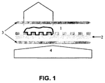
- Fig. 1 shows a schematic representation of the device according to the invention.
- the biological material 1 (object) to be examined is placed directly on the nanostructured surface 2, which is placed between two crossed polarization filters 3.
- the nanostructured surface has periodic cavities associated with a fluid, i. a gas, in particular air, or a liquid, in particular an aqueous solution are filled.
- a fluid i. a gas, in particular air, or a liquid, in particular an aqueous solution are filled.
- resonances can form depending on geometric and material parameters. These resonances are measurable with a transmission measurement, but superimposed with a disturbing portion of the light source. Placing two crossed polarizing filters before and after the photonic crystal, only the resonances are transmitted.
- the transmitted light is thus a "fingerprint" of the photonic crystal.
- parameters of the crystal e.g. the refractive index on the surface (due to presence of objects), this fingerprint also changes.
- planar photonic crystals can be z. B. produce by means of hot stamping in a very cost-effective manner.
- a stamp is pressed with the desired nanostructuring under pressure and heat to a suitable substrate material.
- a decisive advantage of the method according to the invention and the device according to the invention is the fact that the penetration depth of these resonances from the photonic crystal into the biological material can be controlled by the choice of the photonic crystal. Thus, only objects in this area are visible. All objects which are located at a greater distance from the surface of the photonic crystal are not visible with this device according to the invention and with the measuring method according to the invention and therefore do not contribute in any way to disturbing effects. It is thus possible to observe processes on the surface without disturbing influences.
- the selected viewing area can be selected depending on the object / process to be observed. This range will preferably be between 1 and 2000 nm, more preferably in the range 10 to 200 nm.
- Suitable materials for planar photonic crystals are all transparent materials, such as, for example, metal oxides, semiconductors, glass or polymers.
- materials having a lower refractive index than the photonic crystal can be used.
- the surface photonic crystals may be functionalized such that upon contact with the material to be examined, a change in the refractive index that results in resonance occurs.
- the functionalization can be, for example, a substrate or antibody capable of binding certain components of the material to be investigated.
- polarization filters all optically transparent media which pass only electromagnetic waves of a specific polarization are considered as polarization filters.
- polarizing films or higher quality polarizers in glass can be used.
- the photonic crystals can be applied directly to the microscope slide used for microscopy.
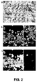
- Fig. 2 Lung carcinoma cells are shown in part on a planar photonic crystal (c), in part on an unstructured surface with different types of microscopy at 20x magnification.
- the planar photonic crystal used here consists of a niobium pentoxide layer on a quartz substrate. In this layer holes are introduced in a triangular arrangement. Under the light microscope ( Fig. 2a ), the transparency of these cells hinders to clearly recognize their outline. It is different in the phase contrast microscope, this uses various screens and a complex optics to make the transparent cells visible ( Fig. 2b ).
- Fig. 3 For example, the resonances in the photonic crystal are shown depending on the refractive index of the environment. With increasing refractive index, on the one hand, a shift of these resonances and, on the other hand, an increase in intensity can be observed. Thus, with a refractive index of 1, which corresponds to that of air, no resonances can be recognized. With a refractive index of 1.5, which is about the refractive index of cells, 5 resonances are formed, which contribute to the fact that light is transmitted at this point.
Landscapes
- Physics & Mathematics (AREA)
- Chemical & Material Sciences (AREA)
- General Physics & Mathematics (AREA)
- Optics & Photonics (AREA)
- Analytical Chemistry (AREA)
- Crystallography & Structural Chemistry (AREA)
- Microscoopes, Condenser (AREA)
- Investigating Or Analysing Materials By Optical Means (AREA)
Description
- Die Erfindung betrifft eine Vorrichtung und ein Verfahren, welche den Kontrast von Objekten in der optischen Mikroskopie erhöhen und es dabei gleichzeitig erlaubt das Verhalten an Grenzflächen zu beobachten.
- Die Erkennbarkeit von Details in einem Bild hängt von der Auflösung und dem Kontrast des Bildes ab. Insbesondere die Lichtmikroskopie von biologischen Objekten wird in vielen Fällen durch Kontrastarmut der erzeugten Bilder beeinträchtigt, nämlich immer dann, wenn die Objekte nicht durch allgemeine Lichtabsorption (Abdunklung), durch spektral spezifische Lichtabsorption (Eigenfarben) oder durch sehr starke Unterschiede im Lichtbrechungsindex mit ausreichendem Kontrast erscheinen. Deshalb gibt es verschiedene Methoden, um den Kontrast zu erhöhen. Zum Beispiel werden einzelne Objekte oder ihre Bestandteile spezifisch mit Farbstoffen angefärbt. Dabei ist es ein Vorteil, Farben zu wählen, die einen hohen Kontrast zueinander haben, dieses ist z.B. bei Komplementärfarben der Fall. Der Methode der Einfärbung sind aber insbesondere bei Untersuchung von biologischem Lebend-Material Grenzen gesetzt.
- Eine andere Methode ist, die Beleuchtungsapertur zu verringern, indem man die Irisblende des Beleuchtungsapparats (des Kondensors) verengt. Dadurch werden Objektteile mit unterschiedlichem Lichtbrechungsindex mit stärkerem Kontrast dargestellt. Dieses Verfahren hat aber den schwerwiegenden Nachteil, dass die Auflösung des Bildes stark verringert wird, denn das Auflösungsvermögen des Mikroskops ist von der numerischen Apertur der Objektbeleuchtung abhängig.
- Ein großer Fortschritt in der Kontrasterhöhung war die Erfindung des Phasenkontrastmikroskops durch Frits Zernike, welches ihm 1953 den Nobelpreis einbrachte. Mit dem Phasenkontrastmikroskop gelingt es den Hell-Dunkel-Kontrast zu vergrößern ohne dabei das Auflösungsvermögen wesentlich zu reduzieren. Beim Phasenkontrastmikroskop wird der Phasenunterschied, der sich ergibt wenn Licht durch ein Medium mit höherem Brechungsindex als die Umgebung fällt genutzt. Durch gezielte Beeinflussung der Phasenlage des Hintergrundlichtes unabhängig vom Objektlicht gelingt die Erhöhung des Kontrastes. Für die Beeinflussung des Hintergrundlichtes wird dabei ein so genannter Phasenring verwendet.
- Photonische Kristalle verfügen über eine periodische Struktur des Brechungsindex, welche durch Beugung und Interferenz die Ausbreitung von Photonen beeinflussen. In photonischen Kristallen können sich in Abhängigkeit von geometrischen und Materialparametern Resonanzen bilden. Eine besondere Kategorie stellen die planaren photonischen Kristalle dar. Diese bestehen in der Regel aus einer dünnen Schicht eines Dielektrikums, in das die Nanostrukturierung eingebracht ist und welches von Materialien mit niedrigerem Brechungsindex umgeben ist.
- Aus "Super-resolution optical microscopy based on photonic crystal materials" Phys. Rev. B72, 085442 (2005) ist bekannt, die Auflösung bei der optischen Mikroskopie, insbesondere bei Verwendung monochromatischen Lichtes, durch photonische Kristalle zu verbessern.
- Die
DE 10 2007 016 588 A1 beschreibt photonische Kristalle als Linsen zur Verbesserung der Auflösung bei Strukturen in der Größenordnung der Wellenlänge des Lichtes. - Aus der
US 2009/0040601 A1 ist ein Polarisationsmikroskop bekannt, welches über einen photonischen Kristall zur Korrektur der Wellenlänge des Lichtes verfügt. - Weiterer Stand der Technik ist bekannt aus Y. Nazirizadeh et al., Optics Express, Bd. 16, Nr. 10 (2008), S. 7153 - 7160.
- Bei der Betrachtung biologischen Materials ist es oft von großer Bedeutung nur einen bestimmten Ausschnitt aus einer Probe zu betrachten. Zum Bespiel wenn das Verhalten von Zellen an Grenzflächen beobachtet werden soll, bei der Lichtmikroskopie wirken hier die weiteren in der Probe vorhandenen Zellen als störend, es kommt zu Überlagerungen. Die Abtrennung und separate Betrachtung der Grenzfläche und ihrer Prozesse führt dabei zu Verfälschungen des Ergebnisses da z.B. die natürliche Beweglichkeit nicht mehr gegeben ist. Das Verhalten von Zellen an Grenzflächen ist z.B. dann interessant, wenn die Zellen sich z.B. bei Verlust ihrer Vitalität vom Boden eines Behälters lösen.
- Es ist Aufgabe der Erfindung eine Vorrichtung bereitzustellen, welche es ermöglicht,
- a) das Verhalten an Grenzflächen optisch zu beobachten,
- b) den Kontrast insbesondere bei der Untersuchung transparenten Materials zu erhöhen,
- c) sowie eine optimale, kontrastreiche Farbgebung zu ermöglichen, ohne auf bereits bekannte teilweise sehr teure und aufwendige Verfahren zurückzugreifen, wie z.B. Methoden der Einfärbung durch Zusatz von Farbstoffen.
- Die Aufgabe wird gelöst durch die im ersten Anspruch beschriebene Vorrichtung sowie die in den Ansprüchen beschriebenen Verfahren.
- Erfindungsgemäß wird in den optischen Strahlengang ein Element eingeführt, das aus einer nanostrukturierten Oberfläche, welche zwischen zwei gekreuzten Polarisationsfiltern angeordnet ist, besteht, dabei muss erfindungsgemäß ein direkter Kontakt der zur untersuchenden Probe mit der nanostrukturierten Oberfläche hergestellt werden.
-
Fig. 1 zeigt eine schematische Darstellung der erfindungsgemäßen Vorrichtung. Das zu untersuchende biologische Material 1 (Objekt) wird direkt auf die nanostrukturierte Oberfläche 2 gebracht, welche zwischen zwei gekreuzten Polarisationsfiltern 3 platziert ist. - Die nanostrukturierte Oberfläche verfügt über periodisch angeordnete Hohlräume, die mit einem Fluidum d.h. einem Gas, insbesondere Luft, oder einer Flüssigkeit, insbesondere einer wässrigen Lösung gefüllt sind. In planaren photonischen Kristallen können sich in Abhängigkeit von geometrischen und Materialparametern Resonanzen bilden. Diese Resonanzen sind mit einer Transmissionsmessung messbar, jedoch mit einem störenden Anteil der Lichtquelle überlagert. Platziert man zwei gekreuzte Polarisationsfilter vor und nach dem photonischen Kristall, werden nur die Resonanzen transmittiert.
- Das transmittierte Licht ist somit ein "Fingerabdruck" des photonischen Kristalls. Ändern sich nun Parameter des Kristalls, wie z.B. der Brechungsindex an der Oberfläche (durch Vorhandensein von Objekten), ändert sich auch dieser Fingerabdruck.
- Derartige planare photonische Kristalle lassen sich z. B. mittels Heißprägen auf eine sehr kostengünstige Art herstellen. Dabei wird ein Stempel mit der gewünschten Nanostrukturierung unter Druck und Hitze auf ein geeignetes Substratmaterial gepresst.
- Es hat sich nun gezeigt dass man diesen Effekt in nicht zu erwartender Art und Weise zur Erhöhung des Kontrastes in der optischen Mikroskopie verwenden kann.
- Wählt man die Luftlöcher in so einem Kristall z. B. zu groß, kommt es aufgrund des niedrigen effektiven Brechungsindexes nicht zu Resonanzbildung. Es wird bei gekreuzter Stellung der Polarisationsfilter kein Licht transmittiert. Mit einem Objekt auf der Oberfläche jedoch kann sich der effektive Brechungsindex erhöhen und es kommt Resonanzbildung. So wird nur an Stellen mit verändertem Brechungsindex der Oberfläche Licht transmittiert.
- Ein entscheidender Vorteil des erfindungsgemäßen Verfahrens und der erfindungsgemäßen Vorrichtung ist die Tatsache, dass die Eindringtiefe dieser Resonanzen aus dem photonischen Kristall in das biologische Material durch Wahl des photonischen Kristalls steuerbar ist. Es sind somit nur Objekte in diesem Bereich sichtbar. Alle Objekte, die sich in größerer Entfernung zur Oberfläche des photonischen Kristalls befinden, sind mit dieser erfindungsgemäßen Vorrichtung und mit dem erfindungsgemäßen Messverfahren nicht sichtbar und tragen daher in keiner Weise zu störenden Effekten bei. Es ist somit möglich, Vorgänge an der Oberfläche ohne störende Einflüsse zu beobachten. Der ausgewählte Sichtbereich kann dabei in Abhängigkeit von dem zu beobachtenden Objekt / Vorgang gewählt werden. Bevorzugt wird dieser Bereich zwischen 1 und 2000 nm liegen, besonders bevorzugt im Bereich 10 bis 200 nm.
- Ist die Distanz vom Objekt zur Oberfläche größer als diese Eindringtiefe, erfährt das Objekt ebenfalls keine Kontrasterhöhung.
- Als Materialien für planare photonische Kristalle kommen alle transparenten Materialien in Frage, wie zum Beispiel Metalloxide, Halbleiter, Glas oder Polymere. Als Substrat für solche Strukturen können Materialien eingesetzt werden, die einen niedrigeren Brechungsindex als der photonische Kristall aufweisen.
- In einer besonderen Ausführungsform können die photonischen Kristalle an der Oberfläche derart funktionalisiert sein, das nach Inkontakttreten mit dem zu untersuchenden Material eine Änderung des Brechungsindex, welche zur Resonanz führt, auftritt.
- Die Funktionalisierung kann z.B. ein Substrat oder Antikörper sein, der bestimmte Komponenten des zu untersuchenden Materials zu binden vermag.
- Als Polarisationsfilter kommen dabei alle optisch transparenten Medien, welche nur elektromagnetische Wellen einer bestimmten Polarisation durchlassen in Frage. Es können beispielsweise Polarisationsfolien oder höherwertigere Polarisatoren in Glas verwendet werden.
- In einer besonders vorteilhaften Ausführungsform können die photonischen Kristalle direkt auf den zur Mikroskopie verwendeten Objektträger aufgebracht sein.
- Die Erfindung wird anhand eines Ausführungsbeispiels näher erläutert. In
Fig. 2 sind Lungenkarzinomzellen zum Teil auf einem planaren photonischen Kristall (c), zum Teil auf einer nicht strukturierten Oberfläche mit unterschiedlichen Mikroskopiearten bei 20-facher Vergrößerung gezeigt. Der hier verwendete planare photonische Kristall besteht aus einer Niobpentoxid Schicht auf einem Quarz Substrat. In diese Schicht sind Löcher in einer triangularen Anordnung eingebracht. Unter dem Lichtmikroskop (Fig. 2a ) ist die Transparenz dieser Zellen hinderlich, um ihren Umriss eindeutig zu erkennen. Anders ist es bei dem Phasenkontrastmikroskop, dieses benutzt diverse Blenden und eine aufwendige Optik, um die transparenten Zellen sichtbar zu machen (Fig. 2b ). Mit gekreuzten Polarisationsfiltern und konventionelle Lichtmikroskopie erhalten wir mit der erfindungsgemäßen Vorrichtung (c) eine Kontrasterhöhung nach der oben beschriebenen Methode, jedoch ohne teuere Optik. Die hier eingesetzten Polarisationsfolien weisen einen Extinktionskoeffizient von 8.500:1 auf. Die Farbe der Zellen, ist durch die geometrischen Parameter des photonischen Kristalls gegeben, wobei fast alle Farben realisierbar sind. - Um diese Ergebnisse theoretisch zu bestätigen, wurden Transmissionssimulationen mit der Finite-Differenzen-Methode im Zeitbereich durchgeführt. In
Fig. 3 sind die Resonanzen im photonischen Kristall abhängig von dem Brechungsindex der Umgebung gezeigt. Mit steigendem Brechungsindex sind zum einen eine Verschiebung dieser Resonanzen und zum anderen eine Intensitätszunahme zu beobachten. So sind bei einem Brechungsindex von 1, welcher dem von Luft entspricht, keine Resonanzen zu erkennen. Bei einem Brechungsindex von 1,5, der etwa der Brechungsindex von Zellen ist, bilden sich 5 Resonanzen, die dazu beitragen, dass an dieser Stelle Licht transmittiert wird. -
- 1
- zu untersuchendes Material (Objekt)
- 2
- photonischer Kristall
- 3
- Polarisationsfilter
Claims (3)
- Mikroskop mit- einer Linsensoptik,- einer in die Linsenoptik Licht einstrahlenden Lichtquelle (4),- einem zwischen Lichtquelle (4) und Linsenoptik angeordneten Objekttisch zur Aufnahme eines zu mikroskopierenden Objekts,- einem zwischen der Lichtquelle (4) und dem Objekttisch angeordneten ersten Polarisationsfilter (3),- einem zwischen dem Objekttisch und der Linsenoptik angeordneten, zum ersten Polarisationsfilter um 90° gedrehten zweiten Polarisationsfilter (3), und- einem im Strahlengang angeordneten photonischen Kristall, der durch Nanostrukturierung der Oberfläche in einem Bereich eines Objektträgers oder Dechglases gebildet ist, wobei die Oberfläche des photonischen Kritalls über periodisch angeordnete Hohlräume verfügt,wobei der photonische Kristall in Kontakt mit dem Objekt gebracht ist,
woloei das Objekt ein biologisches Material ist, und wobei
die Resonanzen des photonischen Kristalls im sichtbaren Lichtspektrum liegen und erst bei Aufhringen des Objekts durch Änderung des Brechungsindex an der Oberfläche des photonischen Kristalls entstehen. - Anordnung nach Anspruch 1,
dadurch gekennzeichnet, dass
der photonische Kristall ein planarer photonischer Kristall ist. - Anordnung nach einem der vorhergehenden Ansprüche,
dadurch gekennzeichnet, dass
der Objektträger mit dem photonischen Kristall beschichtet ist.
Applications Claiming Priority (2)
| Application Number | Priority Date | Filing Date | Title |
|---|---|---|---|
| DE102010005860A DE102010005860A1 (de) | 2010-01-26 | 2010-01-26 | Vorrichtung und Verfahren zur Kontrasterhöhung in der Mikroskopie |
| PCT/DE2011/000054 WO2011091782A1 (de) | 2010-01-26 | 2011-01-20 | Objektträger mit photonischem kristall zur kontrasterhöhung in der mikroskopie |
Publications (2)
| Publication Number | Publication Date |
|---|---|
| EP2529265A1 EP2529265A1 (de) | 2012-12-05 |
| EP2529265B1 true EP2529265B1 (de) | 2016-08-24 |
Family
ID=43920665
Family Applications (1)
| Application Number | Title | Priority Date | Filing Date |
|---|---|---|---|
| EP11712155.8A Not-in-force EP2529265B1 (de) | 2010-01-26 | 2011-01-20 | Mikroskopie mit einem objektträger oder deckglas mit photonischem kristall zur kontrasterhöhung |
Country Status (3)
| Country | Link |
|---|---|
| EP (1) | EP2529265B1 (de) |
| DE (1) | DE102010005860A1 (de) |
| WO (1) | WO2011091782A1 (de) |
Families Citing this family (3)
| Publication number | Priority date | Publication date | Assignee | Title |
|---|---|---|---|---|
| DE102011118641A1 (de) | 2011-11-16 | 2013-05-16 | Christian-Albrechts-Universität Zu Kiel | Verfahren zur Bestimmung der Dicke von Objekten mit Hilfe eines Licht-Mikroskops |
| WO2017109057A1 (en) * | 2015-12-23 | 2017-06-29 | Koninklijke Philips N.V. | Fluorescence calibration slide |
| RU2672980C1 (ru) * | 2017-11-01 | 2018-11-21 | Федеральное государственное бюджетное образовательное учреждение высшего образования "Сибирский государственный университет геосистем и технологий" | Микроскопное покровное стекло |
Family Cites Families (5)
| Publication number | Priority date | Publication date | Assignee | Title |
|---|---|---|---|---|
| US20050142654A1 (en) * | 2002-10-18 | 2005-06-30 | Kazuji Matsumoto | Slide glass, cover glass and pathologic diagnosis system |
| US7072098B2 (en) * | 2003-01-29 | 2006-07-04 | Daniel Roy Solli | Method and apparatus for polarization control with photonic crystals |
| JPWO2006123712A1 (ja) | 2005-05-18 | 2008-12-25 | オリンパス株式会社 | 偏光顕微鏡 |
| DE102007016588B4 (de) | 2007-04-05 | 2014-10-09 | Fraunhofer-Gesellschaft zur Förderung der angewandten Forschung e.V. | Mikroskop mit Subwellenlängenauflösung und Verfahren zum Erzeugen eines Bilds eines Objekts |
| US7768640B2 (en) * | 2007-05-07 | 2010-08-03 | The Board Of Trustees Of The University Of Illinois | Fluorescence detection enhancement using photonic crystal extraction |
-
2010
- 2010-01-26 DE DE102010005860A patent/DE102010005860A1/de not_active Ceased
-
2011
- 2011-01-20 WO PCT/DE2011/000054 patent/WO2011091782A1/de not_active Ceased
- 2011-01-20 EP EP11712155.8A patent/EP2529265B1/de not_active Not-in-force
Also Published As
| Publication number | Publication date |
|---|---|
| DE102010005860A1 (de) | 2011-07-28 |
| WO2011091782A1 (de) | 2011-08-04 |
| EP2529265A1 (de) | 2012-12-05 |
Similar Documents
| Publication | Publication Date | Title |
|---|---|---|
| EP2158475B1 (de) | Wellenlängensensitiver optischer aufbau und dessen verwendung | |
| EP2350618B1 (de) | Fluoreszenzmikroskop mit phasenmaske | |
| DE102013112596B4 (de) | Anordnung zur Lichtblattmikroskopie | |
| EP3368935B1 (de) | Probenbegrenzungselement aus nanoporösem material für die immersionsmikroskopie | |
| DE102013112595B4 (de) | Anordnung zur Lichtblattmikroskopie | |
| EP3019904A1 (de) | Anordnung zur lichtblattmikroskopie | |
| EP4042222B1 (de) | Verfahren und vorrichtung zur aberrationskorrektur in der fluoreszenzmikroskopie | |
| WO2016096303A1 (de) | Verfahren zur lichtblattmikroskopischen untersuchung einer probe | |
| DE112015003920B4 (de) | Optisches Bilderzeugungssystem, Beleuchtungsvorrichtung, Mikroskopvorrichtung und Phasenmodulationselement | |
| EP2745158B1 (de) | Messverfahren für höhenprofile von oberflächen | |
| DE102017204325A1 (de) | Anordnung, Mikroskop und Verfahren zur TIRF-Mikroskopie | |
| EP3411680A1 (de) | Miniaturspektrometer und verfahren zum schalten eines miniaturspektrometers zwischen abbildungsmodus und spektrometermodus | |
| WO2011091782A1 (de) | Objektträger mit photonischem kristall zur kontrasterhöhung in der mikroskopie | |
| DE102015221991A1 (de) | Mikroskopierverfahren zur Ermittlung eines Kontrastbildes und Mikroskop | |
| EP3374755B1 (de) | Lichtmikroskop und verfahren zum bestimmen einer wellenlängenabhängigen brechzahl eines probenmediums | |
| DE10024135B4 (de) | Mikroskop | |
| DE102018122652B4 (de) | Spektralauflösende, hochauflösende 3D-Lokalisierungmikroskopie | |
| DE102004032953A1 (de) | Phasenfilter | |
| WO2016071033A1 (de) | Verfahren zur erzeugung eines bildes einer probe | |
| EP1892508A1 (de) | Anordnung für ein optisches System für polarisationsabhängige zeitaufgelöste optische Spektroskopie, optisches Messsystem und Verfahren zum polarisationsabhängigen spektroskopischen Untersuchen von Messlicht | |
| DE102019117671A1 (de) | Vorrichtung und Verfahren zur Untersuchung von chiralen Proben | |
| DE102005023137B4 (de) | Anordnung zur hochauflösenden digitalen Inline-Holographie | |
| EP3686645A1 (de) | Beleuchtungseinrichtung für ein abbildendes optisches gerät sowie verfahren zur detektion | |
| DE102005061984B4 (de) | Druckzelle zur optischen Beobachtung unter Druck | |
| DE102011118641A1 (de) | Verfahren zur Bestimmung der Dicke von Objekten mit Hilfe eines Licht-Mikroskops |
Legal Events
| Date | Code | Title | Description |
|---|---|---|---|
| PUAI | Public reference made under article 153(3) epc to a published international application that has entered the european phase |
Free format text: ORIGINAL CODE: 0009012 |
|
| 17P | Request for examination filed |
Effective date: 20120814 |
|
| AK | Designated contracting states |
Kind code of ref document: A1 Designated state(s): AL AT BE BG CH CY CZ DE DK EE ES FI FR GB GR HR HU IE IS IT LI LT LU LV MC MK MT NL NO PL PT RO RS SE SI SK SM TR |
|
| DAX | Request for extension of the european patent (deleted) | ||
| 17Q | First examination report despatched |
Effective date: 20140901 |
|
| 17Q | First examination report despatched |
Effective date: 20140916 |
|
| GRAP | Despatch of communication of intention to grant a patent |
Free format text: ORIGINAL CODE: EPIDOSNIGR1 |
|
| INTG | Intention to grant announced |
Effective date: 20160322 |
|
| GRAS | Grant fee paid |
Free format text: ORIGINAL CODE: EPIDOSNIGR3 |
|
| GRAA | (expected) grant |
Free format text: ORIGINAL CODE: 0009210 |
|
| AK | Designated contracting states |
Kind code of ref document: B1 Designated state(s): AL AT BE BG CH CY CZ DE DK EE ES FI FR GB GR HR HU IE IS IT LI LT LU LV MC MK MT NL NO PL PT RO RS SE SI SK SM TR |
|
| REG | Reference to a national code |
Ref country code: GB Ref legal event code: FG4D Free format text: NOT ENGLISH |
|
| REG | Reference to a national code |
Ref country code: CH Ref legal event code: EP |
|
| REG | Reference to a national code |
Ref country code: AT Ref legal event code: REF Ref document number: 823590 Country of ref document: AT Kind code of ref document: T Effective date: 20160915 |
|
| REG | Reference to a national code |
Ref country code: IE Ref legal event code: FG4D Free format text: LANGUAGE OF EP DOCUMENT: GERMAN |
|
| REG | Reference to a national code |
Ref country code: DE Ref legal event code: R096 Ref document number: 502011010504 Country of ref document: DE |
|
| REG | Reference to a national code |
Ref country code: LT Ref legal event code: MG4D |
|
| REG | Reference to a national code |
Ref country code: NL Ref legal event code: MP Effective date: 20160824 |
|
| REG | Reference to a national code |
Ref country code: FR Ref legal event code: PLFP Year of fee payment: 7 |
|
| PG25 | Lapsed in a contracting state [announced via postgrant information from national office to epo] |
Ref country code: NL Free format text: LAPSE BECAUSE OF FAILURE TO SUBMIT A TRANSLATION OF THE DESCRIPTION OR TO PAY THE FEE WITHIN THE PRESCRIBED TIME-LIMIT Effective date: 20160824 Ref country code: NO Free format text: LAPSE BECAUSE OF FAILURE TO SUBMIT A TRANSLATION OF THE DESCRIPTION OR TO PAY THE FEE WITHIN THE PRESCRIBED TIME-LIMIT Effective date: 20161124 Ref country code: FI Free format text: LAPSE BECAUSE OF FAILURE TO SUBMIT A TRANSLATION OF THE DESCRIPTION OR TO PAY THE FEE WITHIN THE PRESCRIBED TIME-LIMIT Effective date: 20160824 Ref country code: LT Free format text: LAPSE BECAUSE OF FAILURE TO SUBMIT A TRANSLATION OF THE DESCRIPTION OR TO PAY THE FEE WITHIN THE PRESCRIBED TIME-LIMIT Effective date: 20160824 Ref country code: RS Free format text: LAPSE BECAUSE OF FAILURE TO SUBMIT A TRANSLATION OF THE DESCRIPTION OR TO PAY THE FEE WITHIN THE PRESCRIBED TIME-LIMIT Effective date: 20160824 Ref country code: IT Free format text: LAPSE BECAUSE OF FAILURE TO SUBMIT A TRANSLATION OF THE DESCRIPTION OR TO PAY THE FEE WITHIN THE PRESCRIBED TIME-LIMIT Effective date: 20160824 Ref country code: HR Free format text: LAPSE BECAUSE OF FAILURE TO SUBMIT A TRANSLATION OF THE DESCRIPTION OR TO PAY THE FEE WITHIN THE PRESCRIBED TIME-LIMIT Effective date: 20160824 |
|
| PG25 | Lapsed in a contracting state [announced via postgrant information from national office to epo] |
Ref country code: PT Free format text: LAPSE BECAUSE OF FAILURE TO SUBMIT A TRANSLATION OF THE DESCRIPTION OR TO PAY THE FEE WITHIN THE PRESCRIBED TIME-LIMIT Effective date: 20161226 Ref country code: ES Free format text: LAPSE BECAUSE OF FAILURE TO SUBMIT A TRANSLATION OF THE DESCRIPTION OR TO PAY THE FEE WITHIN THE PRESCRIBED TIME-LIMIT Effective date: 20160824 Ref country code: SE Free format text: LAPSE BECAUSE OF FAILURE TO SUBMIT A TRANSLATION OF THE DESCRIPTION OR TO PAY THE FEE WITHIN THE PRESCRIBED TIME-LIMIT Effective date: 20160824 Ref country code: GR Free format text: LAPSE BECAUSE OF FAILURE TO SUBMIT A TRANSLATION OF THE DESCRIPTION OR TO PAY THE FEE WITHIN THE PRESCRIBED TIME-LIMIT Effective date: 20161125 Ref country code: LV Free format text: LAPSE BECAUSE OF FAILURE TO SUBMIT A TRANSLATION OF THE DESCRIPTION OR TO PAY THE FEE WITHIN THE PRESCRIBED TIME-LIMIT Effective date: 20160824 |
|
| PG25 | Lapsed in a contracting state [announced via postgrant information from national office to epo] |
Ref country code: EE Free format text: LAPSE BECAUSE OF FAILURE TO SUBMIT A TRANSLATION OF THE DESCRIPTION OR TO PAY THE FEE WITHIN THE PRESCRIBED TIME-LIMIT Effective date: 20160824 Ref country code: RO Free format text: LAPSE BECAUSE OF FAILURE TO SUBMIT A TRANSLATION OF THE DESCRIPTION OR TO PAY THE FEE WITHIN THE PRESCRIBED TIME-LIMIT Effective date: 20160824 |
|
| REG | Reference to a national code |
Ref country code: DE Ref legal event code: R097 Ref document number: 502011010504 Country of ref document: DE |
|
| PG25 | Lapsed in a contracting state [announced via postgrant information from national office to epo] |
Ref country code: DK Free format text: LAPSE BECAUSE OF FAILURE TO SUBMIT A TRANSLATION OF THE DESCRIPTION OR TO PAY THE FEE WITHIN THE PRESCRIBED TIME-LIMIT Effective date: 20160824 Ref country code: PL Free format text: LAPSE BECAUSE OF FAILURE TO SUBMIT A TRANSLATION OF THE DESCRIPTION OR TO PAY THE FEE WITHIN THE PRESCRIBED TIME-LIMIT Effective date: 20160824 Ref country code: SK Free format text: LAPSE BECAUSE OF FAILURE TO SUBMIT A TRANSLATION OF THE DESCRIPTION OR TO PAY THE FEE WITHIN THE PRESCRIBED TIME-LIMIT Effective date: 20160824 Ref country code: SM Free format text: LAPSE BECAUSE OF FAILURE TO SUBMIT A TRANSLATION OF THE DESCRIPTION OR TO PAY THE FEE WITHIN THE PRESCRIBED TIME-LIMIT Effective date: 20160824 Ref country code: BG Free format text: LAPSE BECAUSE OF FAILURE TO SUBMIT A TRANSLATION OF THE DESCRIPTION OR TO PAY THE FEE WITHIN THE PRESCRIBED TIME-LIMIT Effective date: 20161124 Ref country code: BE Free format text: LAPSE BECAUSE OF NON-PAYMENT OF DUE FEES Effective date: 20170131 Ref country code: CZ Free format text: LAPSE BECAUSE OF FAILURE TO SUBMIT A TRANSLATION OF THE DESCRIPTION OR TO PAY THE FEE WITHIN THE PRESCRIBED TIME-LIMIT Effective date: 20160824 |
|
| PLBE | No opposition filed within time limit |
Free format text: ORIGINAL CODE: 0009261 |
|
| STAA | Information on the status of an ep patent application or granted ep patent |
Free format text: STATUS: NO OPPOSITION FILED WITHIN TIME LIMIT |
|
| 26N | No opposition filed |
Effective date: 20170526 |
|
| PG25 | Lapsed in a contracting state [announced via postgrant information from national office to epo] |
Ref country code: SI Free format text: LAPSE BECAUSE OF FAILURE TO SUBMIT A TRANSLATION OF THE DESCRIPTION OR TO PAY THE FEE WITHIN THE PRESCRIBED TIME-LIMIT Effective date: 20160824 |
|
| REG | Reference to a national code |
Ref country code: CH Ref legal event code: PL |
|
| PG25 | Lapsed in a contracting state [announced via postgrant information from national office to epo] |
Ref country code: MC Free format text: LAPSE BECAUSE OF FAILURE TO SUBMIT A TRANSLATION OF THE DESCRIPTION OR TO PAY THE FEE WITHIN THE PRESCRIBED TIME-LIMIT Effective date: 20160824 |
|
| PG25 | Lapsed in a contracting state [announced via postgrant information from national office to epo] |
Ref country code: LI Free format text: LAPSE BECAUSE OF NON-PAYMENT OF DUE FEES Effective date: 20170131 Ref country code: CH Free format text: LAPSE BECAUSE OF NON-PAYMENT OF DUE FEES Effective date: 20170131 |
|
| REG | Reference to a national code |
Ref country code: IE Ref legal event code: MM4A |
|
| PG25 | Lapsed in a contracting state [announced via postgrant information from national office to epo] |
Ref country code: LU Free format text: LAPSE BECAUSE OF NON-PAYMENT OF DUE FEES Effective date: 20170120 |
|
| REG | Reference to a national code |
Ref country code: FR Ref legal event code: PLFP Year of fee payment: 8 |
|
| REG | Reference to a national code |
Ref country code: BE Ref legal event code: MM Effective date: 20170131 |
|
| PG25 | Lapsed in a contracting state [announced via postgrant information from national office to epo] |
Ref country code: IE Free format text: LAPSE BECAUSE OF NON-PAYMENT OF DUE FEES Effective date: 20170120 |
|
| REG | Reference to a national code |
Ref country code: AT Ref legal event code: MM01 Ref document number: 823590 Country of ref document: AT Kind code of ref document: T Effective date: 20170120 |
|
| PG25 | Lapsed in a contracting state [announced via postgrant information from national office to epo] |
Ref country code: AT Free format text: LAPSE BECAUSE OF NON-PAYMENT OF DUE FEES Effective date: 20170120 |
|
| PG25 | Lapsed in a contracting state [announced via postgrant information from national office to epo] |
Ref country code: MT Free format text: LAPSE BECAUSE OF FAILURE TO SUBMIT A TRANSLATION OF THE DESCRIPTION OR TO PAY THE FEE WITHIN THE PRESCRIBED TIME-LIMIT Effective date: 20160824 |
|
| PG25 | Lapsed in a contracting state [announced via postgrant information from national office to epo] |
Ref country code: AL Free format text: LAPSE BECAUSE OF FAILURE TO SUBMIT A TRANSLATION OF THE DESCRIPTION OR TO PAY THE FEE WITHIN THE PRESCRIBED TIME-LIMIT Effective date: 20160824 |
|
| PG25 | Lapsed in a contracting state [announced via postgrant information from national office to epo] |
Ref country code: HU Free format text: LAPSE BECAUSE OF FAILURE TO SUBMIT A TRANSLATION OF THE DESCRIPTION OR TO PAY THE FEE WITHIN THE PRESCRIBED TIME-LIMIT; INVALID AB INITIO Effective date: 20110120 |
|
| PG25 | Lapsed in a contracting state [announced via postgrant information from national office to epo] |
Ref country code: CY Free format text: LAPSE BECAUSE OF NON-PAYMENT OF DUE FEES Effective date: 20160824 |
|
| PG25 | Lapsed in a contracting state [announced via postgrant information from national office to epo] |
Ref country code: MK Free format text: LAPSE BECAUSE OF FAILURE TO SUBMIT A TRANSLATION OF THE DESCRIPTION OR TO PAY THE FEE WITHIN THE PRESCRIBED TIME-LIMIT Effective date: 20160824 |
|
| PG25 | Lapsed in a contracting state [announced via postgrant information from national office to epo] |
Ref country code: TR Free format text: LAPSE BECAUSE OF FAILURE TO SUBMIT A TRANSLATION OF THE DESCRIPTION OR TO PAY THE FEE WITHIN THE PRESCRIBED TIME-LIMIT Effective date: 20160824 |
|
| PG25 | Lapsed in a contracting state [announced via postgrant information from national office to epo] |
Ref country code: IS Free format text: LAPSE BECAUSE OF FAILURE TO SUBMIT A TRANSLATION OF THE DESCRIPTION OR TO PAY THE FEE WITHIN THE PRESCRIBED TIME-LIMIT Effective date: 20161224 |
|
| REG | Reference to a national code |
Ref country code: DE Ref legal event code: R082 Ref document number: 502011010504 Country of ref document: DE Representative=s name: HEESCHEN, SVEN, DIPL.-PHYS., DE |
|
| PGFP | Annual fee paid to national office [announced via postgrant information from national office to epo] |
Ref country code: FR Payment date: 20210120 Year of fee payment: 11 |
|
| PGFP | Annual fee paid to national office [announced via postgrant information from national office to epo] |
Ref country code: GB Payment date: 20210122 Year of fee payment: 11 Ref country code: DE Payment date: 20210120 Year of fee payment: 11 |
|
| REG | Reference to a national code |
Ref country code: DE Ref legal event code: R119 Ref document number: 502011010504 Country of ref document: DE |
|
| GBPC | Gb: european patent ceased through non-payment of renewal fee |
Effective date: 20220120 |
|
| PG25 | Lapsed in a contracting state [announced via postgrant information from national office to epo] |
Ref country code: GB Free format text: LAPSE BECAUSE OF NON-PAYMENT OF DUE FEES Effective date: 20220120 Ref country code: DE Free format text: LAPSE BECAUSE OF NON-PAYMENT OF DUE FEES Effective date: 20220802 |
|
| PG25 | Lapsed in a contracting state [announced via postgrant information from national office to epo] |
Ref country code: FR Free format text: LAPSE BECAUSE OF NON-PAYMENT OF DUE FEES Effective date: 20220131 |