EP2527236A1 - Schaltbare Getriebeanordnung - Google Patents
Schaltbare Getriebeanordnung Download PDFInfo
- Publication number
- EP2527236A1 EP2527236A1 EP11004389A EP11004389A EP2527236A1 EP 2527236 A1 EP2527236 A1 EP 2527236A1 EP 11004389 A EP11004389 A EP 11004389A EP 11004389 A EP11004389 A EP 11004389A EP 2527236 A1 EP2527236 A1 EP 2527236A1
- Authority
- EP
- European Patent Office
- Prior art keywords
- gear
- shaft
- motor
- transmission
- output shaft
- Prior art date
- Legal status (The legal status is an assumption and is not a legal conclusion. Google has not performed a legal analysis and makes no representation as to the accuracy of the status listed.)
- Granted
Links
Images


Classifications
-
- B—PERFORMING OPERATIONS; TRANSPORTING
- B62—LAND VEHICLES FOR TRAVELLING OTHERWISE THAN ON RAILS
- B62K—CYCLES; CYCLE FRAMES; CYCLE STEERING DEVICES; RIDER-OPERATED TERMINAL CONTROLS SPECIALLY ADAPTED FOR CYCLES; CYCLE AXLE SUSPENSIONS; CYCLE SIDECARS, FORECARS, OR THE LIKE
- B62K25/00—Axle suspensions
- B62K25/04—Axle suspensions for mounting axles resiliently on cycle frame or fork
- B62K25/28—Axle suspensions for mounting axles resiliently on cycle frame or fork with pivoted chain-stay
- B62K25/283—Axle suspensions for mounting axles resiliently on cycle frame or fork with pivoted chain-stay for cycles without a pedal crank, e.g. motorcycles
-
- B—PERFORMING OPERATIONS; TRANSPORTING
- B60—VEHICLES IN GENERAL
- B60K—ARRANGEMENT OR MOUNTING OF PROPULSION UNITS OR OF TRANSMISSIONS IN VEHICLES; ARRANGEMENT OR MOUNTING OF PLURAL DIVERSE PRIME-MOVERS IN VEHICLES; AUXILIARY DRIVES FOR VEHICLES; INSTRUMENTATION OR DASHBOARDS FOR VEHICLES; ARRANGEMENTS IN CONNECTION WITH COOLING, AIR INTAKE, GAS EXHAUST OR FUEL SUPPLY OF PROPULSION UNITS IN VEHICLES
- B60K17/00—Arrangement or mounting of transmissions in vehicles
- B60K17/04—Arrangement or mounting of transmissions in vehicles characterised by arrangement, location or kind of gearing
- B60K17/043—Transmission unit disposed in on near the vehicle wheel, or between the differential gear unit and the wheel
-
- B—PERFORMING OPERATIONS; TRANSPORTING
- B60—VEHICLES IN GENERAL
- B60K—ARRANGEMENT OR MOUNTING OF PROPULSION UNITS OR OF TRANSMISSIONS IN VEHICLES; ARRANGEMENT OR MOUNTING OF PLURAL DIVERSE PRIME-MOVERS IN VEHICLES; AUXILIARY DRIVES FOR VEHICLES; INSTRUMENTATION OR DASHBOARDS FOR VEHICLES; ARRANGEMENTS IN CONNECTION WITH COOLING, AIR INTAKE, GAS EXHAUST OR FUEL SUPPLY OF PROPULSION UNITS IN VEHICLES
- B60K7/00—Disposition of motor in, or adjacent to, traction wheel
- B60K7/0007—Disposition of motor in, or adjacent to, traction wheel the motor being electric
-
- B—PERFORMING OPERATIONS; TRANSPORTING
- B60—VEHICLES IN GENERAL
- B60K—ARRANGEMENT OR MOUNTING OF PROPULSION UNITS OR OF TRANSMISSIONS IN VEHICLES; ARRANGEMENT OR MOUNTING OF PLURAL DIVERSE PRIME-MOVERS IN VEHICLES; AUXILIARY DRIVES FOR VEHICLES; INSTRUMENTATION OR DASHBOARDS FOR VEHICLES; ARRANGEMENTS IN CONNECTION WITH COOLING, AIR INTAKE, GAS EXHAUST OR FUEL SUPPLY OF PROPULSION UNITS IN VEHICLES
- B60K7/00—Disposition of motor in, or adjacent to, traction wheel
- B60K2007/0038—Disposition of motor in, or adjacent to, traction wheel the motor moving together with the wheel axle
-
- B—PERFORMING OPERATIONS; TRANSPORTING
- B60—VEHICLES IN GENERAL
- B60K—ARRANGEMENT OR MOUNTING OF PROPULSION UNITS OR OF TRANSMISSIONS IN VEHICLES; ARRANGEMENT OR MOUNTING OF PLURAL DIVERSE PRIME-MOVERS IN VEHICLES; AUXILIARY DRIVES FOR VEHICLES; INSTRUMENTATION OR DASHBOARDS FOR VEHICLES; ARRANGEMENTS IN CONNECTION WITH COOLING, AIR INTAKE, GAS EXHAUST OR FUEL SUPPLY OF PROPULSION UNITS IN VEHICLES
- B60K7/00—Disposition of motor in, or adjacent to, traction wheel
- B60K2007/0061—Disposition of motor in, or adjacent to, traction wheel the motor axle being parallel to the wheel axle
-
- B—PERFORMING OPERATIONS; TRANSPORTING
- B62—LAND VEHICLES FOR TRAVELLING OTHERWISE THAN ON RAILS
- B62K—CYCLES; CYCLE FRAMES; CYCLE STEERING DEVICES; RIDER-OPERATED TERMINAL CONTROLS SPECIALLY ADAPTED FOR CYCLES; CYCLE AXLE SUSPENSIONS; CYCLE SIDECARS, FORECARS, OR THE LIKE
- B62K2202/00—Motorised scooters
-
- B—PERFORMING OPERATIONS; TRANSPORTING
- B62—LAND VEHICLES FOR TRAVELLING OTHERWISE THAN ON RAILS
- B62K—CYCLES; CYCLE FRAMES; CYCLE STEERING DEVICES; RIDER-OPERATED TERMINAL CONTROLS SPECIALLY ADAPTED FOR CYCLES; CYCLE AXLE SUSPENSIONS; CYCLE SIDECARS, FORECARS, OR THE LIKE
- B62K2204/00—Adaptations for driving cycles by electric motor
Definitions
- the invention relates to a gear arrangement according to the preamble of claim 1.
- Such gear arrangements are preferably used in areas in which a compact design with low weight is necessary or desired. Because of these properties, they are also often used to drive vehicles or mobile devices. For example, such a gear arrangement could be used as a drive for an electric scooter. It is also conceivable the use of multi-lane vehicles. For this purpose, each driven wheel could each be assigned to a gear arrangement. It would also be conceivable to use the gear arrangement for driving a plurality of wheels. In addition, such a gear arrangement but also for any other drive task can be used.
- Gear arrangements for driving electric scooters are usually housed in so-called drive train oscillations. These are usually designed such that a base body is mounted on the vehicle frame and at its opposite end a driven wheel is mounted.
- the gear arrangement with the electric motor and the transmission elements are usually positioned on or in the base body.
- the electric scooter In order to achieve a range suitable for everyday use, the electric scooter must carry a certain number of power stores with it. The currently available power storage but have a high weight. An electric scooter with sufficient range therefore usually has a high weight, which has a negative effect on the driving characteristics. However, if the user attaches importance to a scooter with low weight, the range is often unsatisfactory. The manufacturers of electric scooters are therefore constantly striving to reduce the weight of all components, including the gear assembly. On the one hand, better handling characteristics can be achieved through lower weight. On the other hand, the weight saved elsewhere offers the opportunity to carry additional power storage and to improve the range.
- the object is achieved by means of a gear arrangement with the features of the independent claim 1.
- the generic gear arrangement has for this purpose on the motor shaft at least a second, with the motor shaft rotatably connectable Motorantriebsrad, and on the transmission shaft at least a second gear, wherein the second Motorantriebsrad and the second gear are connected by means of a flexible propellant, wherein the transmission shaft further comprises a Coupling arrangement, by means of which at least optionally a torque flow from the first motor drive to the output shaft or from the second motor drive to the output shaft is adjustable.
- the motor shaft has at least two motor drive wheels, each of which is assigned a gear wheel on the gear shaft, wherein the respective Motorantriebsrad is connected by means of a flexible propellant, in particular a belt or a chain with the respective gear.
- a torque transmission device such as a chain, a belt or a cardan shaft
- a clutch arrangement is provided on the transmission shaft, which can respectively switch the torque of the first gear or the second gear on the transmission shaft, whereby the output gear is driven.
- the clutch assembly is selectively switchable to engage one of the gears and to decouple another, or the other gears.
- the base body serves as a carrier element to carry the remaining elements of the drive set rocker.
- a drive assembly to be used in vehicles for the disabled.
- a first sprocket with two tooth contours is positioned on a drive shaft.
- a second and a third sprocket are arranged, which rotate freely on the shaft.
- a displaceable coupling construction is arranged, by means of which in each case one of the sprockets can be engaged in order to connect it rotationally fixed to the output shaft.
- the second and third sprocket are each connected to the first sprocket by means of a chain. Accordingly, run between the drive shaft and the output shaft two chains.
- the gear assembly does not meet the requirements of today's vehicle concepts.
- the transmission arrangement offers no possibility for integration of a freewheel.
- the German patent application calls DE 197 51 371 A1 expressly that the integration of a transmission in the propulsion rocker is not desired, so a combination of these documents would not be considered.
- the technical progress of recent decades has led to ever smaller drive arrangements, which is why the gear arrangement of FR 542 537 due to its necessary installation space, it would no longer be considered for use in mobile applications today. Approaches to weight or space reduction are in the FR 542 537 not visible.
- the motor shaft has a first and a second end region, both of which extend from the electric motor, wherein at least the first motor drive wheel is arranged at the first end region and at least the second motor drive wheel at the second end region.
- the two end portions of the motor shaft extend from two sides of the motor housing. At least one of the motor drive wheels is positioned on each end portion.
- the at least two motor drive wheels are permanently connected non-rotatably at least in the drive direction of the electric motor. So the electric motor rotates in the corresponding direction of rotation to the electric vehicle in the usual direction of movement, i. To propel forward so transmits at least the respectively coupled by means of the clutch assembly Motorantriebsrad the torque on the transmission shaft.
- first output gear between the first gear and the second gear is arranged. Both the first output gear and the first and second gears are disposed on the transmission shaft. The driven wheel sits between the at least two gear wheels. This ensures that the transmission of the torque to the second output gear can be made in alignment with the first output gear. Accordingly, this arrangement ensures optimal use of the available, very limited space.
- a base body is provided on or in which the electric motor, the transmission shaft and the output shaft are positioned.
- the use of the base body as a support element simplifies both the pre-assembly of the gear assembly and the subsequent assembly of the drive train as a unit on the electric scooter.
- the base body may be formed as a rocker housing, which comprises at least the transmission shaft and the output shaft at least partially.
- a rocker housing in which at least some elements of the gear arrangement are received or included, these respective elements may be protected from dirt. The life of the propellant and wheels is thereby extended.
- the rocker housing receives all other elements of the gear assembly, or that they are positioned on her so that the drive train is substantially isolated from environmental influences.
- first motor drive wheel and the first gear has a first over or under reduction and the second motor drive and second gear has a second, from the first deviating over or reduction.
- the motor shaft, the transmission shaft and the output shaft are aligned parallel to each other. This leads to a simple construction of the gear arrangement.
- the motor shaft, the transmission shaft and the output shaft are arranged such that they are provided or arranged transversely to a vehicle longitudinal axis (20) when the transmission arrangement is used in a vehicle. This makes expensive arrangements, e.g. Angled drives, unnecessary for the transmission of torque.
- a freewheel is provided which decouples the output shaft in the overrun mode from the electric motor.
- coasting ie when the speed set on the electric motor is lower than the speed at the drive wheel, the freewheel ensures that the electric motor is not forced to drive. Otherwise, the motor shaft would be accelerated by the gear arrangement in sliding operation, whereby the motor would generate a voltage in the manner of a generator. On the one hand, this would influence or possibly destroy the control electronics.
- the freewheel therefore ensures a decoupling, ie mechanical separation of at least the motor shaft of the gear assembly.
- the freewheel is an element of the clutch assembly. It offers itself to combine these functions, since the clutch assembly must be designed anyway at least two switch positions. The freewheel would only be a third switch position which can be easily realized.
- At least one of the flexible propellant is a chain or a belt.
- Chains and belts have proven themselves in power and torque transmission. They are low-maintenance or maintenance-free and inexpensive to manufacture. They therefore offer themselves for use in the transmission arrangement according to the invention.
- This flexible propellant may be a chain or a belt, such as a belt. to be a toothed belt.
- Such propellants are inexpensive to purchase, straightforward in installation and maintenance, and have been proven for transmission tasks.
- Fig. 1 shows an electric motor scooter 22, the drive wheel 2 is arranged on a drive train rocker 1.
- the essential elements of the electric scooter are known from scooters, which are driven by internal combustion engines.
- the electric scooter has a steerable front wheel 23, which is arranged on a suspension fork 24.
- the front wheel is steered by means of a handlebar 25.
- the scooter has a frame which in Fig. 1 is not explicitly shown.
- the frame can usually be made of steel profiles or in any other known manner.
- the frame has a receptacle for the drive train rocker 1.
- the drive train rocker 1 is mounted pivotably about an axis 26, for example, to absorb road bumps while driving.
- a spring / damper unit 27 or another spring / damper element between the frame and drive train rocker is arranged.
- the drive set rocker 1 has for this purpose a base body 13, on which the spring / damper unit 27 can be fastened.
- Fig. 2 shows the schematic structure of a first embodiment of the transmission assembly.
- the gear arrangement is mounted on or in a base body 13 of the drive set rocker 1.
- the elements of the drive train rocker are arranged on or in the base body.
- the base body 13 is formed as a rocker housing. That is, at least some elements of the drive train rocker are at least partially encompassed by the rocker housing. In particular, this ensures protection of the elements of the drive train swingarm from external influences.
- the base body is divided into at least two areas.
- a drive region 29 and the transmission region 30 In or on the drive region 29, the motor 3 and the transmission shaft 6 and all other elements associated therewith are arranged.
- the transmission area 30 connects to the drive portion 29 and extends in the direction of the drive wheel.
- the propellant 12, and the output shaft 10 and the second output gear 11 is arranged.
- the electric motor 3, which is used to drive the drive wheel 2, is arranged in the drive region 29.
- the electric motor 3 has a motor shaft 4.
- the motor shaft 4 extends with two end portions 21 a, 21 b to two sides 19 a, 19 b from the motor housing 18.
- a first motor drive 5 is positioned at first end portion 21 a of the motor shaft 4.
- a second motor drive wheel 14 is positioned at the second end portion 21 b of the motor shaft 4.
- a transmission shaft 6 Parallel to the motor shaft 4, a transmission shaft 6 is arranged.
- the transmission shaft 6 has a first gear 7 and a second gear 15.
- the first gear 7 is aligned with the first Motorantriebsrad 5.
- the second gear 15 is aligned with the second Motorantriebsrad 14. Due to the arrangement selected, it follows that the motor shaft 4 serves as a so-called transmission input shaft.
- the first motor drive 5 is connected to the first gear 7 in the illustrated embodiment with a chain.
- the second motor drive 14 is connected to the second gear 15 with a chain.
- the motor drive wheels and gears may therefore also be referred to as engine sprockets and transmission sprockets.
- the first motor drive wheel, together with the first gear forms a first gear ratio, i. Gear.
- the second Motorantriebsrad together with the second gear a second translation and thus a second gear, which differs from the first
- a first output gear 8 is further arranged on the transmission shaft 6, .
- the first output gear 8 is positioned transversely to the vehicle longitudinal axis at the height of the engine, whereas the two motor drive wheels are positioned laterally of the motor.
- the first output gear 8 is part of the torque transmission device, by means of which the torque is transmitted from the transmission shaft to the output shaft.
- the torque transmission device in the illustrated embodiment a chain 12 and a second output gear 11.
- the first Output gear 8 is permanently, ie permanently, rotatably connected to the transmission shaft to transmit the torque from the transmission shaft.
- a clutch arrangement 17 is arranged on the transmission shaft 6. This is in the embodiment of FIG. 2 formed from two coupling elements, each of which can selectively produce a rotationally fixed connection between the gear shaft and the first gear 7 or the gear shaft and the second gear 15.
- the drive train rocker 1 has an output shaft 10, on which a second output gear 11 is arranged.
- the second driven gear 11 is aligned with the first driven gear 8 and is connected thereto by means of a chain in the illustrated embodiment.
- any other mode of transmission i. another torque transmission device may be provided.
- the two output gears could be designed as gears and transmitted by means of a gear cascade torque between the transmission shaft and output shaft.
- the use of a cardan shaft is conceivable.
- the output shaft 10 is guided by the swing housing to the outside to allow the mounting of a drive wheel 2.
- the torque transmission device is preferably permanently, i. permanently connected in rotation with the gear shaft.
- the drive region 29 has means or devices by means of which the drive train rocker can be fastened to the vehicle frame.
- the attachment means are preferably positioned in a region of the drive region which is close to the frame-side end of the drive region.
- the fastening means can also be positioned, for example, in such a way that the axis of rotation of the drive set rocker during compression is coaxial with the motor shaft. It can also be provided that the axis of rotation of the drive train rocker lies between the motor shaft and the output shaft.
- the drive region 29 has a greater width B A , ie extension transverse to the vehicle longitudinal axis 20, than the transmission region 30.
- the width of the drive region 29 is preferably twice to five times the width B ü of the transmission region.
- the widths of the drive and transmission region are selected such that the drive wheel is arranged substantially centrally of the engine.
- the drive region 29 has a length L A and the transmission region 30 has a length L Ü , wherein the length is the extent in the direction of the vehicle longitudinal axis 20.
- the length L Ü of the transmission range is usually predetermined by the diameter of the drive wheel used.
- the length of the transmission area must be sufficient so that the drive wheel maintains a minimum distance to the drive area.
- the length of the drive range is preferably as short as possible. This is achieved by means of the selected gear arrangement.
- the length of the transmission range is twice to five times the length of the drive range.
- the transmission shaft (6) and the output shaft (10) are arranged at a distance A1 to each other.
- the motor shaft (4) and the gear shaft (6) are arranged at a distance A2 to each other.
- the ratio A1 / A2 is preferably greater than 2, and particularly preferably A1 / A2> 4.
- the schematic representation does not show, for example, the braking device on the output shaft 10 in order to be able to decelerate the vehicle, as well as the necessary ventilation openings in the rocker housing and, for example, also the necessary cable bushings for the electric motor.
- the fasteners or devices on the base body 13 and swing housing are not visible, by means of which the drive train rocker is mounted on the vehicle frame.
- the motor shaft 4 is coaxial with the axis 26 about which the drive train rocker is pivotable. This ensures that when accelerating and decelerating the motor no disturbing drive influences act on the electric scooter.
- the swing housing is designed at least in two parts, wherein a dividing plane extends along the vehicle longitudinal axis 20 or at least oriented to this or, for example. runs obliquely to this.
- the swingarm housing can be divided horizontally as well as vertically. It is also conceivable, however, to provide openings in the gear housing, by which the assembly and maintenance of the individual elements is made possible.
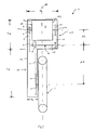
- Fig. 3 shows a schematic sectional side view of the drive train rocker 1.
- the transmission shaft 6 Adjacent to the electric motor 3, the transmission shaft 6 extends with the first gear 7, on which the propellant 9 runs.
- the first output pinion 8 On which a chain 12 is arranged.
- the first output gear 8 is in the embodiment shown in the view of Fig. 3 arranged behind the first gear 7, which is difficult to recognize due to the schematic representation.
- the chain 12 transmits the torque of the transmission shaft to the second output gear 11 and the output shaft 10, which in turn the drive wheel 2 is driven.
- gear shaft 6 and output shaft 10 along a line 28 are arranged. This has proven to be advantageous.
- FIG. 4 is also the arrangement of the gear shaft relative to the engine and to recognize the motor shaft.
- the distance between the engine and transmission shaft is selected such that the gear wheel 7 covers the engine or the motor housing, at least in some areas. That is, the sum of the added radii of the motor housing and one of the gears are greater than the distance between the motor shaft and gear shaft. If the motor housing is not round, the calculation of the sum uses the extent of the motor housing on an imaginary connecting line between the motor shaft and the gear shaft. Such a design leads to a very compact drive train swingarm. For better illustration, however, it was omitted in all figures to show the actually possible, very compact design.
- FIGS. 4 and 5 further embodiments of the gear arrangement explained in more detail.
- the same reference numerals are used for the same and the same effect components and referred to the previous description accordingly.
- the embodiment of the transmission arrangement in Fig. 4 differs from the previous embodiment by the arrangement of the motor drive wheels and the gears.
- the motor shaft 4 of the electric motor 3 extends only to one side of the motor housing.
- the motor drive wheels are arranged to the side of the engine, on which also the transmission region 30 of the drive train rocker is arranged.
- the motor drive wheels and the transmission range are thus next to the vehicle longitudinal axis 20 on the same side. If the gear arrangement is not used in a single-track vehicle, and the vehicle longitudinal axis 20 can not serve as a reference line, the motor transverse axis can be used as a reference line.
- the motor transverse axis runs transversely to the motor shaft 4 and divides the motor housing into two equal halves.
- a first Motorantriebsrad 5 and a second Motorantriebsrad 14 are arranged on the motor shaft 4, a first Motorantriebsrad 5 and a second Motorantriebsrad 14 are arranged.
- Parallel to the motor shaft 4 extends a gear shaft 6, on which two gear wheels 7, 15 and a first driven gear 8 are arranged.
- the first gear 7 is associated with the first motor drive 5 and connected thereto via a chain.
- the second gear 15 is associated with the second Motorantriebsrad 14 and also connected to a chain with this.
- the transmission shaft of this embodiment also has a clutch arrangement 17.
- the first output gear 8 is coupled to a second output gear 11, which drives an output shaft 10, which in turn drives the drive gear 2.
- the first output gear 8 is disposed between the first gear 7 and the second gear 15.
- the two motor drive wheels 5, 14 are also arranged only to one side of the motor housing.
- the motor drive wheels are not disposed to the side of the motor on which the transmission section 30 of the power take-off rocker is located.
- the motor drive wheels and the transmission area are arranged on different sides of the vehicle longitudinal axis.
- the motor drive edges transmit the torque to the gears, which are all arranged on one side of the vehicle longitudinal axis.
- the first driven gear 8 is not positioned between the gears 15, 17 in this embodiment.
- the clutch assembly of the embodiment of the FIG. 5 is formed by two Kupplungselemeten.
- the first coupling element is between the second gear 15 and the first gear 7 and can decouple the first gear 7 of the transmission shaft and solve a rotationally fixed connection to the transmission shaft and produce.
- the second coupling element is arranged on the second gear 15.
- the transmission shaft could for example pass through the second gear 15 through, wherein the second coupling element serves to connect the second gear 15 with the transmission shaft.
- the vehicle carries a number of batteries by means of which the electric motor is operated. Furthermore, an electronic control system is provided, by means of which the speed of the electric motor is controlled or controlled.
- the control electronics can be arranged in the drive train rocker or on the vehicle. When using the vehicle, e.g. selected by means of a throttle grip the desired speed, whereupon the control electronics adjusts the required speed of the electric motor.
- the drive set rocker has for connection to the electrical system of the vehicle connections or openings on the rocker housing through which the electrical connection can be made.
- the electric motor drives the at least two motor drive wheels 5, 14 by means of the motor shaft 4.
- the motor drive wheels 5, 14 are arranged on the motor shaft and rotatably connected thereto at least in the drive direction of the motor.
- the gears 7 and 15 are driven while the electric motor is running. If the motor shaft rotates in the drive direction, it drives both the first gear wheel and the second gear wheel 15 permanently.
- the torque transmitted to the two gear wheels in this way can be transmitted to the drive wheel by means of the first output gear, the respective gear or the respectively transmitting gear being selected by means of the clutch arrangement 17.
- the clutch assembly may be constructed in a conventional manner.
- an electronically controlled clutch is preferred.
- the operator of the vehicle for example, select the desired gear.
- the control electronics dictates the gear change and executes completely automatically.
- the clutch assembly 17 is therefore designed to automatically control the gear shift, i. without the intervention of a user.
- an electric actuator or other electro-hydraulic, electropneumatic or other known actuators could be used.
- the coupling is preferably bistable, i. It remains in its coupling state, even if no electricity, hydraulic pressure or similar. is applied.
- the clutch assembly may comprise a toothed or multi-plate clutch. It is also conceivable to use a so-called dog clutch. Regardless of the selected clutch or circuit arrangement, the switchability can be done by an electronic vote of the respective engine speed and torque. Likewise, a centrifugal force or centrifugal clutch can be used.
- the coupling arrangement with two coupling elements, wherein the first coupling element is positioned between the first gear 7 and the first driven gear 8, and the second coupling element between the second gear 15 and the first driven gear 8 is positioned.
- the swing housing 13 is configured to ensure lubrication of the moving chains.
- the rocker housing is designed to receive a predetermined amount of lubricating fluid, eg oil, and apply it to the chains.
- a predetermined amount of lubricating fluid eg oil
- the rocker housing is designed to receive a predetermined amount of lubricating fluid, eg oil, and apply it to the chains.
- a maintenance opening or drain and refill opening may be provided in the swing housing for maintenance.
- adjustment devices can be provided for adjusting the correct tension of the chain used, by means of which, for example, the position of the electric motor, the transmission shaft or a tensioning rail can be varied.
- the adjustment of the tension of the chain or chains is done automatically.
- the gear assembly may include one or more freewheels.
- the at least one freewheel is in overrun, i. if the speed of the drive wheel is greater than the speed of the motor shaft, the drive wheel decoupled from the electric motor.
- the first and / or second output gear may be provided with a freewheel.
- the clutch arrangement, both gears or both motor drive wheels may have a freewheel.
- the freewheel is provided as an element of the clutch assembly.
- any ratio can be selected for the engine and gear wheels, which appears reasonable for the available torque and the desired final speed.
- it is also possible to perform the translations in mirror image, ie, 1 / i 1 i 2 .
- i 1 denotes the gear ratio resulting from the first motor drive gear and the first gear wheel
- i 2 the gear ratio resulting from the second motor drive gear and the second gear wheel.
- the transmission shaft would also be arranged transversely to the output shaft in this case. It would thus be possible to direct the torque of the output shaft by means of a propeller shaft to the output shaft, wherein only at the output shaft, a deflection is necessary.
- the deflection is preferably effected by means of a bevel gear on the propeller shaft and a ring gear on the output shaft. In this case, the bevel gear would be the first driven gear and the ring gear the second driven gear.
- the transmission shaft could be arranged to provide a substantially coaxial alignment with the propeller shaft. A further simplification of the transmission results when the propeller shaft is not designed as a separate element, but the transmission shaft is extended to the area of the output shaft and takes over the function of the propeller shaft.
- the drive set rocker is in particular designed such that it extends only to one side of the wheel and the wheel leads only on one side. In other words, it extends from the swing fulcrum, i. the attachment axis 26, along the wheel, i. to one side of the longitudinal axis, only the drive train rocker, and no further supporting element.
Landscapes
- Engineering & Computer Science (AREA)
- Mechanical Engineering (AREA)
- Chemical & Material Sciences (AREA)
- Combustion & Propulsion (AREA)
- Transportation (AREA)
- Arrangement Of Transmissions (AREA)
Abstract
Description
- Die Erfindung betrifft eine Getriebeanordnung nach dem Oberbegriff des Anspruchs 1.
- Derartige Getriebeanordnungen werden bevorzugt in Bereichen eingesetzt, in denen eine kompakte Bauform mit niedrigem Gewicht notwendig bzw. angestrebt ist. Auf Grund dieser Eigenschaften werden sie auch häufig zum Antrieb von Fahrzeugen bzw. mobilen Geräten eingesetzt. Beispielsweise könnte eine solche Getriebeanordnung als Antrieb für einen Elektromotorroller genutzt werden. Denkbar ist aber auch die Nutzung bei mehrspurigen Fahrzeugen. Hierzu könnte jedes angetriebene Rad jeweils einer Getriebeanordnung zugeordnet sein. Auch wäre denkbar, die Getriebeanordnung zum Antrieb mehrerer Räder zu nutzen. Darüber hinaus ist eine solche Getriebeanordnung aber auch für jede andere Antriebsaufgabe einsetzbar.
- Getriebeanordnungen zum Antrieb von Elektromotorrollern sind in der Regel in sogenannten Triebsatzschwingen untergebracht. Diese sind üblicherweise derart gestaltet, dass ein Basiskörper am Fahrzeugrahmen montierbar ist und an dessen gegenüberliegendem Ende ein angetriebenes Rad angebracht ist. Die für die Funktion der Triebsatzschwinge notwendigen Elemente, d.h. insbesondere die Getriebeanordnung mit dem Elektromotor sowie den Getriebeelementen sind üblicherweise am oder im Basiskörper positioniert.
- Aus der gattungsgemäßen deutschen Patentanmeldung
DE 197 51 371 A1 ist ein Elektromotorroller mit einer Getriebeanordnung bekannt. Der Elektromotorroller trägt Stromspeicher, wie z.B. Batterien oder Akkumulatoren, mittels deren der in der Triebsatzschwinge angeordnete Elektromotor angetrieben wird. Um das Antriebsrad anzutreiben, wirkt der Elektromotor auf einen ersten Zugmitteltrieb, an den sich ein zweiter Zugmitteltrieb anschließt der auf die Abtriebswelle wirkt. Zwischen erstem und zweitem Zugmitteltrieb ist ein Freilauf positioniert. Mittels des Freilaufs kann der Elektromotor im Schiebebetrieb vom Antriebsrad entkoppelt werden. Der Elektromotor sowie erster und zweiter Zugmitteltrieb sind in bzw. an einem Schwingengehäuse angeordnet. Ziel dieser deutschen Patentanmeldung war es, die Nachteile, wie sie von Motorrollern mit Verbrennungsmotoren bekannt waren, zu verringern. Unter Anderem war es ein Ziel, die Nutzung eines stufenlosen oder schaltbaren Getriebes zu vermeiden, um das Gewicht des Elektrorollers zu verringern. - Um eine alltagstaugliche Reichweite zu erreichen, muss der Elektromotorroller eine gewisse Anzahl an Stromspeichern mit sich führen. Die derzeit verfügbaren Stromspeicher haben aber ein hohes Gewicht. Ein Elektroroller mit ausreichender Reichweite hat deshalb in der Regel ein hohes Gewicht, was sich negativ auf die Fahreigenschaften auswirkt. Legt der Nutzer jedoch Wert auf einen Roller mit niedrigem Gewicht, so ist die Reichweite häufig unbefriedigend. Die Hersteller von Elektromotorrollern sind deshalb ständig bestrebt, das Gewicht aller Komponenten, also auch der Getriebeanordnung zu verringern. Einerseits können durch niedrigeres Gewicht bessere Fahreigenschaften erreicht werden. Andererseits bietet das an anderer Stelle eingesparte Gewicht die Möglichkeit, zusätzliche Stromspeicher mitzuführen und die Reichweite zu verbessern.
- Es ist deshalb Aufgabe der Erfindung, eine Getriebeanordnung der eingangs genannten Art bereitzustellen, das eine möglichst geringe Baugröße und ein möglichst geringes Gewicht aufweisen soll.
- Die Aufgabe ist mittels einer Getriebeanordnung mit den Merkmalen des unabhängigen Anspruchs 1 gelöst. Die gattungsgemäße Getriebeanordnung weist hierzu an der Motorwelle mindestens ein zweites, mit der Motorwelle drehfest verbindbares Motorantriebsrad auf, sowie an der Getriebewelle mindestens ein zweites Getrieberad auf, wobei das zweite Motorantriebsrad und das zweite Getrieberad mittels eines flexiblen Treibmittels verbunden sind, wobei die Getriebewelle ferner eine Kupplungsanordnung aufweist, mittels welcher zumindest wahlweise ein Drehmomentfluss vom ersten Motorantriebsrad zur Abtriebswelle oder vom zweiten Motorantriebsrad zur Abtriebswelle einstellbar ist.
- Mit einer solchen Triebsatzschwinge wird die Möglichkeit geschaffen, einen kleineren Elektromotor zu nutzen als in den bisher bekannten Triebsatzschwingen. Die bisher in Triebsatzschwingen genutzten Elektromotoren waren dazu ausgelegt, in jeder Betriebssituation das notwendige Drehmoment bereitzustellen, das mittels einer festen, unvariablen Übersetzung an das Hinterrad übertragen wurde. Mittels des nun vorgeschlagenen Aufbaus der Triebsatzschwinge kann ein kleinerer, ggf. schwächerer Motor genutzt werden, dessen Drehmoment mittels einer Getriebeanordnung übertragen wird. Trotz der nun notwendigen Getriebeanordnung ergibt sich dennoch eine Gewichtsersparnis im Vergleich zu den bisher bekannten Triebsatzschwingen.
- Entsprechend der erfindungsgemäßen Lösung, weist die Motorwelle also mindestens zwei Motorantriebsräder auf, welchen auf der Getriebewelle jeweils ein Getrieberad zugeordnet ist, wobei das jeweilige Motorantriebsrad mittels eines flexiblen Treibmittels, insbesondere eines Riemens oder einer Kette mit dem jeweiligen Getrieberad verbunden ist. Hierdurch ergeben sich von der Motorwelle zur Getriebewelle mindestens zwei Übertragungswege. Das derart auf die Getriebewelle übertragene Drehmoment wird mittels einer Drehmomentübertragungseinrichtung, wie beispielsweise einer Kette, einem Riemen oder auch einer Kardanwelle, auf die Abtriebswelle übertragen. Hierzu ist an der Getriebewelle eine Kupplungsanordnung vorgesehen, die jeweils das Drehmoment des ersten Getrieberades oder des zweiten Getrieberades auf die Getriebewelle schalten kann, womit das Abtriebsrad angetrieben ist. Entsprechend ist die Kupplungsanordnung wahlweise umschaltbar, um eines der Getrieberäder einzukuppeln und das eine andere, bzw. die anderen Getrieberäder auszukoppeln. Der Basiskörper dient als Trägerelement, um die verbleibenden Elemente der Triebsatzschwinge zu tragen.
- Zwar ist aus dem französischen Patent
FR 542 537 DE 197 51 371 A1 ausdrücklich, dass die Integration eines Getriebes in die Triebsatzschwinge nicht gewünscht ist, weshalb eine Kombination dieser Druckschriften nicht in Betracht gezogen werden würde. Darüber hinaus hat der technische Fortschritt der letzten Jahrzehnte auch zu immer kleineren Antriebsanordnungen geführt, weshalb die Getriebeanordnung derFR 542 537 FR 542 537 - Gemäß einer Alternative der Erfindung kann vorgesehen sein, dass die Motorwelle einen ersten und einen zweiten Endbereich aufweist, die sich beide aus dem Elektromotor erstrecken, wobei am ersten Endbereich mindestens das erste Motorantriebsrad und am zweiten Endbereich mindestens das zweite Motorantriebsrad angeordnet ist. Die beiden Endbereiche der Motorwelle erstrecken sich aus zwei Seiten des Motorgehäuses. Auf jedem der Endbereiche ist mindestens eines der Motorantriebsräder positioniert. Eine solche Gestaltung erleichtert die Lagerung der Motorwelle im Motorgehäuse, da die Lasten zu beiden Seiten der Motorwelle eingeleitet werden und sich dadurch eine gleichmäßige Kraftverteilung ergibt. Zudem bietet diese Anordnung die Möglichkeit, bei einem einspurigen Fahrzeug den Elektromotor auf der Fahrzeuglängsachse, d.h. auf einer gedachten Linie zwischen Vorder- und Hinterrad zu positionieren. Hinsichtlich des Fahrverhaltens ist dies zu bevorzugen.
- Weiter kann vorgesehen sein, dass die mindestens zwei Motorantriebsräder zumindest in Antriebsrichtung des Elektromotors dauerhaft drehfest verbunden sind. Dreht sich also der Elektromotor in die entsprechende Drehrichtung, um das Elektrofahrzeug in die übliche Bewegungsrichtung, d.h. vorwärts anzutreiben, so übertragt zumindest das jeweils mittels der Kupplungsanordnung eingekuppelte Motorantriebsrad das Drehmoment auf die Getriebewelle.
- Ferner kann vorgesehen sein, dass das erste Abtriebsrad zwischen dem ersten Getrieberad und dem zweiten Getrieberad angeordnet ist. Sowohl das erste Abtriebsrad als auch die ersten und zweiten Getrieberäder sind an der Getriebewelle angeordnet. Dabei sitzt das Abtriebsrad zwischen den mindestens zwei Getrieberädern. Dies sorgt dafür, dass die Übertragung des Drehmoments auf das zweite Abtriebsrad fluchtend zum ersten Abtriebsrad erfolgen kann. Entsprechend sorgt diese Anordnung für eine optimale Nutzung des zur Verfügung stehenden, sehr begrenzten Bauraums.
- Als weitere Alternative kann vorgesehen sein, dass ein Basiskörper vorgesehen ist, an oder in dem der Elektromotor, die Getriebewelle und die Abtriebswelle positioniert sind. Die Nutzung des Basiskörpers als Trägerelement vereinfacht sowohl die Vormontage der Getriebeanordnung als auch die spätere Montage der Triebsatzschwinge als Baueinheit am Elektromotorroller.
- Ferner kann der Basiskörper als Schwingengehäuse ausgebildet sein, das zumindest die Getriebewelle und die Abtriebswelle zumindest bereichsweise umfasst. Mittels eines Schwingengehäuses, in dem zumindest manche Elemente der Getriebeanordnung aufgenommen bzw. umfasst sind, können diese jeweiligen Elemente vor Schmutz geschützt sein. Die Lebensdauer der Treibmittel und Räder wird dadurch verlängert. Hierbei kann auch vorgesehen sein, dass das Schwingengehäuse alle sonstigen Elemente der Getriebeanordnung aufnimmt, bzw. dass diese an ihr derart positioniert sind, dass der Antriebsstrang im Wesentlichen von Umwelteinflüssen isoliert ist.
- Eine weitere Gestaltungsmöglichkeit ist, dass das erste Motorantriebsrad und das erste Getrieberad eine erste Über- oder Untersetzung aufweist und das zweite Motorantriebsrad und zweite Getrieberad eine zweite, von der ersten abweichende Über- oder Untersetzung aufweist. Es werden damit zwei Über/Untersetzungen der Motordrehzahl bzw. des Motordrehmoments erzeugt. Das gewünschte Drehmoment kann dann mittels der Kupplungsanordnung auf der Getriebewelle der Abtriebswelle zugeführt werden.
- Ferner kann vorgesehen sein, dass die Motorwelle, die Getriebewelle sowie die Abtriebswelle parallel zueinander ausgerichtet sind. Dies führt zu einem einfachen Aufbau der Getriebeanordnung.
- Auch kann vorgesehen sein, dass die Motorwelle, die Getriebewelle und die Abtriebswelle derart angeordnet sind, dass sie bei einem Einsatz der Getriebeanordnung in einem Fahrzeug quer zu einer Fahrzeuglängsachse (20) vorgesehen, bzw. angeordnet, sind. Dies macht aufwendige Anordnungen, z.B. Winkeltriebe, zur Übertragung des Drehmoments überflüssig.
- Eine weitere alternative Gestaltungsmöglichkeit ist, dass ein Freilauf vorgesehen ist, welcher die Abtriebswelle im Schiebebetrieb vom Elektromotor entkoppelt. Im Schiebebetrieb, d.h. wenn die am Elektromotor eingestellte Drehzahl geringer ist als die Drehzahl am Antriebsrad, sorgt der Freilauf dafür, dass der Elektromotor nicht zwangsweise angetrieben wird. Ansonsten würde die Motorwelle im Schiebebetrieb durch die Getriebeanordnung beschleunigt, wodurch der Motor nach Art eines Generators eine Spannung erzeugen würde. Dies würde einerseits die Steuerelektronik beeinflussen oder möglicherweise zerstören. Andererseits hat sich gezeigt, dass eine kurzzeitige Einspeisung von Energie in die Batterien bzw. Akkus des Elektrofahrzeugs nicht lohnt oder für die Lebensdauer der Batterien oder Akkus sogar schädlich sein kann. Der Freilauf sorgt deshalb für eine Entkoppelung, d.h. mechanische Trennung zumindest der Motorwelle von der Getriebeanordnung.
- Ferner kann vorgesehen sein, dass der Freilauf ein Element der Kupplungsanordnung ist. Es bietet sich an diese Funktionen zu kombinieren, da die Kupplungsanordnung ohnehin gestaltet sein muss mindestens zwei Schaltstellungen zu schalten. Der Freilauf wäre lediglich eine dritte Schaltstellung die einfach realisiert werden kann.
- Als Gestaltungsvariante bietet sich an, das mindestens eines der flexiblen Treibmittel eine Kette oder ein Riemen ist. Ketten und Riemen haben sich in der Kraft- und Drehmomentübertragung bewährt. Sie sind wartungsarm bzw. wartungsfrei und günstig in der Herstellung. Sie bieten sich deshalb für eine Nutzung in der erfindungsgemäßen Getriebeanordnung an.
- Weiter ist möglich, das erste und zweite Abtriebsrad mittels eines flexiblen Treibmittels zu verbinden. Dieses flexible Treibmittel kann eine Kette oder ein Riemen, wie z.B. ein Zahnriemen sein. Derartige Treibmittel sind kostengünstig in der Anschaffung, unkompliziert in Montage und Wartung, und haben sich für Übertragungsaufgaben bewährt.
- Ferner kann vorgesehen sein, dass für ein Verhältnis zwischen einem Abstand A1 zwischen der Getriebewelle und der Abtriebswelle und einem Abstand A2 zwischen der Motorwelle und der Getriebewelle, gilt: A1 / A2 > 1, bevorzugt gilt A1 / A2 >2, und besonders bevorzugt A1 / A2 > 4. Bedingt durch die bei Motorrollern übliche Bauweise, lastet ein Großteil des Eigengewichts auf dem Hinterrad. Hinsichtlich des Fahrverhaltens wäre aber eine möglichst gleichmäßige Gewichtsverteilung zwischen Vorder- und Hinterrad wünschenswert. Mit dem zuvor genannten Verhältnis der Abstände wird es erreicht, die Motor- und Getriebewelle in Entfernung zur Abtriebswelle zu positionieren. Für eine ausgewogene Gewichtsverteilung ist eine Positionierung zwischen Vorder- und Hinterrad, beabstandet zum Hinterrad vorteilhaft.
- Im Folgenden werden die Ausführungsformen anhand der Zeichnungen näher beschrieben. Es zeigen:
- Fig. 1
- eine Seitenansicht eines Elektromotorrollers mit einer Triebsatzschwinge,
- Fig. 2
- eine schematische Draufsicht auf eine erste Ausführungsform der Getriebeanordnung,
- Fig. 3
- eine schematische Seitenansicht der Getriebeanordnung in einer Triebsatzschwinge,
- Fig. 4
- eine schematische Draufsicht auf eine weitere Ausführungsform der Getriebeanordnung und
- Fig. 5
- eine schematische Draufsicht auf eine weitere Ausführungsform Getriebeanordnung.
-
Fig. 1 zeigt einen Elektromotorroller 22, dessen Antriebsrad 2 an einer Triebsatzschwinge 1 angeordnet ist. Die wesentlichen Elemente des Elektromotorrollers sind aus Motorrollern bekannt, die mittels Verbrennungsmotoren angetrieben werden. So weist der Elektromotorroller beispielsweise ein lenkbares Vorderrad 23 auf, das an einer Federgabel 24 angeordnet ist. Gelenkt wird das Vorderrad mittels einer Lenkstange 25. Der Motorroller weist einen Rahmen auf, der inFig. 1 nicht explizit dargestellt ist. Der Rahmen kann üblicherweise aus Stahlprofilen oder auf sonstige bekannte Art hergestellt sein. Der Rahmen weist eine Aufnahme für die Triebsatzschwinge 1 auf. Die Triebsatzschwinge 1 ist dabei um eine Achse 26 verschwenkbar gelagert, um beispielsweise Fahrbahnunebenheiten während der Fahrt abzufedern. Hierzu ist auch eine Feder-/Dämpfereinheit 27 bzw. ein sonstiges Feder/Dämpferelement zwischen Rahmen und Triebsatzschwinge angeordnet. Die Triebsatzschwinge 1 weist hierzu einen Basiskörper 13 auf, an dem die Feder-/Dämpfereinheit 27 befestigbar ist. -
Fig. 2 zeigt den schematischen Aufbau einer ersten Ausführungsform der Getriebeanordnung. Die Getriebeanordnung ist an oder in einem Basiskörper 13 der Triebsatzschwinge1 montiert. An oder in dem Basiskörper sind die Elemente der Triebsatzschwinge angeordnet. Im gezeigten Ausführungsbeispiel derFig. 2 ist der Basiskörper 13 als Schwingengehäuse ausgebildet. D.h., zumindest manche Elemente der Triebsatzschwinge sind zumindest bereichsweise vom Schwingengehäuse umfasst. Insbesondere ist damit ein Schutz der Elemente der Triebsatzschwinge vor äußeren Einflüssen sichergestellt. Der Basiskörper ist zumindest in zwei Bereiche gegliedert. Einen Antriebsbereich 29 und den Übertragungsbereich 30. Im oder am Antriebsbereich 29 sind der Motor 3 und die Getriebewelle 6 sowie alle weiteren, diesen zugeordneten Elemente angeordnet. Der Übertragungsbereich 30 schließt sich an den Antriebsbereich 29 an und verläuft in Richtung des Antriebsrades. Am oder im Übertragungsbereich ist das Treibmittel 12, sowie die Abtriebswelle 10 und das zweite Abtriebsrad 11 angeordnet. - Der Elektromotor 3, welcher genutzt wird um das Antriebsrad 2 anzutreiben, ist im Antriebsbereich 29 angeordnet. Der Elektromotor 3 weist eine Motorwelle 4 auf. Im gezeigten Ausführungsbeispiel erstreckt sich die Motorwelle 4 mit zwei Endbereichen 21 a, 21 b zu jeweils zwei Seiten 19a, 19b aus dem Motorgehäuse 18. Dabei ist am ersten Endbereich 21 a der Motorwelle 4 ein erstes Motorantriebsrad 5 positioniert. Am zweiten Endbereich 21 b der Motorwelle 4 ist ein zweites Motorantriebsrad 14 positioniert.
- Parallel zur Motorwelle 4 ist eine Getriebewelle 6 angeordnet. Die Getriebewelle 6 weist ein erstes Getrieberad 7 sowie ein zweites Getrieberad 15 auf. Das erste Getrieberad 7 fluchtet mit dem ersten Motorantriebsrad 5. Ebenso fluchtet das zweite Getrieberad 15 mit dem zweiten Motorantriebsrad 14. Aufgrund der gewählten Anordnung ergibt es sich, dass die Motorwelle 4 gleichzeitig als sogenannte Getriebeeingangswelle dient.
- Das erste Motorantriebsrad 5 ist mit dem ersten Getrieberad 7 im gezeigten Ausführungsbeispiel mit einer Kette verbunden. Ebenso ist das zweite Motorantriebsrad 14 mit dem zweiten Getrieberad 15 mit einer Kette verbunden. Die Motorantriebsräder und Getrieberäder können deshalb auch als Motorkettenräder und Getriebekettenräder bezeichnet werden. Das erste Motorantriebsrad bildet zusammen mit dem ersten Getrieberad eine erste Übersetzung, d.h. Gangstufe. Das zweite Motorantriebsrad bildet zusammen mit dem zweiten Getrieberad eine zweite Übersetzung und damit eine zweite Gangstufe, die von der ersten abweicht
- Auf der Getriebewelle 6 ist des Weiteren ein erstes Abtriebsrad 8 angeordnet. Dieses ist im gezeigten Ausführungsbeispiel zwischen dem ersten und zweiten Getrieberad 7, 15 positioniert. Das erste Abtriebsrad 8 ist quer zur Fahrzeuglängsachse gesehen auf Höhe des Motors positioniert, wohingegen die beiden Motorantriebsräder seitlich des Motors positioniert sind. Das erste Abtriebsrad 8 ist Teil der Drehmomentübertragungseinrichtung, mittels welcher das Drehmoment von der Getriebewelle auf die Abtriebswelle übertragen wird. Als weitere Elemente weist die Drehmomentübertragungseinrichtung im gezeigten Ausführungsbeispiel eine Kette 12 sowie ein zweites Abtriebsrad 11 auf. Das erste Abtriebsrad 8 ist dauerhaft, d.h. permanent, drehfest mit der Getriebewelle verbunden um das Drehmoment von der Getriebewelle zu übertragen.
- Des Weiteren ist an der Getriebewelle 6 eine Kupplungsanordnung 17 angeordnet. Diese wird im Ausführungsbeispiel der
Figur 2 aus zwei Kupplungselementen gebildet, die jeweils wahlweise eine drehfeste Verbindung zwischen der Getriebewelle und dem ersten Getrieberad 7 oder der Getriebewelle und dem zweiten Getrieberad 15 herstellen können. - Ferner weist die Triebsatzschwinge 1 eine Abtriebswelle 10 auf, an der ein zweites Abtriebsrad 11 angeordnet ist. Das zweite Abtriebsrad 11 fluchtet mit dem ersten Abtriebsrad 8 und ist mit diesem im gezeigten Ausführungsbeispiel mittels einer Kette verbunden. Alternativ kann jedoch auch jede andere Art und Weise der Kraftübertragung, d.h. eine andere Drehmomentübertragungsvorrichtung, vorgesehen sein. Beispielsweise könnten die beiden Abtriebsräder als Zahnräder gestaltet sein und mittels einer Zahnradkaskade das Drehmoment zwischen Getriebewelle und Abtriebswelle übertragen. Auch die Nutzung einer Kardanwelle ist denkbar. Die Abtriebswelle 10 ist durch das Schwingengehäuse nach außen geführt, um die Montage eines Antriebsrads 2 zu ermöglichen.
- Unabhängig von der konkret genutzten Drehmomentübertragungseinrichtung, ist diese dazu ausgelegt, den Abstand zwischen der Getriebewelle und der Abtriebswelle zu überbrücken. Die Drehmomentübertragungseinrichtung steht dabei bevorzugt dauerhaft, d.h. permanent mit der Getriebewelle drehfest in Verbindung.
- Der Antriebsbereich 29 weist Mittel oder Vorrichtungen auf, mittels deren die Triebsatzschwinge am Fahrzeugrahmen befestigbar ist. Die Befestigungsmittel sind bevorzugt in einem Bereich des Antriebsbereichs positioniert, der nahe dem rahmenseitigen Ende des Antriebsbereichs liegt. Die Befestigungsmittel können aber beispielsweise auch auf derart positioniert sein, dass die Drehachse der Triebsatzschwinge beim Einfedern koaxial zur Motorwelle liegt. Auch kann vorgesehen sein, dass die Drehachse der Triebsatzschwinge zwischen der Motorwelle und der Abtriebswelle liegt.
- Der Antriebsbereich 29 weist eine größere Breite BA, d.h. Erstreckung quer zur Fahrzeuglängsachse 20 auf, als der Übertragungsbereich 30. Bevorzugt beträgt die Breite des Antriebsbereichs 29 das doppelte bis fünffache der Breite Bü des Übertragungsbereichs. Bevorzugt sind die Breiten des Antriebs- und Übertragungsbereichs derart gewählt, dass das Antriebsrad im Wesentlichen mittig des Motors angeordnet ist.
- Des Weiteren weist der Antriebsbereich 29 eine Länge LA und der Übertragungsbereich 30 eine Länge LÜ auf, wobei als Länge die Erstreckung in Richtung der Fahrzeuglängsachse 20 gemeint ist. Die Länge LÜ des Übertragungsbereichs ist üblicherweise durch den Durchmesser des verwendeten Antriebsrads vorgegeben. Die Länge des Übertragungsbereichs muss ausreichend sein, damit das Antriebsrad einen Mindestabstand zum Antriebsbereich einhält. Die Länge des Antriebsbereichs ist hingegen bevorzugt möglichst kurz. Dies ist mittels der gewählten Getriebeanordnung erreicht. Bevorzugt beträgt die Länge des Übertragungsbereichs das doppelte bis fünffache der Länge des Antriebsbereichs.
- Die Getriebewelle (6) und die Abtriebswelle (10) sind in einem Abstand A1 zueinander angeordnet. Die Motorwelle (4) und die Getriebewelle (6) sind in einem Abstand A2 zueinander angeordnet. Für das Verhältnis von A1 zu A2, gilt: A1 / A2 > 1. Bevorzugt beträgt das Verhältnis A1 / A2 > 2, und besonders bevorzugt A1 / A2 > 4.
- In der schematischen Darstellung nicht zu sehen ist beispielsweise die Bremseinrichtung an der Abtriebswelle 10, um das Fahrzeug abbremsen zu können, sowie die notwendigen Be- und Entlüftungsöffnungen im Schwingengehäuse sowie beispielsweise auch die notwendigen Kabeldurchführungen für den Elektromotor. Ebenfalls sind die Befestigungselemente bzw. -einrichtungen am Basiskörper 13 bzw. Schwingengehäuse nicht zu sehen, mittels derer die Triebsatzschwinge am Fahrzeugrahmen montierbar ist. Bevorzugt liegt die Motorwelle 4 koaxial zur Achse 26, um die die Triebsatzschwinge verschwenkbar ist. Dies sorgt dafür, dass beim Beschleunigen und Abbremsen des Motors keine störenden Antriebseinflüsse auf den Elektromotorroller wirken.
- Ebenfalls nicht zu erkennen ist in der schematischen Darstellung die Möglichkeit zur Öffnung des Schwingengehäuses. Bevorzugt ist das Schwingengehäuse mindestens zweiteilig ausgeführt, wobei eine Teilungsebene entlang der Fahrzeuglängsachse 20 verläuft bzw. sich zumindest an dieser orientiert oder z.B. schräg zu dieser verläuft. Dabei kann das Schwingengehäuse horizontal sowie auch vertikal geteilt werden. Denkbar ist jedoch auch, Öffnungen im Getriebegehäuse vorzusehen, durch welche die Montage und Wartung der einzelnen Elemente ermöglicht ist.
-
Fig. 3 zeigt eine schematische geschnittene Seitenansicht der Triebsatzschwinge 1. Zu sehen sind der Elektromotor 3, mit der Motorwelle 4 und dem ersten Motorantriebsrad 5, auf dem eine Kette 9 läuft. Angrenzend zum Elektromotor 3 verläuft die Getriebewelle 6 mit dem ersten Getrieberad 7, auf dem das Treibmittel 9 läuft. Ebenfalls auf der Getriebewelle 6 sitzt das erste Abtriebsritzel 8, auf dem eine Kette 12 angeordnet ist. Das erste Abtriebsrad 8 ist in der gezeigten Ausführungsform in der Ansicht derFig. 3 hinter dem ersten Getrieberad 7 angeordnet, was jedoch aufgrund der schematischen Darstellung schwer erkennbar ist. Die Kette 12 überträgt das Drehmoment der Getriebewelle auf das zweite Abtriebsrad 11 sowie die Abtriebswelle 10, worüber wiederum das Antriebsrad 2 angetrieben ist. Wie in der Darstellung derFig. 3 zu erkennen, sind die Motorwelle 4, Getriebewelle 6 sowie Abtriebswelle 10 entlang einer Linie 28 angeordnet. Dies hat sich als vorteilhaft erwiesen. - In
Figur 4 ist auch die Anordnung der Getriebewelle relativ zum Motor und zur Motorwelle zu erkennen. Dabei ist der Abstand zwischen Motor und Getriebewelle derart gewählt, dass das Getrieberad 7 den Motor bzw. das Motorgehäuse zumindest in Teilbereichen überdeckt. D.h. die Summe der addierten Radien des Motorgehäuses und eines der Getrieberäder sind größer als der Abstand zwischen Motorwelle und Getriebewelle. Sofern das Motorgehäuse nicht rund ausgeführt ist, wird für die Berechnung der Summe die Erstreckung des Motorgehäuses auf einer gedachten Verbindungslinie zwischen Motorwelle und Getriebewelle genutzt. Eine solche Bauform führt zu einer sehr kompakten Triebsatzschwinge. Zur besseren Darstellung wurde in allen Figuren jedoch darauf verzichtet, die tatsächlich mögliche, sehr kompakte Bauweise zu zeigen. - Im Folgenden werden anhand der
Figuren 4 und5 weitere Ausführungsformen der Getriebeanordnung näher erläutert. Es soll im Folgenden nur auf die wesentlichen Unterschiede zu den vorangegangenen Ausführungsbespielen eingegangen werden. Deshalb werden für gleiche und wirkungsgleiche Bauelemente gleiche Bezugsziffern verwendet und entsprechend auf die vorangegangene Beschreibung verwiesen. - Die Ausführungsform der Getriebeanordnung in
Fig. 4 unterscheidet sich von der vorhergegangenen Ausführungsform durch die Anordnung der Motorantriebsräder sowie der Getrieberäder. In dieser Ausführungsform erstreckt sich die Motorwelle 4 des Elektromotors 3 lediglich zu einer Seite aus dem Motorgehäuse. Die Motorantriebsräder sind dabei zu der Seite des Motors angeordnet, auf der auch der Übertragungsbereich 30 der Triebsatzschwinge angeordnet ist. Die Motorantriebsräder sowie der Übertragungsbereich liegen also neben der Fahrzeuglängsachse 20 auf der gleichen Seite. Sofern die Getriebeanordnung nicht in einem einspurigen Fahrzeug genutzt wird, und die Fahrzeuglängsachse 20 nicht als Referenzlinie dienen kann, kann die Motorquerachse als Referenzlinie genutzt werden. Die Motorquerachse verläuft quer zur Motorwelle 4 und teilt das Motorgehäuse in zwei gleich große Hälften. - Auf der Motorwelle 4 sind ein erstes Motorantriebsrad 5 und ein zweites Motorantriebsrad 14 angeordnet. Parallel zur Motorwelle 4 verläuft eine Getriebewelle 6, an welcher zwei Getrieberäder 7, 15 und ein erstes Abtriebsrad 8 angeordnet sind. Das erste Getrieberad 7 ist dem ersten Motorantriebsrad 5 zugeordnet und mit diesem über eine Kette verbunden. Das zweite Getrieberad 15 ist dem zweiten Motorantriebsrad 14 zugeordnet und ebenfalls mit einer Kette mit diesem verbunden. Des Weiteren weist auch die Getriebewelle dieser Ausführungsform eine Kupplungsanordnung 17 auf. Das erste Abtriebsrad 8 ist wie auch im ersten Ausführungsbeispiel mit einem zweiten Abtriebsrad 11 gekoppelt, welches eine Abtriebswelle 10 antreibt, welche wiederum das Antriebsrad 2 antreibt. Das erste Abtriebsrad 8 ist zwischen dem ersten Getrieberad 7 und dem zweiten Getrieberad 15 angeordnet.
- Zur besseren Darstellung der Motor- und Getriebewelle sowie der daran angeordneten Komponenten, wurde der Elektromotor in
Figur 4 kleiner dargestellt, als in den verbleibenden Figuren. - Bei einer weiteren Ausführungsform der Getriebeanordnung nach
Figur 5 sind die beiden Motorantriebsräder 5, 14 ebenfalls lediglich zu einer Seite des Motorgehäuses angeordnet. Die Motorantriebsräder sind in dieser Ausführungsform jedoch nicht zu der Seite des Motors angeordnet, auf der sich auch der Übertragungsbereich 30 der Triebsatzschwinge befindet. Die Motorantriebsräder und der Übertragungsbereich sind auf unterschiedlichen Seiten der Fahrzeuglängsachse angeordnet. Die Motorantriebsränder übertragen das Drehmoment auf die Getrieberäder, wobei diese alle zu einer Seite der Fahrzeuglängsachse angeordnet sind. Mittels der Getriebewelle wird das Drehmoment dann zur anderen Seite der Fahrzeuglängsachse übertragen, wo es mittels der Abtriebsräder auf die Abtriebswelle übertragen wird. Das erste Abtriebsrad 8 ist in dieser Ausführungsform nicht zwischen den Getrieberädern 15, 17 positioniert. - Die Kupplungsanordnung der Ausführungsform der
Figur 5 ist mittels zwei Kupplungselemeten gebildet. Das erste Kupplungselement ist zwischen dem zweiten Getrieberad 15 und dem ersten Getrieberad 7 angeordnet und kann das erste Getrieberad 7 von der Getriebewelle entkoppeln bzw. eine drehfeste Verbindung zur Getriebewelle lösen und herstellen. Das zweite Kupplungselement ist am zweiten Getrieberad 15 angeordnet. Dabei könnte die Getriebewelle beispielsweise durch das zweite Getrieberad 15 hindurch verlaufen, wobei das zweite Kupplungselement dazu dient, das zweite Getrieberad 15 mit der Getriebewelle zu verbinden. - Im Folgenden wird die Wirkungs- und Funktionsweise der Getriebeanordnung näher erläutert. Die Wirkungs- und Funktionsweise ist bei den Ausführungsbeispielen der Getriebeanordnung identisch. Entsprechend gelten die folgenden Ausführungen für alle Ausführungsformen.
- Das Fahrzeug trägt eine Anzahl von Batterien bzw. Akkus, mittels derer der Elektromotor betrieben wird. Des Weiteren ist eine Steuerelektronik vorgesehen, mittels welcher die Drehzahl des Elektromotors geregelt bzw. gesteuert wird. Die Steuerelektronik kann dabei in der Triebsatzschwinge oder am Fahrzeug angeordnet sein. Bei Benutzung des Fahrzeugs wird z.B. mittels eines Gasgriffs die gewünschte Geschwindigkeit gewählt, woraufhin die Steuerelektronik die erforderliche Drehzahl des Elektromotors einstellt.
- Die Triebsatzschwinge weist für den Anschluss an das elektrische System des Fahrzeugs Anschlüsse bzw. Durchbrechungen am Schwingengehäuse auf, durch welche die elektrische Verbindung erfolgen kann.
- Im Betrieb treibt der Elektromotor mittels der Motorwelle 4 die mindestens zwei Motorantriebsräder 5, 14 an. In den gezeigten Ausführungsbeispielen sind die Motorantriebsräder 5, 14 an der Motorwelle angeordnet und mit dieser zumindest in Antriebsrichtung des Motors drehfest verbunden. Mittels der Ketten 9, 16 werden bei laufendem Elektromotor die Getrieberäder 7 und 15 angetrieben. Dreht sich die Motorwelle in Antriebsrichtung, so treibt sie sowohl das erste Getrieberad als auch das zweite Getrieberad 15 dauerhaft an.
- Das auf diese Weise an die beiden Getrieberäder übertragene Drehmoment kann mittels des ersten Abtriebsrads auf das Antriebsrad übertragen werden, wobei mittels der Kupplungsanordnung 17 der jeweilige Gang bzw. das jeweils übertragende Getrieberad ausgewählt wird.
- Anders ausgedrückt, ist jeweils immer nur ein Getrieberad drehfest mit der Getriebewelle 6 verbunden, wobei das andere Getrieberad zwar mittels eines Motorantriebsrads angetrieben ist, jedoch kein Drehmoment auf die Getriebewelle überträgt. Die Kupplungsanordnung kann in konventioneller Weise aufgebaut sein. Insbesondere wird eine elektronisch gesteuerte Kupplung bevorzugt. Hierbei kann der Bediener des Fahrzeugs beispielsweise den gewünschten Gang auswählen. Ebenso ist denkbar, dass die Steuerelektronik den Gangwechsel vorgibt und vollständig selbsttätig ausführt. Insbesondere ist die Kupplungsanordnung 17 deshalb derart ausgelegt, um den Gangwechsel automatisch, d.h. ohne Krafteinwirkung eines Benutzers durchzuführen. Hierzu könnte beispielsweise ein elektrischer Aktuator oder sonstige elektrohydraulische, elektropneumatische oder andere bekannte Aktuatoren genutzt werden. Die Kupplung ist bevorzugt bistabil gestaltet, d.h. sie verbleibt in ihrem Kupplungszustand, auch wenn kein Strom, Hydraulikdruck o.ä. anliegt.
- Die Kupplungsanordnung kann eine Zahn- oder Lamellenkupplung umfassen. Denkbar ist auch die Nutzung einer sogenannten Klauenkupplung. Unabhängig von der gewählten Kupplungs- oder Schaltungsanordnung kann die Schaltbarkeit durch eine elektronische Abstimmung der jeweiligen Motordrehzahl und des Drehmoments erfolgen. Ebenso kann eine Fliehkraft-Schaltung oder Fliehkraft-Kupplung zum Einsatz kommen.
- Denkbar wäre auch, die Kupplungsanordnung mit zwei Kupplungselementen zu versehen, wobei das erste Kupplungselement zwischen dem ersten Getrieberad 7 und dem ersten Abtriebsrad 8 positioniert ist, und das zweite Kupplungselement zwischen dem zweiten Getrieberad 15 und dem ersten Abtriebsrad 8 positioniert ist.
- Das Schwingengehäuse 13 ist derart ausgestaltet, um eine Schmierung der sich in Bewegung befindlichen Ketten sicherzustellen. Insbesondere ist das Schwingengehäuse derart gestaltet, um eine vorgegebene Menge an Schmierflüssigkeit, z.B. Öl aufzunehmen und auf die Ketten aufzubringen. Hierzu kann beispielsweise eine Ölpumpe vorgesehen sein. Entsprechend kann für Wartungsarbeiten eine Wartungsöffnung bzw. Ablass- und Nachfüllöffnung im Schwingengehäuse vorgesehen sein. Des Weiteren können zur Einstellung der korrekten Spannung der genutzten Kette Einstellvorrichtungen vorgesehen sein, mittels derer beispielsweise die Position des Elektromotors, der Getriebewelle oder auch einer Spannschiene variiert werden kann. Bevorzugt erfolgt die Einstellung der Spannung der Kette bzw. der Ketten automatisch.
- Die Getriebeanordnung kann einen oder mehrere Freiläufe aufweisen. Mittels des mindestens einen Freilaufs wird im Schiebebetrieb, d.h. wenn die Drehzahl des Antriebsrads größer ist als die Drehzahl der Motorwelle, das Antriebsrad vom Elektromotor entkoppelt. Hierfür kann beispielsweise das erste und/oder zweite Abtriebsrad mit einem Freilauf versehen sein. Des Weiteren können aber auch die Kupplungsanordnung, beide Getrieberäder oder beide Motorantriebsräder einen Freilauf aufweisen. Bevorzugt ist der Freilauf als Element der Kupplungsanordnung vorgesehen.
- Grundsätzlich kann für die Motor- und Getrieberäder jede Übersetzung gewählt werden, die für das zur Verfügung stehende Drehmoment und die gewünschte Endgeschwindigkeit sinnvoll erscheint. Es besteht allerdings auch die Möglichkeit, die Übersetzungen spiegelbildlich auszuführen, d.h. dass gilt 1/i1 = i2. Dabei bezeichnet i1 die Übersetzung, die sich durch das erste Motorantriebsrad und erste Getrieberad ergibt und i2 die Übersetzung, die sich durch das zweite Motorantriebsrad und zweite Getrieberad ergibt.
- Eine weitere Möglichkeit zur Anordnung des Elektromotors besteht darin, diesen im Vergleich zur in
Figur 2 gezeigten Anordnung um 90° zu drehen, so dass die Motorwelle quer zur Abtriebswelle verläuft. Die Getriebewelle wäre in diesem Fall ebenfalls quer zur Abtriebswelle angeordnet. Es ergäbe sich damit die Möglichkeit, das Drehmoment der Abtriebswelle mittels einer Kardanwelle zur Abtriebswelle zu leiten, wobei lediglich an der Abtriebswelle eine Umlenkung notwendig ist. Die Umlenkung wird bevorzugt mittels eines Kegelrads an der Kardanwelle und eines Tellerrads an der Abtriebswelle bewirkt. In diesem Fall wäre das Kegelrad das erste Abtriebsrad und das Tellerrad das zweite Abtriebsrad. Die Getriebewelle könnte derart angeordnet sein, dass sich eine mit der Kardanwelle im Wesentlichen koaxiale Ausrichtung ergibt. Eine weitere Vereinfachung des Getriebes ergibt sich, wenn die Kardanwelle nicht als separates Element ausgestaltet ist, sondern die Getriebewelle bis in den Bereich der Abtriebswelle verlängert ist und die Funktion der Kardanwelle übernimmt. - Die Triebsatzschwinge ist insbesondere derart gestaltet, dass sie sich nur zu einer Seite des Rads erstreckt und das Rad nur einseitig führt. Anders ausgedrückt, erstreckt sich vom Schwingendrehpunkt, d.h. der Befestigungsachse 26, entlang des Rades, d.h. zu einer Seite der Längsachse, lediglich die Triebsatzschwinge, und kein weiteres tragendes Element.
Claims (14)
- Getriebeanordnung zum Antreiben eines Fahrzeugs, insbesondere eines Elektromotorrollers, umfassend
mindestens einen Elektromotor (3) mit einer Motorwelle (4), die mindestens ein erstes, mit dieser drehfest verbindbares Motorantriebsrad (5) aufweist,
eine Getriebewelle (6), die mindestens ein erstes Getrieberad (7) aufweist und mit mindestens einem ersten Abtriebsrad (8) in Verbindung steht, wobei das erste Motorantriebsrad (5) und das erste Getrieberad (7) mittels eines flexiblen Treibmittels (9) verbunden sind, und
eine Abtriebswelle (10), die mindestens ein zweites Abtriebsrad (11) aufweist, das mittels eines flexiblen Treibmittels mit dem ersten Abtriebsrad (8) verbunden ist, wobei mittels der Abtriebswelle (10) ein Antriebsrad (2) antreibbar ist,
dadurch gekennzeichnet, dass
an der Motorwelle (4) mindestens ein zweites, mit der Motorwelle (4) drehfest verbindbares Motorantriebsrad (14) positioniert ist und die Getriebewelle (6) mindestens ein zweites Getrieberad (15) aufweist und das zweite Motorantriebsrad (14) und das zweite Getrieberad (15) mittels eines flexiblen Treibmittels (16) verbunden sind,
und die Getriebewelle (6) eine Kupplungsanordnung (17) aufweist, mittels welcher zumindest wahlweise ein Drehmomentfluss vom ersten Motorantriebsrad (5) zur Abtriebswelle (10) oder vom zweiten Motorantriebsrad (14) zur Abtriebswelle (10) einstellbar ist. - Getriebeanordnung nach Anspruch 1, wobei die Motorwelle (4) einen ersten und einen zweiten Endbereich (21 a, 21 b) aufweist, die sich beide aus dem Elektromotor (3) erstrecken, wobei am ersten Endbereich (21 a) mindestens das erste Motorantriebsrad (5) und am zweiten Endbereich (21 b) mindestens das zweite Motorantriebsrad (14) angeordnet ist.
- Getriebeanordnung nach einem der vorhergehenden Ansprüche, wobei die mindestens zwei Motorantriebsräder (5,14) zumindest in Antriebsrichtung des Elektromotors (3) dauerhaft drehfest verbunden sind.
- Getriebeanordnung nach einem der vorhergehenden Ansprüche, wobei das erste Abtriebsrad (7) zwischen dem ersten Getrieberad (7) und dem zweiten Getrieberad (15) angeordnet ist.
- Getriebeanordnung nach einem der vorhergehenden Ansprüche, wobei ein Basiskörper (13) vorgesehen ist, an oder in dem der Elektromotor (3), die Getriebewelle (6) und die Abtriebswelle (10) positioniert sind.
- Getriebeanordnung nach Anspruch 5, wobei der Basiskörper (13) als Schwingengehäuse (13) ausgebildet ist, das zumindest die Getriebewelle (6) und die Abtriebswelle (10) zumindest bereichsweise umfasst.
- Getriebeanordnung nach einem der vorhergehenden Ansprüche, wobei das erste Motorantriebsrad (5) und das erste Getrieberad (7) eine erste Über- oder Untersetzung aufweist und das zweite Motorantriebsrad (14) und zweite Getrieberad (15) eine zweite, von der ersten abweichende Über- oder Untersetzung aufweist.
- Getriebeanordnung nach einem der vorhergehenden Ansprüche, wobei die Motorwelle (4), die Getriebewelle (6) sowie die Abtriebswelle (10) parallel zueinander ausgerichtet sind.
- Getriebeanordnung nach einem der vorhergehenden Ansprüche, wobei die Motorwelle (4), die Getriebewelle (6) und die Abtriebswelle (10) derart angeordnet sind, dass sie bei einem Einsatz der Getriebeanordnung in einem Fahrzeug quer zu einer Fahrzeuglängsachse (20) vorgesehen sind.
- Getriebeanordnung nach einem der vorhergehenden Ansprüche, wobei ein Freilauf vorgesehen ist, welcher die Abtriebswelle (10) im Schiebebetrieb vom Elektromotor (3) entkoppelt.
- Getriebeanordnung nach Anspruch 10, wobei der Freilauf ein Element der Kupplungsanordnung (17) ist.
- Getriebeanordnung nach einem der vorhergehenden Ansprüche, wobei mindestens eines der flexiblen Treibmittel (9,16) eine Kette oder ein Riemen ist.
- Triebsatzschwinge (1) nach einem der vorhergehenden Ansprüche, wobei für ein Verhältnis zwischen einem Abstand A1 zwischen der Getriebewelle (6) und der Abtriebswelle (10) und einem Abstand A2 zwischen der Motorwelle (4) und der Getriebewelle (6), gilt: A1 / A2 > 1, bevorzugt A1 / A2 >2, und besonders bevorzugt A1 / A2 > 4.
- Fahrzeug, insbesondere Elektromotorroller mit einer Getriebeanordnung nach einem der Ansprüche 1 bis 13.
Priority Applications (1)
| Application Number | Priority Date | Filing Date | Title |
|---|---|---|---|
| EP20110004389 EP2527236B1 (de) | 2011-05-27 | 2011-05-27 | Schaltbare Getriebeanordnung |
Applications Claiming Priority (1)
| Application Number | Priority Date | Filing Date | Title |
|---|---|---|---|
| EP20110004389 EP2527236B1 (de) | 2011-05-27 | 2011-05-27 | Schaltbare Getriebeanordnung |
Publications (2)
| Publication Number | Publication Date |
|---|---|
| EP2527236A1 true EP2527236A1 (de) | 2012-11-28 |
| EP2527236B1 EP2527236B1 (de) | 2013-07-31 |
Family
ID=44117187
Family Applications (1)
| Application Number | Title | Priority Date | Filing Date |
|---|---|---|---|
| EP20110004389 Not-in-force EP2527236B1 (de) | 2011-05-27 | 2011-05-27 | Schaltbare Getriebeanordnung |
Country Status (1)
| Country | Link |
|---|---|
| EP (1) | EP2527236B1 (de) |
Cited By (2)
| Publication number | Priority date | Publication date | Assignee | Title |
|---|---|---|---|---|
| EP2921398A1 (de) * | 2014-03-20 | 2015-09-23 | Askoll Eva S.R.L. | Elektrische Antriebseinheit und Drehmomentübertragungs- Gruppe für einen Elektroroller und entsprechende Motorroller |
| IT201600122192A1 (it) * | 2016-12-01 | 2018-06-01 | Piaggio & C Spa | Trasmissione sincronizzata |
Citations (9)
| Publication number | Priority date | Publication date | Assignee | Title |
|---|---|---|---|---|
| FR542537A (fr) | 1921-10-19 | 1922-08-16 | Changement de vitesse pour voiturettes | |
| DE19751371A1 (de) | 1997-06-12 | 1998-12-17 | Helmut Schiller | Triebsatzschwinge für ein- oder mehrspurige, elektromotorisch angetriebene Fahrzeuge |
| US5853058A (en) * | 1994-09-07 | 1998-12-29 | Seiko Epson Corporation | Electric power unit and power transmitting unit for electric vehicles |
| DE19962202A1 (de) * | 1999-12-22 | 2001-06-28 | Eva Staude | Motorroller |
| US6341660B1 (en) * | 1997-06-12 | 2002-01-29 | Helmut Schiller | Swinging arm motor unit for single-track or multiple-track electric motor driven vehicles |
| WO2009109774A1 (en) * | 2008-03-03 | 2009-09-11 | Robert Ian Sykes | Motorcycle drive train |
| CN201380943Y (zh) * | 2009-04-23 | 2010-01-13 | 李智光 | 电动摩托车动力输出装置 |
| CN201516909U (zh) * | 2009-10-26 | 2010-06-30 | 李智光 | 电动摩托车动力装置 |
| CN201784785U (zh) * | 2010-08-27 | 2011-04-06 | 李智光 | 电动摩托车动力装置 |
-
2011
- 2011-05-27 EP EP20110004389 patent/EP2527236B1/de not_active Not-in-force
Patent Citations (9)
| Publication number | Priority date | Publication date | Assignee | Title |
|---|---|---|---|---|
| FR542537A (fr) | 1921-10-19 | 1922-08-16 | Changement de vitesse pour voiturettes | |
| US5853058A (en) * | 1994-09-07 | 1998-12-29 | Seiko Epson Corporation | Electric power unit and power transmitting unit for electric vehicles |
| DE19751371A1 (de) | 1997-06-12 | 1998-12-17 | Helmut Schiller | Triebsatzschwinge für ein- oder mehrspurige, elektromotorisch angetriebene Fahrzeuge |
| US6341660B1 (en) * | 1997-06-12 | 2002-01-29 | Helmut Schiller | Swinging arm motor unit for single-track or multiple-track electric motor driven vehicles |
| DE19962202A1 (de) * | 1999-12-22 | 2001-06-28 | Eva Staude | Motorroller |
| WO2009109774A1 (en) * | 2008-03-03 | 2009-09-11 | Robert Ian Sykes | Motorcycle drive train |
| CN201380943Y (zh) * | 2009-04-23 | 2010-01-13 | 李智光 | 电动摩托车动力输出装置 |
| CN201516909U (zh) * | 2009-10-26 | 2010-06-30 | 李智光 | 电动摩托车动力装置 |
| CN201784785U (zh) * | 2010-08-27 | 2011-04-06 | 李智光 | 电动摩托车动力装置 |
Cited By (7)
| Publication number | Priority date | Publication date | Assignee | Title |
|---|---|---|---|---|
| EP2921398A1 (de) * | 2014-03-20 | 2015-09-23 | Askoll Eva S.R.L. | Elektrische Antriebseinheit und Drehmomentübertragungs- Gruppe für einen Elektroroller und entsprechende Motorroller |
| US9381970B2 (en) | 2014-03-20 | 2016-07-05 | Askoll Eva S.R.L. | Electric propulsion unit and torque transmission group for an electric scooter and corresponding scooter |
| IT201600122192A1 (it) * | 2016-12-01 | 2018-06-01 | Piaggio & C Spa | Trasmissione sincronizzata |
| WO2018100078A1 (en) * | 2016-12-01 | 2018-06-07 | Piaggio & C. S.P.A | Synchronized transmission |
| CN110214093A (zh) * | 2016-12-01 | 2019-09-06 | 比亚乔公司 | 同步传动装置 |
| TWI751238B (zh) * | 2016-12-01 | 2022-01-01 | 義大利商比雅久股份有限公司 | 同步傳動裝置 |
| US11292328B2 (en) | 2016-12-01 | 2022-04-05 | Piaggio & C. S.P.A. | Synchronized transmission |
Also Published As
| Publication number | Publication date |
|---|---|
| EP2527236B1 (de) | 2013-07-31 |
Similar Documents
| Publication | Publication Date | Title |
|---|---|---|
| DE3728171C2 (de) | ||
| DE4119387C2 (de) | Antriebseinrichtung für ein Kraftfahrzeug | |
| EP2574810B1 (de) | Antriebseinheit mit einer elektrischen Maschine | |
| DE2343770C3 (de) | Spurkettenanordnung für Kettenfahrzeuge | |
| EP2527237B1 (de) | Triebsatzschwinge mit zweistufigem Kettengetriebe | |
| DE102004058025A1 (de) | Hybridantriebseinheit sowie damit ausgestattetes Fahrzeug | |
| WO2008113340A1 (de) | Zugmittelgetriebe mit nierenförmiger form der zugmittel | |
| DE102017003528B4 (de) | Fahrzeug mit hoher Manövrierbarkeit und vier unabhängig voneinander antreibbaren Antriebsrädern | |
| WO2006094730A1 (de) | Antriebssystem für den einzelantrieb der beiden antriebsräder eines antriebsräderpaares | |
| DE69712404T2 (de) | Antriebsvorrichtung für eine Raupenkette von Raupenfahrzeugen | |
| WO2009121758A1 (de) | Bodenbelüftungsvorrichtung | |
| DE60317975T2 (de) | Stufenloses Getriebe für Kraftfahrzeuge, insbesondere für landwirtschaftliche Traktoren | |
| EP2527236B1 (de) | Schaltbare Getriebeanordnung | |
| DE4143102A1 (de) | Kraftuebertragungsteil fuer ein kraftfahrzeug | |
| EP3594041A1 (de) | Achsen-generator-einheit mit vereinfachtem aufbau | |
| DE4209526C2 (de) | Kraftfahrzeug-Kraftübertragungsanordnung | |
| DE102008061882A1 (de) | Brennkraftmaschine mit einem Nebenaggregatetrieb | |
| WO2019185261A1 (de) | Nebenabtriebsanordnung | |
| EP3119625B1 (de) | Starrachsenanordnung mit in fahrzeugquerrichtung sich erstreckendem achskörper | |
| DE69600102T2 (de) | Getriebe | |
| EP3073149A1 (de) | Getriebe | |
| DE102012206435B4 (de) | Antriebsanordnung für ein Fahrzeug | |
| EP3546269A2 (de) | Kraftfahrzeug mit allradantrieb | |
| DE60206266T2 (de) | Kraftabnahme in einem motorgetriebenen fahrzeug | |
| EP3028934A1 (de) | Antriebseinrichtung für ein mit motorkraft und/oder pedalkraft betreibbares fahrzeug |
Legal Events
| Date | Code | Title | Description |
|---|---|---|---|
| PUAI | Public reference made under article 153(3) epc to a published international application that has entered the european phase |
Free format text: ORIGINAL CODE: 0009012 |
|
| 17P | Request for examination filed |
Effective date: 20120126 |
|
| AK | Designated contracting states |
Kind code of ref document: A1 Designated state(s): AL AT BE BG CH CY CZ DE DK EE ES FI FR GB GR HR HU IE IS IT LI LT LU LV MC MK MT NL NO PL PT RO RS SE SI SK SM TR |
|
| AX | Request for extension of the european patent |
Extension state: BA ME |
|
| GRAP | Despatch of communication of intention to grant a patent |
Free format text: ORIGINAL CODE: EPIDOSNIGR1 |
|
| GRAP | Despatch of communication of intention to grant a patent |
Free format text: ORIGINAL CODE: EPIDOSNIGR1 |
|
| INTG | Intention to grant announced |
Effective date: 20130522 |
|
| GRAS | Grant fee paid |
Free format text: ORIGINAL CODE: EPIDOSNIGR3 |
|
| GRAA | (expected) grant |
Free format text: ORIGINAL CODE: 0009210 |
|
| AK | Designated contracting states |
Kind code of ref document: B1 Designated state(s): AL AT BE BG CH CY CZ DE DK EE ES FI FR GB GR HR HU IE IS IT LI LT LU LV MC MK MT NL NO PL PT RO RS SE SI SK SM TR |
|
| REG | Reference to a national code |
Ref country code: GB Ref legal event code: FG4D Free format text: NOT ENGLISH Ref country code: CH Ref legal event code: EP |
|
| REG | Reference to a national code |
Ref country code: AT Ref legal event code: REF Ref document number: 624423 Country of ref document: AT Kind code of ref document: T Effective date: 20130815 |
|
| REG | Reference to a national code |
Ref country code: IE Ref legal event code: FG4D Free format text: LANGUAGE OF EP DOCUMENT: GERMAN |
|
| REG | Reference to a national code |
Ref country code: DE Ref legal event code: R096 Ref document number: 502011001100 Country of ref document: DE Effective date: 20130926 |
|
| REG | Reference to a national code |
Ref country code: NL Ref legal event code: VDEP Effective date: 20130731 |
|
| REG | Reference to a national code |
Ref country code: LT Ref legal event code: MG4D |
|
| PG25 | Lapsed in a contracting state [announced via postgrant information from national office to epo] |
Ref country code: IS Free format text: LAPSE BECAUSE OF FAILURE TO SUBMIT A TRANSLATION OF THE DESCRIPTION OR TO PAY THE FEE WITHIN THE PRESCRIBED TIME-LIMIT Effective date: 20131130 Ref country code: SE Free format text: LAPSE BECAUSE OF FAILURE TO SUBMIT A TRANSLATION OF THE DESCRIPTION OR TO PAY THE FEE WITHIN THE PRESCRIBED TIME-LIMIT Effective date: 20130731 Ref country code: HR Free format text: LAPSE BECAUSE OF FAILURE TO SUBMIT A TRANSLATION OF THE DESCRIPTION OR TO PAY THE FEE WITHIN THE PRESCRIBED TIME-LIMIT Effective date: 20130731 Ref country code: PT Free format text: LAPSE BECAUSE OF FAILURE TO SUBMIT A TRANSLATION OF THE DESCRIPTION OR TO PAY THE FEE WITHIN THE PRESCRIBED TIME-LIMIT Effective date: 20131202 Ref country code: CY Free format text: LAPSE BECAUSE OF FAILURE TO SUBMIT A TRANSLATION OF THE DESCRIPTION OR TO PAY THE FEE WITHIN THE PRESCRIBED TIME-LIMIT Effective date: 20130918 Ref country code: NO Free format text: LAPSE BECAUSE OF FAILURE TO SUBMIT A TRANSLATION OF THE DESCRIPTION OR TO PAY THE FEE WITHIN THE PRESCRIBED TIME-LIMIT Effective date: 20131031 Ref country code: LT Free format text: LAPSE BECAUSE OF FAILURE TO SUBMIT A TRANSLATION OF THE DESCRIPTION OR TO PAY THE FEE WITHIN THE PRESCRIBED TIME-LIMIT Effective date: 20130731 |
|
| PG25 | Lapsed in a contracting state [announced via postgrant information from national office to epo] |
Ref country code: NL Free format text: LAPSE BECAUSE OF FAILURE TO SUBMIT A TRANSLATION OF THE DESCRIPTION OR TO PAY THE FEE WITHIN THE PRESCRIBED TIME-LIMIT Effective date: 20130731 Ref country code: GR Free format text: LAPSE BECAUSE OF FAILURE TO SUBMIT A TRANSLATION OF THE DESCRIPTION OR TO PAY THE FEE WITHIN THE PRESCRIBED TIME-LIMIT Effective date: 20131101 Ref country code: PL Free format text: LAPSE BECAUSE OF FAILURE TO SUBMIT A TRANSLATION OF THE DESCRIPTION OR TO PAY THE FEE WITHIN THE PRESCRIBED TIME-LIMIT Effective date: 20130731 Ref country code: LV Free format text: LAPSE BECAUSE OF FAILURE TO SUBMIT A TRANSLATION OF THE DESCRIPTION OR TO PAY THE FEE WITHIN THE PRESCRIBED TIME-LIMIT Effective date: 20130731 Ref country code: FI Free format text: LAPSE BECAUSE OF FAILURE TO SUBMIT A TRANSLATION OF THE DESCRIPTION OR TO PAY THE FEE WITHIN THE PRESCRIBED TIME-LIMIT Effective date: 20130731 |
|
| PG25 | Lapsed in a contracting state [announced via postgrant information from national office to epo] |
Ref country code: CY Free format text: LAPSE BECAUSE OF FAILURE TO SUBMIT A TRANSLATION OF THE DESCRIPTION OR TO PAY THE FEE WITHIN THE PRESCRIBED TIME-LIMIT Effective date: 20130731 |
|
| PG25 | Lapsed in a contracting state [announced via postgrant information from national office to epo] |
Ref country code: DK Free format text: LAPSE BECAUSE OF FAILURE TO SUBMIT A TRANSLATION OF THE DESCRIPTION OR TO PAY THE FEE WITHIN THE PRESCRIBED TIME-LIMIT Effective date: 20130731 Ref country code: EE Free format text: LAPSE BECAUSE OF FAILURE TO SUBMIT A TRANSLATION OF THE DESCRIPTION OR TO PAY THE FEE WITHIN THE PRESCRIBED TIME-LIMIT Effective date: 20130731 Ref country code: RO Free format text: LAPSE BECAUSE OF FAILURE TO SUBMIT A TRANSLATION OF THE DESCRIPTION OR TO PAY THE FEE WITHIN THE PRESCRIBED TIME-LIMIT Effective date: 20130731 Ref country code: CZ Free format text: LAPSE BECAUSE OF FAILURE TO SUBMIT A TRANSLATION OF THE DESCRIPTION OR TO PAY THE FEE WITHIN THE PRESCRIBED TIME-LIMIT Effective date: 20130731 Ref country code: SK Free format text: LAPSE BECAUSE OF FAILURE TO SUBMIT A TRANSLATION OF THE DESCRIPTION OR TO PAY THE FEE WITHIN THE PRESCRIBED TIME-LIMIT Effective date: 20130731 |
|
| PG25 | Lapsed in a contracting state [announced via postgrant information from national office to epo] |
Ref country code: ES Free format text: LAPSE BECAUSE OF FAILURE TO SUBMIT A TRANSLATION OF THE DESCRIPTION OR TO PAY THE FEE WITHIN THE PRESCRIBED TIME-LIMIT Effective date: 20130731 |
|
| PLBE | No opposition filed within time limit |
Free format text: ORIGINAL CODE: 0009261 |
|
| STAA | Information on the status of an ep patent application or granted ep patent |
Free format text: STATUS: NO OPPOSITION FILED WITHIN TIME LIMIT |
|
| 26N | No opposition filed |
Effective date: 20140502 |
|
| REG | Reference to a national code |
Ref country code: DE Ref legal event code: R097 Ref document number: 502011001100 Country of ref document: DE Effective date: 20140502 |
|
| PG25 | Lapsed in a contracting state [announced via postgrant information from national office to epo] |
Ref country code: LU Free format text: LAPSE BECAUSE OF FAILURE TO SUBMIT A TRANSLATION OF THE DESCRIPTION OR TO PAY THE FEE WITHIN THE PRESCRIBED TIME-LIMIT Effective date: 20140527 |
|
| REG | Reference to a national code |
Ref country code: CH Ref legal event code: PL |
|
| PG25 | Lapsed in a contracting state [announced via postgrant information from national office to epo] |
Ref country code: LI Free format text: LAPSE BECAUSE OF NON-PAYMENT OF DUE FEES Effective date: 20140531 Ref country code: CH Free format text: LAPSE BECAUSE OF NON-PAYMENT OF DUE FEES Effective date: 20140531 Ref country code: MC Free format text: LAPSE BECAUSE OF FAILURE TO SUBMIT A TRANSLATION OF THE DESCRIPTION OR TO PAY THE FEE WITHIN THE PRESCRIBED TIME-LIMIT Effective date: 20130731 |
|
| REG | Reference to a national code |
Ref country code: IE Ref legal event code: MM4A |
|
| PG25 | Lapsed in a contracting state [announced via postgrant information from national office to epo] |
Ref country code: IE Free format text: LAPSE BECAUSE OF NON-PAYMENT OF DUE FEES Effective date: 20140527 |
|
| GBPC | Gb: european patent ceased through non-payment of renewal fee |
Effective date: 20150527 |
|
| PG25 | Lapsed in a contracting state [announced via postgrant information from national office to epo] |
Ref country code: MT Free format text: LAPSE BECAUSE OF FAILURE TO SUBMIT A TRANSLATION OF THE DESCRIPTION OR TO PAY THE FEE WITHIN THE PRESCRIBED TIME-LIMIT Effective date: 20130731 |
|
| PG25 | Lapsed in a contracting state [announced via postgrant information from national office to epo] |
Ref country code: SM Free format text: LAPSE BECAUSE OF FAILURE TO SUBMIT A TRANSLATION OF THE DESCRIPTION OR TO PAY THE FEE WITHIN THE PRESCRIBED TIME-LIMIT Effective date: 20130731 Ref country code: GB Free format text: LAPSE BECAUSE OF NON-PAYMENT OF DUE FEES Effective date: 20150527 |
|
| REG | Reference to a national code |
Ref country code: FR Ref legal event code: PLFP Year of fee payment: 6 |
|
| PG25 | Lapsed in a contracting state [announced via postgrant information from national office to epo] |
Ref country code: RS Free format text: LAPSE BECAUSE OF FAILURE TO SUBMIT A TRANSLATION OF THE DESCRIPTION OR TO PAY THE FEE WITHIN THE PRESCRIBED TIME-LIMIT Effective date: 20130731 Ref country code: BG Free format text: LAPSE BECAUSE OF FAILURE TO SUBMIT A TRANSLATION OF THE DESCRIPTION OR TO PAY THE FEE WITHIN THE PRESCRIBED TIME-LIMIT Effective date: 20130731 |
|
| PG25 | Lapsed in a contracting state [announced via postgrant information from national office to epo] |
Ref country code: BE Free format text: LAPSE BECAUSE OF FAILURE TO SUBMIT A TRANSLATION OF THE DESCRIPTION OR TO PAY THE FEE WITHIN THE PRESCRIBED TIME-LIMIT Effective date: 20140531 Ref country code: TR Free format text: LAPSE BECAUSE OF FAILURE TO SUBMIT A TRANSLATION OF THE DESCRIPTION OR TO PAY THE FEE WITHIN THE PRESCRIBED TIME-LIMIT Effective date: 20130731 Ref country code: HU Free format text: LAPSE BECAUSE OF FAILURE TO SUBMIT A TRANSLATION OF THE DESCRIPTION OR TO PAY THE FEE WITHIN THE PRESCRIBED TIME-LIMIT; INVALID AB INITIO Effective date: 20110527 Ref country code: SI Free format text: LAPSE BECAUSE OF FAILURE TO SUBMIT A TRANSLATION OF THE DESCRIPTION OR TO PAY THE FEE WITHIN THE PRESCRIBED TIME-LIMIT Effective date: 20130731 |
|
| REG | Reference to a national code |
Ref country code: FR Ref legal event code: PLFP Year of fee payment: 7 |
|
| REG | Reference to a national code |
Ref country code: AT Ref legal event code: MM01 Ref document number: 624423 Country of ref document: AT Kind code of ref document: T Effective date: 20160527 |
|
| PGFP | Annual fee paid to national office [announced via postgrant information from national office to epo] |
Ref country code: FR Payment date: 20170525 Year of fee payment: 7 |
|
| PG25 | Lapsed in a contracting state [announced via postgrant information from national office to epo] |
Ref country code: AT Free format text: LAPSE BECAUSE OF NON-PAYMENT OF DUE FEES Effective date: 20160527 |
|
| PGFP | Annual fee paid to national office [announced via postgrant information from national office to epo] |
Ref country code: IT Payment date: 20170531 Year of fee payment: 7 |
|
| PG25 | Lapsed in a contracting state [announced via postgrant information from national office to epo] |
Ref country code: MK Free format text: LAPSE BECAUSE OF FAILURE TO SUBMIT A TRANSLATION OF THE DESCRIPTION OR TO PAY THE FEE WITHIN THE PRESCRIBED TIME-LIMIT Effective date: 20130731 |
|
| PG25 | Lapsed in a contracting state [announced via postgrant information from national office to epo] |
Ref country code: AL Free format text: LAPSE BECAUSE OF FAILURE TO SUBMIT A TRANSLATION OF THE DESCRIPTION OR TO PAY THE FEE WITHIN THE PRESCRIBED TIME-LIMIT Effective date: 20130731 |
|
| PG25 | Lapsed in a contracting state [announced via postgrant information from national office to epo] |
Ref country code: IT Free format text: LAPSE BECAUSE OF NON-PAYMENT OF DUE FEES Effective date: 20180527 Ref country code: FR Free format text: LAPSE BECAUSE OF NON-PAYMENT OF DUE FEES Effective date: 20180531 |
|
| PGFP | Annual fee paid to national office [announced via postgrant information from national office to epo] |
Ref country code: DE Payment date: 20200525 Year of fee payment: 10 |
|
| REG | Reference to a national code |
Ref country code: DE Ref legal event code: R119 Ref document number: 502011001100 Country of ref document: DE |
|
| PG25 | Lapsed in a contracting state [announced via postgrant information from national office to epo] |
Ref country code: DE Free format text: LAPSE BECAUSE OF NON-PAYMENT OF DUE FEES Effective date: 20211201 |